56
Comparative Study on Hypothetical/Real Cases: Inventive Step/Non-obviousness November 2008 European Patent Office Japan Paten Office United States Patent and Trademark Office
Comparative Study on Hypothetical/Real Cases:
Inventive Step/Non-obviousness
November 2008
European Patent Office Japan Paten Office
United States Patent and Trademark Office

CONTENTS PAGE
1. Summary 3 2. Introduction 4 3. Comparative Study on Hypothetical/Real Cases 5 3.1. Case 1 6 3.2. Case 2 21 3.3. Case 3 27 3.4. Case 4 32 3.5. Case 5 37 3.6. Case 6 45 4. Summary of Results and Analysis 53 4.1. Summary of Results 53 4.2. Analysis 54 5. Conclusion 55 6. Appendix 56
- 2 -

1. Summary
1. Summary Each of the Trilateral Offices presented two hypothetical/real cases relating to the
requirements for inventive step/non-obviousness. The Trilateral Offices presented their
assessments of inventive step with regard to the six cases on the bases of its own laws,
regulations, guidelines, practices etc. Of the six cases, the Trilateral Offices have similar
views in five cases. In one case, however, the EPO and the USPTO consider that the
claimed invention is not novel and the JPO considers that the claimed invention is novel but
not inventive. As a whole, the approaches of the Trilateral Offices to examining inventive
step are similar in that all the Offices identify the difference between the claimed invention
and the prior art and consider whether a person skilled in the art would have arrived at the
claimed invention having regard to the state of the art.
- 3 -

2. Introduction
2. Introduction In order for applicants to prepare high quality patent applications, which would lead to the
enhancement of examination quality, the Trilateral Offices acknowledged the significance of
a comparative study on the requirements for disclosure and claims and of a comparative
study on the inventive step/non-obviousness.
The results of a comparative study will enable applicants to predict more accurately the
results of an examination and to obtain worldwide stronger patents without having a ground
of invalidation. The quality improvement of patent applications will contribute to a more
timely and proper examination and to decreasing of the backlog. The Trilateral Offices
agreed to disseminate the results of the comparative study on the requirements for
disclosure and claims and the comparative study on the inventive step/non-obviousness to
applicants and attorneys.
The Offices have conducted a “Comparative Study on Hypothetical/Real Cases” and a
“Comparative Study on Laws, the Regulations, the Guidelines etc.” as to inventive
step/non-obviousness. This report describes the “Comparative Study on
Hypothetical/Real Cases.” As to the result of the “Comparative Study on Laws, the
Regulations, the Guidelines etc.”, please refer to the following section.
[Comparative Study on Laws, the Regulations, the Guidelines etc.] The Trilateral Offices conducted a comparative study on the inventive step in the 1990s
named Project 12.4 in view of the discussion on the harmonization of patent practice at that
time. The purpose of the study was to identify the similarities and differences of each
Office’s laws, regulations, guidelines and practices on several items in detail. However,
as many years have passed since then, the controlling laws, the regulations, the guidelines
and the practices have been modified and many court cases have been brought.
Therefore, the Trilateral Offices revised the 1990s report as a part of the Comparative Study
on Examination Practices. The revised comparative study report is provided below.
The Revised Version of the Comparative Study Report on Trilateral Project 12.4 Inventive
step
- 4 -
3. Comparative Study on Hypothetical/Real Cases
3. Comparative Study on Hypothetical/Real Cases Each of the Trilateral Offices presented two hypothetical/real cases relating to the
requirements for inventive step/non-obviousness. (EPO: Article 52(1) and Article 56 EPC,
JPO: Article 29(2) Japanese Patent Act, USPTO: 35 U.S.C. 103) Each of the Trilateral
Offices presented its assessments of inventive step with regard to the six cases on the
bases of the Office’s laws, regulations, guidelines, practices etc.
- 5 -

3.1. Case 1
3.1. Case 1
(1) Outline of the Application (See Appendix 1 in detail.) [Claim] An optical information reproducing device that reproduces data by irradiating an optical disc,
which is an information recording medium, with laser light, the optical information
reproducing device comprising:
rotating device which rotates the optical disc, and
detecting device which detects a data error,
wherein, data is reproduced by rotating the optical disc by means of the said rotating device
at the maximum rotational speed in the beginning; data is reproduced by reducing the
rotational speed by means of the said rotating device each time when the said detecting
device detects a data error in reproducing data; data is reproduced by rotating the optical
disc at the unchanged rotational speed when the said detecting device doesn’t detect a data
error.
[Drawings]
DRIVE INTERFACE
DRIVE CONTROLLER
PICKUP CONTROLLING SYSTEM
COARS -MOVEMENT EMOTOR CONTROLLING SYSTEM
SIGNAL PROCESSING SYSTEM
ROTATION CONTROLLING SYSTEM
- 6 -

3.1. Case 1
YES
NO
REDUCE ROTATION BY 600 rpm
HAS DATA ERROR OCCURRED?
WRITE/READ AT SET ROTATIONAL SPEED
ROTATE SPINDLE MOTOR AT 3600 rpm
LOAD DISC [Description] “ [Problems to be Solved by the Invention] There are various such problems occurring in
related optical information recording/reproducing devices, that is, there are various
conditions that are required of optical disc media for increasing speed. As a result, the
optimal conditions for writing/reading data are not necessarily satisfied at the same time in
the respective optical discs. Therefore, it is an object of the present invention to provide an
optical information recording/reproducing device which solves the problem that it is difficult
to efficiently drive each optical disc under optimal conditions, so that the device can
record/reproduce data at a rotational speed that is as high as possible within a performance
range of each disc. ([0012])”
(2) Outline of the Prior Art (See Appendix 1 in detail.) D1: Published prior art 1 in Appendix 1 D2: Published prior art 2 in Appendix 1 [D1] “1. An information recording/reproducing method for recording or reproducing information
by rotating a disk-shaped recording medium by means of a drive motor whose speed is
variable, in which in order to correct error data during reproduction of an arbitrary sector, an
error correction code is recorded in the sector, the information recording/reproducing
- 7 -

3.1. Case 1
method comprising determining the number of error corrections performed for each sector;
and reducing the rotational speed of the drive motor when the number of error corrections is
larger than a predetermined value.
2. The information recording/reproducing method according to Claim 1, wherein in an
information recording/reproducing apparatus having a high-speed rotation mode,
reproduction is initially performed in the high-speed rotation mode, the rotational speed of
the recording medium during recording is determined using the number of error corrections,
and when it is determined that the recording has been performed in a low-speed rotation
mode, the rotational speed of the drive motor is reduced to the rotational speed of the
low-speed rotation mode.” (“Claims”, page 30 of Appendix 1)
“In the related art, therefore, the rotational speed of recording media is increased to improve
the data transfer rate without changing the shape, format, etc., of the recording media.”
(page 31 of Appendix 1, line 13-16)
“However, in order to achieve high-rate data transfer, it is more preferable that even a
medium recorded at low-speed rotation be reproduced by high-speed rotation, and it is not
advisable to perform reproduction uniformly by low-speed rotation, that is, it is preferable to
perform a reproduction operation by rotation at as high a speed as possible.” (page 32 of
Appendix 1, line 4-10)
DRIVE INTERFACE
DRIVE CONTROLLERROTATIONAL-SPEED SWITCHING SIGNAL
PICKUP CONTROL SYSTEM
COARSE-ADJUSTMENT- MOTOR CONTROL SYSTEM
ROTATION CONTROL SYSTEM
COARSE ADJUSTMENT MOTOR
SIGNAL INPUT/OUTPUT
SIGNAL PROCESSING SYSTEM
- 8 -
3.1. Case 1
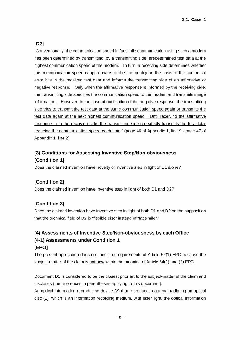
[D2] “Conventionally, the communication speed in facsimile communication using such a modem
has been determined by transmitting, by a transmitting side, predetermined test data at the
highest communication speed of the modem. In turn, a receiving side determines whether
the communication speed is appropriate for the line quality on the basis of the number of
error bits in the received test data and informs the transmitting side of an affirmative or
negative response. Only when the affirmative response is informed by the receiving side,
the transmitting side specifies the communication speed to the modem and transmits image
information. However, in the case of notification of the negative response, the transmitting
side tries to transmit the test data at the same communication speed again or transmits the
test data again at the next highest communication speed. Until receiving the affirmative
response from the receiving side, the transmitting side repeatedly transmits the test data,
reducing the communication speed each time.” (page 46 of Appendix 1, line 9 - page 47 of
Appendix 1, line 2)
(3) Conditions for Assessing Inventive Step/Non-obviousness [Condition 1] Does the claimed invention have novelty or inventive step in light of D1 alone?
[Condition 2] Does the claimed invention have inventive step in light of both D1 and D2?
[Condition 3] Does the claimed invention have inventive step in light of both D1 and D2 on the supposition
that the technical field of D2 is “flexible disc” instead of “facsimile”?
(4) Assessments of Inventive Step/Non-obviousness by each Office (4-1) Assessments under Condition 1 [EPO] The present application does not meet the requirements of Article 52(1) EPC because the
subject-matter of the claim is not new within the meaning of Article 54(1) and (2) EPC.
Document D1 is considered to be the closest prior art to the subject-matter of the claim and
discloses (the references in parentheses applying to this document):
An optical information reproducing device (2) that reproduces data by irradiating an optical
disc (1), which is an information recording medium, with laser light, the optical information
- 9 -

3.1. Case 1
reproducing device comprising:
rotating device (4) which rotates the optical disc, and detecting device (3) which detects a
data error, wherein, data is reproduced by rotating the optical disc by means of the said
rotating device at the maximum rotational speed in the beginning (see page 33, line
1-9);data is reproduced by reducing the rotational speed by means of the said rotating
device each time when the said detecting device detects a data error (in the case the
predetermined value of error corrections is 1 (one)) in reproducing data (see page 33, line
15 - page 34, line 2); data is reproduced by rotating the optical disc at the unchanged
rotational speed when the said detecting device doesn’t detect a data error (in the case the
predetermined value of error corrections is 1 (one)).
As the number of data error corrections can also be 1 (one), effectively meaning that after
one data error correction the setting of the rotational speed is reduced, the document D1 is a
novelty destroying document. i.e. one error correction is covered by "A predetermined value
of error corrections" to be set to zero.
Alternatively, the feature of selecting the predetermined value to be set to zero is merely one
of several straightforward possibilities which the skilled person would select, depending on
the circumstances, without exercising inventive skill, in order to solve the problem posed.
[JPO] The differences between the claimed invention and the invention described in D1 are as
follows:
With respect to the criterion for reducing the rotational speed of the rotating device upon the
occurrence of a data error, the claimed invention causes the rotational speed to be reduced
whenever a data error has been detected. On the other hand, the invention described in D1
causes the rotational speed to be reduced when the number of error corrections is larger
than a predetermined value and the optical disc is recorded at low-speed rotation; and
the claimed invention reproduces data by rotating the optical disc at the unchanged
rotational speed when no data error is detected by the detecting device. On the other hand,
the invention described in D1 reproduces data by rotating the optical disc at the unchanged
rotational speed when the number of error corrections is smaller than a predetermined
value.
However, the function of the claimed invention and that of the invention described in D1 are
very close with respect to reducing the rotational speed depending on data error. And
- 10 -

3.1. Case 1
considering that the original problem in the invention described in D1 is to allow higher data
transfer rates by performing the read at the higher rotational speed (See, page 31 of
Appendix 1, line 13-16), a person skilled in the art would have naturally arrived at the idea of
reducing the rotational speed gradually instead of reducing the rotational speed excessively
at once. Therefore, it is only an exercise of ordinary creativity of a person skilled in the art
to modify the function of the invention described in D1 to reduce the rotational speed
whenever a data error has been detected and to rotate the disc at unchanged rotational
speed when no data error is detected.
Consequently, a person skilled in the art could have easily arrived at the claimed invention
from the invention described in D1 and it involves no inventive step. (Art. 29(2))
<< Reference >>
Examination Guidelines for Patent and Utility Model 1 in Japan states as follows:
“Whether or not a claimed invention involves an inventive step is determined whether the
reasoning that a person skilled in the art could have easily arrived at a claimed invention
based on cited inventions can be made by constantly considering what a person skilled in
the art would do after precisely comprehending the state of the art in the field to which the
present invention pertains at the time of the filing.
Concretely, after finding of a claimed invention and one or more cited inventions, one cited
invention most suitable for the reasoning is selected. And comparison of the claimed
invention with a cited invention is made, and the identicalness and the difference in matters
defining the inventions are clarified. Then, the reasoning for lacking an inventive step of the
claimed invention is attempted on the basis of the contents of the selected invention, other
cited inventions (including well-known or commonly used art) and the common general
knowledge. The reasoning can be made from various and extensive aspects. For example,
the examiner evaluates whether a claimed invention falls under a selection of an optimal
material, a workshop modification of design, a mere juxtaposition of features on the basis of
cited inventions, or whether the contents of cited inventions disclose a cause or a motivation
for a person skilled in the art to arrive at the claimed invention. If advantageous effects of the
claimed invention over a cited invention can be clearly found in the description in the
specification, etc., it is taken into consideration as facts to support to affirmatively infer the
involvement of an inventive step.
When the reasoning can be made as a result of the above method, the claimed invention
1 http://www.jpo.go.jp/cgi/linke.cgi?url=/tetuzuki_e/t_tokkyo_e/1312-002_e.htm
- 11 -

3.1. Case 1
should be denied its inventive step. When the reasoning cannot be made, the claimed
invention should not be denied its involvement of an inventive step. ”;
(Examination Guidelines for Patent and Utility Model, Part II, Chapter 2 Novelty and
Inventive Step, 2.4(1)(2))
“Close similarity of function, work or operation
If a close similarity in function, work or operation exists between a claimed invention and a
cited invention or between cited inventions, there can be a well-founded reasoning that a
person skilled in the art would have been led to the claimed invention by applying and
combining the cited inventions.” (Id. 2.5 (2));
“Suggestions shown in the contents of cited inventions
Suggestions shown in the contents of cited inventions relevant to a claimed invention can be
a strong ground for the reasoning that a person skilled in the art would have been led to the
claimed invention.” (Id. 2.5 (2));
“Selection of an optimal material, workshop modification of design, etc.
Among exercises of ordinary creativity of a person skilled in the art are a selection of an
optimal material from publicly known materials which achieve a specific object, an
optimization of a numerical value range, a replacement with equivalents, and a workshop
modification of design in applying specific technology. When the difference of a claimed
invention in comparison falls only under these categories, it is usually considered that a
person skilled in the art could have easily arrived at it, unless otherwise there is another
ground for inferring inventive step.” (Id. 2.5 (1)) .
[USPTO] D1 discloses that (pages 31-32)2 high speed disc drives generally use a low speed to
read/reproduce a disc recorded at low speed because reading at high speed leads to
errors.3 The disclosure aims to allow higher data transfer rates by performing the read at
the higher rotational speed of the drive. The document further discloses that if the number
of errors (as determined by the number of error corrections) is small one can still work at the
2 Problems to be Solved by the Invention. “..Therefore, desirably, even an information recording/reproducing apparatus having a high-speed rotation mode with a high rotational speed controls the rotational speed of a drive motor so that a reproduction operation is performed on a medium recorded at low-speed rotation by reducing the rotational speed.” 3 The background description of the problem to be solved itself can be anticipatory of the claimed invention. However, the detail is not called out and thus we would have to rely on knowledge of the art.
- 12 -

3.1. Case 1
higher speed. [Sentence bridging pages 33-34.] Thus, the document proposes setting a
“predetermined” number of errors – i.e., a threshold – for moving into a lower speed read
mode. See for example, page 36 “the number of error corrections performed in such a
manner is used as a measure for the control of switching the rotational speed of the drive
motor” and
“If the number of error corrections is larger than a predetermined value, e.g., four words,
the drive controller 10 determines that the set magneto-optical disk 1 has been written in the
low-speed rotation mode, and performs the subsequent recording operation or reproduction
operation by switching to the rotational speed of the low-speed rotation mode. Accordingly,
when the number of error corrections is small, the operation is continued in the initial
high-speed rotation mode.” (page 37, line 10-16)
“.. Since there is no problem as long as the number of error corrections is smaller than a
predetermined value… the high-speed rotation can be continued”. (page 38, line 1-4)
The system as described, effectively improves on a system where the predetermined value
was zero – requiring dropping the speed to match the recording speed if any errors
occurred.
The claim under examination requires the speed to be unchanged when there are no data
errors detected and to be dropped each time a data error is detected.
D1 detects errors and records an error correction in the read sector. It sets a maximum
tolerance on the number of errors for which it will continue at the high speed reproduction.
When the number of errors exceeds the threshold (“predetermined value”) the speed of
rotation is reduced. Clearly, when there are no errors, the threshold is not exceeded, and
the reference system continues to operate at the higher speed.
The claimed invention amounts to setting the “predetermined” value at zero. That is, no
error tolerance at all. A single error results in a reduction of rotation speed. This is
encompassed in the disclosed invention of D1. That is, the claim is anticipated by D1.
Alternatively, since the threshold is taught (by D1) to be “small,” one could reasonably
understand that the threshold may be set to zero, for example, either when the data is
expected to be poor, or when running in a default mode where the reproduction and the
recording are at the same speed.
- 13 -

3.1. Case 1
Stated differently, the claim would have been obvious to one of ordinary skill in the art based
on D1 because it would have been an obvious implementation to allow for backwards
compatibility – that is, to allow the D1 system to run in the ordinary unenhanced mode if
desired.
(4-2) Assessments under Condition 2 [EPO] The problem to be solved by D2 is to reduce the amount of time needed for the highest
communication speed to fall back to an optimum communication speed. The optimum
communication speed is decided by means of two measurements: a line-quality
measurement and a noise level upon silence measurement. The signal to noise ratio (S/N)
of the line is computed and is used to select the optimum speed for communication from a
table. The system does not look nor investigates into an error signal. It performs a
measurement of the line and with the obtained values at hand determines the appropriate
communication speed. In case that D2 would be needed to raise a lack of inventive step, the
document would not be suitable.
The person skilled in the art would not consult the speed setting system for a facsimile
apparatus, when faced with the problem of achieving an improved recording/ reproducing
device that writes/reads data at optimal rotational speeds of optical disks.
D2 does neither teach nor suggest a method that modifies the communication speed as the
result of an error, but uses the teaching to "measure" the quality of a communication line
and adapt the communication speed from an available table that has appropriate
communication speeds programmed that belong to different line quality.
To summarize: The claim would be inventive if D2 would have been needed to show a lack
of inventive step.
[JPO] Although the invention D2 is related to a facsimile machine, D2 states that, in order to
transfer data at a high speed, the invention described in D2 transfers, at first, test data at the
fastest communication speed. Then, when an error has been detected in the received data,
an appropriate communication speed is established by reducing the communication speed
gradually so that the data can properly be transferred.
Since the inventions described in D1 and D2 mutually coincide with each other in
transferring data at a high speed, it is appropriate to regard the above inventions as
- 14 -

3.1. Case 1
belonging to the identical technical field of data transfer.
The inventions described in D1 and D2 are correlated with each other in terms of technical
field. Further, since the above inventions respectively deal with the same problem in order
to transfer data at a high speed, it is also appropriate to judge that there is a motivation to
apply the invention described in D2 to the invention described in D1.
Consequently, it is recognized that the technical matter related to the different points
comprising the following sequence of processes could easily be conceived by a person
skilled in the art, wherein the sequence of processes comprise the following steps: a step of
reducing the rotational speed of the rotating device gradually whenever an error has been
detected, and a step of rotating the optical disc at the unchanged rotational speed without
reducing the rotational speed when no error is detected so that the rotation of the optical
disc can be maintained at as high a speed as possible.
<< Reference >>
Examination Guidelines for Patent and Utility Model Part II, Chapter 2 Novelty and Inventive
Step, 2.5 (2) “Probable cause or motivation”
“Close relation of technical fields
An attempt to apply a technical means in a related technical field in order to solve a problem
is a mere exercise of ordinary creativity of a person skilled in the art. A replaceable or
add-able means in a related technical field, for example, can be a strong ground for the
reasoning that a person skilled in the art would have been led to a claimed invention.”
“Close similarity of a problem to be solved
A close similarity of a problem to be solved can be a strong ground for the reasoning that a
person skilled in the art would be led to a claimed invention by applying or combining cited
inventions.”
[USPTO] Assume, for the sake of argument, that one would not set the threshold (of the system of D1)
to allow changing speed for each error, because that is not in the spirit of the disclosure of
the D1, which teaches being able to tolerate SOME error at higher speed.
Then, we look at D2.
D2 is directed to a means for establishing the communication speed for a facsimile
transmission. The standard method of establishing the data rate was for one party to
transmit test data at a given rate (usually the maximum available) and then receive a
- 15 -

3.1. Case 1
response from the other party. If there were errors in the transmission, then the party
resends trial data at a lower rate until some effective rate can be agreed upon. D2 saves
the time of this negotiation by determining the optimum data rate based on a measurement
of the signal to noise ratio on the line in a single test transmission. (What this reference
teaches is using a “sensor” to determine whether the speed should be changed without
looking at error. However, the claim in this case is directed to detecting an error and then
changing speed. This reference would be relevant to claims that monitor defocus or
run-out, and then adjust the speed without actually reading data and checking for error. )
D2, although also concerned with high speed data transfer, does not supply the presumed
deficiency of D1. There is no indication that a single error would result in a downgrade of a
given data transfer rate. In fact, the method does not look at error rate, but rather at signal
to noise ratio to determine an optimum speed based on a lookup table.
Thus, with respect to “Condition 2,” if D2 was needed to show lack of inventive step, then it
would not be effective for that purpose.
The claim would not have been obvious to one of ordinary skill in the art based on D1 and
D2.
(4-3) Assessments under Condition 3 [EPO] Under the Condition 3, D2 also does neither teach nor suggest a method that modifies the
communication speed as the result of an error, but uses the teaching to "measure" the
quality of a communication line and adapt the communication speed from a available table
with appropriate communication speeds programmed that belong to different line quality.
To summarize: The claim would be inventive if D2 would have been needed to show a lack
of inventive step.
[JPO] Under “Condition 3,” in addition to the reason mentioned with regard to “Condition 2,” the
connection between the technical fields of D1 and D2 is closer. Thus, the JPO considers a
person skilled in the art could have easily arrived at the claimed invention in light of both D1
and D2 under “Condition 3,” too.
[USPTO]
- 16 -
3.1. Case 1
In response to “Condition 3,” changing the context of D2 from a facsimile to a disc drive
would not change the analysis, as the defect is in the teaching not the field of use.
The claim would not have been obvious to one of ordinary skill in the art based on D1 and
D2.
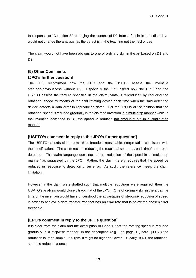
(5) Other Comments [JPO’s further question] The JPO reconfirmed how the EPO and the USPTO assess the inventive
step/non-obviousness without D2. Especially the JPO asked how the EPO and the
USPTO assess the feature specified in the claim, “data is reproduced by reducing the
rotational speed by means of the said rotating device each time when the said detecting
device detects a data error in reproducing data”. For the JPO is of the opinion that the
rotational speed is reduced gradually in the claimed invention in a multi-step manner while in
the invention described in D1 the speed is reduced not gradually but in a single-step
manner.
[USPTO’s comment in reply to the JPO’s further question] The USPTO accords claim terms their broadest reasonable interpretation consistent with
the specification. The claim recites “reducing the rotational speed . . . each time” an error is
detected. This claim language does not require reduction of the speed in a “multi-step
manner” as suggested by the JPO. Rather, the claim merely requires that the speed be
reduced in response to detection of an error. As such, the reference meets the claim
limitation.
However, if the claim were drafted such that multiple reductions were required, then the
USPTO’s analysis would closely track that of the JPO. One of ordinary skill in the art at the
time of the invention would have understood the advantages of stepwise reduction of speed
in order to achieve a data transfer rate that has an error rate that is below the chosen error
threshold.
[EPO’s comment in reply to the JPO’s question] It is clear from the claim and the description of Case 1, that the rotating speed is reduced
gradually in a stepwise manner. In the description (e.g. on page 11, para. [0017]) the
reduction is, for example, 600 rpm. It might be higher or lower. Clearly, in D1, the rotational
speed is reduced at once.
- 17 -

3.1. Case 1
As described for Condition 1, the number of data corrections can also be one, effectively
meaning that after one data error correction the setting of the rotational speed is reduced,
the document D1 is a novelty destroying document. I.e. one error correction is covered by "A
predetermined value of error corrections is one".
In light of D1 alone, Case 1 does not meet the requirements of Article 52(1)EPC because
the subject-matter of the claim is not new within the meaning of Article 54(1) and (2) EPC.
As a result of this lack of novelty the subject matter of the claim also lacks an inventive step
within the meaning of Article 56 EPC.
If on the other hand, as correctly stated by the USPTO, the claim would incorporate that the
reduction of rotational speed would be done by multiple reductions, then the subject matter
of this claim would lack inventive step within the meaning of Article 56 EPC.
The person skilled in the art, faced with the problem of recording/reproducing data at a
rotational speed that is as high as possible within a range of performance of a disc (see
description Case 1, par. [0001]) would use a step like reduction of rotational speed without
exercising inventive skill, in order to solve the problem posed.
(6) Brief Summary of Results EPO results JPO results USPTO results
Condition 1 (D1 alone)
Not Novel Not Inventive
Novel Not Inventive
Not Novel Not Inventive
Condition 2 and 3(combination of D1 and D2)
D2 not relevant for the problem to be
solved Not Inventive
D2 does not supply the
missing teaching The Trilateral Offices share the view that the claimed invention doesn’t include inventive
step in light of D1 alone (Condition 1).
However, the JPO’s result is different from that of the EPO and the USPTO. The JPO
considers the claimed invention to be novel compared with D1 because there is a difference
between the claimed invention and the invention described in D1 but it is not inventive in
light of D1 alone (Condition 1) or both D1 and D2 (Condition 2 and Condition 3).
- 18 -

3.1. Case 1
On the other hand, the EPO and the USPTO are of the opinion that there is no difference
between the claimed invention and the invention described in D1. Therefore they come to
the conclusion that the claimed invention is not novel and even if there is a slight difference
between the inventions, the claimed invention would have been easily arrived at from D1
(Condition 1). However, the EPO and the USPTO consider that D2 is not needed
because it is difficult to show a lack of inventive step of the claimed invention by applying the
feature described in D2 to the invention described in D1 (Condition 2 and Condition 3).
(7) Analysis for Case 1 With regard to Case 1, the result is different between the JPO and the other two Offices.
In this particular case, there are following differences.
A) Determination of the claimed scope
B) Determination of invention described in the prior art document
C) Combination of the prior art documents
(A) Determination of the claimed scope
Under Condition 1, the USPTO and the EPO consider the claimed invention to lack novelty.
However, the JPO considers novelty to exist. The difference derives from the difference in
the interpretation of the words in the claim.
The USPTO accords the claim terms their broadest reasonable interpretation consistent
with the specification. Specifically, the USPTO interprets the expression “reducing the
rotational speed . . . each time” in the claim to also mean the reduction of the rotational
speed only one time. The EPO determines the claimed scope in the same way as the
USPTO.
On the other hand, the JPO considers the wording to mean reducing the rotational speed
gradually in a multi-step manner because the original Japanese words translated into “each
time” generally means “every time of two or more times”.
(B) Determination of invention described in the prior art document
Under Condition 2 or 3, there is a difference in the determination of the invention in the prior
art D2.
The JPO extracts the invention described in D2 from the column of “Related Art” in D2
because the protocol described in the column of “Related Art” in D2 is similar to the method
of establishing an appropriate speed in the claimed invention.
On the other hand, the EPO and the USPTO determine the invention described in the prior
- 19 -

3.1. Case 1
art D2 from the entire prior art document D2 and not just limited to that which was described
in the column of “Related Art.”
(C) Combination of the prior art documents
Affected by the above difference in the determination of invention described in D2, a
difference arises in consideration of the combination of D1 and D2.
The JPO is of the opinion that a person skilled in the art could have applied the function
described in “Related Art” in D2 to the invention described in D1.
On the other hand, the USPTO and the EPO consider that it is difficult for a person skilled in
the art to combine D1 and the method described in the prior art document D2. USPTO
and EPO are of the opinion that the method of computing the S/N ratio and selecting the
optimum speed cannot be applied to the invention described in D1.
- 20 -

3.2. Case 2
3.2. Case 2 (1) Outline of the Application (See Appendix 2 in detail.) [Claim] A spring structure comprising circular rubber plates and metallic plates that are alternately
laminated, wherein the following conditions are met:
(1) t ≥ 5mm,
(2) D/t ≥ 50,
(3) 8>D/h>5, and
(4) the hardness of each rubber plate is less than 40,
Wherein the thickness of each rubber plate is defined as “t,” the diameter of each rubber
plate is defined as “D”, and the total thickness of the rubber plates is defined as “h.”
[Drawings]
[Description] “In light of the conventional technical problems, the claimed invention aims to provide
improved spring structures, which are capable of providing substantial deformation
capability “δ/h” and stable shear spring modulus KH that can remain invariable even when
the vertical load is actually variable.” (page 6 of Appendix 2, line 1-3)
“Based on the viewpoint of the restriction on the hardness and the form of the rubber plates
in the aforementioned spring structure, since the physical characteristics of the spring
structure can be determined by way of specific factors including hardness, elastic modulus,
the thickness of each rubber plate layer “t,” the ratio “D/t” (primary form ratio) between the
thickness “t” and the diameter “D” of each rubber plate, and the ratio “D/h” (secondary form
ratio) between the total thickness “h” and the diameter “D” of the rubber plates, after having
conducted various experiments on trial samples, the inventors eventually discovered the
- 21 -
3.2. Case 2
practical extent of the factors above to which the aforementioned object could be achieved.”
(page 6 of Appendix 2, line 14-21)
(2) Outline of the Prior Art
D1: Published prior art 1 in Appendix 2 [D1] “The Pad type aseismic isolators” named “A37 – 300 x 5 - 12” is described in Table 2-2.
“The Pad type aseismic isolators” means a spring structure comprising circular rubber plates
and metallic plates that are alternately laminated in this technical field.
That is to say, the spring structure comprising circular rubber plates and metallic plates that
are alternately laminated, wherein hardness of rubber plate is 37, diameter of rubber plate
“D” is 300mm, thickness of rubber plate “t” is 5mm, and the number of rubber plate layers is
12, is described in D1. The total thickness of the rubber plates “h” is 60mm (which means
thickness of rubber plate “t” (= 5mm) times number of rubber plate layers “12”).
Therefore, the spring structure described in D1 has the following characteristics,
(1) t = 5mm,
(2) D/t = 60,
(3) D/h = 5,
(4) the hardness of each rubber plate is 37.
It is also described as “any increase of the deformation amount was not substantially
confirmed in the sheared aseismic isolators having a minimum of 250mm in diameter when
the compressive load increased” in “(ii) Compressive shearing experiments” in “3. Results
and discussions”.
(3) Assessment of Inventive Step/Non-obviousness by each Office [EPO] The present application does not meet the requirements of Article 52(1) EPC because the
subject matter of the claim in Case 2 does not involve an inventive step within the meaning
of Article 56 EPC.
The subject matter of the claim differs from the known spring structure in that:
The condition of 8>D/h>5 is not met (D/h = 5.)
- 22 -
3.2. Case 2
The problem to be solved by the present invention may therefore be regarded as:
To provide an improved spring structure.
The solution proposed in the claim of Case 3 cannot be considered to involve an inventive
step (Articles 52(1) and 56 EPC), for the following reasons:
In order to be within the claimed range of 8>D/h>5, e.g. D/h = 6, means that with the same
total thickness " h " = 60 mm, " D " needs to be 360 mm. In fact a range of values for
diameter D bigger then 300 mm and under 479,4 mm with the same total thickness " h " = 60
mm will result in compliance with the condition (3) of the claim, 8>D/h>5. A similar range of
values can be found for "h" with "D" set to 300mm.
Taking into account the results of the study from D1 and the table 2-2 it is clear to see that
the properties of the aseismic isolator improve when the diameter " D " increases,
see e.g. the details in table 2-2 of "A 37 - 250 X 5 -12" and "A 37 - 300 X 5 - 12" .
It comes therefore within the scope of the person skilled in the art to further vary the
Diameter "D" in order to further improve the properties of the isolator. With trial and error he
will, without involving an inventive step come to an isolator that has a Diameter " D " that is
bigger then 300 mm and therefore to a D/h that meets the condition of 8>D/h>5. Hence, no
inventive step is present in the subject matter of the claim of Case 2 (Articles 52(1) and 56
EPC).
[JPO] Comparing the claimed invention and the invention described in D1, the difference is that
while the concerned invention meets the condition “8>D/h>5”, the “D/h” is 5 in the invention
described in D1.
D1 contains the following descriptions:
“Any increase of the deformation amount was not substantially confirmed in the sheared
aseismic isolators having a minimum of 250mm in diameter when the compressive load
increased” (“(ii) Compressive shearing experiments” on page 13 of Appendix 2); and,
“As a result of the conduction of the current serial experiments, it has become possible to
properly design a constantly stable horizontal spring that can ignore influence of variable
compressive force.” (“4. Conclusion” on page 15 of Appendix 2)
- 23 -
3.2. Case 2
It is thus recognizable that the invention described in D1 deals with the problem to be solved
same as the problem in the claimed invention, since the problem to be solved in the claimed
invention is “to minimize the influence of varied load on the shear spring modulus KH”
shown on page 5. D1 further describes that the above problem has substantially been
solved with the spring structures having a minimum of 250mm in diameter. Hence, it
should be comprehended that a person skilled in the art could easily realize that the more
the diameter of the spring structures is expanded, the easier the problem would be solved.
With respect to 50 % and 100% in deformation rate, comparing the results of the aseismic
isolators entitled “A37 – 300 x 5 - 12” and “A37 – 250 x 5 - 12” described in Table 2-2 of D1,
the following is apparent:
The isolator “A37 – 300 x 5 - 12” proved to be superior to the isolator “A37 – 250 x 5 - 12” in
terms of minimizing the influence of varied load on the shear spring modulus KH. Especially,
it is apparent that the isolator “A37 – 300 x 5 - 12” is superior to the isolator “A37 – 250 x 5 -
12” with respect to 50% in the deformation rate at least.
Further, except for the diameter, there is no difference between the above two aseismic
isolators. In this case, the diameter of the isolator “A37 – 300 x 5 - 12” is greater than that of
the isolator “A37 – 250 x 5 - 12”, and thus, it is probable that, in order to further reduce the
potential influence of varied load on the shear spring modulus KH, a person skilled in the art
could easily conceive to expand only the diameter of the aseismic isolator without varying
numerical values of other factors in the invention described in D1.
Concretely, expanding only the diameter of the aseismic isolator without varying the
numerical values of other factors corresponds to the expansion of the above referred “D/h.”
Moreover, it is hardly acceptable that the effect of the claimed invention is an advantageous
effect in comparison with the invention described in D1, taking into consideration a detailed
description of the claimed invention.
<< Reference >>
Examination Guidelines for Patent and Utility Model in Japan states as follows:
“Suggestions shown in the contents of cited inventions
Suggestions shown in the contents of cited inventions relevant to a claimed invention can be
- 24 -

3.2. Case 2
a strong ground for the reasoning that a person skilled in the art would have been led to the
claimed invention.” (Examination Guidelines Part II Chapter 2 “Novelty and Inventive Step”
2.5 (2));
“Selection of an optimal material, workshop modification of design, etc.
Among exercises of ordinary creativity of a person skilled in the art are a selection of an
optimal material from publicly known materials which achieve a specific object, an
optimization of a numerical value range, a replacement with equivalents, and a workshop
modification of design in applying specific technology. When the difference of a claimed
invention in comparison falls only under these categories, it is usually considered that a
person skilled in the art could have easily arrived at it, unless otherwise there is another
ground for inferring inventive step.” (Id. 2.5 (1)) .
[USPTO] The only difference between the claimed invention and D1 is that the claim recites
“8>D/h>5,” but D1 has a value of “D/h” exactly equal to 5.
D1 indicates that for diameters greater than 250mm the horizontal spring constant is
essentially unchanged by increasing the compression load. In fact, the 300 mm discs show
similar properties.
The claim would have been obvious to one of ordinary skill in the art in view of the D1
because the nature of D1 indicates that the exact values are not the key, but the interplay of
the parameters. One of ordinary skill would not limit themselves to the exact values in the
table. The purpose of the technical report was to show how to design isolators with a range
of desirable properties and as such one of ordinary skill in the art would use these guidelines
to craft an isolator of dimensions appropriate to the application. It can be seen from table 2
that the increase of diameter from 250 to 300 mm with all else being held equal results in
better (or approximately the same) stability of Kh. [That is at 50% deformation rate 1.2%
variability vs. 6% for a doubling of the compression pressure, and 3.2% vs. 2.3% at 100%
deformation rate]. Furthermore, one observes from Figure 4 that for a given shearing force,
the deformation, δ, is larger for the wider diameter (300mm) rubber plate isolator. Thus,
larger diameters would naturally be investigated and if D increases by even a small amount
then D/h would then be strictly greater than 5 without affecting the other claimed
parameters.
- 25 -

3.2. Case 2
(4) Brief Summary of Results
EPO result JPO result USPTO result
Not Inventive Not Inventive Not Inventive
[Comparison of Claimed Invention with Prior Art] The Trilateral Offices share the same view on the difference between the claimed invention
and the invention described in D1.
Each Office recognizes that the difference between the claimed invention and the invention
described in D1 is the value of D/h, which is exactly equal to 5 in the cited document while it
is 8>D/h>5 in the claimed invention. [Assessment of Inventive Step] The Trilateral Offices share the view that the claimed invention involves no inventive step in
light of the invention described in D1.
Each Office comes to the conclusion that it is within the scope of the person skilled in the art
to increase the diameter “D” of the cited invention to meet the condition “8>D/h>5” from the
description of D1.
- 26 -
3.3. Case 3
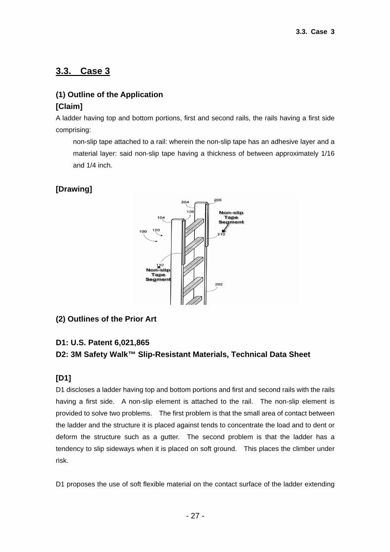
3.3. Case 3 (1) Outline of the Application [Claim] A ladder having top and bottom portions, first and second rails, the rails having a first side
comprising:
non-slip tape attached to a rail: wherein the non-slip tape has an adhesive layer and a
material layer: said non-slip tape having a thickness of between approximately 1/16
and 1/4 inch.
[Drawing]
(2) Outlines of the Prior Art D1: U.S. Patent 6,021,865 D2: 3M Safety Walk™ Slip-Resistant Materials, Technical Data Sheet [D1] D1 discloses a ladder having top and bottom portions and first and second rails with the rails
having a first side. A non-slip element is attached to the rail. The non-slip element is
provided to solve two problems. The first problem is that the small area of contact between
the ladder and the structure it is placed against tends to concentrate the load and to dent or
deform the structure such as a gutter. The second problem is that the ladder has a
tendency to slip sideways when it is placed on soft ground. This places the climber under
risk.
D1 proposes the use of soft flexible material on the contact surface of the ladder extending
- 27 -

3.3. Case 3
form 3 to 5 feet in length, with the soft flexible material having an exterior surface of a high
coefficient of friction. The contact surface can be attached to the ladder using internal
adhesive, double stick tape, or a hook and loop fastener.
D1 does not specifically disclose the thickness of the contact material.
[D2] D2 teaches slip resistant materials that come in pressure sensitive tape form and are
applied to structures where stable footing is desired. None of the 3M tape-like materials
are greater than 1/16 of an inch in thickness. The general purpose 600 material is
recommended for use on ladders, presumably on the tread or step.
D2 discloses thickness not greater than 1/16 of an inch.
(3) Assessment of Inventive Step/Non-obviousness by each Office [EPO] The present application does not meet the requirements of Article 52(1) EPC because the
subject matter of the claim does not involve an inventive step within the meaning of Article
56 EPC.
Document D1 is considered to be the closest prior art to the subject matter of the claim and
discloses (the references in parentheses applying to this document):
A ladder (50, 51) having top (top side of rails 132 and 133) and bottom (sides opposite top
side of rails (132, 133)) portions, first (132) and second (133) rails, the rails having a first
side (side facing the gutter 54), the ladder comprises a non-slip element (see figure 12,
reference 75) attached to a rail: wherein the non-slip element has an adhesive layer (71).
The subject matter of the claim therefore differs from this known ladder in that:
- 28 -

3.3. Case 3
• The non-slip element is non-slip tape.
• Said non-slip tape having a thickness of between approximately 1/16 and 1/4 inch.
The problem to be solved by the present invention may therefore be regarded as:
To provide a ladder with an increased stability.
The solution proposed in the claim of Case 3 cannot be considered to involve an inventive
step (Articles 52(1) and 56 EPC), for the following reasons:
D1 hints the person skilled in the art to the use of non-slip tape, by the wording of "a soft,
flexible material with a surface of high coefficient of friction" (column 9, line 23-30) and to "an
affixing means that can include an adhesive suitable, a conventional double-sided adhesive
strip" (column 11, line 35-40).
Therefore the feature of using non-slip tape instead of the non-slip element (75) is merely
one of several straightforward possibilities which the skilled person would select, depending
on the circumstances, without exercising inventive skill, in order to solve the problem posed,
especially when taking into account D2.
The feature that the non-slip tape has a thickness of between approximately 1/16 and 1/4
inch is merely one of several straightforward possibilities which the skilled person would
select, depending on the circumstances, without exercising inventive skill, in order to solve
the problem posed. I.e. the choice of the appropriate thickness of the non-slip tape is a
routine task of the skilled person.
Consequently, the subject matter of the claimed invention lacks an inventive step.
[JPO] Comparing the claimed invention with the invention described in D1, the non-slip element of
the claimed invention is a non-slip tape having a thickness of between approximately 1/16
and 1/4 inch, while the non-slip element of D1 is the soft flexible material having an exterior
surface of a high coefficient of friction attached to the ladder using internal adhesive, double
stick tape.
The soft flexible material having an exterior surface of a high coefficient of friction described
in D1 as well as pressure sensitive tape described in D2 is used for the common purpose of
- 29 -
3.3. Case 3
preventing slipping and the material has the common function, work or operation of
preventing slipping.
A close similarity of a problem to be solved and a close similarity in function, work or
operation can be a strong ground for the reasoning that a person skilled in the art would be
led to a claimed invention by applying or combining cited inventions. (Examination
Guidelines for Patent and Utility Model, Part II, Chapter 2 Novelty and Inventive Step, 2.5(2))
Optimizing by experiment a numerical range is normally considered an exercise of ordinary
creativity of a person skilled in the art, and hence such an inventive step is denied in general.
(Id. 2.5(3))
Therefore, a person skilled in the art could have easily arrived at the claimed invention
replacing the non-slip element in the ladder of D1 with the tape described in D2 and
optimizing the thickness of the tape. The claimed invention does not contain an inventive
step.
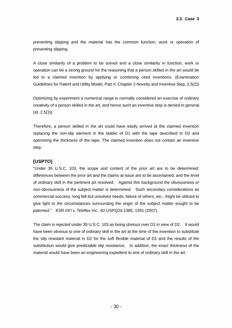
[USPTO] “Under 35 U.S.C. 103, the scope and content of the prior art are to be determined;
differences between the prior art and the claims at issue are to be ascertained; and the level
of ordinary skill in the pertinent art resolved. Against this background the obviousness or
non-obviousness of the subject matter is determined. Such secondary considerations as
commercial success, long felt but unsolved needs, failure of others, etc., might be utilized to
give light to the circumstances surrounding the origin of the subject matter sought to be
patented.” KSR Int’l v, Teleflex Inc., 82 USPQ2d 1385, 1391 (2007).
The claim is rejected under 35 U.S.C. 103 as being obvious over D1 in view of D2. It would
have been obvious to one of ordinary skill in the art at the time of the invention to substitute
the slip resistant material in D2 for the soft flexible material of D1 and the results of the
substitution would give predictable slip resistance. In addition, the exact thickness of the
material would have been an engineering expedient to one of ordinary skill in the art.
- 30 -

3.3. Case 3
(4) Brief Summary of Results
EPO result JPO result USPTO result
Not Inventive Not Inventive Not Inventive
[Comparison of Claimed Invention with Prior Art] The Trilateral Offices share the same view on the difference between the claimed invention
and the invention described in D1.
The EPO considers there are two differences and the JPO and the USPTO considers there
to be one difference but their opinions are substantially the same. Each Office considers
the claimed invention and the invention described in D1 to differ in that the non-slip element
in the invention in D1 is not a tape and the thickness of the non-slip element is not disclosed
in D1, while in the claimed invention, the non-slip element is non-slip tape having a
thickness of between approximately 1/16 and 1/4 inch.
[Assessment of Inventive Step] The Trilateral Offices share the view that the claimed invention involves no inventive step.
Each Office comes to the conclusion that a person skilled in the art would have substituted
the non-slip tape in D2 for the non-slip element of the invention described in D1 and that the
choice of the appropriate thickness of the non-slip tape is a routine work, an optimizing of a
numerical range or engineering expedient of a skilled person.
- 31 -
3.4. Case 4
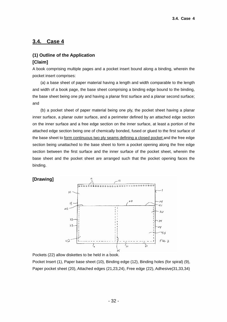
3.4. Case 4 (1) Outline of the Application [Claim] A book comprising multiple pages and a pocket insert bound along a binding, wherein the
pocket insert comprises:
(a) a base sheet of paper material having a length and width comparable to the length
and width of a book page, the base sheet comprising a binding edge bound to the binding,
the base sheet being one ply and having a planar first surface and a planar second surface;
and
(b) a pocket sheet of paper material being one ply, the pocket sheet having a planar
inner surface, a planar outer surface, and a perimeter defined by an attached edge section
on the inner surface and a free edge section on the inner surface, at least a portion of the
attached edge section being one of chemically bonded, fused or glued to the first surface of
the base sheet to form continuous two ply seams defining a closed pocket and the free edge
section being unattached to the base sheet to form a pocket opening along the free edge
section between the first surface and the inner surface of the pocket sheet, wherein the
base sheet and the pocket sheet are arranged such that the pocket opening faces the
binding.
[Drawing]
Pockets (22) allow diskettes to be held in a book.
Pocket Insert (1), Paper base sheet (10), Binding edge (12), Binding holes (for spiral) (9),
Paper pocket sheet (20), Attached edges (21,23,24), Free edge (22), Adhesive(31,33,34)
- 32 -

3.4. Case 4
(2) Outline of the Prior Art D1: U.S. Patent 5,540,513 D2: U.S. Patent 1,495,953 [D1] D1 discloses at least one pocket formed between a card and a tab yielding panel, wherein
the card may be of any convenient size or shape. The pocket (24) is described as facing
toward apertures (30) for a three ring binder. Any convenient bonding method including
adhesive can be used to secure tab yielding panel (11) to card (10). The tab yielding panel
(11) is folded inward to form the pocket. The tab yielding panel and the base sheet (22) is
made of one piece construction. D1 does not disclose a continuous “two ply seam defining
a pocket with a closed end”.
Paper base sheet (22)
Inwardly folded tab yielding panel (11)
Binding edge (14)
[D2] D2 discloses a two ply seam defining a pocket with a closed end (4, 1). The pocket may be
secured by any suitable means.
Fly leaf (1)
Pocket (4)
Joined edges (5)
- 33 -

3.4. Case 4
(3) Assessment of Inventive Step/Non-obviousness by each Office [EPO] The present application does not meet the requirements of Article 52(1) EPC because the
subject matter of the claim does not involve an inventive step within the meaning of Article
56 EPC.
The subject matter of the claim differs from the known book disclosed in D1 in that:
The closed pocket is formed by a continuous two ply seam.
The problem to be solved by the present invention may therefore be regarded as:
To provide an improved pocket insert for a bound book.
The solution proposed in the claim of Case 4 cannot be considered to involve an inventive
step (Articles 52(1) and 56 EPC), for the following reasons:
The main difference between the invention and the closest prior art D1 is the fact that in D1
the pocket is obtained by a fold line (on the side of the tabs 12) and by two inwardly folded
parts (28) and (26). In the claimed invention the pocket is formed by a two ply seam.
This slight constructional change in the way the pocket is formed comes within the scope of
the customary practice followed by persons skilled in the art, especially as the advantages
thus achieved can be readily contemplated in advance.
Moreover the use of a two ply seam in order to form a pocket is, in the same technical field,
also known from D2. (See page 1, line 54-60).
Consequently, the subject matter of the claimed invention lacks an inventive step.
[JPO] Comparing the claimed invention and the invention described in D1, the difference is that
while the continuous two ply seams define a closed pocket in the claimed invention, the
invention described in D1 (col.2, line 57-59) doesn’t have the continuous two ply. In other
words, in the invention described in D1, the top marginal panel 26 and the bottom marginal
panel 28 are folded inwardly and they overlap and are secured to the upper and lower
portions of the tab-yielding panel 11 respectively. Therefore, the secured portions make up
three ply. And on other points, both inventions are identical.
- 34 -

3.4. Case 4
The above difference is discussed below.
D2 discloses the loose leaf having a two ply seam defining a pocket with a closed end.
Since both inventions described in D1 and D2 belong to the same technical field of loose
leaf having a pocket, a person skilled in the art could have easily made the claimed
invention by applying the two ply seam defining a pocket with a closed end in the invention
described in D2 to the invention described in D1 for securing the tab yielding panel to the
card. (See Examination Guidelines for Patent and Utility Model, Part II, Chapter 2 Novelty
and Inventive Step, 2.5(2) “1) Close relation of technical fields”)
<< Reference >>
Examination Guidelines for Patent and Utility Model in Japan states as follows:
“Close relation of technical fields
An attempt to apply a technical means in a related technical field in order to solve a problem
is a mere exercise of ordinary creativity of a person skilled in the art. A replaceable or
add-able means in a related technical field, for example, can be a strong ground for the
reasoning that a person skilled in the art would have been led to a claimed invention.”
(Examination Guidelines Part II Chapter 2 “Novelty and Inventive Step” 2.5 (2)).
[USPTO] “The question of obviousness is resolved on the basis of underlying factual determinations
including (1) the scope and content of the prior art, (2) any differences between the claimed
subject matter and the prior art, (3) the level of skill in the art, and (4) where in evidence,
so-called secondary considerations.” See Graham v. John Deere and KSR Int’l Co. v.
Teleflex Inc.
The claim is rejected under 35 U.S.C. 103 as being obvious over D1 in view of D2. The
substitution of the continuous, two-ply seam of D2 for the folded seam of D1 is no more than
“the simple substitution of one known element for another or the mere application of a
known technique to a piece of prior art ready for improvement.” KSR, 82 USPQ2d at 1396.
Therefore, it would have been obvious at the time the invention was made to modify the
pocket insert in the invention described in D1 to attach a separate pocket sheet to a base
sheet to form a pocket insert with continuous two-ply seams as taught by D2.
- 35 -

3.4. Case 4
(4) Brief Summary of Results
EPO result JPO result USPTO result
Not Inventive Not Inventive Not Inventive
[Comparison of Claimed Invention with Prior Art] The Trilateral Offices share the view on the difference between the claimed invention and
the invention described in D1.
Each Office comes to the conclusion that the difference is that the pocket is obtained by a
fold line (on the side of the tab) and by two inwardly folded parts (top marginal panel 26 and
the bottom marginal panel 28) in the invention described in D1 while the closed pocket is
formed by a continuous two ply seam in the claimed invention.
[Assessment of Inventive Step] The Trilateral Offices share the view that the claimed invention involves no inventive step.
Each Office is of the opinion that a person skilled in the art would have modified the pocket
of the invention described in D1 to use the continuous two ply seam taught in D2.
- 36 -
3.5. Case 5
3.5. Case 5 (1) Outline of the Application Case 5 is based on a real case, (EP 0 332 231) with led to a decision in the Boards in
Appeal ( T1096/98). Both documents are available on the EPO Website.
[Claim] A device for milking animals, such as cows, comprising a milking parlour (1) with an entry
door (3), an exit door (4) and lateral guide means (27) giving the animal only a limited
freedom of movement and bounding the area of the milking parlour where the animal stands
during the milking process and with a manger (9) attached to the exit door (4) of the milking
parlour from which the animal can eat fodder during its stay in the milking parlour so that the
animal then is in a given position in the milking parlour, the device comprising a
computer-controlled milking machine with a milking cluster (34) couplable to the udder of the
animal and with a unit (28) suitable for either spraying a liquid or for spraying a liquid and
drying comprising a bowl-shaped basin (16) connectable to the udder of the animal and
provided with spraying means (32) for spraying said liquid against the animal's udder and
teats, said liquid being a cleaning, rinsing or disinfecting agent, the milking cluster (34) being
supported on a milking cluster support (17, 40, 41) and the unit (28) suitable for either
spraying a liquid or for spraying a liquid and drying being supported on a cleaning/drying unit
support (17, 40, 41), said milking cluster support (17, 40, 41) permitting an upwardly and
downwardly movement of the milking cluster (34), said cleaning/drying unit support (17, 40,
41) permitting an upwardly and downwardly movement of the unit (28) suitable for either
spraying a liquid or for spraying a liquid and drying, the milking cluster (34) being located in
its non-operative position on one side of said area and outside said area such that it is
adjacent to the udder of the animal when the animal is in the milking parlour, the milking
cluster support (17, 40, 41) and the cleaning/drying unit support (17, 40, 41) each
comprising a first vertical hinge pin (30) and being fastened to the floor of the milking parlour
in the region of the first hinge pin (30), each support (17) comprising a first connecting
member (40) swivelling around the first vertical hinge pin (30), a second vertical hinge pin
and a second connecting member (41) connected to the first connecting member (40) by the
second vertical hinge pin (31), the milking cluster (34) and the bowl-shaped basin of the unit
(28) suitable for either spraying a liquid or for spraying a liquid and drying being supported
on the respective second connecting member (41) of the support (17), the first vertical hinge
pin (30) permitting a swivelling movement of the support (17) and the second vertical hinge
pin (31) permitting a swivelling movement of the connecting members (40, 41) relative to
- 37 -

3.5. Case 5
each other so that the resulting movements of the milking cluster (34) and the unit (28)
suitable for either spraying a liquid or for spraying a liquid and drying are caused in such a
way that they approach the udder of the animal from the respective side of the milking
parlour between a foreleg and a hindleg of the animal and then move backwards to the
udder, the unit (28) suitable for either spraying a liquid or for spraying a liquid and drying
being couplable to the udder of the animal, the unit (28) suitable for either spraying a liquid
or for spraying a liquid and drying being located in its non-operative position on the other
side of said area and outside said area such that it is adjacent to the udder of the animal
when the animal is in the milking parlour.
[Drawings]
- 38 -

3.5. Case 5
(2) Outline of the Prior Art D2: EP 0 091 892 A2 D4: US 4,010,714 [D2] D2 discloses a milking device that has feeding and milking stalls arranged on a platform (Fig.
2, page 7, line 1-2). In each stall there is a manger with food dispensing means (page 7, line
3-4). Each stall is closable by means of gates or screens which are adapted to bring the cow
to take a defined position suitable for milking (page 7, line 10-13). There is a stationary robot
adapted to apply the milking means to the cow’s teats (page 7, line 21-23).
- 39 -

3.5. Case 5
[D4] D4 discloses the milking device comprising the washing unit (where drying is also done) with
a basin that moves upwardly and downwardly (column 3, line 55 – column 4 line 2).
(3) Assessment of Inventive Step/Non-obviousness by each Office [EPO] Starting from document D4, the problem to be solved is to provide a device for milking
animals, in which the cleaning unit and the milking cluster can be brought under the animal's
udder in a more efficient way. It has to be noted that the fact that the cleaning/drying unit and
the milking unit (ie the milking cluster) are located on different sides with respect to the
milking cluster - allows the milking unit to be brought into its operative position while the
cleaning/drying unit is brought into its non-operative position without risking that these units
- 40 -

3.5. Case 5
interfere with each other. This contributes substantially to improve the efficiency of the
milking device.
As far as the distinguishing unit (28) is concerned, if the skilled person starts from the
embodiment described in document D2 by referring to Figures 2 and 5 to 9, it would be
impossible for him to arrange the cleaning/drying unit on the side of the parlour opposite to
the side on which the milking unit is arranged because of the presence of entry and exit
doors on that side.
Moreover, it has to be noted that document D2 suggests to either arrange the cleaning unit
either "in each stall", ie inside the milking parlour, or attach it to the milking robot common to
all milking parlours or to arrange it on the support unit. Moreover, it could be possible to
arrange it on the same side as the milking unit. This means that the skilled person is not
obliged to arrange the cleaning unit as defined for unit (28) but has many other possibilities
(no one-way street situation).
The two lateral guide means are parts of the milking parlour which not only bound the central
area of the milking parlour (ie where the animal stands during the milking process) but also
define two lateral spaces where the milking unit and the cleaning unit, respectively, are
arranged and, thus, that these lateral areas are parts of the milking parlour. Therefore, even
if the skilled person - starting from the embodiment according to Figure 4 of document D2
were to arrange the cleaning unit opposite to the milking unit, these units would be arranged
outside the milking parlour.
There is no document in the prior art suggesting the arrangement of a manger on a door of a
milking parlour.
It can be derived from the Figure 2 of document D2 that the exit door (4'') is pivotally
connected to a link which is pivotally connected to the front side of the milking parlour. If the
skilled person were to start from this embodiment, it would be difficult for him to arrange the
manger on this lateral exit door, since the manger could interfere with the link during the
movement of the door. The description of the embodiment according to Figure 4 of
document D2 does not refer to any exit door but to "retaining means 4, preferably in the form
of a necklock" (page 9, lines 11 to 14), the manger being arranged on the front side of the
milking parlour, the rear side being open. Thus, it has to be understood that this embodiment
is not provided with a door. In any case, a door could only be arranged on the rear side of
- 41 -

3.5. Case 5
the milking parlour. Thus, if the skilled person were to start from this embodiment, it would
be impossible for him to arrange the manger on the rear door.
It has also to be noted that document D4 has to be understood as concerning a system for
managing cows in a stanchion stool in which the cow may stay for a longer time, ie not only
during the milking process, while the claimed milking device has to be construed as a device
for milking cows having a milking parlour which the cow enters in order to be milked and
leaves when the milking process has terminated. Therefore, there is no need in a system of
the type described in document D4 to arrange a separate exit door. Moreover, if an exit door
were to be arranged, it would not be expedient in such a system to arrange the manger on
the exit door of the stanchion stool instead of the manger or feeder 8.
The Board of Appeal came to the conclusion that it would not be obvious for a person skilled
in the art to arrive at a milking device in which the milking unit and the cleaning/drying unit
are located on the opposite sides of the milking parlour as defined in the claim on the basis
of the documents referred to by the parties.
[JPO] D2 discloses a milking device that has feeding and milking stalls arranged on a platform (Fig.
2, page 7, line 1-2). In each stall there is a manger with food dispensing means (page 7, line
3-4). Each stall is closable by means of gates or screens which are adapted to bring the cow
to take a defined position suitable for milking (page 7, line 10-13). There is a stationary robot
adapted to apply the milking means to the cow’s teats (page 7, line 21-23).
Comparing the claimed invention and the invention described in D2, the differences are in
that:
- D2 does not disclose that a manger is attached to the exit door
- D2 discloses the means for cleaning (page 8, line 5), but does not disclose that the
washing means has a bowl-shaped basin connectable to the udder of the cow or that has an
upward and downward movement
- D2 does not disclose placing the milking cluster on the other side of the washing means
D4 discloses the milking device comprising the washing unit (where drying is also done) with
a basin that moves upward and downward (column 3, line 55 – column 4 line 2).
However, D4 does not suggest placing the milking cluster on the other side of the washing
unit.
- 42 -

3.5. Case 5
Even if a person skilled in the art could have easily applied the washing unit disclosed in D4
to the milking device disclosed in D2, placing the milking cluster on the other side of the
washing unit is not a workshop modification of design or a mere juxtaposition of features.
For the reason above, the judgment of a lack of an inventive step of the claimed invention
cannot be made on the basis of the contents of the D2 and D4 and the common general
knowledge. The claimed invention should not be denied its inventive step.
[USPTO] Based on the disclosures of references D2 and D4, no reasoning or rationale has been
identified that would have prompted a person of ordinary skill in the art at the time of the
invention to modify the prior art automated milking systems to arrive at the claimed invention.
Although all of the elements of the claimed device are conventional in the art as evidenced
by the references, neither of the references teaches either (1) a milking unit situated on one
side of the animal and a cleaning/drying unit on the other, or (2) a manger attached to an exit
door.
Reference D2 provides a single robot to operate both the milking unit and the cleaning unit;
furthermore, the robot may be adapted to transport the units to multiple cows. It is not seen
that the milking unit and the cleaning unit of D2 could reasonably be positioned on opposite
sides of the cow while still retaining the advantages of a single robot to operate both units for
multiple cows. Reference D4 utilizes a recess beneath the cow to house the milking unit
and the cleaning unit when not in use, and the positioning of the teatcups is individualized
for each cow. Modifying reference D4 to use hinges to position the milking unit and the
cleaning unit on opposite sides of the cow would negate the feature of D4 that allows for
vertical and horizontal positioning of the teatcups as needed for each individual cow.
Neither reference D2 nor reference D4 teaches a manger attached to an exit door.
Reference D4 includes only a single behind the cow. The “gates or screens” of reference
D2 could be considered entrance and exits doors, but because they are situated at one side
of the cow, there would be no reason to position a manger on either of the gates.
For these reasons, the claimed invention would not have been obvious over prior art
references D2 and D4.
- 43 -

3.5. Case 5
(4) Brief Summary of Results
EPO result JPO result USPTO result
Inventive Inventive Inventive
[Assessment of Inventive Step] The Trilateral Offices share the view that the claimed invention should not be denied its
inventive step.
Each office is of the opinion that no reasoning or rationale has been identified that indicates
that a person of ordinary skill in the art would have arrived at the invention based on prior art
documents.
- 44 -
3.6. Case 6
3.6. Case 6 (1) Outline of the Application Case 6 is based on a real case, (EP 0 738 627) with led to a decision in the Boards in
Appeal ( T1153/04). Both documents are available on the EPO Website.
[Claim] An exterior mirror system for a vehicle comprising an exterior mirror assembly (26') including
a reflective element (28) contained within a housing (34') and a light source (126) also
contained within the housing (34') and adapted to project a light beam (66) downwardly and
rearwardly from the assembly (26') when mounted on the vehicle in order to provide a
lighted security zone adjacent the side of the vehicle to which the assembly is mounted, the
light source (126) being contained within an enclosure (116) within the housing (34'), the
enclosure (116) having a light-transmitting opening (122) and a cover (130) for the
light-transmitting opening (122), the light source (126) being positioned in the enclosure
(116) and radiating light through the light-transmitting opening (122), characterised in that
the reflective element (28) is adjustable within the housing (34'), and in that the light source
(126), enclosure (116) and cover (130) form a light module (104) removably positioned in
the housing (34') as a unit, the cover (130) being sealed to the enclosure (116) and the light
module (104) including a socket (124) for sealing the light source (126) in the enclosure
(116) such that the light module (104) is substantially moisture impervious in order to be
resistant to environmental elements.
[Description] “Personal security in and around vehicles has become an important concern. In particular,
an increasing number of assaults and robberies are committed in parking lots while
occupants are entering and exiting vehicles. ….. Accordingly, a need exists for a vehicle
security system to increase the security for vehicle occupants while entering and exiting the
vehicle.” (col. 1, lines 8-19)
“In this manner, the light source may be replaced by removing the light module from the
exterior mirror housing, removing the socket from the enclosure and replacing the light
source in the socket.” (col. 2, lines 9-13)
“An alternative vehicle personal security lighting system 25' includes a light module 104 that
is removably positioned within housing 34' of exterior mirror assembly 26' (Fig. 21).” (col. 8,
- 45 -
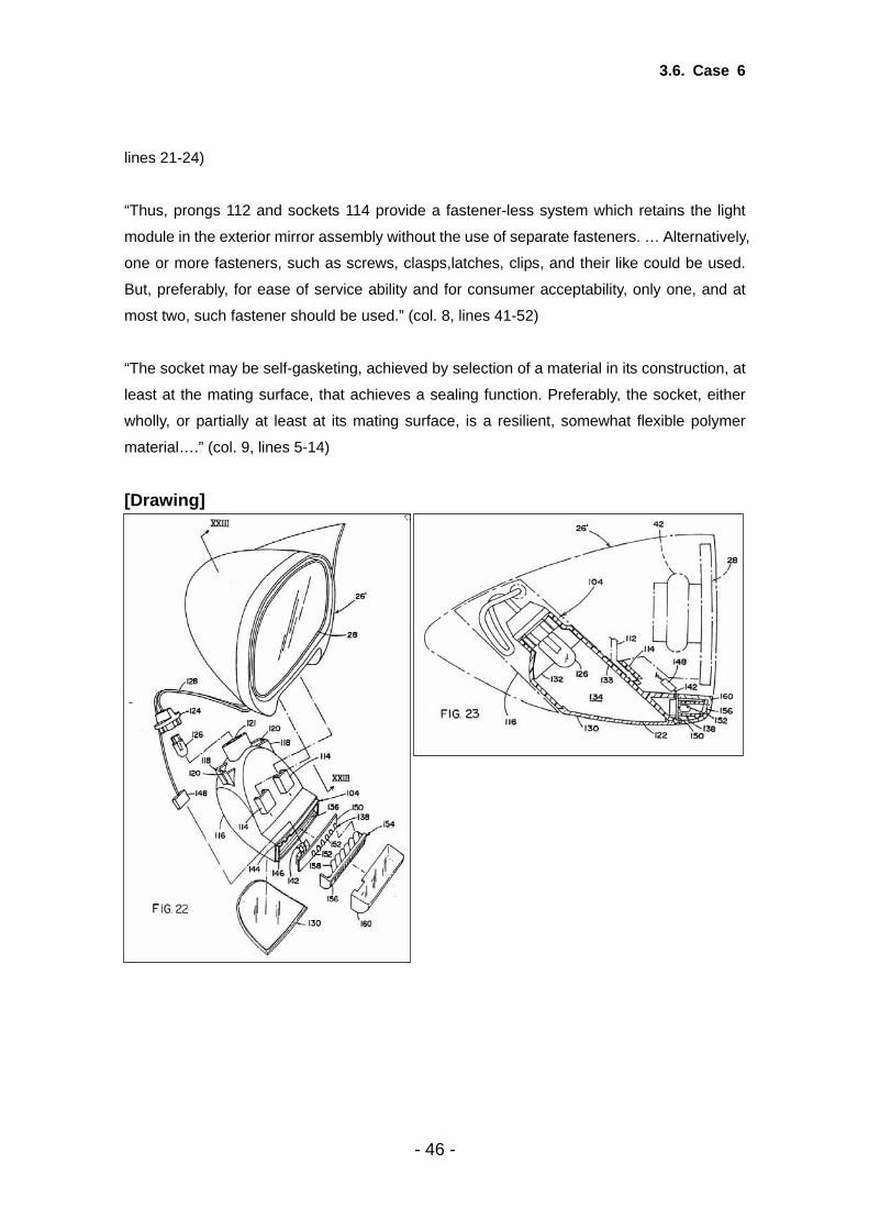
3.6. Case 6
lines 21-24)
“Thus, prongs 112 and sockets 114 provide a fastener-less system which retains the light
module in the exterior mirror assembly without the use of separate fasteners. … Alternatively,
one or more fasteners, such as screws, clasps,latches, clips, and their like could be used.
But, preferably, for ease of service ability and for consumer acceptability, only one, and at
most two, such fastener should be used.” (col. 8, lines 41-52)
“The socket may be self-gasketing, achieved by selection of a material in its construction, at
least at the mating surface, that achieves a sealing function. Preferably, the socket, either
wholly, or partially at least at its mating surface, is a resilient, somewhat flexible polymer
material….” (col. 9, lines 5-14)
[Drawing]
- 46 -

3.6. Case 6
(2) Outline of the Prior Art D1: GB-A-2275329 D3: JP-A-58188733 D20: EP-B-0525541 [D1] D1 discloses in its figure 8 and the corresponding parts of the description an exterior mirror
system comprising an exterior mirror assembly including a reflecting element contained
within a housing, the reflecting element being adjustable within the housing. It also discloses
a security light comprising a light source contained in the housing and adapted to project a
light beam downwardly and rearwardly from the assembly when mounted on the vehicle in
order to provide a lighted security zone adjacent the side of the vehicle.
- 47 -

3.6. Case 6
[D3] In the document D3 (See especially description from the 14th line of the column right below
in page 2 to the 4th line of the column upper left in page 3 and FIG.2-3) describes a turn
signal light mounted on the housing of an external mirror of a vehicle comprising the lens
removably positioned on the housing (4) by the bolt (12) and the light source (15) removably
plugged in the socket (14).
[D20] In the document D20 (English translation obtained by JPO) describes a vehicle light which
can be inserted into an opening in a vehicle body. The housing of the light is attached in the
opening of the vehicle body via a spring-loaded catch (5) which is located on one of its short
sides and is automatically released by exerting pressure or pulling. And the base (3) part is
welded or adhered to the lamp cover lens (2) (See line 14-17 in col. 4).
(3) Assessment of Inventive Step/Non-obviousness by each Office [EPO](detailed reasoning in the decision T1153 of the EPO Boards of Appeal) D1 does not disclose the following features of the subject-matter of the claim in issue:
(i) an enclosure containing the light source, within the housing, the enclosure having a light
- 48 -

3.6. Case 6
transmitting opening and a cover for the light transmitting opening, the light source being
positioned in the enclosure and radiating light through the light transmitting opening,
(ii) the light source, enclosure and cover forming a light module removably positioned in the
housing as a unit,
(iii) the cover being sealed to the enclosure,
(iv) the light module including a socket for sealing the light source in the enclosure such that
the light module is substantially moisture impervious in order to be resistant to
environmental elements.
The objective problem can thus be seen as increasing the ease of service, the reliability and
the durability of the security light according to D1. Increasing the ease of service, the
durability and the reliability of the different elements of a car is a constant desire of the
skilled person and thus an obvious problem to be solved.
In the opinion of the board the skilled person starting from the mirror system according to D1
and looking to solve the stated problem might in the light of D3 adopt the fixation of the lens
by screws which are easily removable when the light in the mirror has to be serviced and
provide a sealing or a round shaped buffering supporting member having elasticity similar to
rubber between the lens and the housing to dampen vibrations and improve durability.
However, even if he did so, this would not bring him to the subject-matter of the claim in
issue. A combination of D1 and D3 therefore does not destroy inventive step of the
subject-matter of the claim.
The board cannot agree with the argument that the statement in D20 that the lens is welded
or glued to the enclosure and the apparent illustration in figure 5 of an O-ring between the
socket and the enclosure means that the unit shown in figure 5 is sealed and that therefore
the skilled person would see the advantages of this construction and integrate it into the
mirror of D1. In the board's opinion this is a typical ex-post facto analysis of D20, since the
appellant having the knowledge of the invention sees advantages of the construction of D20
which are not described as such therein. Even if the sealing feature were implicitly disclosed
in D20, the skilled person would not be encouraged to adopt it since there is no mention
whatsoever of any advantage it brings. In order to come to the conclusion of the appellant
the skilled person would have to recognise these advantages.
The shape of the mirror housing of D1 and/or the shape of the unit shown in figure 5 of D20
would also have to be changed in order to adapt them for each other. In addition and
- 49 -

3.6. Case 6
contrary to the opinion of the appellant it seems improbable that the skilled person would
place the unit of D20 in the bottom of the housing of the mirror system of D1, since this
would involve moving away from the position of the security lamp on the rear face of the
mirror system which is known from the closest prior art D1 and which is less exposed to
environmental elements.
In summary the board considers that the skilled person would not look at D20 when seeking
a solution for an exterior mirror system with a lamp. Even if he nevertheless would do so, not
only would he have to recognise that the unit shown in figure 5 could be suitable to help him
but several steps would also be necessary to adapt it to the intended use in D1. The
combination of D1 with D20 therefore does not destroy inventive step of the present claim.
[JPO] Comparing the claimed invention and the invention described in D1, there are three
differences as follows and the inventions are identical on other points:
(i) While the light source (126), enclosure (116) and cover (130) form a removable light
module (104) positioned in the housing (34') as a unit in the invention described in the claim,
the casing (64) enclosing the light source (60) and the lens (64) isn’t removable in the
invention described in D1.
(ii) While the cover (130) is sealed to the enclosure (116) in the claimed invention, it is
ambiguous whether the lens (64) is sealed to the casing (34) in the invention described in
D1.
(iii) While the light module (104) includes a socket (124) for sealing the light source (126) in
the enclosure (116) such that the light module (104) is substantially moisture impervious in
order to be resistant to environmental elements in the invention described in the claim, it is
ambiguous whether the invention described in D1 has such a socket.
The above differences are discussed below.
(i) First, with regard to the difference (i) above, though D3 describes that the removable lens
(18) is positioned on the housing (4) by a bolt (12), it doesn’t describe a light module
removably positioned in the housing as a unit. Therefore, it was not obvious for a person
skilled in the art to arrive at the technical feature of the light module in the claimed invention
- 50 -

3.6. Case 6
from the technical features of D1 and D3.
On the other hand, D20 describes a vehicle light whose housing is removably attached in
the opening of the vehicle body via a spring-loaded catch. However, the invention
described in D20 relates to a general motor vehicle lamp or a license plate lamp for a vehicle
and there is no suggestion or implication in D20 for applying the technical feature of the
invention described in D20 to an exterior mirror system for a vehicle with a security light.
And any cause or motivation cannot be found for combining the general motor vehicle lamp
described in D20 and the light described in D1 which belongs to the specific technical field of
the exterior mirror system for a vehicle.
For the reason above, a person skilled in the art could not have easily made the technical
feature of the light module which is removable as a unit from the invention described in D1
and D20.
(ii) Second, with regard to the difference (ii) above, because sealing the external lens of a
vehicle light to the housing is a well-known art to the extent needless to cite reference, it is
within the range of design variation for a person skilled in the art to seal the lens (64) to the
casing (34) in the invention cited in D1.
(iii) Finally, with regard to the difference (iii) above, D3 describes a exterior mirror with a light
whose removable light source is (15) attached to a socket (14) (See description of the 7th
line of the column upper left in page 3 and FIG. 3) and in D20 the socket supporting the lamp
is shown in the drawing (See FIG 4).
However, D1, D3, D20 do not describe the light module as including a socket for sealing the
light source in the enclosure such that the light module is substantially moisture impervious
and resistant to environmental elements. Therefore, it was not obvious for a person skilled
in the art to fashion the technical feature of the socket in the claimed invention from those
prior art documents.
As explained above, the claimed invention involves an inventive step in the technical feature
in light of the differences (i) and (iii) above.
[USPTO] Based on the disclosures of references D1, D3, and D20, no reasoning or rationale has
been identified that would have prompted a person of ordinary skill in the art at the time of
- 51 -

3.6. Case 6
the invention to modify any of the prior art external vehicle light systems to arrive at the
claimed invention. Of the three prior art references, only reference D1 teaches an external
security light system for a vehicle that is mounted in the same housing as an external mirror.
Reference D3 does not teach a security light, and reference D20 does not teach a light
mounted in an external mirror housing. Furthermore, none of the references teaches
weather resistance. Thus, reference D1 is the closest prior art reference. The question is
whether, in view of references D3 and D20, it would have been obvious for a person of
ordinary skill in the art at the time of the invention to modify reference D1 to arrive at the
exterior mirror system for a vehicle comprising the removable, weather-resistant light
module of the claim. The references do not teach how to make a removable light module
as claimed, and it is not evident that a person of ordinary skill in the art at the time of the
invention could have done so, even if the desirability of such a modular system had been
recognized. As for sealing for the purpose of providing resistance to environmental factors,
the desirability of such protection would have been well-known to those of ordinary skill in
the art at the time of the invention, and could have been accomplished by way of rubber
gaskets or other means even absent an express teaching in these references. However,
this does not overcome the failure of the references to provide a means to fashion the
removable light module as claimed. Therefore, the claimed invention would not have been
obvious over the prior art references D1, D3, and D20.
(4) Brief Summary of Results
EPO result JPO result USPTO result
Inventive Inventive Inventive
[Assessment of Inventive Step] The Trilateral Offices share the view that the claimed invention should not be denied its
inventive step.
Each office is of the opinion that no reasoning or rationale is identified that indicates that a
person of ordinary skill in the art would have arrived at the invention based on prior art
documents.
- 52 -

4.1. Summary of Results
4. Summary of Results and Analysis 4.1. Summary of Results
Among the six cases, the Trilateral Offices have similar views of Case 2-6. However, with
regard to Case 1, the EPO and the USPTO consider that the claimed invention is not novel
and the JPO considers that the claimed invention is novel but not inventive. (see page
18-20)
The results of all cases are indicated in the following table.
EPO results JPO results USPTO results
Case 1 (D1 alone)
Not Novel Not Inventive
Novel Not Inventive
Not Novel Not Inventive
Case 1 (combination of D1 and D2)
D2 not relevant for the problem to be
solved Not Inventive
D2 does not supply the
missing teaching
Case 2 Not Inventive Not Inventive Not Inventive
Case 3 Not Inventive Not Inventive Not Inventive
Case 4 Not Inventive Not Inventive Not Inventive
Case 5 Inventive Inventive Inventive
Case 6 Inventive Inventive Inventive
- 53 -

4.2. Analysis
4.2. Analysis
Judging by the results of the case studies, the approaches of the Trilateral Offices to
examining inventive step are similar in that all three Offices define the difference between
the claimed invention and the prior art and consider whether a person skilled in the art would
have arrived at the claimed invention having regard to the state of the art.
If there is a reasonable basis for arriving at the claimed invention from the prior art, the
claimed invention doesn’t involve an inventive step. On the other hand, if there is no
reasonable basis for such a conclusion, the claimed invention involves an inventive step.
However, while the determination of inventive step is based on the “time the application was
filed (or the date of priority, if priority is claimed)” in the JPO and the EPO, where the
first-to-file principle has been adopted, it is based on the “time the invention was made” in
the USPTO, where the first-to-invent principle is adopted (see the explanation of the USPTO
in Case 1, 3-6).
The EPO applies the “Problem-and-solution approach”, consisting in identifying the
“objective technical problem” to be solved is identified after a determination of the closest
prior art (see the approach of the EPO in Case 2-6). On the other hand, it is not
necessary to define the objective problem to be solved in the JPO and the USPTO.
However, as is evident from the explanation of the reasoning in each case, the problem to
be solved by a person skilled in the art may be taken into account in the assessment of
inventive step in the JPO and the USPTO. In addition, under US law, in determining
obviousness/inventive step, neither the particular motivation to make the claimed invention
nor the problem the inventor is solving controls. The proper analysis is whether the
claimed invention would have been obvious to one of ordinary skill in the art after
consideration of all the facts.
- 54 -
5. Conclusion
5. Conclusion Of the six cases, the Trilateral Offices share similar views with regard to five cases.
However, in one case, the EPO and the USPTO consider that the claimed invention is not
novel and the JPO considers that the claimed invention is novel but not inventive. In that
particular case, there are differences in the determination of the scope of the claim and that
of the invention described in the prior art document, as well as in the way prior art
documents may be combined.
As a whole, the approaches of the Trilateral Offices to examining inventive step are similar in
that all three Offices define the difference between claimed invention and the prior art and
consider whether a person skilled in the art would have arrived at the claimed invention
having regard to the state of the art.
- 55 -

6. Appendix
6. Appendix Appendix 1: Case 1
Appendix 2: Case 2
- 56 -


