38
MICHAEL EMMENDORFER, SENIOR DIRECTOR OF SOLUTION ARCHITECTURE AND STRATEGY, OFFICE OF THE CTO COMPARING IEEE EPON & FSAN/ITUT GPON FAMILY OF TECHNOLOGIES
MICHAEL EMMENDORFER, SENIOR DIRECTOR OF SOLUTION ARCHITECTURE AND STRATEGY, OFFICE OF THE CTO
COMPARING IEEE EPON & FSAN/ITU-‐T GPON FAMILY OF TECHNOLOGIES
Copyright 2014 – ARRIS Enterprises, Inc. All rights Reserved.
2
TABLE OF CONTENTS OVERVIEW ...................................................................................................... 4 OVERVIEW OF PON TERMS AND TECHNOLOGIES .......................................... 5 FSAN/ITU-‐T GPON FAMILY .............................................................................. 6 ITU-‐T G.983 ..................................................................................................................... 6
ITU-‐T G.984 Series – GPON (Gigabit PON) ...................................................................... 7
ITU-‐T G.987 Series (XG-‐PON1 or XG-‐PON) ...................................................................... 7
ITU-‐T G.989 Series (NG-‐PON2 or TDWM-‐PON) ............................................................... 8
IEEE EPON FAMILY .......................................................................................... 8 IEEE 802.3ah – EPON or GEPON (Ethernet PON) ............................................................ 8
Turbo Mode EPON .......................................................................................................... 9
IEEE 802.3av 10G-‐EPON .................................................................................................. 9
SCTE IPS910 RFOG (RF OVER GLASS) ............................................................ 10 EXAMINING OPTICAL WAVELENGTH PLANNING AND CAPACITY ................. 11 Summary for Examining Optical Wavelength and Capacity ......................................... 12
EXAMINING PON BACKWARD COMPATIBILITY AND/OR COEXISTENCE ........ 13 Separate Fiber Coexistence .......................................................................................... 14
Wavelength Division Multiple Access (WDMA) Coexistence ........................................ 14
Time Division Multiple Access (TDMA) Coexistence: .................................................... 23
Time and Wavelength Division Multiplexing (TWDM): ................................................ 26
TELECOMMUNICATION EXAMPLES OF BACKWARDS COMPATIBILITY .......... 27 DOCSIS® ........................................................................................................................ 27
IEEE Wi-‐Fi (802.11) ........................................................................................................ 28
IEEE Ethernet 802.3 ...................................................................................................... 28
IEEE EPON and 10G EPON (802.3ah and 802.3av) ........................................................ 28
Fibre Channel ................................................................................................................ 28
G.fast ............................................................................................................................ 28
Summary of Backward Compatibility ........................................................................... 28
TYPES OF PON NETWORK ARCHITECTURES CENTRALIZED AND DISTRIBUTED (CAA & DAA) ................................................................................................. 29 9.1. Centralized Access Architecture (CAA) – PON: ................................................... 30
Copyright 2014 – ARRIS Enterprises, Inc. All rights Reserved.
3
Distributed Access Architecture (DAA) – PON .............................................................. 32
OPERATIONS ADMINISTRATION MAINTENANCE AND PROVISIONING (OAM&P) ...................................................................................................... 33 CONCLUSIONS .............................................................................................. 34 ACKNOWLEDGEMENTS ................................................................................ 35 REFERENCES ................................................................................................. 36 ABBREVIATIONS & ACRONYMS .................................................................... 37
Copyright 2014 – ARRIS Enterprises, Inc. All rights Reserved.
4
OVERVIEW
Cable operators around the world are examining the next generation of passive optical network (PON) technologies based on 10 Gbps technology and WDM (wavelength division multiplexing) using multiple wavelengths. To date, operators have used Active Ethernet and a variety of PON technologies for business services and some new build residential applications. There are two types of PON based networks, Ethernet PON (EPON) as defined by the IEEE and Gigabit PON (GPON) as defined by the ITU-‐T being the latest commercially deployed versions. The cable industry has added to these standards with Data Over Cable System Interface Specification (DOCSIS) Provisioning of EPON (DPoE) and a working group called DOCSIS Provisioning of GPON (DPG). The IEEE and ITU have defined 10 Gbps versions and are currently defining WDM standards capable of delivering 40 Gbps. So the question is which one of these technologies may be better suited for the cable industry? This paper focuses on several areas within the standards defined by the IEEE and the ITU-‐T that we believe are relevant in important decisions for cable service providers when considering the two types of PON based networks:
• Overview of PON Technologies • Backward Compatibility and/or Coexistence • Full Service Access Network (FSAN) / ITU-‐T GPON Family • IEEE EPON Family • PON Data Capacity • Types of PON Network Architectures Centralized and Distributed • MSO Back Office Compatibility to Support PON • PON Market and Economic Considerations
There are two key areas of assessment:
1. Which Data PON Technology Should an MSO Select (GPON Family or EPON Family)?
Choices: GPON Family: GPON and/or XG-‐PON1 and/or NG-‐PON2 vs. EPON Family: EPON and/or 10G-‐EPON
2. Which Type of PON Network Architecture Should an MSO Select?
Choices: Centralized Access Architecture (CAA) vs. Distributed Access Architecture (DAA)
Copyright 2014 – ARRIS Enterprises, Inc. All rights Reserved.
5
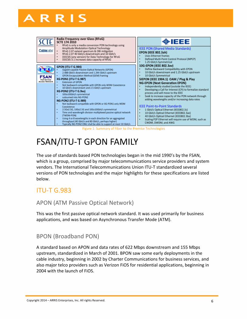
OVERVIEW OF PON TERMS AND TECHNOLOGIES The IEEE and SCTE have also defined PON standards for PON as well. Below are some of the terms and definitions used in this paper. ODN: Optical Distribution Network, referring to the outside plant (OSP). Items include fiber and splitters. The ODN is traditionally all passive, thus no powered equipment is in this network segment. Also called Outside Plant (OSP) OLT: Optical Line Terminal; located at the headend/central office (HE/CO). This network element controls the Downstream and Upstream transmission. The Downstream is broadcast to each premise, and the upstream transmission uses a multiple access protocol, called time division multiple access (TDMA). The OLT manages traffic to ensure bandwidth amount and priority for specified services. This is like a Cable Modem Termination System (CMTS) in the cable network. ONU: Optical Network Unit; located at the Customer Premise Equipment (CPE) (term associated with IEEE EPON). ONT: Optical Network Terminal; located at the CPE (term associated with FSAN / ITU-‐T version of PON) A summary of the previous and current releases of PON standards is captured in Figure 1, and additional description of these standards is listed below.
Copyright 2014 – ARRIS Enterprises, Inc. All rights Reserved.
6
Figure 1: Summary of Fiber to the Premise Technologies
FSAN/ITU-‐T GPON FAMILY The use of standards based PON technologies began in the mid 1990’s by the FSAN, which is a group, comprised by major telecommunications service providers and system vendors. The International Telecommunications Union ITU-‐T standardized several versions of PON technologies and the major highlights for these specifications are listed below.
ITU-‐T G.983
APON (ATM Passive Optical Network)
This was the first passive optical network standard. It was used primarily for business applications, and was based on Asynchronous Transfer Mode (ATM).
BPON (Broadband PON)
A standard based on APON and data rates of 622 Mbps downstream and 155 Mbps upstream, standardized in March of 2001. BPON saw some early deployments in the cable industry, beginning in 2002 by Charter Communications for business services, and also major telco providers such as Verizon FiOS for residential applications, beginning in 2004 with the launch of FiOS.
Copyright 2014 – ARRIS Enterprises, Inc. All rights Reserved.
7
ITU-‐T G.984 Series – GPON (Gigabit PON) This is an evolution of the BPON standard. It supports higher rates, enhanced security, and choice of data encapsulation mode, either ATM or GPON Encapsulation Method (GEM), although nearly all systems utilized GEM. This had an excellent line encoding method called non-‐return-‐to-‐zero (NRZ), well defined optical standards, and support for data services and TDM service via Circuit Emulation Service over Packet (CESoP) and Native TDM. Some key features are listed below:
• 2.488 Gbps Downstream x 1.244 Gbps Upstream • Additional PON management overhead varies and needs to be considered • 2.488G DS Wavelength at 1490nm ±10 (1480nm to 1500nm) • 1.244G US Wavelength at 1310nm ±50 (1260nm to 1360nm) known as
Wideband G.984.2 (year 2004) • 1.244G US Wavelength at 1310nm ±40 (1270nm to 1350nm) known as Reduced
(DFB) G.984.5 (year 2007) • 1.244G US Wavelength at 1310nm ±20 (1290nm to 1330nm) known as
Narrowband G.984.5 • Since 984.5 was released narrowband optics have been used to accommodate
future upstream wavelengths
ITU-‐T G.987 Series (XG-‐PON1 or XG-‐PON) A 10 Gigabit version was released in October of 2010 and these standards use the same wavelengths as those defined for 10G-‐EPON a year earlier. Some key features are listed below:
• Not backward compatible with GPON, only WDM Coexistence • 9.953 Gbps Downstream x 2.488 Gbps Upstream • 9.953 Gbps before encoding and forward error correction (FEC) 8.669 Gbps • 2.488 Gbps before encoding and FEC 2.290 Gbps • Additional PON management overhead varies and needs to be considered • 9.953 Gbps DS Wavelength DS at 1577nm ±2.5 (1475nm to 1480nm) • 2.488 Gbps US Wavelength US at 1270nm ±10 (1260nm to 1280nm) • Single Lambda downstream and upstream thus no Dual Rate Support
Copyright 2014 – ARRIS Enterprises, Inc. All rights Reserved.
8
ITU-‐T G.989 Series (NG-‐PON2 or TDWM-‐PON) The G.989 series is the latest standard underway and supports 10 Gigabit symmetrical and other speed tier options as well as support for multiple wavelengths across the PON. Some key features are listed below:
• Not backward compatible with GPON or XG-‐PON1, only WDM Coexistence • a.k.a. Time and wavelength division multiplexed passive optical network (TWDM-‐
PON) • 2.488 Gbps Downstream x 2.488 Gbps Upstream • 9.953 Gbps Downstream x 2.488 Gbps Upstream • 9.953 Gbps Downstream x 9.953 Gbps Upstream • 9.953 Gbps before encoding and FEC 8.669 Gbps • 2.488 Gbps before encoding and FEC 2.290 Gbps • Additional PON management overhead varies and needs to be considered • Supports 4 to 8 Lambdas: Downstream 1596-‐1603nm / Upstream 1524-‐1544nm • Using 4 or 8 wavelengths in each direction for an aggregated throughput (40
Gbit/s and 80 Gbit/s, perhaps higher) • Typically an NG-‐PON2 ONU shall be able to support at most 10 Gbit/s • Using 4 or 8 wavelengths in each direction independently as separate PON
systems on the same fiber or ODN, used to reduce service group size per PON MAC domain
IEEE EPON FAMILY The Institute of Electrical and Electronics Engineers (IEEE) 802 group defines a family of IEEE standards dealing with local area networks and metropolitan area networks. This standards body defined the Ethernet Protocol that is used in networking throughout the world. The IEEE and specifically the 802-‐working group defined several point-‐to-‐multipoint (P2MP) passive optical network (PON) standards referred to as 802.3ah and 802.3av.
IEEE 802.3ah – EPON or GEPON (Ethernet PON) EPON is an IEEE/ Ethernet in the First Mile (EFM) standard for using Ethernet for packet data. 802.3ah is now part of the IEEE 802.3 standard. The IEEE standardized 1G-‐EPON in 2004. Key features include:
• 1.25 Gbps Downstream x 1.25 Gbps Upstream • 1.25 Gbps after 8B/10B Encoding and no FEC is used yields 1 Gbps • Additional PON management overhead varies and needs to be considered
Copyright 2014 – ARRIS Enterprises, Inc. All rights Reserved.
9
• 1.25G DS Wavelength: 1490nm ±10 (1480nm to 1500nm) • 1.25G US Wavelength: 1310nm ±50 (1260nm to 1360nm) known as Wideband
G.984.2 • 1.25G US Wavelength: 1310nm ±20 (1290nm to 1330nm) known as Narrowband
as defined by ITU-‐T G.984.5 • Narrowband is not defined in the IEEE but is used worldwide and uses the same
optics as GPON
Turbo Mode EPON The term “Turbo Mode” EPON was a term coined by an EPON chipset supplier called Teknovus, which was later acquired by Broadcom. Turbo Mode EPON took the existing 1.25 Gbps downstream and overclocked the rate to deliver a data rate of 2.5 Gbps with a 2.0 Gbps payload, while the upstream was unchanged. This was an effort to compete with GPON, which has a 2.488 Gbps data rate. When operating in turbo mode EPON and using the standard EPON 1490 nm wavelength, the OLT overclocked 2.5 Gbps link allows only 2.5 Gbps ONUs to be supported on the PON. The use of 1G EPON ONUs and Turbo Mode 2G EPON ONUs on the same 1490 nm PON is not permitted. Recently, there is interest from the Cable industry to standardize Turbo Mode EPON through CableLabs. Key features include:
• 2.5 Gbps Downstream x 1.25 Gbps Upstream • 1G ONUs are not supported on the PON while the OLT is operating in Turbo
Mode • Additional PON management overhead varies and needs to be considered • Turbo mode developed by Teknovus (later acquired by Broadcom) • Not an IEEE Standard • Proposed to CableLabs for standardization
IEEE 802.3av 10G-‐EPON 10G-‐EPON (10 Gigabit Ethernet PON) is a standard that also supports the previous standard called 802.3ah EPON, thus is backward compatible. 10G-‐EPON may use separate wavelengths for 10G and 1G downstream, called Dual Rate Mode, if desired by the service provider. The upstream defines support for Time Division Multiplexing (TDM), which allows a single wideband receiver (1260 nm -‐1360 nm) in the OLT to receive both 10G and 1G upstream wavelengths. The 10G-‐EPON system will support two MAC domains and a single return path DBA that will support the TDM mode, allowing 10G and 1G bursts at different periods of time. The EPON ecosystem also enables the support for WDM coexistence like GPON and XG-‐PON, whereby EPON and 10G-‐EPON
Copyright 2014 – ARRIS Enterprises, Inc. All rights Reserved.
10
wavelengths in both directions may exist on the same PON. The IEEE standardized 10G-‐EPON in 2009. Key features are below:
• 1 Gbps Downstream x 1 Gbps Upstream (likely 2 G Down x 1 G up) • 10 Gbps Downstream x 1 Gbps Upstream • 10 Gbps Downstream x 10 Gbps Upstream • 10.3125 Gbps before encoding and forward error correction (FEC) 8.710 Gbps • Additional PON management overhead varies and needs to be considered • 10G DS Wavelength at 1577.5nm ±2.5 (1575nm to 1580nm) • 10G US Wavelength at 1270nm ±10 (1260nm to 1280nm) • 1G Down and Up, same options as above
SCTE IPS910 RFOG (RF OVER GLASS) RFoG (RF over Glass) is an SCTE Interface Practices Subcommittee standard in development for Point-‐to-‐Multipoint (P2MP) operations that may have a wavelength plan compatible with data PON solutions such as EPON or 10G-‐EPON. RFoG offers FTTH PON-‐like architecture for MSOs without having to select or deploy a PON technology. RF-‐over-‐Glass (RFoG) delivers triple play CATV services through a FTTH style network infrastructure (i.e. Fiber-‐to-‐the-‐Home). Essentially RFoG is a layer 1 media conversion approach for fiber to the premise that uses Hybrid Fiber Coax (HFC) technologies and extends the fiber to the home when a mini node called an RFoG ONU is placed at the home and performs media conversion from optical to coax. In RFoG, the coax portion of the network is just at the customer premise, allowing traditional cable installation practices to be leveraged. The use of traditional CATV headend equipment for video and data (DOCSIS) network uses RF headend signal processing connected to separate headend RFoG optical transport device. The RFoG transmitter and receivers do not have a MAC or PHY layer scheduler as found in typical PON technology, therefore this is not a Data PON technology. To enable coexistence with traditional Data PON systems, RFoG uses a 1551 nm forward (downstream) optical transmitter and a 1610 nm receiver (upstream) at the headend systems. The RFoG ONU providers the optical termination at the subscriber home and allowing traditional CATV CPE device such as set-‐top boxes (STB), DOCSIS modems, and VoIP E-‐MTAs to be used at the subscriber premise. RFoG allows MSOs to offer FTTP, while leveraging the entire existing back office systems – billing, provisioning and network management. There are new RFoG (optical beat interference) OBI Free Systems which features include:
• RFoG with OBI Free Splitter Combiner • High Capacity are possible that may exceed the capacity of 10G PON systems
Copyright 2014 – ARRIS Enterprises, Inc. All rights Reserved.
11
• Support for All Legacy Services • DOCSIS 3.x over RFoG • 1551 ± 6.5 nm optical downstream wavelength • 1 GHz RF bandwidth, 17dBmV RF Output level, 3dB operational tilt • 1610nm CWDM (Coarse Wave Division Multiplexed) Optical Upstream • 42/54 MHz RF Frequency Split, and other splits are possible
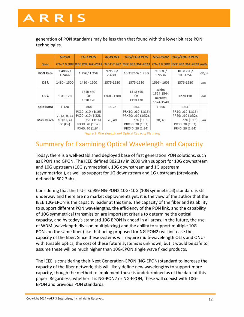
EXAMINING OPTICAL WAVELENGTH PLANNING AND CAPACITY The importance of wavelength planning is critical for service providers to maximize their fiber investment. Figure 2, below, captures the wavelengths defined by several standards organizations as well as those available in the market place. The IEEE defined upstream wavelength for 1G-‐EPON is 1310 nm +/-‐50 nm, allowing an optical range of 1260 nm to 1360 nm, a 100 nm wide range. The 1G-‐EPON 1310 nm +/-‐ 20 nm wavelength listed in the table for both 1G-‐EPON and 10G/1G-‐EPON is known as narrowband, which is not defined in the IEEE specification. In 2004 the GPON and EPON standards used the same upstream optical wavelength, 1260 to 1360 nm. However, in 2007 the ITU-‐T defined the GPON 984.5 specification defining 1310 nm +/-‐ 20 nm to accommodate for future wavelengths. The 1G-‐EPON upstream systems may use the “GPON 984.5” optical specification to accommodate for additional wavelengths as well, for example to support 1G-‐EPON and 10G-‐EPON upstream on the same fiber, but operated as separate PON networks. The IEEE and ITU-‐T also define targeted split ratios, but these targets may exceed those defined in the specifications. A higher split ratio is desirable to maximize the OLT PON port. This distributes the costs of an OLT across a wider customer base yielding better economics, but at the expense of less overall bandwidth available per customer. Often the market place supports higher split ratios than those defined. The PON rate in Figure 2, defines the payload data rate prior to encoding overhead, forward error correction (if used or required) and prior to additional PON management overhead. The actual throughput rate is also a major factor when considering PON alternatives. To measure the actual throughput there are many variables that need to be considered from packet size, number of ONUs, grant cycle time, guard band overhead, discover overhead and other overhead. There have been numerous papers and studies done over the years measuring the capacity of various PON technologies. The increase in packet size in the downstream and upstream direction, better encoding methods used for 10G-‐EPON, and the same FEC being used for 10G-‐EPON and XG-‐PON1 will likely diminish any perceived throughput difference between the standards. The efficiency of a given PON technology is important, but the difference in the 10G
Copyright 2014 – ARRIS Enterprises, Inc. All rights Reserved.
12
generation of PON standards may be less than that found with the lower bit rate PON technologies.
Figure 2: Wavelength and Optical Capacity Planning
Summary for Examining Optical Wavelength and Capacity Today, there is a well-‐established deployed base of first generation PON solutions, such as EPON and GPON. The IEEE defined 802.3av in 2009 with support for 10G downstream and 10G upstream (10G symmetrical), 10G downstream and 1G upstream (asymmetrical), as well as support for 1G downstream and 1G upstream (previously defined in 802.3ah). Considering that the ITU-‐T G.989 NG-‐PON2 10Gx10G (10G symmetrical) standard is still underway and there are no market deployments yet, it is the view of the author that the IEEE 10G-‐EPON is the capacity leader at this time. The capacity of the fiber and its ability to support different PON wavelengths, the efficiency of the PON link, and the capability of 10G symmetrical transmission are important criteria to determine the optical capacity, and by today’s standard 10G EPON is ahead in all areas. In the future, the use of WDM (wavelength division multiplexing) and the ability to support multiple 10G PONs on the same fiber (like that being proposed for NG-‐PON2) will increase the capacity of the fiber. Since these systems will require multi-‐wavelength OLTs and ONUs with tunable optics, the cost of these future systems is unknown, but it would be safe to assume these will be much higher than 10G-‐EPON single wave fixed products. The IEEE is considering their Next Generation-‐EPON (NG-‐EPON) standard to increase the capacity of the fiber network; this will likely define new wavelengths to support more capacity, though the method to implement these is undetermined as of the date of this paper. Regardless, whether it is NG-‐PON2 or NG-‐EPON, these will coexist with 10G-‐EPON and previous PON standards.
Copyright 2014 – ARRIS Enterprises, Inc. All rights Reserved.
13
In summary, the capacity of 10G-‐EPON is already 10Gx10G symmetrical and has been since 2009. Additionally, 10G-‐EPON supports multi-‐rate devices (10Gx1G and 1Gx1G) to accommodate legacy devices and/or allow lower price point ONUs to be used. A single 10G-‐EPON OLT port, using a method called TDMA, examined in detail in the following section, enables support for multiple IEEE ONU options.
EXAMINING PON BACKWARD COMPATIBILITY AND/OR COEXISTENCE This section examines methods selected by FSAN / ITU-‐T and the IEEE for supporting the coexistence of different PON types on the same fiber. These methods are vastly different and will likely be a major consideration area. Additional options that are available in the market place to enable coexistence and backward compatibility, if not explicitly defined in the standards will also be considered. These are three core methods of achieving coexistence:
1. Separate Fiber Coexistence o Separate fibers are required for each system if the PON systems have
overlapping wavelengths
2. Wavelength Division Multiple Access (WDMA) Coexistence o Coexistence of different ONU speed types using the wavelength domain o Each OLT port operates at its own native line rate (all ONUs on this port
are of the same data rate), but each OLT port is on a different wavelength o Also known as WDM (wavelength division multiplexing) Coexistence
(term used in FSAN/ITU-‐T for XG-‐PON1 and NG-‐PON2 standards) o Also known as Dual-‐rate WDM when used in EPON and 10G-‐EPON
3. Time Division Multiple Access (TDMA) Coexistence
o Coexistence of Different ONU Speed Types using Time Domain o An OLT port allocates different time-‐slots that may be for different data
rates depending on the device transmitting o PON link speed will vary depending on the device transmitting o Also known as Dual-‐rate TDMA “or” Dual-‐rate burst–mode reception o Also known as Backward Compatibility Mode
The following sections examine methods of attaining backward compatibility and coexistence with previous and future PON products in greater detail. Coexistence will
Copyright 2014 – ARRIS Enterprises, Inc. All rights Reserved.
14
likely be a major decision criterion for service providers selecting a new PON technology.
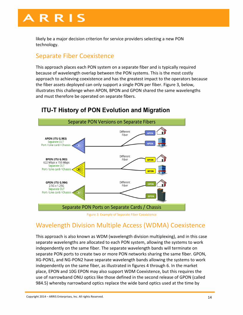
Separate Fiber Coexistence This approach places each PON system on a separate fiber and is typically required because of wavelength overlap between the PON systems. This is the most costly approach to achieving coexistence and has the greatest impact to the operators because the fiber assets deployed can only support a single PON per fiber. Figure 3, below, illustrates this challenge when APON, BPON and GPON shared the same wavelengths and must therefore be operated on separate fibers.
Figure 3: Example of Separate Fiber Coexistence
Wavelength Division Multiple Access (WDMA) Coexistence This approach is also known as WDM (wavelength division multiplexing), and in this case separate wavelengths are allocated to each PON system, allowing the systems to work independently on the same fiber. The separate wavelength bands will terminate on separate PON ports to create two or more PON networks sharing the same fiber. GPON, XG-‐PON1, and NG-‐PON2 have separate wavelength bands allowing the systems to work independently on the same fiber, as illustrated in figures 4 through 6. In the market place, EPON and 10G EPON may also support WDM Coexistence, but this requires the use of narrowband ONU optics like those defined in the second release of GPON (called 984.5) whereby narrowband optics replace the wide band optics used at the time by
Copyright 2014 – ARRIS Enterprises, Inc. All rights Reserved.
15
EPON and GPON. The use of blocking filters is also required at the ONU and OLT. WDMA can be summarized by the following attributes:
• Coexistence of Different ONU Speed Types using the Wavelength Domain • An OLT port operates at line rate because all ONUs are of the same data rate • Also known as WDM (wavelength division multiplexing) Coexistence term used
in FSAN/ITU-‐T for XG-‐PON1 and NG-‐PON2 standards • Also known as Dual-‐rate WDM used in EPON and 10G-‐EPON
WDM Coexistence using the GPON Family
The standards defined by FSAN and ITU-‐T only support WDM (wavelength division multiplexing) coexistence between GPON, XG-‐PON1 & NG-‐PON2 standards as shown in Figures 4-‐6, below. The use of WDM coexistence is possible because each standard defines separate wavelengths that do not overlap with the wavelengths used by other standards. Please note that for coexistence GPON must use the updated G.984.5 standards, which tightened the 1310 nm +/-‐50 nm wideband spectrum allocation to the narrowband 1310 nm +/-‐20 spectrum allocation in 2007. Some GPON deployments may still have wideband upstream in the installed base, and these GPON ONTs will have to be replaced to accommodate coexistence withXG-‐PON1 systems or even 10G-‐EPON systems that use the 1270 nm +/-‐10 nm upstream spectrum. Figure 4, illustrates that in order to support three different types of ONUs (2.5G x 1.2G, 10G x 2.5G, and 10Gx10G) the service provider would deploy three OLTs, each operating on a different standard, but operating over the same fiber using non-‐overlapping optical spectrums. Each network operates completely independently and at its standard line rate.

Copyright 2014 – ARRIS Enterprises, Inc. All rights Reserved.
16
Figure 4: FSAN / ITU-‐T WDM Coexistence Required for Single Fiber Deployments
Figure 5, illustrates an example of GPON and XG-‐PON1 coexistence with separate OLTs serving their corresponding ONUs.
Figure 5: XG-‐PON1 System (G.987 Series) Coexisting with G-‐PON [1]
Copyright 2014 – ARRIS Enterprises, Inc. All rights Reserved.
17
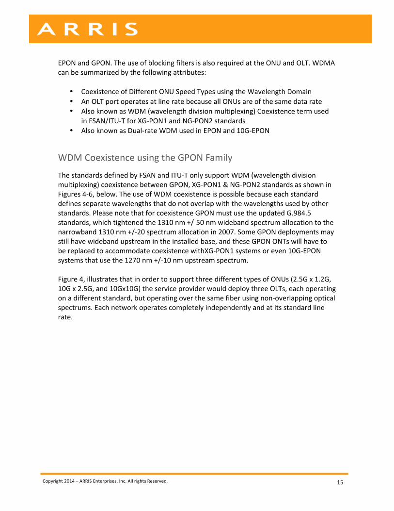
Figure 6: NG-‐PON2 System Coexistence with Legacy Systems [2]
Figure 6, taken from Recommendation ITU-‐T G.989.1, illustrates an example of GPON, XG-‐PON1, and NG-‐PON2 coexistence with three separate OLTs serving their corresponding ONUs. A key point of this paper is that GPON, XG-‐PON1 and NG-‐PON2 run parallel networks to service ONUs with different data rates and cost points. This requires three separate OLTs with three different ONU types. During the second half of this decade NG-‐PON2 products will enter the market, this standards defines support for multiple ONU speed types, 2G x 2G, 10G x 2G, and 10G x 10G it is uncertain at this time how many OLT ports either physical or logical will be needed to support these ONU combination types. Summary of WDM Coexistence using the GPON Family:
• Advantages: The WDM systems operate independently and the optical links are not shared with mixed (lower or higher) data rate devices, thus all ONUs operate at their native rate:
o Enables the service provider to use the same fiber at different data rates o Enables separate networks that operate independently on the same fiber o Lower speed ONUs do not impact the speed of other links o Enables each network to operate at its maximum capacity
• Disadvantages: WDM systems only allow a single data rate for a given OLT and
ONT, and supporting different data rates requires separate OLT/ONT systems. Separate systems will at a minimum require separate OLT ports, and very likely
Copyright 2014 – ARRIS Enterprises, Inc. All rights Reserved.
18
separate line cards or even chassis, and this will increase capital and operational costs for the operator:
o Requires “two or three” OLTs in the headend to support § GPON 2.5G x 1.2G (OLT Port / line card / chassis #1) § XG-‐PON1 10G x 2.5G (OLT Port / line card / chassis #2) § NG-‐PON2 10G x 10G (OLT Port / line card / chassis #3)
o Requires 2X or 3X OLT Ports / line cards / chassis o OLT resources increase facility space and power requirements o Cost is a major factor (3 OLTs to support 3 different ONT Types)
WDM and WDMA Coexistence using the EPON Family
The 10G-‐EPON standards define support for WDM (wavelength division multiplexing) coexistence on the downstream, which is referred to as downstream dual-‐rate WDM, allowing the OLT to transmit both 10 Gb/s and 1 Gb/s downstream signals [3]. The use of WDM or WDMA (Wavelength Division Multiple Access) is not clearly defined in the specifications for use in the upstream, because 802.3ah (1G-‐EPON) defined the upstream to have an optical range of 1310 nm +/-‐50 nm, meaning that 1G-‐EPON upstream occupies 1260 nm to 1360 nm, this known was wideband upstream. In the 10G-‐EPON standard, 802.3av, the upstream for 10 Gb/s is defined as 1270 nm +/-‐10nm, thus the 10G upstream channel occupies 1260 nm to 1280 nm and this means there is an overlap in the previously defined 1G-‐EPON standard. As stated in the PON overview sections, GPON initially defined 1260 nm to 1360 nm wideband upstream in 2004, the same as 1G EPON. Later, in 2007, the GPON committee went back and revised the upstream specification in G984.5 to 1310nm ±40nm (1270nm to 1350nm), which is known as reduced distributed feedback laser (DFB), and also to 1310nm ±20nm (1290nm to 1330nm), which is known as Narrowband. The IEEE never made such a formal adjustment to the optical layer of the specification. In the IEEE Standard 802.3av-‐2009, Annex 75A, page 83, it states, “If the OLT supports a single upstream data rate e.g., only 1 Gb/s or 10 Gb/s, the receiver can be designed to handle the designated upstream data rate and line code”. If the OLT designates a pair of receivers for upstream data rate of 1 Gb/s and 10 Gb/s upstream and the service provider desires to use the same fiber this can only be facilitated by using upstream optics that do not overlap. The 10G-‐EPON standard defines narrowband 1270 nm ±10 and if the 1G-‐EPON devices use 1310nm ±20 narrowband, then WDMA mode is possible for the EPON family as is the case for the revised GPON standard and XG-‐PON1. The use of 1G-‐EPON upstream with 1310nm ±20 narrowband is not only possible, but planned for use by cable operators so that EPON deployments will allow 10G-‐EPON upstream to be used on the same fiber and to have efficient use of the wavelengths. Because a service provider selects narrowband optics for use in their 1G-‐EPON upstream devices (1Gx1G, 2Gx1G, and 10Gx1G) some may consider this a violation of the IEEE standard.
Copyright 2014 – ARRIS Enterprises, Inc. All rights Reserved.
19
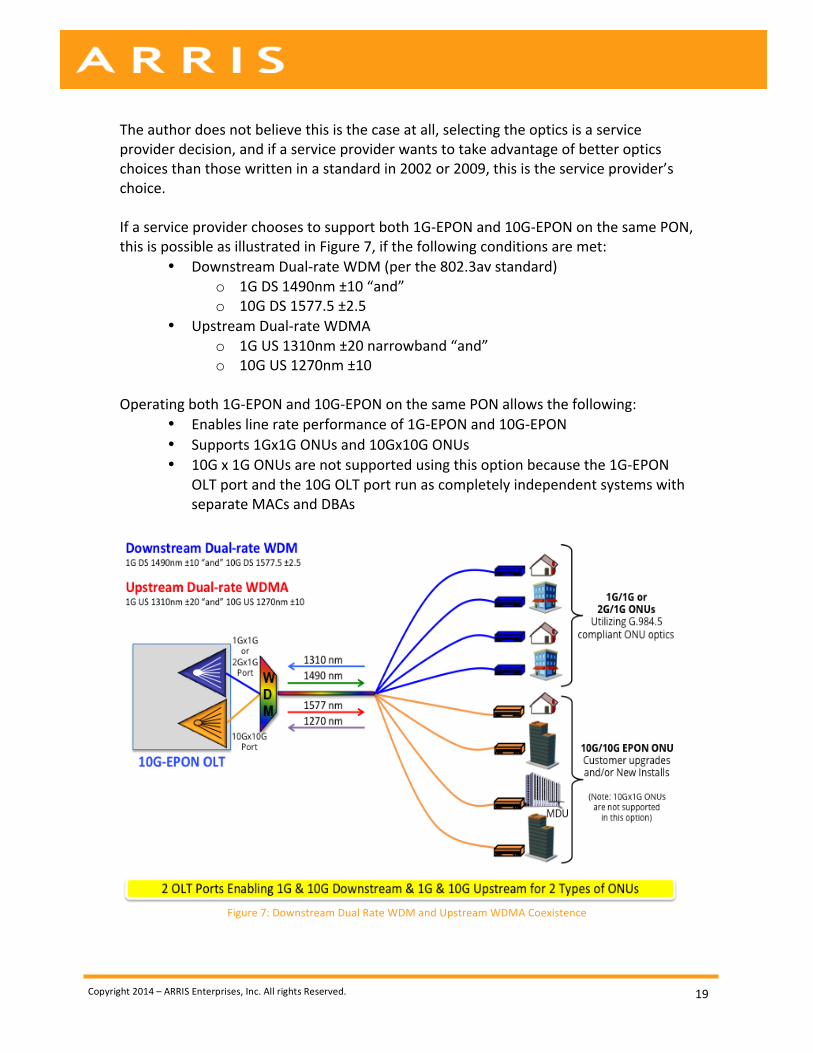
The author does not believe this is the case at all, selecting the optics is a service provider decision, and if a service provider wants to take advantage of better optics choices than those written in a standard in 2002 or 2009, this is the service provider’s choice. If a service provider chooses to support both 1G-‐EPON and 10G-‐EPON on the same PON, this is possible as illustrated in Figure 7, if the following conditions are met:
• Downstream Dual-‐rate WDM (per the 802.3av standard) o 1G DS 1490nm ±10 “and” o 10G DS 1577.5 ±2.5
• Upstream Dual-‐rate WDMA o 1G US 1310nm ±20 narrowband “and” o 10G US 1270nm ±10
Operating both 1G-‐EPON and 10G-‐EPON on the same PON allows the following:
• Enables line rate performance of 1G-‐EPON and 10G-‐EPON • Supports 1Gx1G ONUs and 10Gx10G ONUs • 10G x 1G ONUs are not supported using this option because the 1G-‐EPON
OLT port and the 10G OLT port run as completely independent systems with separate MACs and DBAs
Figure 7: Downstream Dual Rate WDM and Upstream WDMA Coexistence
Copyright 2014 – ARRIS Enterprises, Inc. All rights Reserved.
20
The above Figure 7 illustrates coexistence of EPON and 10G-‐EPON over the same fiber using WDM. In this case, two physical ports are used on the same OLT, one for either 1Gx1G EPON or 2Gx1G Turbo Mode EPON and the second port for 10Gx10G. If this option is used by an operator, a 10Gx1G ONU could not be used because the EPON and 10G-‐EPON ports run independently having two MAC (media access controllers) and two DBAs (Dynamic Bandwidth Allocation) systems and no communication channel between these two systems. The WDM / WDMA option is similar to how GPON and XG-‐PON1 would coexist, or perhaps a better example this would be similar to GPON and the future NG-‐PON2, because NG-‐PON2 is capable of 10G x 10G, whereas XG-‐PON1 is 10G x 2.5G. Summary of WDM and WDMA Coexistence using the EPON Family:
• Advantages: o Enables the service provider to use the same fiber to offer services at
different data rates o Enables separate networks to operate independently on the same
fiber o Lower speed ONUs do not impact the speed of ONUs on the high-‐
speed network o Enables each network to operate at its maximum capacity
• Disadvantages:
o Requires two different OLT ports to support two different types of ONUs (1G x 1G “or” 2G x 1G and also 10G x 10G)
o This WDM and WDMA option does not support 10G x 1G ONUs o Requires 2X ports compared to the TDMA option o OLT resources increase facility space and power requirements
WDM and WDMA Mixed Mode Coexistence using the EPON Family
As stated in the section above, 10G-‐EPON standards clearly defined support for WDM (wavelength division multiplexing) coexistence on the downstream, which is referred to as downstream dual-‐rate WDM allowing the OLT to transmit both 10 Gb/s and 1 Gb/s downstream signals [3]. Additionally the paper has discussed that a service provider could select to deploy EPON and 10G-‐EPON using WDM (wavelength division multiplexing) coexistence, in a similar manner to the GPON family of standards (GPON, XG-‐PON1, and NG-‐PON2). However, when selecting the WDM and WDMA option, the ability to deploy three different ONU types is not supported and therefore support for 10G x 1G ONUs is not possible. This section introduces the use of WDM for the downstream and WDMA Mixed Mode for the upstream.
Copyright 2014 – ARRIS Enterprises, Inc. All rights Reserved.
21
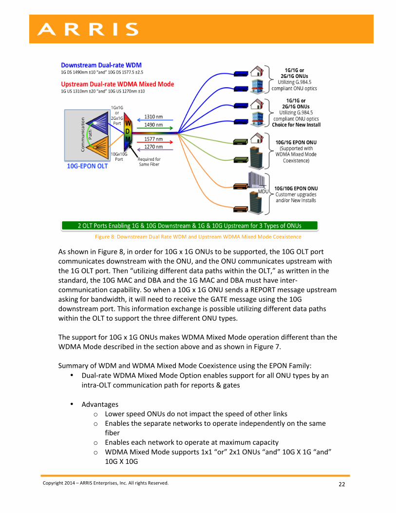
The IEEE clearly defined support for the TDMA mode for the upstream transmission, which is described in the following sections. The use of WDM or WDMA for the upstream transport was not clearly defined, though the IEEE 10G-‐EPON specification does mention different OLT configurations that could enable such functions. Specifically, IEEE standard 802.3av-‐2009 AMENDMENT TO IEEE Standard 802.3-‐2008: CSMA/CD on page 96 states, “Asymmetric-‐rate operation for transmit and receive data paths at the OLT, utilizing transmit path functionality of the XGMII defined in Clause 46 and receive path functionality of the GMII defined in Clause 35.” The IEEE states the “the parallel use of the GMII and XGMII” are supported, in other words, GMII (1G) and XGMII (10G). It also states on page 96, that utilizing different data paths within the OLT supports “Coexistence of various ONU types by utilizing different data paths within the OLT”. It is this last statement written in the 10G-‐EPON standard that proponents of using the WDMA Mixed Mode could point to for support. If a service provider wishes to point to the specification for support of WDMA and WDMA Mixed Mode options, these references on page 83 and page 96 may provide such support. However, service providers may select WDM / WDMA upstream options regardless of explicit text written in the standard. Narrowband optics are required for ONUs that use 1 Gb/s upstream transport when deploying the WDMA options for coexistence of EPON and 10G-‐EPON on the same fiber, and the use of narrowband is a likely choice anyway for cable operator deployments. In Figure 8, Upstream WDMA Mixed Mode is utilized, and this supports 10G downstream by 1G upstream ONUs. In the IEEE Standard 802.3av-‐2009, Annex 75A, page 83, it states, “If the OLT supports a single upstream data rate e.g., only 1 Gb/s or 10 Gb/s, the receiver can be designed to handle the designated upstream data rate and line code.” It also states on page 96 that utilizing different data paths within the OLT supports the “Coexistence of various ONU types by utilizing different data paths within the OLT”. In order to support full data rates for both 1G x 1G and 10G x 10G the use of Downstream Dual-‐rate WDM per the standard is required, and if the OLT is configured to support Upstream Dual-‐rate, WDMA is required to use the same fiber. To support 10G by 1G ONUs, Upstream Dual-‐rate WDMA Mixed Mode operation is required, which is supported, as defined in the 10G-‐EPON standard, y utilizing different data paths within the OLT which in turn supports the coexistence of various ONU types on the same fiber. This means that communication of the OLT to ONUs must be at the same data rate for all ONUs, and the communication within the OLT could facilitate various ONU options, such as 10G x 1G ONUs.
Copyright 2014 – ARRIS Enterprises, Inc. All rights Reserved.
22
Figure 8: Downstream Dual Rate WDM and Upstream WDMA Mixed Mode Coexistence
As shown in Figure 8, in order for 10G x 1G ONUs to be supported, the 10G OLT port communicates downstream with the ONU, and the ONU communicates upstream with the 1G OLT port. Then “utilizing different data paths within the OLT,” as written in the standard, the 10G MAC and DBA and the 1G MAC and DBA must have inter-‐communication capability. So when a 10G x 1G ONU sends a REPORT message upstream asking for bandwidth, it will need to receive the GATE message using the 10G downstream port. This information exchange is possible utilizing different data paths within the OLT to support the three different ONU types. The support for 10G x 1G ONUs makes WDMA Mixed Mode operation different than the WDMA Mode described in the section above and as shown in Figure 7. Summary of WDM and WDMA Mixed Mode Coexistence using the EPON Family:
• Dual-‐rate WDMA Mixed Mode Option enables support for all ONU types by an intra-‐OLT communication path for reports & gates
• Advantages
o Lower speed ONUs do not impact the speed of other links o Enables the separate networks to operate independently on the same
fiber o Enables each network to operate at maximum capacity o WDMA Mixed Mode supports 1x1 “or” 2x1 ONUs “and” 10G X 1G “and”
10G X 10G
Copyright 2014 – ARRIS Enterprises, Inc. All rights Reserved.
23
• Disadvantages
• Requires two OLT Ports in the headend to support 3 ONU options: o EPON or Turbo EPON o 10G x 1G ONUs o 10G x 10G ONUs
• Requires 2X Ports compared to the TDMA option • OLT resources increase facility space and power requirements • Cost is a major factor
Time Division Multiple Access (TDMA) Coexistence: All PON systems work today by allocating time slots for end users to transmit upstream data, as this is a requirement to avoid collisions in the optical domain. The IEEE 10G EPON takes this a step further by allowing different data rate devices to share the same PON port by allocating separate time slots, called Time Division Multiple Access (TDMA) coexistence. The IEEE defined 802.3av 10G EPON to support 10 Gb/s downstream and 10 Gb/s upstream, while still supporting the legacy 802.3ah EPON 1 Gb/s downstream and upstream and adding a combination of the two, 10 Gb/s downstream and 1 Gb/s upstream. In most industries this is called backward compatibility, whereby devices which use a previous standard are supported on the newly defined standards and supporting systems. The following section examines numerous telecommunication examples of backward compatibility that define previous and current versions of networking devices to run on the same network and using the “same” access / aggregation layer elements. The FSAN / ITU-‐T defined PON technologies to date have not allowed backward compatibility, but rather required the service provider to run a completely parallel system on either separate fibers or separate wavelengths to support the previous and current standards. FSAN and ITU-‐T PON systems require separate OLT ports to accomplish this, and in most cases require separate line cards and likely chassis to enable coexistence. Again, the IEEE PON standard is completely different, allowing the previous PON standard 802.3ah (1G-‐EPON) to be supported in the new 802.3av standard (10G-‐EPON). In addition, 802.3av defines methods that enable three ONU types to be supported from one OLT port, and in this section the use of TDMA coexistence is explored. As illustrated in Figure 9, a 10G OLT can support TDMA coexistence of multiple PON data rates on a single OLT port by allocating different upstream time-‐slots to each ONU. The data rate of the upstream link will change from ONU to ONU and is determined by the device type transmitting upstream at that time. As far as the downstream transport is considered, this is unchanged from the previous WDMA and WDMA mixed model options. If the service provider desires to support 1G or 2G downstream ONUs, then the
Copyright 2014 – ARRIS Enterprises, Inc. All rights Reserved.
24
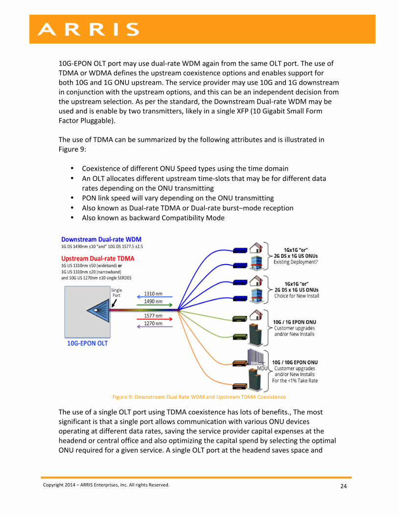
10G-‐EPON OLT port may use dual-‐rate WDM again from the same OLT port. The use of TDMA or WDMA defines the upstream coexistence options and enables support for both 10G and 1G ONU upstream. The service provider may use 10G and 1G downstream in conjunction with the upstream options, and this can be an independent decision from the upstream selection. As per the standard, the Downstream Dual-‐rate WDM may be used and is enable by two transmitters, likely in a single XFP (10 Gigabit Small Form Factor Pluggable). The use of TDMA can be summarized by the following attributes and is illustrated in Figure 9:
• Coexistence of different ONU Speed types using the time domain • An OLT allocates different upstream time-‐slots that may be for different data
rates depending on the ONU transmitting • PON link speed will vary depending on the ONU transmitting • Also known as Dual-‐rate TDMA or Dual-‐rate burst–mode reception • Also known as backward Compatibility Mode
Figure 9: Downstream Dual Rate WDM and Upstream TDMA Coexistence
The use of a single OLT port using TDMA coexistence has lots of benefits., The most significant is that a single port allows communication with various ONU devices operating at different data rates, saving the service provider capital expenses at the headend or central office and also optimizing the capital spend by selecting the optimal ONU required for a given service. A single OLT port at the headend saves space and
Copyright 2014 – ARRIS Enterprises, Inc. All rights Reserved.
25
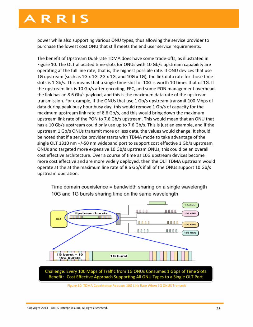
power while also supporting various ONU types, thus allowing the service provider to purchase the lowest cost ONU that still meets the end user service requirements. The benefit of Upstream Dual-‐rate TDMA does have some trade-‐offs, as illustrated in Figure 10. The OLT allocated time-‐slots for ONUs with 10 Gb/s upstream capability are operating at the full line rate, that is, the highest possible rate. If ONU devices that use 1G upstream (such as 1G x 1G, 2G x 1G, and 10G x 1G), the link data rate for those time-‐slots is 1 Gb/s. This means that a single time-‐slot for 10G is worth 10 times that of 1G. If the upstream link is 10 Gb/s after encoding, FEC, and some PON management overhead, the link has an 8.6 Gb/s payload, and this is the maximum data rate of the upstream transmission. For example, if the ONUs that use 1 Gb/s upstream transmit 100 Mbps of data during peak busy hour busy day, this would remove 1 Gb/s of capacity for the maximum upstream link rate of 8.6 Gb/s, and this would bring down the maximum upstream link rate of the PON to 7.6 Gb/s upstream. This would mean that an ONU that has a 10 Gb/s upstream could only use up to 7.6 Gb/s. This is just an example, and if the upstream 1 Gb/s ONUs transmit more or less data, the values would change. It should be noted that if a service provider starts with TDMA mode to take advantage of the single OLT 1310 nm +/-‐50 nm wideband port to support cost effective 1 Gb/s upstream ONUs and targeted more expensive 10 Gb/s upstream ONUs, this could be an overall cost effective architecture. Over a course of time as 10G upstream devices become more cost effective and are more widely deployed, then the OLT TDMA upstream would operate at the at the maximum line rate of 8.6 Gb/s if all of the ONUs support 10 Gb/s upstream operation.
Figure 10: TDMA Coexistence Reduces 10G Link Rate When 1G ONUS Transmit
Copyright 2014 – ARRIS Enterprises, Inc. All rights Reserved.
26
• Advantages: Allows services providers to allow CPE with different data rates (and there cost points) to share the same access layer port at the OLT. This saves OLT port costs while reducing space, power, and cooling requirements. TDMA coexistence also provides a migration path to a configuration where all CPE devices operate at the maximum data rate.
o Support a mix and match of ONUs § 10G OLT may support 1G x 1G ONUs or 2G x 1G ONUs § 10G OLT may support 10G x 1G ONUs § 10G OLT may support 10G x 10G ONUs
o Supports any combination of the above o 10G link has more than enough capacity and time slots to accommodate
lower bit rate 1G ONUs o Supports all ONU options from a single OLT port o Very cost effective single port supports all speeds and devices o Allows high bit rate services to be offered, and these can be offered cost-‐
effectively even with low take rates
• Disadvantages: Sharing the same wavelength band with higher and lower data rate ONUs requires an OLT port to time-‐share the link, and the result is that the full upstream capacity of the system is not utilized when the lower speed ONUs are transmitting. A 10G EPON allows 1 Gb/s and 10Gb/s upstream devices to share the same 10G OLT Port, and this represents a 10:1 difference in data rates.
o Lower bit rate upstream (1G) devices reduces the overall 10G Link throughput when transmitting
o Example: 100 Mbps of 1G ONU upstream traffic removes 1 Gbps of Network Capacity
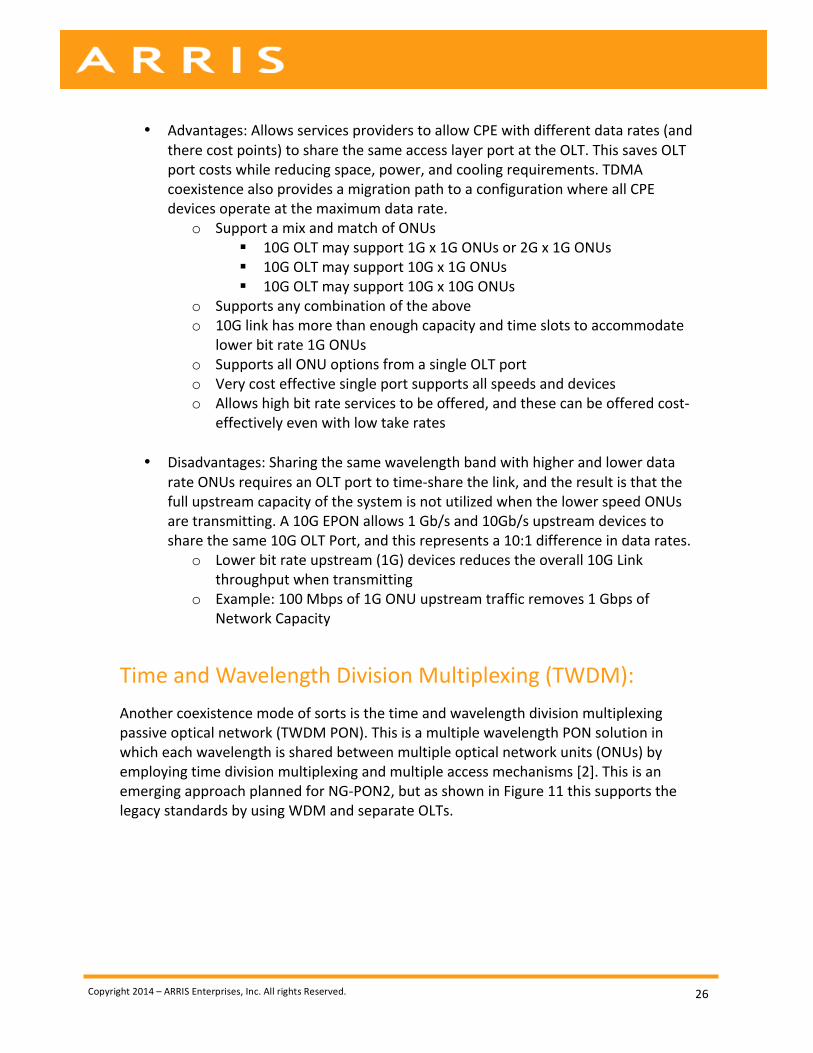
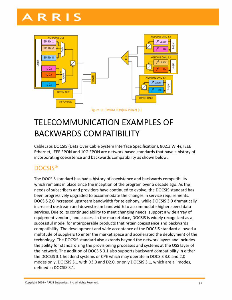
Time and Wavelength Division Multiplexing (TWDM): Another coexistence mode of sorts is the time and wavelength division multiplexing passive optical network (TWDM PON). This is a multiple wavelength PON solution in which each wavelength is shared between multiple optical network units (ONUs) by employing time division multiplexing and multiple access mechanisms [2]. This is an emerging approach planned for NG-‐PON2, but as shown in Figure 11 this supports the legacy standards by using WDM and separate OLTs.
Copyright 2014 – ARRIS Enterprises, Inc. All rights Reserved.
27
Figure 11: TWDM PON(XG-‐PON2) [1]
TELECOMMUNICATION EXAMPLES OF BACKWARDS COMPATIBILITY CableLabs DOCSIS (Data Over Cable System Interface Specification), 802.3 Wi-‐Fi, IEEE Ethernet, IEEE EPON and 10G EPON are network based standards that have a history of incorporating coexistence and backwards compatibility as shown below.
DOCSIS® The DOCSIS standard has had a history of coexistence and backwards compatibility which remains in place since the inception of the program over a decade ago. As the needs of subscribers and providers have continued to evolve, the DOCSIS standard has been progressively upgraded to accommodate the changes in service requirements. DOCSIS 2.0 increased upstream bandwidth for telephony, while DOCSIS 3.0 dramatically increased upstream and downstream bandwidth to accommodate higher speed data services. Due to its continued ability to meet changing needs, support a wide array of equipment vendors, and success in the marketplace, DOCSIS is widely recognized as a successful model for interoperable products that retain coexistence and backwards compatibility. The development and wide acceptance of the DOCSIS standard allowed a multitude of suppliers to enter the market space and accelerated the deployment of the technology. The DOCSIS standard also extends beyond the network layers and includes the ability for standardizing the provisioning processes and systems at the OSS layer of the network. The addition of DOCSIS 3.1 also supports backward compatibility in either the DOCSIS 3.1 headend systems or CPE which may operate in DOCSIS 3.0 and 2.0 modes only, DOCSIS 3.1 with D3.0 and D2.0, or only DOCSIS 3.1, which are all modes, defined in DOCSIS 3.1.
Copyright 2014 – ARRIS Enterprises, Inc. All rights Reserved.
28
IEEE Wi-‐Fi (802.11) Wi-‐Fi® is a standard that has been implemented in an interoperable manner. Through four versions of IEEE 802.11 Wi-‐Fi standards, including 802.11 a/b/g/n, coexistence and backwards compatibility have been supported in all cases, and a parallel network model has not been required.
IEEE Ethernet 802.3 IEEE Ethernet is a standard where evolution towards higher speeds has been carefully implemented to ensure coexistence and backwards compatibility with existing equipment. Through the three versions of the Ethernet standard, including 10 Mbps (Ethernet), 100 Mbps (FastE), and 1 Gbps (GigE), coexistence and backwards compatibility have been supported and a parallel network has not been required to support the evolution. The use of auto-‐negotiation also allows a network to operate at the highest data rate that is mutually supportable across the network-‐attached devices.
IEEE EPON and 10G EPON (802.3ah and 802.3av) The IEEE standard organization has demonstrated an excellent historical understanding of the value of coexistence and backwards compatibility. This has extended to the IEEE EPON program whereby the latest version of the EPON standard defining 10Gbps EPON defines coexistence and backwards compatibility with the earlier versions of EPON.
Fibre Channel The Fibre Channel specification used for high capacity data storage transport generally requires systems to be backward compatible with at least two previous versions.
G.fast The G.fast specification supporting high-‐bit-‐rate services over copper twisted pair and is positioned as the version to replace VDSL2 for very short loop links. The G.fast standard defines backward compatibility with VDSL to enable a smooth transition. This will allow a telco to place the G.Fast aggregator in the field and not require the customer premise device, which is VDSL2, to be changed. This is known as fall back mode or backward compatibility.
Summary of Backward Compatibility The IEEE 10G EPON standard’s support for Downstream Dual-‐rate WDM and Time Division Multiple Access (TDMA) allows a 10G OLT with a single port to support 1G-‐EPON and 10G-‐EPON ONUs; this is a clear example of backward compatibility. This
Copyright 2014 – ARRIS Enterprises, Inc. All rights Reserved.
29
approach of defining the new access layer network element to support previous and current standards is used extensively in the telecommunication Industry as cited in this section. The 10G EPON success in the market place to date is likely because of this key feature, as operators recognize capital and operational savings.
TYPES OF PON NETWORK ARCHITECTURES CENTRALIZED AND DISTRIBUTED (CAA & DAA) The topic of Centralized Access Architecture (CAA) and Distributed Access Architecture (DAA) is of major interest these days in the cable networking space. What are CAA and DAA? Centralized access architecture retains all of the MAC and PHY layer functions used for network access layer elements in the service provider’s facility. The distributed access architecture places the access layer MAC and PHY layers or just the PHY layer in the outside plant or MDU location. To date nearly all of the cable deployments utilize the centralized access architecture, which keeps the access layer (DOCSIS) MAC and PHY in the service provider facility while maintaining a transparent outside plant. This is also the case with PON deployments in the cable and telco space: the OLT PON MAC and PHY are located in the facility enabling the outside plant (OSP) or optical distribution network (ODN) to remain passive and transparent. This is not at all the case with telcos that are leveraging their legacy copper investment by deploying Fiber-‐to-‐the-‐Node (FTTN) and using VDSL2 technology to reach homes via existing copper. This is a Distributed Access Architecture (DAA). The FTTN and VDSL2 architecture must place the MAC and PHY layer at the remote FTTN to copper node location to achieve the high capacity data rates possible over copper. The telco FTTN + VDSL architecture must be a DAA because the copper access component is a point-‐to-‐point access architecture, and each copper line must be terminated close to the customer in order to maximize the copper’s transport capacity. A Centralized Access Architecture is not an option here. Passive Optical Networks (PONs) have had options for supporting remote OLTs since as early as 2002, but placing the OLT MAC and PHY in a remote node enclosure did not garner significant market share as most service providers prefer a centralized OLT using a passive optical distribution network (ODN), which keeps the outside plant as simple as possible for as long as possible by keeping it passive and transparent. However, placing the OLTs in the HE/CO facility may restrict the reach between the HE/CO and end users
Copyright 2014 – ARRIS Enterprises, Inc. All rights Reserved.
30
and/or reduce the split ratio and number of subscribers served per OLT port. The benefits of using a remote OLT include the following:
1. Increase the distance between the service provider HE/CO & subscriber serving area
2. Increase the split ratio to maximize subscribers served per OLT port 3. Increase the distance and subscribers served per OLT port 4. Collapse facilities or enable facilities to become passive 5. Segmentation for a service group to extend the use of 10G-‐EPON and not move
to the expensive TWDM PON architecture at the OLT or ONU 6. Lower CPE optical costs (overall costs to be assessed to determine benefit)
The section will examine the Centralized Access Architecture for PON as well as the Distributed Access Architecture for PON. In recent years there has been innovation to extend the reach of the centralized OLT architecture while keeping the OSP/ODN transparent, and this is a new class of PON architecture using PON Extenders. The PON Extender is a powered device that could be placed in a facility, cabinet, or strand mounted node enclosure; the PON extender does not contain the OLT MAC and PHY, making this a Centralized Access Architecture. The PON Extender may allow the OLT at the facility to use CWDM or DWDM optics to the PON Extender. The PON Extender performs an optical-‐to-‐electrical-‐to-‐optical (O-‐E-‐O) conversion and then the standard PON wavelengths are used at the customer facing side of the PON Extender, as shown in Figure 13. All of the benefits and drivers to the Remote OLT architecture can be achieved with the PON extender architecture without placing the OLT PON MAC and PHY in the outside plant.
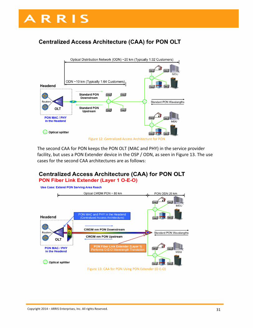
9.1. Centralized Access Architecture (CAA) – PON: There are two Centralized Access Architectures for PON. The first is the traditional approach of placing the PON OLTs in the service provider’s facility and having a completely passive OSP / ODN, as seen in Figure 12.
Copyright 2014 – ARRIS Enterprises, Inc. All rights Reserved.
31
Figure 12: Centralized Access Architecture for PON
The second CAA for PON keeps the PON OLT (MAC and PHY) in the service provider facility, but uses a PON Extender device in the OSP / ODN, as seen in Figure 13. The use cases for the second CAA architectures are as follows:
Figure 13: CAA for PON Using PON Extender (O-‐E-‐O)
Copyright 2014 – ARRIS Enterprises, Inc. All rights Reserved.
32
Summary of Centralized Access Architecture (CAA) – PON:
• Advantages: o Complex systems are not located in the ODN / OSP (only at the facility
and CPE) o The PON OLT MAC and PHY are located at the service provider facility o The ODN is entirely transparent (just passives or with PON Extender O-‐E-‐
O) o CAA with PON extender has the following use cases and advantages
§ Increase distance between service provider facility & subscriber serving area
§ Increase split ratio to maximize subscribers served per OLT port § Increase Distance and Subscribers Served per OLT port § Collapse facilities or enable facilities to become passive § Segmentation for a Service Group to Extend the Use of 10G-‐EPON
and not move to the expensive TWDM PON architecture at the OLT or ONU
§ Lower CPE optical costs (overall costs to be assessed to determine benefit)
o Utilized a single data network from the facility though the ODN to CPE
• Disadvantages: o Consumes more space / power in headend compared to DAA o PON Extender architecture now requires remotely powered devices in
the ODN
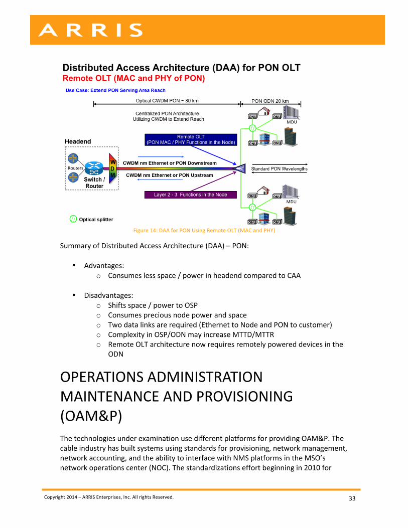
Distributed Access Architecture (DAA) – PON The distributed access architecture for PON places the MAC and PHY of the OLT in the outside plant (OSP) / optical distribution network (ODN) As shown in Figure 14. The DAA features are listed below:
• The OLT is located in the ODN (strand mounted or in a cabinet) and is referred to as a Remote OLT
• The ODN is an active architecture (not transparent or passive) • The connection from the service provider facility to the Remote OLT is a Layer 2
or Layer 3 Link via P2P Optical Ethernet or PON
Copyright 2014 – ARRIS Enterprises, Inc. All rights Reserved.
33
Figure 14: DAA for PON Using Remote OLT (MAC and PHY)
Summary of Distributed Access Architecture (DAA) – PON:
• Advantages: o Consumes less space / power in headend compared to CAA
• Disadvantages:
o Shifts space / power to OSP o Consumes precious node power and space o Two data links are required (Ethernet to Node and PON to customer) o Complexity in OSP/ODN may increase MTTD/MTTR o Remote OLT architecture now requires remotely powered devices in the
ODN
OPERATIONS ADMINISTRATION MAINTENANCE AND PROVISIONING (OAM&P) The technologies under examination use different platforms for providing OAM&P. The cable industry has built systems using standards for provisioning, network management, network accounting, and the ability to interface with NMS platforms in the MSO’s network operations center (NOC). The standardizations effort beginning in 2010 for
Copyright 2014 – ARRIS Enterprises, Inc. All rights Reserved.
34
DOCSIS provisioning of EPON (DPoE) leverages the MSO’s existing back office systems; include provisioning, fault management, and IPDR. This is another factor as to why MSOs should select EPON for PON.
CONCLUSIONS The cable operator’s decision between deploying PONs based upon the EPON family of standards or the GPON family of standards will be dependent upon several factors. Researching the key drivers of which data PON technology an MSO should select was a major item of analysis in this paper. The data PON technology choices include: EPON, 10G-‐EPON, GPON, XG-‐PON1, or NG-‐PON2. We are recommending that cable operators use IEEE 10G-‐EPON OLTs as this will exceed the data capacity of their competition and even meet future competitive challenges. Cable operators can select from multiple ONU options to meet cost objectives or service tier requirements when selecting a 10G-‐EPON OLT. 10G-‐EPON can also be used in conjunction with RFoG if desired. The reasons for selecting 10G-‐EPON over the other data PON technologies is as follows:
1. The capacity of 10G-‐EPON is already 10G symmetrical, but also supports multiple data rates.
2. A 10G-‐EPON OLT may support the following data rates from a single OLT Port: a. 1G x 1G or 2G x 1G (Turbo Mode) b. 10G x 1G c. 10G x 10G
3. The 10G EPON OLT supports the functions of 3 types of GPON Family OLTs. 4. The 10G EPON OLT supports 4 types of ONUs: (1x1 or 2x1, 10x1, 10x10). 5. DPoE is already defined and deployed, supporting back office integration and
interoperability between vendors using existing back-‐office systems. 6. 10G-‐EPON provides a choice: 1) TDMA for backward compatibility or 2) WDMA
to maximize throughput. 7. In the future when TWDM PON is needed, it is believed that NG-‐EPON will
support similar functions. 8. 10G-‐EPON could also support multiple waves of 10G PONs on the same fiber to a
serving area in conjunction with the PON Extender, and the PON Extender could be used to split service groups, enabling more 10G capacity, while not requiring TWDM Tunable ONUs.
Another area that cable operators will begin to assess is the type of PON access network architecture, and here the choices are Centralized Access Architecture (CAA) for PON or Distributed Access Architecture (DAA) for PON. Our recommendation is to consider CAA for PON OLT. With CAA, the MAC and PHY functions of the PON OLT remain in the facility, and the OSP is all passive or transparent. Additionally, if there were situations where a Remote OLT would be considered the use of a PON extender would allow the
Copyright 2014 – ARRIS Enterprises, Inc. All rights Reserved.
35
PON OLT to remain in the headend and achieve the key benefit of the remote OLT. The use of the PON Extender may be used for the following reasons:
1. Increase Distance between Service Provider (SP) Facility & Subscriber Serving Area
2. Increase Split Ratio to Maximize Subscribers Served per OLT Port 3. Increase Distance and Subscribers Served per OLT Port 4. Collapse Facilities or Enable Facilities to become Passive 5. Segmentation for a Service Group to Extend the Use of 10G-‐EPON and not move
to the expensive TWDM PON architecture at the OLT or ONU 6. Lower CPE optical costs (overall costs to be assessed to determine benefit)
ACKNOWLEDGEMENTS The author would like to especially thank Mr. Steve Hersey and Mrs. Janet Bean for their contributions to this paper and their fifteen years of service in the PON industry. Their extensive experience began with FSAN / ITU-‐T based solutions and has extended to the IEEE EPON and CableLabs DPoE standards.
MEET ONE OF OUR EXPERTS: Mike Emmendorfer Mike Emmendorfer serves as Senior Director, Systems Engineering and Architecture, in the Office of the CTO at ARRIS. In this role, he is responsible for forward-‐looking architecture and strategy to determine the viability of new products and technologies. Projects have included DOCSIS enhancements, EPOC, EPON, Metro Ethernet Forum, Wireless, RFoG, Remote Access Architectures, and IPTV. Recently, Mike was lead author in a series of ARRIS publications, presented at numerous conferences spanning the globe during 2011 and 2012 that defined the next generation of DOCSIS, which later became DOCSIS 3.1. The final release of the “Next Generation – Cable Access Network (NG–CAN)” series of papers and publications in February 2012 defined the core features set for what later become DOCSIS 3.1. Later, in May 2012 for the NCTA – Cable Show, Mike teamed up with technical leaders from Cisco, Intel, and Motorola to co-‐author “Mission is Possible: An Evolutionary Approach to Gigabit-‐Class DOCSIS”, and it was this joint paper that launched DOCSIS 3.1.
Copyright 2014 – ARRIS Enterprises, Inc. All rights Reserved.
36
REFERENCES 1) Progress in Optical Access Standards, Frank Effenberger, Rapporteur Q2/15, VP
Access R&D, Futurewei, Joint ITU/IEEE Workshop on Ethernet -‐ Emerging Applications and Technologies (Geneva, Switzerland, 22 September2012)
2) Recommendation ITU-‐T G.989.1 -‐ 40-‐Gigabit-‐capable passive optical networks (NG-‐PON2): General requirements.
3) IEEE standards 802.3av-‐2009 AMENDMENT TO IEEE Std 802.3-‐2008
Copyright 2014 – ARRIS Enterprises, Inc. All rights Reserved.
37
ABBREVIATIONS & ACRONYMS 10G-‐EPON 10 Gigabit Ethernet PON APON ATM (Asynchronous Transfer Mode) Passive Optical Network BPON Broadband-‐Passive Optical Network CAA Centralized Access Architecture CESoP Circuit Emulation Service over Packet CMTS Cable Modem Termination System CO Central Office CWDM Coarse Wave Division Multiplexed DAA Distributed Access Architecture DOCSIS Data Over Cable System Interface Specification DPG DOCSIS Provisioning of GPON DPoE DOCSIS Provisioning of EPON EPON Ethernet Passive Optical Network (aka GE-‐PON) FEC Forward Error Correction FSAN Full Service Access Network FTTH Fiber to the Home FTTN Fiber to the Node FTTP Fiber to the Premise FTTx Fiber to The x (FTTH Home, FTTB Business, FTTP Premise, FTTC Curb) Gbps Gigabits per Second GEPON Gigabit Ethernet -‐ Passive Optical Network (aka EPON) GPON Gigabit-‐Passive Optical Network HE Heaend HFC Hybrid Fiber Coax HHP Households Passed IEEE Institute of Electrical and Electronics Engineers MAC Media Access Layer Mbps Megabit per Second MDU Multiple Dwelling Unit MSO Multiple System Operator NRZ Non-‐Return-‐to-‐Zero ODN Optical Distribution Network OLT Optical Line Terminal ONT Optical Network Terminal ONU Optical Network Unit OSP Outside Plant P2MP Point-‐to-‐Multipoint PHY Physical Layer PON Passive Optical Network QoS Quality of Service
Copyright 2014 – ARRIS Enterprises, Inc. All rights Reserved.
38
RFoG Radio Frequency over Glass (aka: Radio Frequency PON) TDMA Time Division Multiple Access TWDM Time and wavelength division multiplexed passive optical network US Upstream WDM Wavelength Division Multiplexing WDM-‐PON Wavelength Division Multiplexing PON ©ARRIS Enterprises, Inc. 2014 All rights reserved. No part of this publication may be reproduced in any form or by any means or used to make any derivative work (such as translation, transformation, or adaptation) without written permission from ARRIS Enterprises, Inc. (“ARRIS”). ARRIS reserves the right to revise this publication and to make changes in content from time to time without obligation on the part of ARRIS to provide notification of such revision or change.


![323970 1 En BookBackmatter 223. - Springer978-3-319-54224-9/1.pdf · 49. O. Haran, EPON vs. GPON, A practical comparison [html] (2005). . com/design/communications-design/40Q9354/EPON-vs-GPON-A-Practical-Comparison](https://static.documents.pub/doc/80x56/5b8868aa7f8b9a435b8dc896/323970-1-en-bookbackmatter-223-springer-978-3-319-54224-91pdf-49-o-haran.jpg)


