Comparison between the matrix method andthe coupled-wave method in the analysis of Bragg
reflector structures
Boo-Gyoun Kim* and Elsa Garmire
Center for Laser Studies, University of Southern California, Los Angeles, California 90089-1112
Received December 31, 1990; revised manuscript received July 16, 1991; accepted August 18, 1991
We compare the reflectivity spectrum and phase-change spectrum of Bragg reflectors obtained by the matrixmethod and the coupled-wave method. We show that the results obtained by the two methods agree well gener-ally and the discrepancy between the results obtained by the two methods increases as the fractional refractive-index difference between adjacent layers increases and (or) the average absorption loss increases because of theapproximations inherent in the coupled-wave method for the analysis of multiple dielectric layers.
INTRODUCTION
Periodic optical media and stratified periodic optical struc-tures play an important role in a number of applicationsin optics. Recent developments in crystal-growing tech-niques have made it possible to grow high reflectanceBragg mirrors or Bragg reflectors (BR's) monolithi-cally.1 Integration of BR's has permitted important opti-cal devices, such as vertically emitting lasers2 andmicroresonators, to be monolithically grown.3 Large re-flectivity changes of 0.38 were demonstrated with a non-linear BR that operates on saturable absorption owing tothe band-filling nonlinearity.4
There are two important theoretical methods used toanalyze the distributed-feedback structures. One is thematrix method, and the other is the coupled-wave method.The use of the matrix method in the study of the propaga-tion of plane electromagnetic waves through a stratifiedmedium is well known in optics.5 However, it is difficultto obtain simple analytic expressions of the reflectancespectrum for stratified periodic structures when a matrixmethod is used. The coupled-wave method has long beenused to analyze the characteristics for a periodic layeredmedium because it gives simple analytic expressions forthe reflectivity spectrum of a BR.6 However, using thecoupled-wave method in its simplest form we assume thatthe beam is incident upon the distributed-feedback struc-ture from a medium with an average refractive index ofthe distributed-feedback structure. This conditionmeans that for the coupled-wave method the effect ofend reflections occurring from the boundaries of thedistributed-feedback structure is usually ignored.
We compare theories for BR's in the simultaneouspresence of refractive-index modulation and absorptionmodulation by using both the matrix method and thecoupled-wave method. For the sake of simplicity, we con-sider only the case of normal incidence. We show that, ingeneral, the results obtained by the matrix method andthe coupled-wave method agree well for the reflectanceand the phase-change spectra as a function of detuning.Also, we show that the difference between the results by
the two methods increases as the fractional refractive-index difference between adjacent layers increases and(or) the absorption loss increases because of the approxi-mations inherent in the coupled-wave method.
MATRIX METHOD
Consider the structure as shown in Fig. 1.field in the ith layer can be represented by
The electric
Ei = {Ei+ exp[-iki(z - di-,)] + Ei-
x exp[iki(z - di_1)]}exp[i(,wt)], (1)
where Ei+ and Ei- represent the electric-field amplitudesof waves propagating in the forward and the backward di-rections, respectively. After imposition of the continuityof tangential components of E and H at the interface sepa-rating the ith and the (i + 1)th layers and some matrixmanipulations, the following matrix equation results7 :
where Ai = di - di-,, AO = 0, i = kiAi, ki = koni; n isthe complex refractive index of ith layer, and ko is thepropagation constant in free space. We can representEq. (2) as
Ei- E +1
where
S= 1 exp(ij)ti r exp-iti)
ri exp(i3i)exp(- ii) (3)
and r and t represent the amplitude reflection and trans-mission coefficients at the interface separating the ithand the (i + 1)th layers, respectively.
The complex dielectric constant, E(z), as a function of z iswritten as
Efinal
nf ia
ECN-_I Efinal
z-0 di d2 di- d di+, dN-2 dN-1 dN
Fig. 1. Layered structure used in the formulation of the matrixmethod.
These matrix relations can be used to determine thetransmission and the reflection from a layered structureas follows. The electric field across a layer or a boundaryare related, so that we can determine the matrix relationacross the entire structure by multiplying the relevantmatrices together. Assuming that light is incident fromonly one side of the structure, we put Efinal = 0. Thisboundary condition enables us to determine the incidentfields Ein and E i in terms of Efnal:
[E] = SOS1...SNE nj. (4)
Since the incident electric fields E,+ and Ei- are expressedin terms of Ef'nal we can calculate the complex reflectioncoefficient of a multilayer structure r = E-/E IE if weknow the refractive index and absorption coefficient ineach layer. From these data we determine both the re-flectivity and the phase change.
COUPLED-WAVE METHOD
BR's consist of alternating periodic quarter-wavelengthlayers with different refractive indices and absorption co-efficients. In most semiconductors the material with thehigh refractive index has a narrow band gap. Considerthe BR shown in Fig. 2. Since the optical thickness ofeach layer is a quarter of the Bragg wavelength, AB, theratio of the thickness of the layer with high refractive in-dex to the BR period a is given by a = nL/(nh + nL),
where nL and nh represent the low refractive index andhigh refractive index, respectively. For the sake of sim-plicity, we will assume that the layer with high refractiveindex is lossy and the layer with low refractive index istransparent (a = 0).
Since the coupled-wave method considers the periodicvariation of the dielectric constant and the absorption co-efficient as a perturbation that couples the unperturbednormal waves of the structure, we have to calculate theaverage refractive index, nav. of the structure. Since BR's*are composed of alternating periodic quarter-wavelengthlayers with different refractive indices at the Bragg wave-length, one period corresponds to a half-wavelength of themedium with nav at the Bragg wavelength. Thus the av-erage refractive index of a BR is given by
where Eav is the unperturbed part of the dielectric con-stant. The real part AE = (n 2
- nav2)EO and the imagi-
nary part = naveoAOa/27, where AO is the free-spacewavelength of the incident light. Both or and Ae are peri-odic in the z direction.
The usual starting point of the analysis is the waveequation
[V2 + )2/.LE(z)]E(z) = 0. (7)
We express the complex amplitude of the field E(z) as asum of the wave Ef propagating in the positive directionof the z axis and the wave Eb propagating in the negativedirection of the z axis:
where Ef(z) and Eb(z) are slowly varying complex ampli-tudes. It is assumed that the waves interact only throughthe first-order spatial Fourier component of the complexdielectric constant.
We choose the origin of coordinate system z = 0 in themiddle of the layer with low refractive index in order tocalculate the Fourier components of the complex dielectricconstant step as real values.8 Then we add a phase shiftof the fields occurring in a low-refractive-index layerwhose thickness is 1/8 of an optical wavelength to obtaincomparison with the multilayer case. SubstitutingEq. (8) into Eq. (7), using slowly varying envelope ap-proximation, and performing the usual manipulations, 6
where K = sin(air) (nh2 - nLL2 )/(nav Ao) and F =sin(a7r)a/(27r), K is the coupling coefficient due torefractive-index modulation, F is the coupling coefficientdue to absorption modulation, and a is a measure of thedifference of adjacent layer thickness of a BR defined bya = nL/(nh + nL). The detuning is given by a - f3 -
nL nh nLn h nL
nov a a 0 a 0 nov
Z=O h =aA dL= B =(1-a)A
fnL+nh
Fig. 2. Geometry of a BR calculated by the coupled-wave method.
Y
z
E2
n2
Ei
n,in
E+
ni1+1
E T
(5)
E;
ni
Ei
E(Z) = EaV + AE(z) -i(Z), (6)
E(z) = Ef(z)exp(-if3z) + Eb(z)exp(ipz), (8)
B. -G. Kim and E. Garmire
134 J. Opt. Soc. Am. A/Vol. 9, No. 1/January 1992
Eb(0)exp(iknLdL/2) _ Eb(O)exp(iv/4)Ef(0)exp(- iknLdL/2) Ef (0)exp(- i7r/4)
r i == r expt2 = ir. (12)
If the layer sequence is changed (layer 1 has a low refrac-tive index), the reflection coefficient rL is given by
Eb()exp(-iknLdL/2) _ Eb(0)exp(-irr/4)Ef (O)exp(iknLdL/2) Ef (O)exp(i7r/4)
= r exp( = -ir = -rh. (13)2 4 .6
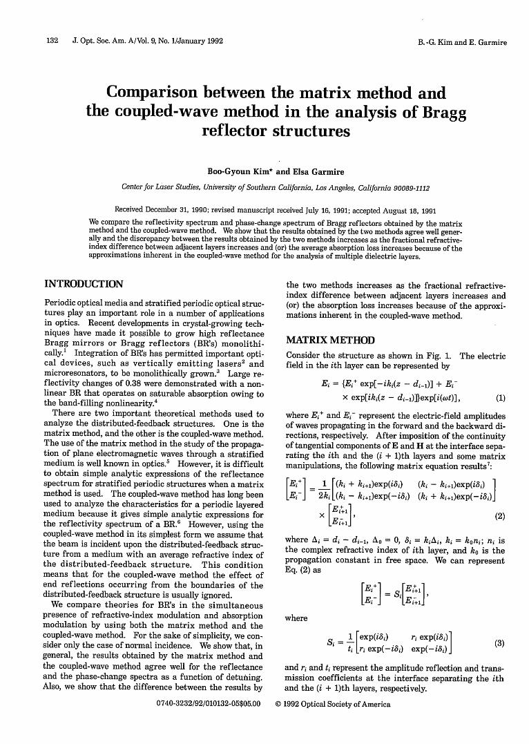
Detuning (L)Fig. 3. Reflectivity spectra obtained by the two methods in thecase of (aL) = 1, KL = 1.1, and An/nL = 0.2. The wavelength isexpressed as a detuning.
0.4
.)
a)
a)
-6 -4 -2 0
Detuning (8L)
Fig. 4. Reflectivity spectra obtained by thicase of (aL) = 1, KL = 1.1 and An/nL = 0.01
(7r/A). The wavelength dependence ofbecause it is of second order. This is capproximations inherent in the coupThis reasoning means that K = sin(amr)
Imposing the boundary condition Ewe obtain an analytical expressioncoefficient:
Eb(O)r Ef(0)
Note that, when the layer sequence is changed, the phaseof the reflection coefficient changes by wr; however themagnitude of the reflection coefficient is the same.
COMPARISON OF THE RESULTS BY THEMATRIX METHOD AND THE COUPLED-WAVEMETHODIn this section we compare the results obtained by the twomethods. We show that, in general, these two resultsagree well for the reflectance and the phase-change spec-tra. Also, we show that the difference of the results bythe two methods increases as the fractional refractive-index difference between adjacent layers, An/nL, increasesand (or) the average absorption loss (defined by (aL) =aaL) increases because of the approximations inherent inthe coupled-wave method for the analysis of multipledielectric layers.
2 4 6 We calculated the reflectivity and the phase change asa function of detuning by using Eq. (2) in the matrix-
a two methods in the method case. In the coupled-wave-method case we used67. Eq. (13). Figures 3 and 4 show the reflectivity spectra in
the case of the same average absorption loss (aL) and cou-fK can be ignored pling strength KL but two different refractive-indexconsistent with the steps. Six layer pairs (n/nL = 0.2) were used in Fig. 3,led-wave method.9 and 17 layer pairs (An/nL = 0.067) were used in Fig. 4.(nh - nL2 )/(nfavAB) .... The asymmetry of the reflectance spectra shown insb(Z) = O at z = L, both results is due to the simultaneous presence offor the reflection the refractive-index modulation and the absorption
modulation.We can clearly see that the difference between the re-
flectance spectra obtained by the two methods is small
This reflection coefficient of Eq. (10) is obtained when1/2 of a quarter-wavelength layer with low refractive in-dex is on top of a multilayer periodic structure that beginswith a high index layer, as shown in Fig. 2. We couldthink of this low-refractive-index layer as a phase shifter.By referring to Eq. (8), we can obtain the reflection coeffi-cient of the BR shown in Fig. 1 when the layer 1 has ahigh refractive index, rh, as
:~
.1) aa)
0.4
0.3
0.2
0.1
Detuning (8L)
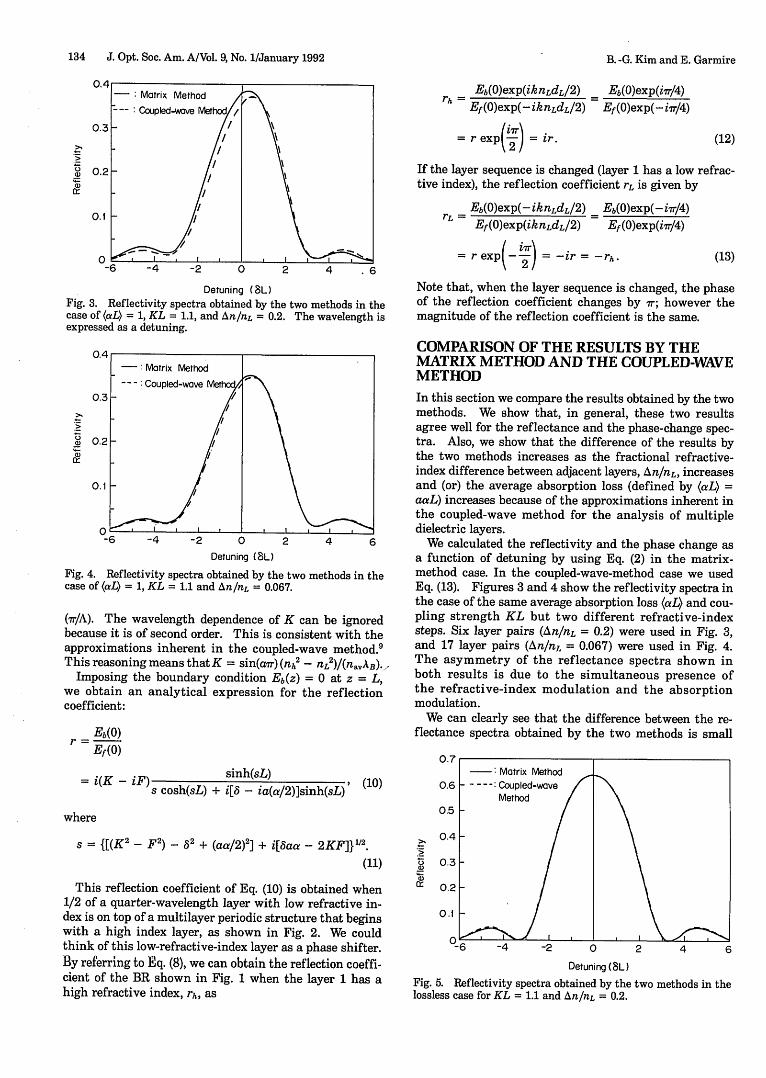
Fig. 5. Reflectivity spectra obtained by the twolossless case for KL = 1.1 and An/n = 0.2.
methods in the
0.4
0.3
. _
a)1)
0.2
-: Matrix Method
--- : Coupledwve Meth
///
- 1'~~~~~
I I
0.1
-E -4 -2 0D
B. -G. Kim and E. Garmire
0-1
Vol. 9, No. 1/January 1992/J. Opt. Soc. Am. A 135
a) 0C:D -0.5-
5- -1.0
- 2.5
-6 -4 -2 0 2 4 6Detuning (L)
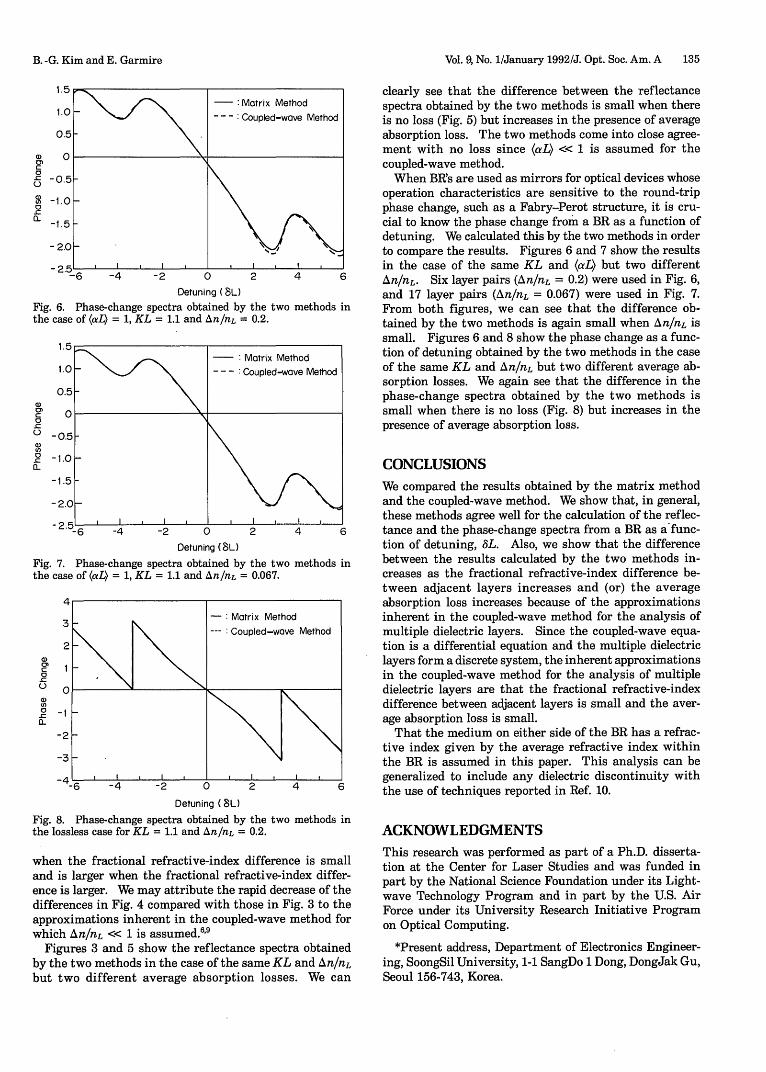
Fig. 6. Phase-change spectra obtained by the two methods inthe case of (aL) = 1, KL = 1.1 and An/nL = 0.2.
1.
1.
0.a,CC0~cU0)
a).CIL
-0.-1 .(
- 1
-2.
-2.
Fig. 7.the cas
c 1a,
.CC0
0 -.r_a-
-2
clearly see that the difference between the reflectancespectra obtained by the two methods is small when thereis no loss (Fig. 5) but increases in the presence of averageabsorption loss. The two methods come into close agree-ment with no loss since (aL) << 1 is assumed for thecoupled-wave method.
When BR's are used as mirrors for optical devices whoseoperation characteristics are sensitive to the round-tripphase change, such as a Fabry-Perot structure, it is cru-cial to know the phase change from a BR as a function ofdetuning. We calculated this by the two methods in orderto compare the results. Figures 6 and 7 show the resultsin the case of the same KL and (aL) but two differentAn/nL. Six layer pairs (An/nL = 0.2) were used in Fig. 6,and 17 layer pairs (An/nL = 0.067) were used in Fig. 7.From both figures, we can see that the difference ob-tained by the two methods is again small when An/nL issmall. Figures 6 and 8 show the phase change as a func-tion of detuning obtained by the two methods in the caseof the same KL and An/nL but two different average ab-sorption losses. We again see that the difference in thephase-change spectra obtained by the two methods issmall when there is no loss (Fig. 8) but increases in thepresence of average absorption loss.
CONCLUSIONS
5- \ t \We compared the results obtained by the matrix methodoH and the coupled-wave method. We show that, in general,
I , | C { I , | , , , these methods agree well for the calculation of the reflec--6 -4 -2 0 2 4 6 tance and the phase-change spectra from a BR as a func-
Detuning (8L) tion of detuning, AL. Also, we show that the differencePhase-change spectra obtained by the two methods in between the results calculated by the two methods in-
3e of (aL) = 1, KL = 1.1 and An/nL = 0.067. creases as the fractional refractive-index difference be-tween adjacent layers increases and (or) the averageabsorption loss increases because of the approximations
- Matrix Method inherent in the coupled-wave method for the analysis ofCoupled-wave Method multiple dielectric layers. Since the coupled-wave equa-
tion is a differential equation and the multiple dielectriclayers form a discrete system, the inherent approximationsin the coupled-wave method for the analysis of multipledielectric layers are that the fractional refractive-indexdifference between adjacent layers is small and the aver-age absorption loss is small.
That the medium on either side of the BR has a refrac-tive index given by the average refractive index withinthe BR is assumed in this paper. This analysis can bez 6 4 -( , l , , ,generalized to include any dielectric discontinuity with-2 -4 0 2 4 6 the use of techniques reported in Ref. 10.
Detuning (L)
Fig. 8. Phase-change spectra obtained by the two methods inthe lossless case for KL = 1.1 and An/nL = 0.2.
when the fractional refractive-index difference is smalland is larger when the fractional refractive-index differ-ence is larger. We may attribute the rapid decrease of thedifferences in Fig. 4 compared with those in Fig. 3 to theapproximations inherent in the coupled-wave method forwhich An/nL << 1 is assumed. 6 9
Figures 3 and 5 show the reflectance spectra obtainedby the two methods in the case of the same KL and A n/nLbut two different average absorption losses. We can
ACKNOWLEDGMENTSThis research was performed as part of a Ph.D. disserta-tion at the Center for Laser Studies and was funded inpart by the National Science Foundation under its Light-wave Technology Program and in part by the U.S. AirForce under its University Research Initiative Programon Optical Computing.
*Present address, Department of Electronics Engineer-ing, SoongSil University, 1-1 SangDo 1 Dong, DongJak Gu,Seoul 156-743, Korea.
- Matrix Method0 - -- : Coupled-wave Method
5
n1 IN
5I
)
B. -G. Kim and E. Garmire
1J
136 J. Opt. Soc. Am. A/Vol. 9, No. 1/January 1992
REFERENCES
1. P. L. Gourley and T. J. Drummond, "Single crystal, epitaxialmultilayrs of AlAs, GaAs, and Al. Gal -,As for use as opticalinterferometric elements," Appl. Phys. Lett. 49, 489-491(1986).
2. M. Ogura, T. Hata, and T. Yao, "Distributed feedback surfaceemitting laser diode with multilayered heterostructure," Jpn.J. Appl. Phys. 23, L512-L514 (1984).
3. J. L. Jewell, A. Scherer, S. L. McCall, A. C. Gossard, and J. H.English, "GaAs-AlAs monolithic microresonator arrays,"Appl. Phys. Lett. 51, 94-96 (1987).
4. B. G. Kim, E. Garmire, S. G. Hummel, and P. D. Dapkus,"Nonlinear Bragg reflector based on saturable absorption,"Appl. Phys. Lett. 54, 1095-1097 (1989).
B. -G. Kim and E. Garmire
5. M. Born and E. Wolf, Principles of Optics (Macmillan,New York, 1964).
6. A. Yariv and P. Yeh, Optical Waves in Crystals (Wiley,New York, 1984).
7. A. K. Ghatak, K. Thyagarajan, and M. R. Shenoy, "Numericalanalysis of planar optical waveguides using matrix ap-proach," IEEE J. Lightwave Technol. LT-5, 660-667 (1987).
8. W Streifer, D. R. Scifres, and R. D. Burnham, 'Analysis ofgrating-coupled radiation in GaAs: GaAlAs lasers and wave-guides," IEEE J. Quantum Electron. QE-12, 422-428 (1976).
9. H. A. Haus, Waves and Fields in Optoelectronics (Prentice-Hall, Englewood Cliffs, N.J., 1984).
10. B. G. Kim and E. Garmire, "The effect of front facet reflec-tions on the reflectivity of Bragg reflectors," Opt. Lett. 16,1065-1067 (1991).