COMPARISON BETWEEN THE MEASURED PASSING DISCHARGES THROUGH LONG THROATED FLUME AND ESTIMATED
DISCHARGE BY WINFLUME SOFTWARE
Samad Emamgholizadeh1, Ehsan Kazemassar2 and Omid Masodi3
1Department of Water and Soil, Agriculture College, Shahrood University, Shahrood, Iran 2Department of Water, Azad University of Dezful, Iran
3Department of Civil Engineering, Engineering College, Azad University of Shahrood, Iran E-Mail: [email protected]
ABSTRACT
In the flow measuring structures with control section such as Long-throated flumes and broad-crested weirs, a relationship would be produced between water depth and discharge. The long-throated flume is the new structure which proposed for flow measuring. This structure provides economical and flexible water measurement capabilities for a wide variety of open-channel flow situations. The advantages of this structure include minimal head loss, low construction cost, adaptability to a variety of channel types, and ability to measure wide ranges of flows with custom-designed structures. In order to investigate the ability of Winflume model in estimating discharge passing through long throated flume, a series of laboratory experiments were carried out in a flow measurement flume of rectangular cross section. The experiments carried out with three upstream slope (1:1, 1:2 and 1:3) and three downstream slope (vertical, 1:6 and 1:10), two step height (P = 7.62 and 15.62cm), constant throat width (w = 25cm) and throat length (L = 30.48cm). Eleven different models made of Plexiglas were tested in a horizontal flume for large range of discharges. The results achieved shows that the model has good ability to simulate the flow and to estimate discharge passing through long-throated flume. The average error in the estimation of discharge was 10 percent. Keywords: water measurement, long throated flume, winflume, physical model. 1. INTRODUCTION
Efficient water management in an irrigation system requires an accurate water measurement at different locations (Raza, 2007). Accurate water measurement is essential to maintaining equity of water delivery within an irrigation company or water districts. Good management of our scarce water resource is dependent upon quantifying supplies and uses with accurate measurement techniques. State water rights adjudication and management procedures often require installation of water measurement devices and keeping records of flows.
For the discharge measurement in canals various devices can be used for example, it can be current meter, overflow, flumes and etc. Flumes can be categorized in two groups:
Short-throated Flume long-throated Flume
For short-throated Flume it can point out to the Parshall flume, Cutthroat flume, H flume. Parshall flumes and other types of flumes have advantages of lower head loss and of passing the sediment on through but are more costly to fabricate and install. Non-level flumes and improper installation (insufficient crest height) are the most common problems. Cutthroat flumes (developed at USU) are simpler to construct than Parshall flumes and can operate as free flow conditions at a higher degree of submergence. The long-throated ramp flume (also known as a broad-crested-weir) has strong advantages in flat
ditches or canals as free flow conditions can be maintained at 90% submergence and above. 1.1. Long-throated measurement flumes
The terms ‘‘long-throated flume’’ and ‘broad-crested weir’’ encompass a large family of structures used to measure discharge in open channels. Other names commonly used to describe these structures are ramp flume or weir, and Replogle flume or weir (Wahl et al., 2005). A variety of specific configurations are possible depending on the type of approach channel, the shape of the throat section, the location of the gauging station, and the use or lack of a diverging transition section(Wahl et al., 2000). Long-throated flumes are coming into general use because they can be easily fitted into complex channel shapes as well as simple shapes (Replogle, 1975; Bos et al., 1991). The cross-sectional flexibility of long-throated flumes allows them to fit various channel shapes more conveniently than short-throated flumes, which have fixed sizes and shapes. Because of the ability to match the channel shape, the construction of forms is usually simplified. In contrast, the fixed geometry of short-throated (including Parshall) flumes usually makes upstream and downstream transitions necessary and may require long wing walls. Because of their flexibility and capability to fit any channel shape, long-throated flumes have more gradual transitions. Thus, floating debris presents fewer problems. Also, field observations have shown that the structure can be designed to pass sediment transported by channels with sub critical flow. Long-throated flumes have many advantages compared to other
measuring devices, including Parshall flumes. Long-throated flumes are more accurate, cost less, have better technical performance, and can be computer designed and calibrated. Thus, long-throated flumes are preferred over Parshall flumes for new installations (USBR Water measurement manual, 2001).).
The hydraulic theory for predicting discharge through long-throated flumes has resulted from over a century of development. The first laboratory and theoretical studies on critical-depth flumes were made by Belanger in 1849 and by Bazin in 1896 (ref. Clemmens et al., 2001). Theoretical predictions of flow were investigated by Ackers and Harrison (1963) and further by Replogle (1975) (ref. Clemmens et al., 2001). Bos et al., (1984) described the theory for determining discharge through these flumes.
A simple type of long-throated flume developed and described by Replogle et al. (1991) consists of a flat raised sill or crest across a trapezoidal channel with an approach ramp transition from the approach channel invert. The crest drops vertically at the downstream end back to the downstream canal invert. 1.2. The Win flume computer program
WinFlume is the latest in a series of long-throated flume design tools originally developed through the cooperative research efforts of the Agricultural Research Service (ARS) and the International Institute for Land Reclamation and Improvement (ILRI). Albert J. Clemmens and John A. Replogle of ARS and Marinus G. Bos of ILRI developed many of the original hydraulic design criteria and computation procedures. This newest version of the software was developed through the cooperative efforts of the U.S. Bureau of Reclamation's Water Resources Research Laboratory and ARS’s U.S. Water Conservation Laboratory, with funding from Reclamation’s Water Conservation-Field Services (WinFlume User’s Manual, 2001). Operation of the WinFlume program is based on an editable graphic display of flume dimensions, auxiliary screens used to enter flume and canal properties and design requirements, and several screens devoted to analysis, review, and output of flume designs. Seven different cross-section shapes are available for the approach and tail water sections of a flume and 14 control-section shapes are available, including circular, parabolic, trapezoidal, and complex shapes (Wahl et al., 2000). In addition to the flume and canal geometry, the user must define hydraulic properties of the structure and the site, and design requirements to be used for later evaluation and review of flume designs. Specific information needs include (Wahl et al., 2000):
The hydraulic roughness of the material used for construction of the flume.
Range of flows to be measured and the associated tail water levels at the site.
Allowable flow measurement uncertainty at minimum and maximum discharge.
Required freeboard in the approach channel at maximum flow.
The WinFlume program serves two primary purposes (WinFlume User’s manual, 2001). 1.2.1 Calibration of existing flow measurement
structures fitting the criteria for analysis as long-throated flumes
WinFlume can generate rating tables, Q vs. h1 charts, curve-fit equations for use in data loggers, and wall gage data and plots. WinFlume can also compare field-measured Q vs. h1 data to the theoretical rating curve of a structure.
WinFlume can be used as a design review tool to identify design deficiencies in existing structures. 1.2.2 Design of new structures
WinFlume can be used to design new flow measurement structures for new and existing canal systems. Designs can be developed manually by the user and analyzed using WinFlume to ensure proper operation, or WinFlume’s design module can be used to develop designs that have desired head loss characteristics and meet other performance requirements. 2. MATERIALS AND METHODS 2.1. Experimental setup
In order to achieve the objective of this study a physical model is considered. Thus all series of experiments were conducted in a glass-walled horizontal flume 12.0m long, 0.25m wide and 0.50m deep in the Hydraulic Laboratory at the Water and Science Collage of Shahid Chamran University, Ahwaz, Iran. Figure-1 shows the plan view of the hydraulic laboratory and the flume which used in this research. Long-throated flumes were manufactured from glass and placed at the distance of 2m from the upstream of the main flume system (the test section in Figure-2). In order to dissipating of the inflow energy, first flow passed through flow dissipater area, then traveled about 2 m to the test section. For each test, the upstream step-referenced head on the flume was measured using a point gage (estimated measurement uncertainty ± 0.1 mm), and the discharge through the flume was determined using the triangular weir (53 degree). The tail water levels relative to the step elevation were also recorded.
For carry out of experiments 11 kind of flumes were used. Table-1 summarizes the dimensions of the tested flumes. The tested flumes shared several characteristics. All utilized rectangular-shaped approach, throat, and tail water sections. The throat width (w) and the length of the throat section (L) were held constant at 25cm and 30.48cm, respectively for all flumes. The principal differences between the different tested flumes were the step height, upstream and downstream slope. The upstream slope was 1:1, 2:1 and 3:1. The downstream slope was 6:1, 10:1 and vertical. Also the step height was
The measured parameters during tests In order to collect the needed data during the tests
the following measurements were done:
- The water depth of flow at the upstream of the model - The initial depth of hydraulic jump - The second depth of hydraulic jump
- The water depth of flow at the downstream of the model
- The water depth of flow at the upstream of the overflow triangle 53 degrees
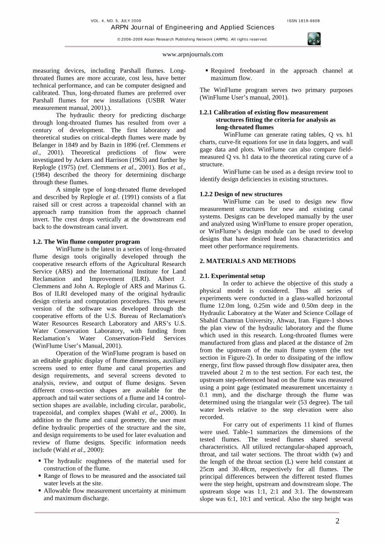
Figure-2 shows the long-throated flume during the test. In this experiment the width of long throated was 25cm, and also the upstream and downstream and sill height were 2:1, 0:1 and 7.62cm.
Figure-2. Upstream and longitudinal view looking at flume c, operating at a flow rate of 10 lit/s.
3. RESULTS AND DISCUSSIONS
All of the measured quantities from the experiments conducted in the course of this study were given by Asare (2006). With using of the achieved results with 11 kinds of models, in the following sections results of experiments were analyzed and summarized.
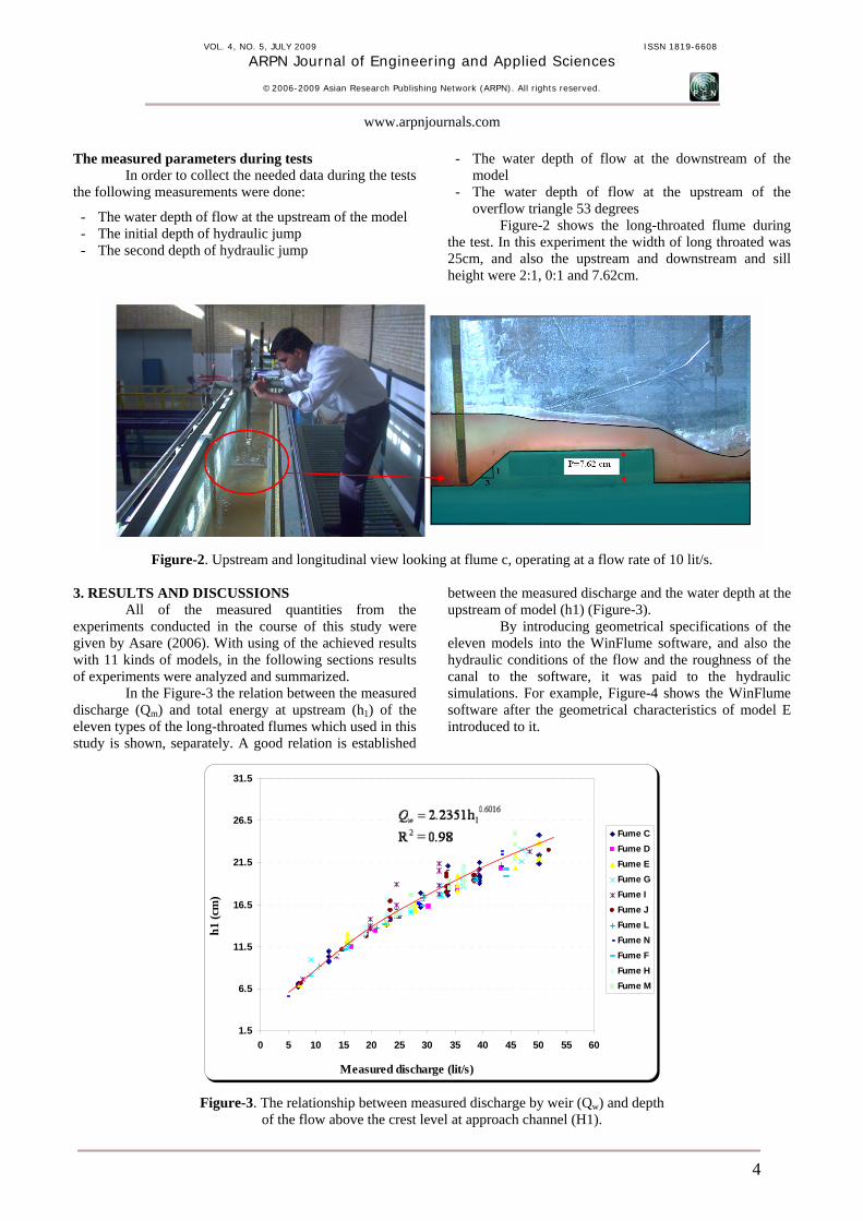
In the Figure-3 the relation between the measured discharge (Qm) and total energy at upstream (h1) of the eleven types of the long-throated flumes which used in this study is shown, separately. A good relation is established
between the measured discharge and the water depth at the upstream of model (h1) (Figure-3).
By introducing geometrical specifications of the eleven models into the WinFlume software, and also the hydraulic conditions of the flow and the roughness of the canal to the software, it was paid to the hydraulic simulations. For example, Figure-4 shows the WinFlume software after the geometrical characteristics of model E introduced to it.
Figure-4. WinFlume’s main screen shows the flume and canal geometry. The output of the model can be different cases which it can be used according to the needs. For example, the output of the model can be parameters relation between the discharge and the following parameters:
Upstream Froude number (Fr) The energy loss (H2-H1) The ratio of upstream energy head to control section length exceeds (H1/L)
The upstream energy head (H1)
The discharge coefficient(Cd) The coefficient of the discharge velocity (Cv) Submergence ration (H2/H1) Modular Limit
For example, in Figure-5 the relation between discharge, upstream head (h1) and coefficient of discharge (Cd) which the geometry of the flume G was introduced to it, is shown.
Flume G - Revision 22
Water level atgage, h1
Dischargecoefficient
Head, cm DischargeCoefficient
Discharge, liters/s
0
5
10
15
20
25
0.95
0.96
0.97
0.98
0.99
1.00
0 10 20 30 40 50 60
Flume G - Revision 22
Water level atgage, h1
Dischargecoefficient
Head, cm DischargeCoefficient
Discharge, liters/s
0
5
10
15
20
25
0.95
0.96
0.97
0.98
0.99
1.00
0 10 20 30 40 50 60
Figure-5. The relation between discharge, upstream head (h1) and coefficient of discharge (Cd) for flume G.
In order to investigate the capability of the model to estimate the passing discharge through the flume, the results of the measured discharge in the experimental condition was compared with the calculated discharge by model. Table-2 shows the error between the measured and
estimated discharge for eleven types of flumes. Also in the Figure-6, the relation between the measured and calculated discharge and also the error of the estimation of discharge is shown.
Table-2. The error between the measured and estimated discharge for eleven types of flumes.
Flume Type Fume C
Fume D
Fume E
Fume G
Fume I
Fume J
Fume L
Fume N
Fume F
Fume H
Fume M
Number of experiments 27 7 8 16 18 19 10 16 12 14 16
Figure-6. The predicted discharge error that the WinFlume model produced.
With respect to the Figure-6, the plotted error against discharge show that an increasing of passing discharge through flume, the predicted discharge error will decrease. Also discharge’s amount estimated by WinFlume model in all got more than the actual amount. This result similarly reported by Wahl et al., 2000. This is consistent with the hypothesis that critical depth is not occurring in the throat section, since, by definition, when critical depth occurs we obtain the theoretically maximum possible flow rate for a given upstream head (Wahl et al., 2000). Also, the comparison of the measured discharge and predicted by the model show that in the case where the upstream and downstream slope was equal, when the step height increased from 7.62 cm to 15.24 cm, the differences between the measured and predicted discharge is reduced.
In other word, the increasing of step height would caused the critical discharge is performed completely in the throat of the flume. In total, the investigation of the
error between the measured and calculated discharge shows that, the average error of the estimated discharge by the WinFlume model was 10.6 percent. So the model has good ability for estimation of the passing discharge through the long throated flume, therefore it can be used successfully to simulations hydraulic process of passing discharge through the long throated flume. 4. CONCLUSIONS
Long-throated flumes are a well-developed technology that provides economical and flexible water measurement capabilities for a wide variety of open-channel flow situations. The structures have low head loss requirements among other advantages, and can be calibrated using a state-of-the-art computer program available to the public on the Internet (Wahl et al., 2000).
With regard to the laboratory results and the results of the simulations using the model take Win Flume,
the comparison in the present research show that the Win Flume model has good ability (average error 10.6 percent) to estimation of passing discharge through long throated flume. The results of other researchers like Wahl et al., 2000 shows that the maximum and minimum error between measured and calculated discharge was 5 and 25 percent and average error was 13 percent. So the results of this research shows that the Win Flume can simulations hydraulic process of passing discharge through long throated flume, and it can be used for calibration the flume. 5. ACKNOWLEDGEMENTS
This research study was supported by Shahrood University of Technology, Iran. The first author wants to thank for the support during all stages of work. REFERENCES Assare K. 2006. Investigation of the Hydraulic Characteristics of the Long-Throat Flumes (In Persian). Ms Thesis, Shahid Chamran Univ., Ahwaz, Iran. p. 182. Bos MG, Replogle JA, Clemmens AJ. 1991. Flow Measuring Flumes for Open Channel Systems. American Society of Agricultural Engineers. Bos M.G., J.A. Replogle and A.J. Clemmens. 1984. Flow Measuring Flumes for Open Channel Systems, John Wiley and Sons, New York, NY. Clemmens Albert J., Tony L. Wahl, Marinus G. Bos, and John A. Replogle. 2001. Water Measurement with Flumes
and Weirs, ILRI Publication 58, International Institute for Land Reclamation and Improvement, Wageningen, the Netherlands. p. 382. Raza A, Latif, M and Nabi G. 2007. Fabrication and evaluation of a portable long-throated flume. Irrig. and Drain. 56: 565-575. Replogle JA. 1975. Critical Flow Flumes with Complex Cross Sections. Proceedings of the Specialty Conference on Irrigation and Drainage in an Age of Competition for Resources. ASCE, Logan, Utah. 366-388. Wahl Tony L., Albert J. Clemmens, John A. Replogle, and Marinus G. Bos. 2000. WinFlume-Windows-Based Software for the Design of Long-Throated Measuring Flumes. Fourth Decennial National Irrigation Symposium, American Society of Agricultural Engineers. Wahl TL, Clemmens AJ, Replogle JA, Bos MG. 2005. Simplified design of flumes and weirs. Irrigation and Drainage. 54: 231-247. Water Measurement Manual, Chapter 8. 2001. U.S. Bureau of Reclamation. Revised reprint 2001, U.S. Government. Printing Office, Washington, DC. 20402. p. 63. WinFlume User’s Manual. 2001. Software for Design and Calibration of Long-Throated Flumes and Broad-Crested Weirs for Open-Channel Water Flow Measurement. p. 50.