UW - Madison Computational Mechanics Center 2007 EUVL Symposium Slide 1 Comparison of Comparison of Coulombic Coulombic and and Johnsen Johnsen - - Rahbek Rahbek Electrostatic Electrostatic Chucking for EUV Lithography Chucking for EUV Lithography M. R. Sogard Nikon Research Corporation of America, Belmont, CA A.R. Mikkelson, V. Ramaswamy, M. Nataraju, K.T. Turner and R.L. Engelstad University of Wisconsin, Madison, WI Acknowledgments Research funded by Nikon, SEMATECH, Intel, and SRC. Computer support provided by Intel and Microsoft.
Transcript
UW - MadisonComputational Mechanics Center
2007 EUVL Symposium
Slide 1
Comparison of Comparison of CoulombicCoulombic and and JohnsenJohnsen--RahbekRahbek Electrostatic Electrostatic Chucking for EUV LithographyChucking for EUV Lithography
M. R. SogardNikon Research Corporation of America, Belmont, CA
A.R. Mikkelson, V. Ramaswamy, M. Nataraju, K.T. Turner and R.L. Engelstad
University of Wisconsin, Madison, WI
AcknowledgmentsResearch funded by Nikon, SEMATECH, Intel, and SRC.
Computer support provided by Intel and Microsoft.
UW - MadisonComputational Mechanics Center
2007 EUVL Symposium
Slide 2
Presentation Outline• Motivation and objectives• Characteristics of electrostatic chucking• Finite element (FE) model description and
simulation results• Chuck comparisons and conclusions
• Clamping performance• Effects of reticle non-flatness• Effects of particle entrapment
UW - MadisonComputational Mechanics Center
2007 EUVL Symposium
Slide 3
EUVL Flatness Requirements SEMI Standard P37 and P40
• The flatness of the EUVL mask is a key issue to minimize image placement errors due to non-telecentric illumination.
• Achieving this level of flatness requires the use of an electrostatic chuck to hold the reticle.
Specifications in the EUVL Mask Standard (SEMI P37):
Frontside and Backside in Quality Area (QA):~ 30 - 100 nm p-v flatness
152 mm152 mm
Low Order Thickness Variation (LOTV) in QA:~ 30 - 100 nm p-v flatnessQuality Area = 142 mm × 142 mm
Specifications in the EUVL Mask Chucking Standard (SEMI P40):-- stiffness ≥ 30 kN-m-- flatness ≈ 50 nm (p-v)
UW - MadisonComputational Mechanics Center
2007 EUVL Symposium
Slide 4
Electrostatic ChuckingTypes of Chucks
Coulomb Johnsen-Rahbek
• Type of chuck is characterized by the dielectric material and the resulting mechanism of force generation.
• Chucks can be either monopolar or bipolar.
• Slab-type or pin-type based on the surface characteristics. A pin-type chuck is proposed to minimize the effects of particles.
P = electrostatic pressureF = electrostatic forceA = area of the electrodeVo = applied voltageεo = permittivity of free space (or air gap)K = relative permittivity of the dielectric materialtD = the dielectric film thicknessδ = total gap between the backside of the mask and the dielectric surface
2
22
)(8 δε
KtKV
AFP
D
oo
+==
Bipolar Chuck
UW - MadisonComputational Mechanics Center
2007 EUVL Symposium
Slide 6
Johnsen-Rahbek (J-R) ChuckSchematic and Working Principle
RV = volume resistance of the dielectricRCL = effective resistance of contact
layer
• The dielectric has a finite resistance.
• Current flowing through the dielectric and the substrate creates a charge layer at the dielectric-substrate interface (contact layer thickness tCL), yielding a strong attractive force.
tCL is related to surface roughness
Chuck
Reticle
+
-
RV
Vo tCL
RCL
++
++
++ +
charge accumulation
-- -- ---
-- -+++ ++ +
- - ---
UW - MadisonComputational Mechanics Center
2007 EUVL Symposium
Slide 7
Johnsen-Rahbek ChuckPhenomenological Model
Coulomb term J-R term
( )( )
( ){ } ⎥⎥
⎦
⎤
⎢⎢
⎣
⎡
⎟⎟⎠
⎞⎜⎜⎝
⎛
++⎟
⎟⎠
⎞⎜⎜⎝
⎛
++=
222
00
12 VCLCL
VCL
CLD RRt
RR
tKtKV
P αδ
ε
εo: permittivity of free spaceK: relative dielectric constantRCL: resistance of the contact layerRV : volume resistance of the dielectric materialδ : physical gap between reticle and dielectricα : empirical factor of the nonuniform charge distribution on the interface
In practice, RCL and RV can be measured; tCL is then obtained from a measurement of pressure at a given voltage.
Often the Coulomb term is negligible, because tD >> tCL in many cases.
UW - MadisonComputational Mechanics Center
2007 EUVL Symposium
Slide 8
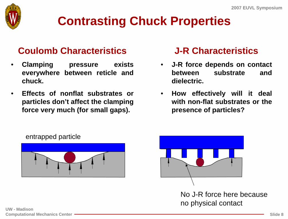
Contrasting Chuck Properties
Coulomb Characteristics• Clamping pressure exists
everywhere between reticle and chuck.
• Effects of nonflat substrates or particles don’t affect the clamping force very much (for small gaps).
J-R Characteristics• J-R force depends on contact
between substrate and dielectric.
• How effectively will it deal with non-flat substrates or the presence of particles?
entrapped particle
No J-R force here because no physical contact
UW - MadisonComputational Mechanics Center
2007 EUVL Symposium
Slide 9
Nonuniform Distribution of Charge
• The empirical factor α represents the effect of the nonuniform distribution of charge on the interface surfaces.
• A relationship for α as a function of gap has been assumed for modeling purposes and was initially introduced to help with FE model convergence.
0.0
0.5
1.0
1.5
2.0
2.5
3.0
0 10 20 30 40 50
α
Gap (nm)
αmax = 2.5
Gapα=0 = 30 nm
• However, short range forces exist over a comparable distance:
– van der Waals (∝ 1 / gap3)
– Casimir (∝ 1 / gap4)
• So this gap dependence is physically reasonable.
UW - MadisonComputational Mechanics Center
2007 EUVL Symposium
Slide 10
FE Simulation of Electrostatic Chucking• Full 3-D FE models developed for both Coulomb and J-R chucks.
• Nonflatness measurements of the frontside and backside surfaces of the reticle, as well as the top surface of the chuck, are used as input.
• The non-flatness values are consistent with SEMI P37, P40
• Models include:-- gap-dependent pressures -- contact friction (µ = 0.2)-- stiffness of the chuck
• FE simulations predict:-- final flatness of reticle patterned surface-- final flatness of reticle backside surface-- final bow of the chuck -- final gap between the reticle and chuck
Chuck
Gravity neglected.
Chuck
UW - MadisonComputational Mechanics Center
2007 EUVL Symposium
Slide 11
FE Electrostatic Chucking ModelsChuck and Reticle
XY
Z
Reticle
Chuck
Chuck with Pin Array(with no reticle)
UW - MadisonComputational Mechanics Center
2007 EUVL Symposium
Slide 12
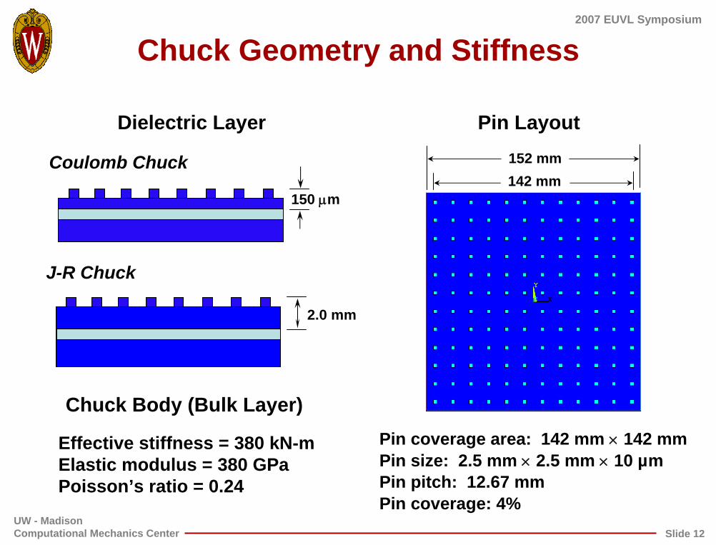
Chuck Geometry and Stiffness
Dielectric Layer Pin Layout
142 mm152 mmCoulomb Chuck
X
Y
Z X
Y
Z X
Y
Z X
Y
Z X
Y
Z
150 µm
J-R Chuck
2.0 mm
Chuck Body (Bulk Layer)Pin coverage area: 142 mm × 142 mmPin size: 2.5 mm × 2.5 mm × 10 µmPin pitch: 12.67 mmPin coverage: 4%
Nonflatness of Electrostatic Chuck• Nonflatness of a Coulomb chuck was measured
interferometrically.
• Measured chuck data scaled to meet the flatness specified in theEUVL chucking standard.
Interferometric measurement of the chuck surface is represented by Legendre polynomials and used as input into the FE models.
Interferometric Measurement of Chuck Surface
p-v = 45.3 nm
nm
Coulomb Pin Chuck Mathematical Fit
UW - MadisonComputational Mechanics Center
2007 EUVL Symposium
Slide 14
Polished Nonflatness of ReticleExample Case
Thickness VariationBackside (BS)
p-v = 50 nm
• Thickness variation was calculated by subtracting the backside flatness data from the frontsideflatness data.
Max = 100 nm
Interferometric measurements represented by Legendre polynomials are used as input into the FE models.
Frontside (FS)
p-v = 50 nm
UW - MadisonComputational Mechanics Center
2007 EUVL Symposium
Slide 15
Simulating Reticle Multi-layer Thin Film Deposition
• After generating the FE model of the EUV substrate with the FS and BS nonflatness, the deposition of the ideal (uniform stress and thickness) layers is simulated.
• For the Example Case, the out-of-plane distortion (OPD) of the FS is 1000 nm p-v. The shape is convex due to the net compressive stress.
FE Model illustrating OPD contours.
OPD Frontside (p-v = 1000 nm)
UW - MadisonComputational Mechanics Center
2007 EUVL Symposium
Slide 16
Pressure as a Function of GapAve. Pressure of 3 kPa
Effects of Particle Entrapment: Coulomb Effects of Particle Entrapment: Coulomb vs. vs. JohnsenJohnsen--RahbekRahbek Electrostatic ChucksElectrostatic Chucks
Coulomb Chuck J-R Chuck
entrapped particle
Force generated everywhere
No J-R force here because no physical contact
• Do entrapped particles have similar effects on both types of chuck?
UW - MadisonComputational Mechanics Center
2007 EUVL Symposium
Slide 25
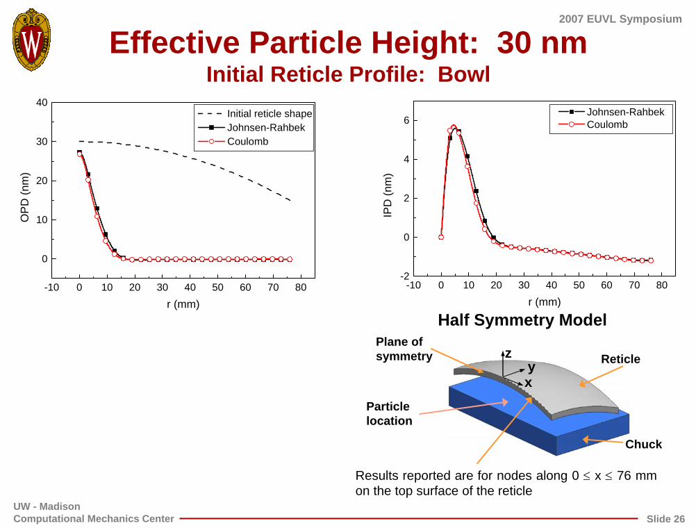
Particle Macro-Scale Model Details
Effective particle height, h
ReticleChuck
P
Cutaway view of reticle clamped to a rigid chuck
Original particle sizer Gap radius
• Reticle is assumed to be of ULE® material and initially bowl shaped
• Chuck is perfectly flat and rigid
• Effective particle height (h) is the residual height of the deformed particle (neglecting local deformation of the chuck and reticle surfaces). Pressure loading (P) is gap dependent with a maximum pressure of 15 kPa occurring at zero gap. Note: in this model the effective particle height says nothing about the original particle size.
• r is the radial coordinate from the location of the particle
• The larger separation gap means the J-R chuck doesn’t clamp as strongly.
•But the IPD is significantly smaller than for the Coulomb chuck.
UW - MadisonComputational Mechanics Center
2007 EUVL Symposium
Slide 30
Conclusions
• The J-R chuck is not as effective in “flattening” trapped particles as the Coulomb chuck for large effective heights, but the associated IPD is smaller.
• However for effective particle heights comparable to the SEMI non-flatness specs (< 100 nm), there is little difference between the two types of chuck.
• Effective particle height can be significantly less than real particle size.
• The quantitative effects of particle and chuck/substrate deformation are being investigated.
UW - MadisonComputational Mechanics Center
2007 EUVL Symposium
Slide 31
Chuck Comparison
Coulomb Johnsen-Rahbek
Forceforce
insensitive to gap, spatially
uniform
some distortion of reticle between
pins
no distortion of reticle between
pins
force highly dependent on gap,
not spatially uniform
Heatgeneration
some ohmicheating due to
leakage current; not serious
problem
Advantages Disadvantages Advantages Disadvantages
Lithography industry experience
Applied voltage
Tolerance to particles
considerable limited
limited clamping force - requires
high voltage
higher force per volt in
contact areas
force not dependent on
particle presence
needs tall pins to tolerate particles –this reduces force
pin height is irrelevant –
more particle tolerant
less able to handle particles on pins
UW - MadisonComputational Mechanics Center
2007 EUVL Symposium
Slide 32
Summary and Conclusions• The successful implementation of EUV lithography requires the use
of an electrostatic chuck to support and flatten the mask duringscanning exposure.
• A phenomenological model describing the force-gap relationship for a J-R chuck is presented and compared to the Coulomb response.
• Full 3-D FE structural models have been developed to compare the clamping performance of the two types of chucks. The relative advantages and disadvantages of both have been identified.
• The effects of entrapped particles on the clamping performance of the two kinds of chuck have been examined in a global model.
• FE simulation results are currently being used to establish specifications for chuck geometry and to identify the range of flatness variations that can be accommodated with electrostatic chucking.