Comparison of Physical and Software- Implemented Fault Injection Techniques Jean Arlat, Member, IEEE, Yves Crouzet, Johan Karlsson, Member, IEEE, Peter Folkesson, Member, IEEE, Emmerich Fuchs, Member, IEEE Computer Society, and Gu ¨nther H. Leber, Member, IEEE Abstract—This paper addresses the issue of characterizing the respective impact of fault injection techniques. Three physical techniques and one software-implemented technique that have been used to assess the fault tolerance features of the MARS fault- tolerant distributed real-time system are compared and analyzed. After a short summary of the fault tolerance features of the MARS architecture and especially of the error detection mechanisms that were used to compare the erroneous behaviors induced by the fault injection techniques considered, we describe the common distributed testbed and test scenario implemented to perform a coherent set of fault injection campaigns. The main features of the four fault injection techniques considered are then briefly described and the results obtained are finally presented and discussed. Emphasis is put on the analysis of the specific impact and merit of each injection technique. Index Terms—Fault injection techniques, experimental assessment, fault-tolerant computing, error detection coverage. æ 1 INTRODUCTION T HE dependability assessment of a fault-tolerant compu- ter system is a complex task that requires the use of different levels of evaluation approaches and related tools. In complement to other possible approaches such as proving or analytical modeling whose applicability and accuracy are significantly restricted in the case of complex systems, fault injection has long been recognized to be particularly attractive and useful. Indeed, by speeding up the occurrence of errors and failures, fault injection is, in fact, a method for testing the fault tolerance mechanisms with respect to a specific set of inputs they are meant to cope with: the faults. Fault injection can be applied either on a simulation model of the target fault- tolerant system or on a hardware-and-software implementa- tion (e.g., see [1], [2], [3], [4]). Clearly, simulation-based fault injection is desirable as it can provide early checks in the design process of fault tolerance mechanisms (e.g., see [5]). Nevertheless, it is worth noting that fault injection on a prototype featuring the actual interactions between the hardware and software dimensions of the fault tolerance mechanisms supplies a more realistic and necessary complement to validate their implementation in a fault-tolerant system. Initially, most studies related to the application of fault injection on a prototype of a fault-tolerant system relied on physical fault injection (FI, for short), i.e., the introduction of faults through the hardware layer of the target system (e.g., see [6]). A trend favoring the injection of errors through the software layer for simulating physical faults (i.e., software-implemented fault injection—SWIFI for short) has emerged (e.g., see [7], [8], [9], [10], [11]). Such an approach facilitates the application of fault injection by overcoming several problems associated with FI techni- ques (such as controllability, repeatability, etc.). Moreover, recent studies have shown that SWIFI was also able to emulate some types of software faults (e.g., see [12]). Nevertheless, in spite of the difficulties in developing support environments and conducting experiments, FI techniques enable real faults to be injected in a very close representation of the target system especially without any alteration to the software being executed. The large body of works concerning FI used widely different techniques and/or were applied to distinct target systems. This significantly hampers the possibility to identify the diffi- culties/benefits associated with each fault injection techni- que and to analyze the results obtained. Thus, more experimental work is needed to better establish the relationship and differences between the fault injection techniques that are available to help the designers in assessing the dependability and fault tolerance properties of a computer system. In particular, one key concern that is often related to fault injection-based experiments is usually termed fault representativeness, i.e., the plausibility of the supported fault model with respect to actual faults. In this paper, we advocate that the study of the impact and consequences of an injected fault (i.e., the error propagated) offers a more pragmatic and sensible means to address the representativeness issue. Accordingly, we distinguish be- tween two categories of approaches, depending on whether the analysis concerns the erroneous behaviors provoked by IEEE TRANSACTIONS ON COMPUTERS, VOL. 52, NO. 9, SEPTEMBER 2003 1115 . J. Arlat and Y. Crouzet are with LAAS-CNRS, 7, Avenue du Colonel Roche, 31077 Toulouse Cedex 4, France. E-mail: {Jean.Arlat, Yves.Crouzet}@laas.fr. . J. Karlsson and P. Folkesson are with the Department of Computer Engineering, Chalmers University of Technology, SE-412 96 Goteborg, Sweden. E-mail: {johan, peterf}@ce.chalmers.se. . E. Fuchs was with the Vienna University of Technology. He is now with DECOMSYS-Dependable Computer Systems, Stumpergasse 48/14, A- 1060 Wien, Austria. E-mail: [email protected]. . G.H. Leber was with the Vienna University of Technology. He is now with Adcon Telemetry AG, Inkustraße 24, A-3400 Klosterneuburg, Austria. E-mail: [email protected]. Manuscript received 14 Feb. 2000; revised 12 Feb. 2002; accepted 24 Feb. 2003. For information on obtaining reprints of this article, please send e-mail to: [email protected], and reference IEEECS Log Number 111469. 0018-9340/03/$17.00 ß 2003 IEEE Published by the IEEE Computer Society
Transcript
Comparison of Physical and Software-Implemented Fault Injection Techniques
Jean Arlat, Member, IEEE, Yves Crouzet, Johan Karlsson, Member, IEEE,
Peter Folkesson, Member, IEEE, Emmerich Fuchs, Member, IEEE Computer Society, and
Gunther H. Leber, Member, IEEE
Abstract—This paper addresses the issue of characterizing the respective impact of fault injection techniques. Three physical
techniques and one software-implemented technique that have been used to assess the fault tolerance features of the MARS fault-
tolerant distributed real-time system are compared and analyzed. After a short summary of the fault tolerance features of the MARS
architecture and especially of the error detection mechanisms that were used to compare the erroneous behaviors induced by the fault
injection techniques considered, we describe the common distributed testbed and test scenario implemented to perform a coherent set
of fault injection campaigns. The main features of the four fault injection techniques considered are then briefly described and the
results obtained are finally presented and discussed. Emphasis is put on the analysis of the specific impact and merit of each injection
THE dependability assessment of a fault-tolerant compu-ter system is a complex task that requires the use of
different levels of evaluation approaches and related tools. Incomplement to other possible approaches such as proving oranalytical modeling whose applicability and accuracy aresignificantly restricted in the case of complex systems, faultinjectionhas long been recognized to be particularly attractiveand useful. Indeed, by speeding up the occurrence of errorsand failures, fault injection is, in fact, a method for testing thefault tolerance mechanisms with respect to a specific set ofinputs they are meant to cope with: the faults. Fault injectioncan be applied either on a simulation model of the target fault-tolerant system or on a hardware-and-software implementa-tion (e.g., see [1], [2], [3], [4]).
Clearly, simulation-based fault injection is desirable as itcan provide early checks in the design process of faulttolerance mechanisms (e.g., see [5]). Nevertheless, it isworth noting that fault injection on a prototype featuringthe actual interactions between the hardware and softwaredimensions of the fault tolerance mechanisms supplies amore realistic and necessary complement to validate theirimplementation in a fault-tolerant system.
Initially, most studies related to the application of faultinjection on a prototype of a fault-tolerant system relied onphysical fault injection (�FI, for short), i.e., the introductionof faults through the hardware layer of the target system(e.g., see [6]). A trend favoring the injection of errorsthrough the software layer for simulating physical faults(i.e., software-implemented fault injection—SWIFI forshort) has emerged (e.g., see [7], [8], [9], [10], [11]). Suchan approach facilitates the application of fault injection byovercoming several problems associated with �FI techni-ques (such as controllability, repeatability, etc.). Moreover,recent studies have shown that SWIFI was also able toemulate some types of software faults (e.g., see [12]).
Nevertheless, in spite of the difficulties in developingsupport environments and conducting experiments, �FItechniques enable real faults to be injected in a very closerepresentation of the target system especially without anyalteration to the software being executed. The large body ofworks concerning �FI used widely different techniquesand/or were applied to distinct target systems. Thissignificantly hampers the possibility to identify the diffi-culties/benefits associated with each fault injection techni-que and to analyze the results obtained.
Thus, more experimental work is needed to betterestablish the relationship and differences between the faultinjection techniques that are available to help the designersin assessing the dependability and fault tolerance propertiesof a computer system. In particular, one key concern that isoften related to fault injection-based experiments is usuallytermed fault representativeness, i.e., the plausibility of thesupported fault model with respect to actual faults. In thispaper, we advocate that the study of the impact andconsequences of an injected fault (i.e., the error propagated)offers a more pragmatic and sensible means to address therepresentativeness issue. Accordingly, we distinguish be-tween two categories of approaches, depending on whetherthe analysis concerns the erroneous behaviors provoked by
IEEE TRANSACTIONS ON COMPUTERS, VOL. 52, NO. 9, SEPTEMBER 2003 1115
. J. Arlat and Y. Crouzet are with LAAS-CNRS, 7, Avenue du ColonelRoche, 31077 Toulouse Cedex 4, France.E-mail: {Jean.Arlat, Yves.Crouzet}@laas.fr.
. J. Karlsson and P. Folkesson are with the Department of ComputerEngineering, Chalmers University of Technology, SE-412 96 Goteborg,Sweden. E-mail: {johan, peterf}@ce.chalmers.se.
. E. Fuchs was with the Vienna University of Technology. He is now withDECOMSYS-Dependable Computer Systems, Stumpergasse 48/14, A-1060 Wien, Austria. E-mail: [email protected].
. G.H. Leber was with the Vienna University of Technology. He is now withAdcon Telemetry AG, Inkustraße 24, A-3400 Klosterneuburg, Austria.E-mail: [email protected].
Manuscript received 14 Feb. 2000; revised 12 Feb. 2002; accepted 24 Feb.2003.For information on obtaining reprints of this article, please send e-mail to:[email protected], and reference IEEECS Log Number 111469.
0018-9340/03/$17.00 � 2003 IEEE Published by the IEEE Computer Society
1) some specific fault injection technique with respect to aset of real faults or 2) the application of several faultinjection techniques (most of the time in previous studiesonly two techniques were considered).
Clearly, in principle, the first approach is more desirableand convincing for assessing the accuracy of the behaviorsinduced by the fault injection techniques. However, it is notalways easy to gather a large amount of objective data onbehaviors caused by real faults to support such an analysis.Typical examples of related studies include the comparisonof the impact of real faults with respect to 1) extensive dataand code corruptions [13], 2) elementary source codemutations [14], or 3) application of the SWIFI technique [12].
For what concerns the second approach, the comparisonof several fault injection techniques provides only anindirect means for assessing their representativeness;nevertheless, such an approach is well suited to obtainingextensive error data sets from which useful insights can bederived. Should the experiments using different faultinjection techniques lead to similar behaviors, then thetechniques can be considered as “equivalent” and, thus, theone that exhibits the most suitable practical properties (e.g.,reachability, controllability, reproducibility, intrusiveness,etc.) should be preferred. However, if different behaviorsare observed, then the techniques are rather complemen-tary. Such an insight is very much helpful in light of thework devoted to developing dependability benchmarks(e.g., see [11], [15], [16]),1 in particular to substantiate whichkind of relevant “faultload” should be considered for suchbenchmarks. Among the related studies, we would like torefer to the works reported in [10], [17], [18], [19], [20], [21],[22] that addressed most of the currently available faultinjection techniques, including simulation-based techni-ques, �FI techniques, SWIFI techniques, and, also, therecently introduced scan chain-implemented fault injectiontechnique, e.g., see [23], that builds upon the testability-support capabilities featured by many modern VLSIdevices.
These studies showed that some fault injection techni-ques matched some real faults rather well and also thatsome were found to be quite equivalent, while others wereidentified as rather complementary. Accordingly, moreexperimental work and related analyses are needed tobetter understand the underlying error creation andpropagation mechanisms.
This paper is intended to contribute to this effort alongthe lines of the second approach described earlier, bystudying whether the application of four distinct faultinjection techniques had the same impact on a specificprototype of a fault-tolerant real-time system. Three �FItechniques, namely, heavy-ion radiation, pin-level injection,and electromagnetic interferences, as well as a preruntimeSWIFI technique (at the machine code level) were con-sidered. In each case, the target fault-tolerant system was aprototype of the MARS (MAintainable Real-time System)distributed architecture developed at the Vienna University
of Technology [24]. It is worth noting that this conceptualprototype architecture has evolved to become the TimeTriggered Protocol and Architecture (also known as TTPand TTA), e.g., see [25].
The initial motivation for our work was to assess thecoverage of the “fail-silent” assumption [26] and also toevaluate the respective efficiency (i.e., the detection cover-age) of the various built-in error detection mechanisms(EDMs) aimed at supporting the fail silence property for thedistributed computing nodes of the MARS architecture. Theresults obtained were previously reported in [27], for whatconcerns the experiments related to the three �FI techni-ques, and in [28] for the SWIFI experiments.
It is worth noting that, in order to carry out all the faultinjection experiments on a consistent basis, we used thesame distributed testbed architecture featuring five MARSnodes and a common test scenario. Accordingly, it was easyto extend our analyses toward the comparison of theerroneous behaviors provoked by the considered faultinjection techniques. A preliminary comparative study ofthe coverage provided by the EDMs and of fail silenceproperty achieved with respect to the �FI and SWIFItechniques was reported in [29]. This paper significantlyextends these results and provides some insights to helpunderstand 1) the differences between the errors provokedby the �FI techniques and 2) to what extent SWIFI cansimulate the consequences of faults injected by the physicaltechniques.
To the best of our knowledge, this study is rather unique,both in providing such a comprehensive comparison ofseveral fault injection techniques and in relying on a well-controlled experimental context that allowed for drawingmeaningful comparisons. Indeed, the assessment of thefault injection techniques is supported by using the EDMsin a MARS node as “observers” to characterize theerroneous behaviors induced by the faults injected by thetechniques considered. The remaining part of this paper iscomposed of seven sections. Section 2 highlights the faulttolerance features of MARS, focusing on the EDMs built ineach MARS node. Section 3 then presents the overallframework supporting the experimental assessment. Itdescribes the common test scenario and testbed architecturebeing used for carrying out the fault injection experiments,as well as the failure predicates defined for characterizingthe behavior of the target system in the presence of injectedfaults. Section 4 briefly describes the fault injectiontechniques considered. Some major experimental resultsconcerning the target fault-tolerant system are presentedand discussed in Section 5. Section 6 focuses on the analysison the respective impact of the fault injection techniquesconsidered. Section 7 complements this analysis by con-sidering additional properties that also characterize theapplication of the fault injection techniques. Finally,Section 8 concludes the paper.
2 THE MARS ARCHITECTURE AND ERROR
DETECTION MECHANISMS
This section summarizes the main fault tolerance features ofthe MARS architecture [24]. Fault tolerance issues at
1116 IEEE TRANSACTIONS ON COMPUTERS, VOL. 52, NO. 9, SEPTEMBER 2003
1. Recent related efforts also include the SIG on DependabilityBenchmarking established by IFIP WG 10.4 (http://www.dependability.org/wg10.4/SIGDeB) and the European Project on Dependability Bench-marking—DBench-Project IST 2000-25425 (http://www.laas.fr/dbench).
system-level are discussed first, then the structure of aspecial-purpose processing node designed to support thesefeatures in an optimal way is briefly described. Finally,special attention is paid to the identification and character-ization of the error detection mechanisms (EDMs) built-ininto a MARS node.
2.1 Fault Tolerance
Fault tolerance in MARS is based on “fail-silent” nodesoperating in active redundancy and on sending duplicatemessages on two redundant real-time buses. Fail silence isintended to describe the behavior of a computer that fails“cleanly” by just stopping to send messages in case a failureoccurs [30]. Up to three processing nodes can executeidentical software, thus forming a Fault-Tolerant Unit (FTU).
To achieve a deterministic timing behavior even in thepresence of faults, the MARS system uses active redun-dancy for all processing and communication activities: Eachprocess is executed simultaneously at all nodes of an FTUand each message is transmitted quasi-simultaneously oneach of the broadcast channels. Due to the fail silenceproperty, the results of all three nodes of an FTU areassumed to be correct and may be used interchangeably.Since only two nodes are needed to tolerate a single failureof a fail-silent node (i.e., the loss of a message), the optionalthird node, the shadow node, does not transmit anymessage on the real-time network as long as both activenodes are operational. Only if an active node fails does theshadow node immediately start to transmit its results, thusrestoring the initial degree of redundancy. A precise globaltime is maintained by a distributed fault-tolerant clocksynchronization algorithm [24].
MARS uses a two-layered mechanism for fault tolerance.Due to the fail silence assumption supporting the design ofthe node, the top layer (system layer) need not care abouterroneous data; it only has to provide enough redundancyto tolerate (silent) failures of parts of the system. Indeed, thebottom layer (node layer) is responsible for error detectionand error confinement (i.e., it ensures the fail silenceproperty of the node: After the detection of an error, areset of the node is performed). In the context of this paper,a MARS node is said to be fail-silent if it only sends:1) correct messages, 2) no messages, or 3) detectably wrongmessages, which can be discarded by each nonfaultyreceiver. An additional feature in the MARS architectureis that a node is only allowed to send a message at fixedtime intervals according to a TDMA media access strategy.
2.2 Structure of the Processing Node
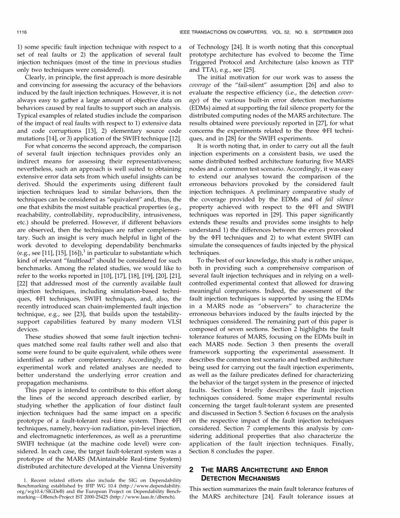
This study uses a single-board implementation of theMARS nodes. Each node consists of two independentprocessing units: the application unit and the communica-tion unit (Fig. 1). Each unit is based on a 68070 CPU [31],that features a memory management unit (MMU). Theapplication unit also contains a dynamic RAM and twobidirectional FIFOs, one of which serves as an interface toexternal add-on hardware, the other one connecting theapplication unit to the communication unit. Additionalhardware for the communication unit is comprised of aStatic RAM, two ethernet controllers (LANCEs), eachcoupled to a Clock Synchronization Unit (CSU) for
maintaining a global time base, and a Time Slice Controller(TSC) for controlling access to the system bus.
Whenever an error is detected, the subsequent errorprocessing activity of the node is to save the errorinformation into nonvolatile memory and then turn itselfoff. Upon restart, the node writes its previously saved errorinformation to two serial ports (one for each unit), fromwhere it can be read for the purpose of diagnosis. Thisfeature was exploited in the context of this study toprecisely monitor and characterize the consequence of theinjected faults. More details on MARS features and on thearchitecture of the processing nodes can be found in [24].
Three levels of error detection mechanisms (EDMs) areimplemented in the MARS nodes: 1) the hardware EDMs,2) the system software EDMs implemented in the operatingsystem [24] and support software (i.e., the Modula/Rcompiler) [32], and 3) the application-level (end-to-end)EDMs at the highest level. They are respectively describedin the following paragraphs.
2.3 Hardware Error Detection Mechanisms
Whenever an error is detected by one of the hardwareEDMs, in general, an exception is raised and the two CPUswill then wait for a reset issued by a watchdog timer. Thiswatchdog timer is the only device that may cause a reset ofall devices, including the CPUs.
Two main categories of hardware EDMs can be distin-guished: the built-in mechanisms of the CPUs and thoseprovided by special hardware on the processing board. Inaddition, faults can also trigger “unexpected” exceptions(i.e., neither the EDMs built into the CPUs nor themechanisms provided by special hardware are mapped tothese exceptions).
The EDMs built into the CPUs are: bus error, address error,illegal op-code, privilege violation, zero-divide, stack formaterror, noninitialized vector interrupt, and spurious interrupt.These errors cause the processor to jump to the appropriateexception handling routines, which save the error state to thenonvolatile memory and then reset the node.
The following errors are detected by mechanismsimplemented by special hardware on the node: silentshutdown of the CPU of the communication unit, powerfailure, parity error, FIFO over/underflow, access tophysically nonexisting memory, write access to the real-time network at an illegal point in time (monitored by theTSC), error of an external device, and error of the other unit.We globally call these “NMI mechanisms” as they raise a
ARLAT ET AL.: COMPARISON OF PHYSICAL AND SOFTWARE-IMPLEMENTED FAULT INJECTION TECHNIQUES 1117
Fig. 1. Block diagram of the processor board.
Non-Maskable Interrupt (a specific exception number)
when an error is detected. An NMI leads to the same error
handling as EDMs built into the CPUs and can only be
cleared by resetting the node, which is carried out by the
watchdog timer.
2.4 System Software Error Detection Mechanisms
These mechanisms consist of EDMs implemented by the
operating system or special system tasks; they include:
. assertions built into the operating system (OS), suchas integrity checks on data or processing timeoverflow,
. mechanisms inserted by the compiler (i.e., CompilerGenerated Run-Time Assertions—CGRTA) to im-plement concurrent checks, such as value rangeoverflow of a variable and loop iteration boundoverflow.
When an error is detected by any of these mechanisms, a
“trap” instruction is executed that leads to a node reset.
2.5 End-to-End Error Detection Mechanisms
These mechanisms include end-to-end checksums for mes-
sage data and multiple (basically, double) execution of tasks.The end-to-end checksums are used to detect the
mutilation of message data exchanged between two nodes
of an FTU and are therefore used by the receiving task for
extending the fail silence property of the MARS nodes.Double execution of tasks in time redundancy can detect
errors caused by transient faults that cause different output
data of the two instances of the task. Combined with the
concept of message checksums, task execution in time
redundancy forms the highest level in the hierarchy of the
error detection mechanisms. These mechanisms also trigger
the execution of a trap instruction, which causes a reset of
the node.
3 OVERVIEW OF THE EXPERIMENTAL FRAMEWORK
In this section, we first present the common testbed set-up
and workload implemented at all sites for carrying out the
experiments. Then, we precisely define the failure pre-
dicates considered during the fault injection experiments.
3.1 The Experimental Testbed and Workload
As depicted in Fig. 2, the common distributed testbed that is
supporting the fault injection experiments features five
MARS nodes.The node under test (NUT, for short) is the node subject
to the injection of a fault during each experiment run.
Another node (golden node) serves as a reference and a third
node (comparator node) is used to compare the messages
sent by the two previous nodes. When a discrepancy is
observed by the comparator node (fail silence violation) or
the NUT detects an error, the NUT is declared to be failed
and then shut down by the comparator node to clear all
error conditions for the subsequent experiment run. After
some time, power is reinstalled and the NUT is reloaded for
the next experiment run. The data generation node simulates
the data corresponding to the real-time application that is
being used to activate the NUT and the golden node duringeach fault injection experiment.
The application is taken from the rolling ball demonstra-tion [33]: A ball is kept rolling along a circular path on atiltable plane by controlling the two horizontal axes of theplane by servo motors and observing the position of the ballwith a video camera. However, the tiltable plane and thecamera are not present in the set-up used in the faultinjection experiments; instead, the data from the camera issimulated by a data generation task running on the datageneration node. The task provides the nominal and actualvalues of the position, speed, and acceleration of the ball.
A fifth node is included that serves as a gateway betweena local area network (LAN) and the MARS network. It isrequired for loading the entire application and for reloadingthe NUT. A host computer (Unix workstation) connected tothe LAN is used for supervising the experiments, i.e.,reloading failed nodes and collecting data from eachexperiment run for further analysis.
Fig. 2 also depicts the specific interactions with the �FIdevices. The experiments are managed by the workstationand controlled by the comparator node. When the com-parator node detects an error, it reports the error type to theworkstation and turns off the power to the NUT with thesignal P-NUT. Signal F-NUT is used to discontinue faultinjection.2 Then, the NUT is powered-up again andrestarted. Upon restart, the memorized error data is sentto the workstation via two serial lines (one for eachprocessing unit).3 Once the NUT has been restarted, theworkstation immediately initiates the downloading of theapplication via the gateway node. When the application hasbeen restarted, the comparator node enables fault injection(signal F-NUT) and a new experiment run begins.
Finally, it is worth noting that the experimental set-up isbased on the assumption that the nodes are replicadeterminate (both in value and in time domains), i.e., ifprovided with the same input data, replicated nodes deliveridentical outputs in an identical order within a specifiedtime interval. In particular, extensive runs without faultinjection of the rolling-ball target application have demon-strated that the MARS prototype architecture supported
1118 IEEE TRANSACTIONS ON COMPUTERS, VOL. 52, NO. 9, SEPTEMBER 2003
2. Such a direct control on the injected fault is not possible in the case ofthe software-implemented fault injection technique used (see Section 4.4).
3. If the error was not detected by the NUT itself, then the node has noerror information available and sends only a status message.
Fig. 2. The testbed architecture featuring five MARS nodes.
this property. Besides its interest for handling replicatedentities in real-time fault-tolerant systems (e.g., see [34]),such a feature proved very useful in the context of the faultinjection experiments so that the faulty behaviors betweenthe testbed instances used for supporting each faultinjection technique could be meaningfully compared.
3.2 The Failure Predicates
Four failure types can be distinguished for the NUT:
1. The EDMs detect an error and the node stopssending messages on the MARS bus; then, the nodestores the error condition into a nonvolatile memoryand resets itself by means of the watchdog timer.
2. The node fails to deliver the expected applicationmessage(s) for one or several application cycles, butno error is detected by the EDMs.
3. The node delivers a syntactically correct messagewith erroneous content. This is a fail silence violationin the value domain, which is recognized as amismatch between the messages sent by the NUTand the golden node.
4. The node sends a message at an illegal point in timeand thus disturbs the traffic on the MARS bus. Thisis a fail silence violation in the time domain.
On every restart, the NUT writes its previously savederror data, if available (i.e., if an error was detected by theEDMs) and data about its state to two serial ports, where itcan be read and stored for further processing. From thesedata, five predicates (events) can be derived (Table 1).
The Cold Start (CS) predicate characterizes the end ofeach data set. The other four predicates characterize fourfailure types. The assertion (occurrence) of the Warm Start(WS) predicate in the data corresponds to the normal casewhen the node under test detects the error (failure type 1).The assertion of ML corresponds to a Message Loss (failuretype 2); this behavior is not a fail silence violation becauseno erroneous data is sent, but it cannot be regarded asnormal operation. Irrespective of the other events, theassertion of a Message Mismatch (MM) (failure type 3)corresponds to a fail silence violation (in the data domain).There are two ways in which a System Failure (SF) mayoccur: 1) A fail silence violation in the time domain (failuretype 4) affects the operation of the other nodes, or 2) anothernode than NUT experiences a real hardware failure duringthe experiments. Although, no SF-type failures wereobserved in the conducted experiments, this failure eventis described for the sake of completeness.
Given these failure types, the number of fail silence (FS)violations can be counted as:
#FS Viol: ¼ #Exp: MMþ#Exp: SF;
where # Exp. X counts the number of experiments where anX-type failure was diagnosed (i.e., predicate X wasasserted).
4 THE FAULT INJECTION TECHNIQUES
In this section, we briefly present the main features of thefour fault injection techniques applied for the experimentalassessment of the MARS system.
4.1 Heavy-Ion Radiation
The fault injection experiments with heavy-ion radiation(HI, for short) were carried out at Chalmers University ofTechnology in Goteborg, Sweden. Heavy-ion radiation froma Californium-252 source can be used to inject single eventupsets, i.e., bit-flips at internal locations in integratedcircuits (ICs) using a miniature vacuum chamber. Fig. 3depicts the cross-sectional view of the miniature vacuumchamber. The pins of the target IC are extended through thebottom plate of the vacuum chamber so that the chamberwith the circuit can be directly plugged into the socket ofthe circuit under test. The vacuum chamber contains anelectrically controlled shutter, which is used to shield thecircuit under test from radiation during bootstrapping.
A major feature of the heavy-ion fault injection techniqueis that faults can be injected into VLSI circuits at locationswhich are difficult (and mostly impossible) to reach byother techniques. The transient faults produced are alsoreasonably well spread at random locations within an IC asthere are many sensitive memory elements in most VLSIcircuits. As device feature sizes of integrated circuits areshrinking, radiation induced bit-flips, also known as softerrors, are becoming an increasingly important source of
ARLAT ET AL.: COMPARISON OF PHYSICAL AND SOFTWARE-IMPLEMENTED FAULT INJECTION TECHNIQUES 1119
TABLE 1The Basic Predicates
Fig. 3. Cross-sectional view of the miniature vacuum chamber.
failures in computer systems, e.g., see [36], [37]. While softerrors are caused mainly by heavy ions in space, at groundlevel and airplane flight altitudes, they are instead causedby atmospheric neutrons [38].
Although the heavy-ions emitted from Cf-252 do notprovide a perfect imitation of the impact of either heavyions in space or neutron radiation on earth (e.g., withrespect to the ratio between multiple and single bit upsets),the method provides a practical approach to evaluating theeffectiveness of error detection and recovery mechanismswith respect to soft errors. Exposing circuits to neutronradiation is less practical since it involves placing the testedsystem in a room with concrete shielding [39].
For the 68070 CPU, the heavy-ions from Cf-252 mainlyprovoke single bit upsets; the percentage of multiple biterrors induced in the main registers was found to be lessthan 1 percent in the experiments reported in [40]. Theheavy-ion method has been previously used to evaluateseveral hardware and software-implemented error detec-tion mechanisms for the MC6809E microprocessor. Acomprehensive description of these experiments using theheavy-ion fault injection technique is given in [2].
4.2 Pin-Level Injection
Pin-level fault injection, i.e., the injection of faults directlyon the pins of the ICs of a prototype, probably was the mostwidely applied physical fault injection technique. Someflexible tools supporting general features have been devel-oped (e.g., see the test facility used on the MAFT system[41], MESSALINE [1], RIFLE [42], or AFIT [43]).
The experiments with the pin-level fault injectiontechnique were conducted at LAAS-CNRS, in Toulouse,France, using MESSALINE. Fig. 4 depicts the principle ofthe pin-forcing technique (PF, for short) that was used. Inthe case of pin-forcing, the injected fault is directly appliedon the pin(s) of the target IC.
It is noteworthy that the pins of the ICs connected, bymeans of an equipotential line, to an injected pin are faultedas well. Accordingly, to simplify the accessibility to the pinsof the microprocessor, the target ICs were mainly the bufferICs directly connected to it. The supported fault modelsinclude temporary stuck-at faults affecting single or multi-ple pins. Indeed, temporary faults injected on the pins of theICs can simulate the consequences of internal faults on thepins of the faulted IC(s).
The tool already contributed to the experimental assess-ment of two fault-tolerant systems: 1) for testing thediagnosis features of a computerized railway interlockingsystem and 2) for evaluating the fail silence property of theDelta-4 fault-tolerant architecture [1], [30].
4.3 Electromagnetic Interferences
Electromagnetic interferences (EI) are common distur-
bances in automotive vehicles, trains, airplanes, or indus-
trial plants. Such a technique is widely used to stress digital
equipment.The EI experiments were carried out at the Technical
University of Vienna, Austria. Thanks to the use of a
commercial burst generator, this technique is easy to
implement. Two different forms of application of this
technique were considered (Fig. 5).In the first form, the single computer board of the NUT was
mounted between two metal plates connected to the burst
generator. In this way, the entire node was affected by the
generated bursts. Because the Ethernet transceivers turned
out to be more sensitive to the bursts than the node under test
itself, a second configuration was set up which used a special
probe that was directly placed on top of the target circuit. In
this way, the generated bursts affected only the target circuit
(and some other circuits located near the probe).
4.4 Software-Implemented Fault Injection
Software-implemented fault injection (SWIFI) provides a
low cost and easy-to-control alternative to the three physical
fault injection techniques previously described that require
special hardware instrumentation and interfaces to the
target system. SWIFI is usually achieved by changing the
contents of memory or registers based on specified fault
models to emulate the consequences of hardware faults or
to inject software faults (e.g., see [9]).For these experiments, an alternative approach was
selected that injected the faults at preruntime at the machine
code level and loaded the mutilated application (code
segment or data segment) to the target system afterward.
Three main reasons led us to select such an approach [28]:
1. The intrusiveness is reduced to a minimum sincefaults are injected only into the application software(no additional code, which could probably alter thebehavior of the application software, is needed, i.e.,fault injection is transparent to the application),
2. Fault injection at the machine code level is capableof injecting faults which cannot be injected athigher levels by using source code mutations (e.g.,see [44], [45]).
3. Preruntime injection smoothly integrates with theapplication development process because applica-tions are developed, configured, allocated, andscheduled offline on a host computer and loadedonto the target system afterward.
SWIFI experiments started at the Vienna University of
Technology, Austria, and continued at the Research and
1120 IEEE TRANSACTIONS ON COMPUTERS, VOL. 52, NO. 9, SEPTEMBER 2003
Fig. 4. Principle of pin-forcing fault injection.
Fig. 5. Application of electromagnetic interferences.
Technology Institute of Daimler Benz AG (now Daimler-
Chrysler) in Berlin, Germany [46].The way the fault injection experiments are conducted
differs slightly from the �FI experiments for which faults
are injected until the injected node (NUT) fails. Indeed, this
is not a feasible solution for SWIFI: Faults are likely to be
overwritten before being activated or to be injected at
locations that are not executed. In such cases, the NUT
would continue operation infinitely. Accordingly, a time-
out mechanism has been implemented in order to shut
down the NUT after a prespecified time interval.
5 RESULTS OBTAINED WITH EACH FAULT
INJECTION TECHNIQUE
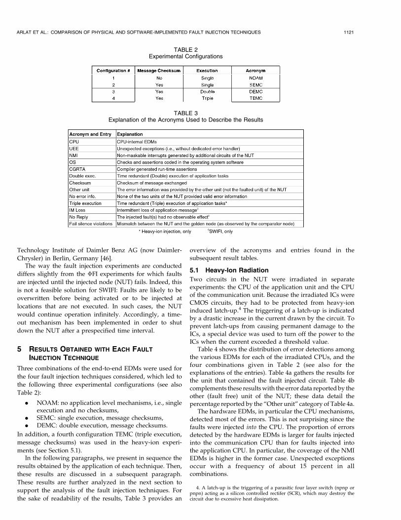
Three combinations of the end-to-end EDMs were used for
the four fault injection techniques considered, which led to
the following three experimental configurations (see also
Table 2):
. NOAM: no application level mechanisms, i.e., singleexecution and no checksums,
. SEMC: single execution, message checksums,
. DEMC: double execution, message checksums.
In addition, a fourth configuration TEMC (triple execution,
message checksums) was used in the heavy-ion experi-
ments (see Section 5.1).In the following paragraphs, we present in sequence the
results obtained by the application of each technique. Then,
these results are discussed in a subsequent paragraph.
These results are further analyzed in the next section to
support the analysis of the fault injection techniques. For
the sake of readability of the results, Table 3 provides an
overview of the acronyms and entries found in thesubsequent result tables.
5.1 Heavy-Ion Radiation
Two circuits in the NUT were irradiated in separateexperiments: the CPU of the application unit and the CPUof the communication unit. Because the irradiated ICs wereCMOS circuits, they had to be protected from heavy-ioninduced latch-up.4 The triggering of a latch-up is indicatedby a drastic increase in the current drawn by the circuit. Toprevent latch-ups from causing permanent damage to theICs, a special device was used to turn off the power to theICs when the current exceeded a threshold value.
Table 4 shows the distribution of error detections amongthe various EDMs for each of the irradiated CPUs, and thefour combinations given in Table 2 (see also for theexplanations of the entries). Table 4a gathers the results forthe unit that contained the fault injected circuit. Table 4bcomplements these results with the error data reported by theother (fault free) unit of the NUT; these data detail thepercentage reported by the “Other unit” category of Table 4a.
The hardware EDMs, in particular the CPU mechanisms,detected most of the errors. This is not surprising since thefaults were injected into the CPU. The proportion of errorsdetected by the hardware EDMs is larger for faults injectedinto the communication CPU than for faults injected intothe application CPU. In particular, the coverage of the NMIEDMs is higher in the former case. Unexpected exceptionsoccur with a frequency of about 15 percent in allcombinations.
ARLAT ET AL.: COMPARISON OF PHYSICAL AND SOFTWARE-IMPLEMENTED FAULT INJECTION TECHNIQUES 1121
TABLE 2Experimental Configurations
TABLE 3Explanation of the Acronyms Used to Describe the Results
4. A latch-up is the triggering of a parasitic four layer switch (npnp orpnpn) acting as a silicon controlled rectifer (SCR), which may destroy thecircuit due to excessive heat dissipation.
Errors detected by the Operating System (OS) mechanismsdominate the “System software” EDMs, while detection bythe message checksums dominate the “End-to-end” EDMs.
Percentages for fail silence violations were between2.4 percent and 0.5 percent for the NOAM, SEMC, andDEMC combinations when faults were injected into theapplication CPU. As expected, the number of fail silenceviolations is lower for SEMC than for NOAM and evenlower for DEMC. Moreover, when faults were injected intothe communication CPU, one single fail silence violationwas observed (for NOAM).
The percentage of fail silence violations (0.5 percent)observed for the DEMC combination was unexpected. Inprinciple, all effects of transient faults should be masked bythe double execution of tasks. One hypothesis for explain-ing these violations is that, despite the specific protectiondevice used, an undetected latch-up caused the sameincorrect result to be produced by both executions of thecontrol task. To further investigate this hypothesis, experi-ments were carried out with the TEMC combination thatused a third time-redundant execution of the control taskwhich was provided with fixed input data for which theresults were known. This made it possible to detect errorsby comparing the produced results with the correct results.This mechanism, which can be viewed as an online testprogram, would detect any semipermanent fault such as the
one suggested by the latch-up hypothesis. The results showthat no fail silence violations occurred for the TEMCcombination. As Table 4a shows, 0.8 percent of the errorswere detected by the third execution of the control task.This result comes in support of the latch-up hypothesis.However, our experimental set-up does not providesufficient observability to fully prove the latch-up hypoth-esis. In principle, the absence of fail silence violations couldalso be an effect of the change of the software configurationcaused by the switch from DEMC to TEMC and the errorsdetected by the third execution may have been caused byregular transients. Verification of the latch-up hypothesiswould require the use of a logic analyzer so that theprogram flow and behavior of the microprocessor could bestudied in detail.
The OS and NMI EDMs dominate the detections madeby the other unit of the NUT. The communication betweenthe two units is done via two FIFO buffers (see Fig. 1) andnearly all of these detections are made by EDMs signalingempty FIFO. (An empty FIFO can be detected both by theexecutive software and the special NMI mechanism.)
5.2 Pin-Level Injection
The forcing technique was used for the experiments carriedout on the MARS system. The main characteristics of theinjected faults are listed hereafter:
1122 IEEE TRANSACTIONS ON COMPUTERS, VOL. 52, NO. 9, SEPTEMBER 2003
TABLE 4Results for Heavy-Ion Radiation: (a) Detection by the EDMs of the Unit to Which the Faulted ICs Belong;
(b) Detection by the EDMs of the Other Unit (Detail of “Other Unit” in (a))
. One single IC was fault injected at a time (themaximum number of pins faulted simultaneously—i.e., the multiplicity of the fault—being limited tomx ¼ 3),
. Uniform distribution over all combinations of mxpins out of the n functional pins of the target IC wasused to select the mx faulted pins,
. Stuck-at-0 and -1 fault models (all 0-1 combinationsof mx pins were considered equally probable),
. To facilitate the comparison with the other techni-ques, both transient and intermittent (series oftransients) faults were injected.
As a consequence of the application of the pin-forcing
technique, it can be confidently considered that all pins of
the ICs connected to an actually injected pin are equally
faulted. Accordingly, to simplify the accessibility to the pins
of the CPUs of the application and communication units,
the target ICs were mainly buffer ICs connected to them. As
a result, seven ICs (five on the application unit and two on
the communication unit) were tested. These tests resulted in
3,266 error reports.Table 5 shows the distribution of the errors detected by
the various EDMs, together with their percentage of the
total number of errors observed in each experimental
configuration.
The results in Table 5a indicate a dominant proportion of
detections by the hardware EDMs (more than 90 percent on
the application unit side and 75 percent on the commu-
nication unit side). NMIs clearly dominate; however, in
addition to CPU exceptions, a significant number of UEEs
were also triggered. The difference between UEE and NMI
for the application and communication units can be
explained by the fact that not all ICs tested on the
application unit are directly connected to the processor. In
the “System software” category, the OS EDMs significantly
dominate. Concerning the “End-to-end” level, the “Check-
sum” detections significantly dominate: No detections were
triggered by the “Double execution” when this option was
enabled. Only a limited number of fail silence violations
were observed: two occurrences for the SEMC combination
when injecting on the application unit and one occurrence
for the NOAM combination when injection targeted the
communication unit.Table 5b shows that NMI EDMs also dominate the
supplementary detections observed on the other unit. A
significant difference is observed between the results of
whether the injection affects the application unit or the
communication unit; this may indicate that a larger
proportion of errors was propagated to the application unit.
ARLAT ET AL.: COMPARISON OF PHYSICAL AND SOFTWARE-IMPLEMENTED FAULT INJECTION TECHNIQUES 1123
TABLE 5Results for Pin-Forcing Injection: (a) Detection by the EDMs of the Unit to Which the Faulted ICs Belong;
(b) Detection by the EDMs of the Other Unit (Detail of “Other Unit” Entry in (a))
5.3 Electromagnetic Interferences
Various fault injection campaigns were carried out with avariety of voltage levels, with negative or positive polarityof the bursts, and with a burst-frequency of 2.5 kHz and10 kHz. A total number of more than 17,000 errors wereobserved during all campaigns conducted with the firstmethod, i.e., when the computer board of the node undertest was mounted between two plates, and more than 30,000errors were observed using the special probe (seeSection 4.3). Most of the campaigns were conducted withall application level EDMs enabled.
In the first campaign of Table 6 (identified as NOAM(1)),faults were injected into the communication unit using thetwo plates. Antenna wires were attached to the so-calledLO-EPROM in order to disturb the address bus and theeight low order bits of the data bus. Bursts characterized bya frequency of 2.5 kHz, negative polarity, and a voltage of230 V were injected. The second campaign (SEMC(2)) usedthe special probe, with antenna wires connected to theLO-EPROM in the application unit. In this case, the burstswere characterized by a frequency of 10 kHz, negativepolarity and a voltage of 300 V. Campaign number three(DEMC(3)) used the two plates, the bursts had a frequencyof 2.5 kHz, negative polarity, and voltage of 230 V. Thewires were attached to the LO-EPROM of the applicationunit. Campaigns 4 to 6 were only using the special probe for
coupling faults into the CPU of the application unit, i.e., theprobe was mounted on top of the CPU and no wires wereattached to any chip. The chosen frequency for the burstswas 10 kHz and negative polarity was used for all theseexperiments. We used a voltage of 290 V for campaigns 4and 6, while a slightly higher voltage, 300 V, was used forcampaign 5.
Due to the large number of campaigns made, onlyselected campaigns are presented in Table 6, which showsthe distribution of the errors detected by the various EDMsas total numbers and as percentage. Table 6a shows theerrors detected by the unit where fault injection wasfocused to; errors detected by the other unit of the NUTare detailed in Table 6b.
Campaigns 1 and 2 show similar results, although focusof fault injection was on different units of the NUT, thecommunication unit for the first and the application unit forthe second. Most of the errors were detected by thehardware EDMs, where the CPU EDMs clearly dominate.For the “system software” EDMs, which only detected asmall fraction of the errors, the OS category dominates. Therelatively high amount of occurrences of the “No errorinfo.” category for campaign 1 partly results from the factthat, for this campaign, no information about the errorsdetected by the application unit is available because this is aresult from early experiments, where only the outputs of the
1124 IEEE TRANSACTIONS ON COMPUTERS, VOL. 52, NO. 9, SEPTEMBER 2003
TABLE 6Results for Electromagnetic Interferences: (a) Detection by the EDMs of the Unit to Which the Faulted ICs Belong;
(b) Detection by the EDMs of the Other Unit (Detail of “Other Unit” Entry in (a))
unit under test were recorded and, therefore, all errors thatwere detected by the application unit are counted as “Noerror info.”.
A singular distribution of error reports was observed forcampaign 3. There, the system software EDMs (especiallyOS) detected most of the errors. Most reports pointed outthat a message which was required by the application waslost. Although both campaigns 1 and 3 used the “two metalplates” technique, the observed results are quite different.Conversely, while campaigns 1 and 2 had different EIconditions, the results observed are very similar. Thisobservation and the unique feature of the results obtainedduring campaign 3 led us to consider them suspiciously.More generally, significantly different results were ob-served for similar conditions, e.g., slight changes in voltagelevels. Thus, reproducibility appears to be problematic forEI experiments.
For campaigns 4 to 6, almost all of the errors weredetected by the CPU EDMs. Only campaign 5 shows a smallamount of errors detected by other EDMs than hardwareEDMs. When looking at the results of campaigns 4 to 6 inmore detail, we discovered that almost all of the detectederrors were spurious interrupts detected by the CPU.Spurious interrupts are interrupts signaled to the processor,but the processor cannot find the source of the interrupt,i.e., the device having raised the interrupt. This shows thatthe interrupt lines of a processor are highly sensitive to EI.
For all campaigns, errors detected by the “Other unit”were only detected by the NMI EDMs and by the OS EDMs.
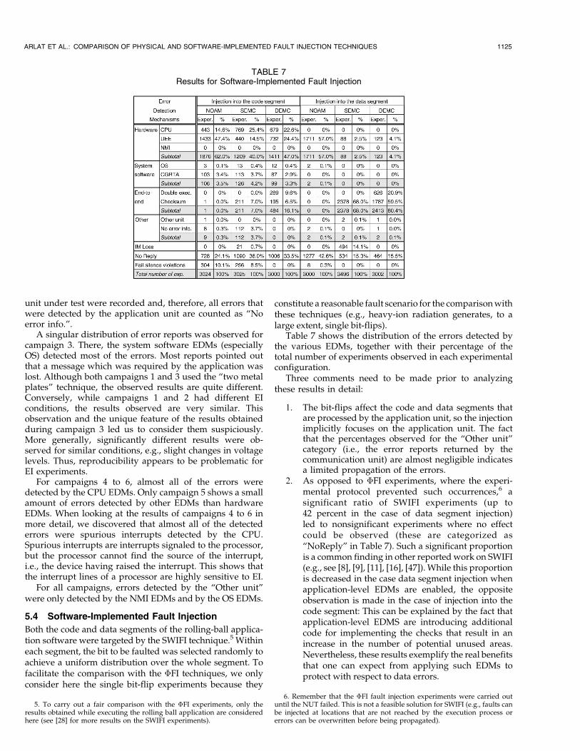
5.4 Software-Implemented Fault Injection
Both the code and data segments of the rolling-ball applica-tion software were targeted by the SWIFI technique.5 Withineach segment, the bit to be faulted was selected randomly toachieve a uniform distribution over the whole segment. Tofacilitate the comparison with the �FI techniques, we onlyconsider here the single bit-flip experiments because they
constitute a reasonable fault scenario for the comparison withthese techniques (e.g., heavy-ion radiation generates, to alarge extent, single bit-flips).
Table 7 shows the distribution of the errors detected bythe various EDMs, together with their percentage of thetotal number of experiments observed in each experimentalconfiguration.
Three comments need to be made prior to analyzingthese results in detail:
1. The bit-flips affect the code and data segments thatare processed by the application unit, so the injectionimplicitly focuses on the application unit. The factthat the percentages observed for the “Other unit”category (i.e., the error reports returned by thecommunication unit) are almost negligible indicatesa limited propagation of the errors.
2. As opposed to �FI experiments, where the experi-mental protocol prevented such occurrences,6 asignificant ratio of SWIFI experiments (up to42 percent in the case of data segment injection)led to nonsignificant experiments where no effectcould be observed (these are categorized as“NoReply” in Table 7). Such a significant proportionis a common finding in other reported work on SWIFI(e.g., see [8], [9], [11], [16], [47]). While this proportionis decreased in the case data segment injection whenapplication-level EDMs are enabled, the oppositeobservation is made in the case of injection into thecode segment: This can be explained by the fact thatapplication-level EDMS are introducing additionalcode for implementing the checks that result in anincrease in the number of potential unused areas.Nevertheless, these results exemplify the real benefitsthat one can expect from applying such EDMs toprotect with respect to data errors.
ARLAT ET AL.: COMPARISON OF PHYSICAL AND SOFTWARE-IMPLEMENTED FAULT INJECTION TECHNIQUES 1125
TABLE 7Results for Software-Implemented Fault Injection
5. To carry out a fair comparison with the �FI experiments, only theresults obtained while executing the rolling ball application are consideredhere (see [28] for more results on the SWIFI experiments).
6. Remember that the �FI fault injection experiments were carried outuntil the NUT failed. This is not a feasible solution for SWIFI (e.g., faults canbe injected at locations that are not reached by the execution process orerrors can be overwritten before being propagated).
3. Another singular behavior was the intermittentomission of application messages (“IM Loss” cate-gory). Such a singular behavior was quite significantin the case of data segment injection (14 percent)!Analysis of the cause was traced to the mutilation ofthe time-stamp information incorporated into theend-to-end CRC (see [29] for more details).
The first observation is that the behaviors highly dependon the type of segment targeted by fault injection. While theproportion of hardware error detections dominates in thecase of code segment injection, this is no longer the case fordata segment injection experiments: On the contrary, end-to-end EDMs significantly dominate. Moreover, especiallyin the NOAM configuration, the type of hardware EDMsexercised highly depend on the type of segment targeted byfault injection: While CPU EDMs were exercised frequentlyin the case of code segment injection, only UEEs have beenobserved for data segment injection.
Another interesting difference between the target seg-ments concerns the system software EDMs: Indeed, ascould be expected, these do not contribute (nearly at all) tothe detection in the case of data segment injection. Also,occurrences of fail silence violations were significantlyhigher for code segment injection. However, in both cases,the utilization of end-to-end EDMs (especially, doubleexecution7) in addition to hardware and system softwareEDMs proved useful to eliminate this risk.
5.5 Discussion
We synthesize here the results related to the evaluation ofthe efficiency of the various EDMs implemented in theMARS architecture. In particular, these results provideobjective insights to the designers in getting confidence inthe way the fail silence property of the computing nodeshas been achieved. The analysis focuses on the comple-mentarity of the EDMs in contributing to the fail silenceproperty. The detailed analysis of the different erroneousbehaviors provoked by the fault injection techniquesconsidered is presented in Section 6.
Most �FI fault injection campaigns show that thehardware EDMs significantly detect most of the errors.8
Conversely, the impact of hardware EDMs is much lessimportant in the case of the SWIFI experiments. Further-more, the target segment (code or data) has a dramaticimpact on the type of mechanisms exercised (and thus onthe type of errors generated). Accordingly, these twotechniques will be considered separately in the analysescarried out in Section 6.
A closer examination of the errors detected by thehardware EDMs revealed that 5.0 percent, 11.6 percent, and1.9 percent of the errors were detected by the time-slicecontroller (TSC)—that is, triggering an NMI—for heavy-ion,pin-forcing, and EI, respectively. Although no NMIs wereobserved during the SWIFI experiments reported here, a
small number of NMIs generated by the time-slice con-troller were observed during other experiments. No failsilence violations in the time domain (see Section 5.4) wereobserved during these experiments, thus demonstrating theusefulness of this error detection mechanism.
The system software EDMs detected the second largestamount of errors for all the �FI techniques. The imbalanceobserved in the case of heavy-ion radiation between the OSand CGRTA EDMs is amplified when using pin-forcing andEI: Almost no detections by the CGRTAs were observed forthe two latter techniques. For SWIFI, on the contrary, theCGRTA EDMs dominate, but the overall impact of thesystem software EDMs is significantly reduced.
The application-level (end-to-end) EDMs detected thesmallest amount of errors for all �FI techniques. This isopposite for the SWIFI technique. However, when thesewere disabled, the fail silence coverage was significantlyreduced (particularly for heavy-ion radiation and SWIFI oncode segment), which shows the necessity of using thesemechanisms as well.
Another important outcome of the study concerned theanalysis of the impact of the various EDMs on the fail silenceproperty of a MARS node. The results shown for eachtechnique in the previous tables, where three configurationsinvolving, respectively, both (DEMC), only one (SEMC), ornone (NOAM) of the end-to-end EDMs are presented,sustain the conviction that the end-to-end EDMs play adominant role (with respect to the other EDMs) in achievingthe fail silence property. To further check this view, aspecific series of experiments was carried out for HI and PFfor which the NMI EDMs were disabled. These experimentsfocused essentially on the application unit processor. Theresults can be summarized as follows: In both cases, almostno fail silence violations were observed for the DEMCconfiguration (with NMI disabled), while, as shown inTables 5 and 6, the NOAM configuration (with NMIenabled) exhibited a significant number of fail silenceviolations.
6 ANALYSIS OF THE FAULT INJECTION TECHNIQUES
This section provides a detailed study of the actual impactof the fault injection techniques considered. Indeed, each setof experiments carried out using a specific fault injectiontechnique can be considered as a kind of “benchmark” toassess the relative effectiveness of the various EDMs. Onthose grounds, the distribution of the sensitization amongthe various EDMs and failure modes, as well as among theerror data observed for each experiment, constitute suitable—albeit, indirect—means to identify the similarities anddifferences of the error sets induced by the four injectiontechniques considered.
If, when applying two techniques, the observed error setsare nearly the same, then the technique that is the mostexpensive or the most difficult to control may be substitutedby the other one. Conversely, if the error sets differ to alarge extent, the fault injection techniques may instead beused to complement each other. Some insights on theadditional properties characterizing the fault injectiontechniques considered are provided in Section 7.
1126 IEEE TRANSACTIONS ON COMPUTERS, VOL. 52, NO. 9, SEPTEMBER 2003
7. Note that each of the two task instances executed has its own code anddata segment. Therefore, injection of a single error in one of the taskinstances is very likely to be detected (this was also confirmed by theexperiments consisting of multiple bit-flips [28]).
8. This is true for all �FI campaigns, except for EI campaign DEMC(3) inTable 5. As already pointed out, this campaign exhibited results which weredrastically different from the other EI campaigns. Accordingly, this led us tosuspect it, so we prefer to exclude these results from subsequent analyses.
In the sequel, we revisit the results from Section 5 by
comparing the impact of the variation of the experimental
configuration (combining the end-to-end EDMs) on the
observation of fail silence violations, as well as of the three
levels of EDMs included in the NUT—namely, hardware,
system software, and end-to-end—for each injection tech-
nique. For the �FI techniques—heavy-ion (HI), pin forcing
(PF), and electromagnetic interferences (EI)—the error
reports concerning both the application unit and commu-
nication unit experiments have been merged. For SWIFI,
due to the notably different impact observed, we explicitly
distinguish the experiments targeting the segments of code
(SC) and data (SD). Furthermore, in the sequel, we focus the
analysis by considering only the actual error reports, i.e., the
“No Reply” category will be disregarded and the other
percentages are normalized accordingly. Also, the inter-
mittent “IMLoss” outcomes have been transferred to the
“Checksum” category (although some message losses were
observed, this misbehavior was eventually caught by this
error detection mechanism). More details on the results that
support this analysis can be found in [48] and [33], for the
�FI and SWIFI experiments, respectively.
6.1 Fail Silence Violations
Fig. 6 compares the impact of the fault injection techniques
for the different configurations of the end-to-end EDMs on
the observation of fail silence violations. As already pointed
out, the impact of the SWIFI technique depends strongly on
where the faults were injected in the rolling ball application
software: code (SC) or data (SD) segments. Injection in the
code segment generates significantly more fail silence
violations. Summarizing, SC appears to be more malicious
than the physical techniques both for the NOAM and SEMC
configurations, but HI is more stressful for the DEMC
configuration.
6.2 Hardware Error Detection Mechanisms
Fig. 7 compares the impact of the fault injection techniques on
the percentages of errors that activated the hardware EDMs.In the NOAM case, all techniques provide a large ratio of
hardware error detection (more than 70 percent). Although
an important percentage of hardware detections is main-
tained for the �FI techniques (and, to some extent, for
SWIFI on the code segment), when the application-level
EDMs are enabled, the percentages observed are signifi-cantly reduced for SD.
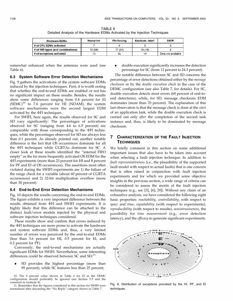
The significant difference observed for the two types offaults injected by the software technique is worth noting.For SC, this percentage is maintained above 60 percent,while, for SD, it is reduced to less than 5 percent. Thissuggests that the faults injected in the code segmentprovoke, rather control flow errors that (to a large extent)better simulate the consequences of hardware faults. TheSD experiments generate mainly data flow errors that aredifferent from the ones created by the other techniques.Nevertheless, it is interesting to note that SD can provide arather high level of activation of the hardware EDMs in theNOAM configuration, i.e., when the end-to-end mechan-isms are inhibited. A closer examination of the results wascarried out. Table 8 summarizes some of the maindifferences observed.
Concerning CPU EDMs, although, out of the eightmechanisms supported, a different number of mechanismswere activated, the same three mechanisms dominated (buserror, address error, and illegal opcode) for all the faultinjection techniques. The number of NMI types and of theircombinations (i.e., the simultaneous occurrences of severaltriggering events) vary significantly for the �FI techniques.9
The results indicate that PF may be more effective than theother techniques in exercising hardware EDMs locatedoutside of the CPU chip. Moreover, the most frequent NMIsobserved differ: While “unavailable memory” significantlydominates for HI (more than 60 percent), “memory parity”dominates for PF and EI (more than 50 percent). Both PFand EI also exhibited a significant proportion of NMIstriggered by the TSC (more than 15 percent). The differ-ences observed are further exemplified by the variations inthe number of different types of exceptions (including CPU-related and NMI) activated during the various experiments,out of the 255 possible exceptions. This is illustrated byFig. 8, which shows the distribution of the exceptionsobserved for the three �FI techniques considered.
However, it is worth noting that, for EI, most of theexperiments exercised CPU EDMs (especially when usingthe probe without antennas), which reveals the veryrestricted spectrum of the type of errors generated by thistechnique. However, the variation in the error set was
ARLAT ET AL.: COMPARISON OF PHYSICAL AND SOFTWARE-IMPLEMENTED FAULT INJECTION TECHNIQUES 1127
Fig. 6. Fail silence violations provoked. Fig. 7. Activation of the hardware EDMs.
9. As shown in Table 7, no NMIs were observed for the SWIFIexperiments reported here.
somewhat enhanced when the antennas were used (seeTable 6).
6.3 System Software Error Detection Mechanisms
Fig. 9 gathers the activations of the system software EDMsinduced by the injection techniques. First, it is worth notingthat whether the end-to-end EDMs are enabled or not hasno significant impact on these results. Besides, the resultsshow some differences ranging from 0.4 percent for EI(SEMC)10 to 7.6 percent for HI (NOAM), the systemsoftware mechanisms were the second largest EDMactivated by the �FI techniques.
For SWIFI, here again, the results observed for SC andSD vary significantly: The percentages of activationsobserved for SC (ranging from 4.6 to 6.5 percent) arecomparable with those corresponding to the �FI techni-ques, while the percentages observed for SD are always lessthan 0.1 percent. As already pointed out, another notabledifference is the fact that OS occurrences dominate for allthe �FI techniques while CGRTAs dominate for SC. Acloser look at these results identified the “internal FIFOempty” as the far more frequently activated OS EDM for the�FI experiments (more than 23 percent for HI and 8 percentfor PF and EI of OS occurrences). The assertions most oftenviolated during the SWIFI experiments are 1) the failure ofthe range check for a variable (about 60 percent of CGRTAoccurrences) and 2) 32-bit multiplication overflow (morethan 30 percent).
6.4 End-to-End Error Detection Mechanisms
Fig. 10 depicts the results concerning the end-to-end EDMs.The figure exhibits a very important difference between theresults obtained from �FI and SWIFI experiments. It ishighly likely that this difference can be attached to thedistinct fault/error models injected by the physical andsoftware injection techniques considered.
These results show and confirm that errors induced bythe �FI techniques are more prone to activate the hardwareand system software EDMs and, thus, a very limitednumber of errors was perceived by the end-to-end EDMs(less than 3.6 percent for HI, 0.5 percent for EI, and0.2 percent for PF).
Conversely, the end-to-end mechanisms are actuallysignificant EDMs for SWIFI. Nevertheless, some interestingdifferences could be observed between SC and SD:11
. SD provides the highest percentage (more than95 percent), while SC features less than 25 percent,
. double execution significantly increases the detectionpercentage for SC (from 12 percent to 24.3 percent).
The notable difference between SC and SD concerns the
percentage of error detections obtained either by the message
checksum or by the double execution check in the case of the
DEMC configuration (see also Table 7, for details). For SC,
double execution detects most errors (60 percent of end-to-
end detections), while, for SD, message checksum EDM
dominates (more than 70 percent). The explanation of this
last observation is that the message check is done at the start
of an application task, while the double execution check is
carried out only after the completion of the second task
instance and, thus, is likely to be dominated by message
checksum.
7 CHARACTERIZATION OF THE FAULT INJECTION
TECHNIQUES
We briefly comment in this section on some additional
important issues that also have to be taken into account
when selecting a fault injection technique. In addition to
fault representativeness (i.e., the plausibility of the supported
fault model with respect to actual faults) that is one concern
that is often raised in conjunction with fault injection
experiments and for which we provided some objective
insights in the previous section, a wide range of criteria can
be considered to assess the merits of the fault injection
techniques (e.g., see [3], [6], [9]). Without any claim of an
exhaustive analysis, we have considered the following eight
basic properties: reachability, controllability, with respect to
space and time, repeatability (with respect to experiments),
reproducibility (with respect to results), nonintrusiveness, the
possibility for time measurement (e.g., error detection
latency), and the efficacy to generate significant experiments.
1128 IEEE TRANSACTIONS ON COMPUTERS, VOL. 52, NO. 9, SEPTEMBER 2003
TABLE 8Detailed Analysis of the Hardware EDMs Activated by the Injection Techniques
10. The 0 percent value shown in Table 6 for EI in the DEMCconfiguration should preferably be ignored (see Section 5.5 and thecomment in footnote 8).
11. Remember that the figures considered in this section for SWIFI werenormalized after discarding the “No Reply” category shown in Table 7.
Fig. 8. Distribution of exceptions provoked by the HI, PF, and EI
techniques.
A characterization of the considered fault injectiontechniques based on these eight basic properties is shownin Table 9 and explained hereafter. For each property, thetechniques are graded on the scale none, low, medium, andhigh. It is worth noting that, although it is quite generic inscope, this analysis also builds upon insights gained duringthe experiments carried out on the MARS system. Noteagain that this characterization is meant to complement theanalysis of the impact of the injected faults, i.e., the errorsthat are produced. Finally, it is worth pointing out that sucha study is mainly a relative issue; accordingly, grading isvery dependent of the set of techniques being assessed;indeed, different grading could be obtained should othertechniques be considered.
7.1 Reachability
We consider the reachability property attached to a faultinjection technique to be defined as the ability to reachpossible fault locations in the ICs that implement the targetsystem.
From that perspective, heavy-ion radiation definitelysurpasses the other techniques as faults are actually injecteddirectly at the level of the physical devices that constitutethe irradiated circuit.
In the experiments conducted, pin-level fault injectionwas focused on the digital input/output signals. Accord-ingly, the corruption of data at the level of internal devicesis only indirect. This is why pin-level injection has beenrated with medium reachability (IC pins are targeted, butinjection cannot be focused on internal devices). Never-theless, varying reachability is obtained depending on the
level of integration for the target system: It is definitelymuch lower for highly integrated systems.
When using antennas, EI has similar physical reach-ability as pin-level injection as most faults probably areinjected via the digital input/output signals. However,faults may also impact internally the ICs as a result ofdisturbances propagated through the power supply lines.
SWIFI at preruntime directly corrupts the information(code or data) that will be stored in memory devices. Still, asopposed to runtime techniques (e.g., see [9]), this techniquecannot specifically target the lower hardware layers (e.g.,processor registers). Also, the injection targets are limited toinformation explicitly processed by the software layers ofthe computing system. Also, it provides low reachabilitywith respect to peripheral ICs. This is why the techniquewas graded “low to medium” with respect to this property.
7.2 Controllability
In this section, we consider controllability with respect toboth the space and time domains. The space domain relatesto the ability to control which of the reachable faultlocations are actually injected. The time domain corre-sponds to controlling the instant when faults are injected.
Heavy-ion radiation has low controllability for the spacedomain. In practice, faults could be confined to specificblocks of a circuit if the rest of the circuit is shielded.However, shielding was not used in this study. The time ofthe injection of a fault cannot be controlled as the decay ofthe Cf-252 source is governed by a random process.
Pin-level fault injection features good controllability in thespace domain. Indeed, selected ICs and pins can be targeted.Basically, some extent of time domain controllability can beachieved. Nevertheless, it may be hampered by theproblem of synchronizing the fault injection with the
ARLAT ET AL.: COMPARISON OF PHYSICAL AND SOFTWARE-IMPLEMENTED FAULT INJECTION TECHNIQUES 1129
Fig. 9. Activation of the system software EDMs.
Fig. 10. Activation of the end-to-end EDMs.
TABLE 9Properties of the Fault Injection Techniques Used
activity of the system, especially when the clock frequencyof the target system is high. Actually, controllability isvery much dependent upon the level of integration andclock speed of the target system. For the MARS system,which uses a mix of VLSI, LSI, MSI, and SSI circuits andmoderate clock speeds, controllability was, in fact, high.Nevertheless, high integration levels and high clock speedare the major limitations for the use of such a technique inmodern digital system designs.
Electromagnetic interferences feature low controllabilityin the space domain because faults may be injected incircuits surrounding the target circuit. The time of injectioncan (to some extent) be synchronized with system activity,but it is difficult to determine exactly when a fault isinjected.
SWIFI at preruntime procures a very high level ofcontrollability as it can focus selectively on specific codeand data segments. However, injection is limited toinformation processed by the software layers of thecomputing system. It is also worth pointing out that itprocures less time-domain controllability than runtimetechniques; accordingly, it was graded “medium to high”with respect to this property.
7.3 Repeatability
Repeatability refers to the ability to repeat experimentsexactly or with a very high degree of accuracy. Thisproperty is highly desirable, particularly when the aim ofthe experiments is to remove potential design/implementa-tions faults in the fault tolerance mechanisms (e.g., see [5]).Repeatability requires a high degree of controllability inboth the space and the time domains.
Preruntime SWIFI achieves a very high level of repeat-ability. Basically, the time-triggered architecture of MARSmade it possible to carry out a deterministic series ofexperiments.
For pin-level injection, it is possible to accurately repro-duce the injection of a selected fault with MESSALINE. Still,due to limited synchronization capabilities, this does notnecessarily imply that the errors being provoked are thesame. Such a difficulty in reproducing an experiment is evenmore stringent in the case of a distributed architecturebecause of the problem associated with controlling andsynchronizing the activities in multiple computers. However,the time-triggered architecture of the MARS system greatlyfacilitated such a synchronization.
Repeatability is very low, or nonexistent, for electro-magnetic interferences and heavy-ion injection due to lowcontrollability.
7.4 Reproducibility
Reproducibility refers to the ability to reproduce resultsstatistically for a given set-up. Reproducibility of results isan absolute requirement to ensure the credibility of faultinjection experiments. Repeatability normally implies re-producibility; if we can control an experiment exactly, thenit is always possible to also reproduce the results. However,reproducibility can be achieved without repeatability.
The experiments conducted in this study showed thatheavy-ion radiation produces results that are statisticallyreproducible among different specimens of the target circuits.
However, the lessons learned from this study also show thatstatistical reproducibility is difficult to obtain for theelectromagnetic interferences experiments (see Section 5.3).
7.5 Nonintrusiveness
This relates to the property of avoiding or minimizing anyundesired impact of fault injection on the behavior of thetarget system. The heavy-ion radiation technique has lownonintrusiveness since the target IC has to be removed fromthe main board and inserted into a vacuum chamber. Thismay cause unexpected delays in the data paths of theassociated logical signals.
This problem is significantly lower when using the pin-forcing technique.12 Nevertheless, even in the case of forcing,the extra load capacitances on the targeted logical signals thatare introduced by the connection of the injection probes mayalso alter the timing characteristics. The nonintrusiveness istherefore graded a medium for pin-forcing.
The EI technique with the probe features high nonintru-siveness since no physical connection is required betweenthe probe and target IC, although there may be difficultiesattached to actually focusing the injection to a specific IC.
As opposed to most runtime SWIFI techniques (e.g., see[8], [9], [11]), the preruntime SWIFI technique used herefeatures minimal intrusiveness.
7.6 Time Measurement
The acquisition of timing information associated to themonitored events (e.g., measurement of error detectionlatency) is an important outcome from fault injectionexperiments (e.g., see [49]).
For heavy-ion radiation, such measurements rely on theuse of the golden chip technique [2]. This requires the targetIC to be operated synchronously with a reference IC.However, this may not be possible for ICs with nondeter-ministic external behavior (caused, for example, by avarying number of wait states cycles inserted duringmemory accesses). This technique could not be used inthe experiments reported earlier.
For pin-level injection, the time of the injection of a fault(and activation of this fault as an error) can be explicitlyknown, thus, latency measurements does not pose aproblem [1].
For EI, latency measurements are difficult. In principle,the golden chip technique could also be used in this case,but it may be difficult to confine the disturbances to thetarget IC only.
Basically, in preruntime SWIFI, the fault is beingactivated when the flipped (code or data) word is accessed.Accordingly, trace analysis can be used to relate this eventwith the error detections in order to make timing measure-ments such as error detection latency. However, thisrequires an extensive data log and, possibly, a tediousanalysis. This was not considered in the experimentscarried out on the MARS system.
Due to the inherent difficulties described above for alltechniques (pin-level injection, excepted), no timing
1130 IEEE TRANSACTIONS ON COMPUTERS, VOL. 52, NO. 9, SEPTEMBER 2003
12. One should note that the same form of intrusiveness would apply topin-level injection when the insertion technique is used (in that case, the ICunder test is removed from the target system and solid-state switchesensure its proper isolation from the rest of the system).
measurements were made for the experiments conductedon the MARS system.
7.7 Efficacy
The type of efficacy considered here concerns the testingpower offered by the techniques, i.e., their ability toproduce a limited number of nonsignificant experiments.A nonsignificant experiment occurs, for example, when afault is injected into a hardware or software componentwhich is not accessed or used by the workload executedduring the experiment.
As shown in several previous studies, (e.g., see [1], [2],[43]), high efficacy is rather easy to achieve by �FItechniques. The key issue is to adjust the amplitude,duration, or intensity of the physical interferences to anappropriate level. This was also confirmed by the experi-ments carried out on the MARS system. Indeed, it was easyto devise an experimental protocol ensuring that all �FIexperiments result in significant experiments leading toactual, albeit possibly empty, error reports.
Conversely, as it focuses on specific information storedin the memory, the SWIFI technique is very prone togenerating nonsignificant experiments. The reason for thisis that random injections into the code or data segmentgenerate many errors that either become overwritten orremain latent throughout the experiment. As alreadypointed out in Section 5.4, this concern is reported in manyother related studies and was observed also in theexperiments conducted on MARS. Furthermore, as onecould anticipate, the efficacy of the preruntime techniqueused here highly depends on the memory segment targeted(either code or data) and also varies according to the type ofEDMs that are actually enabled.
The efficacy of SWIFI techniques could be improved byconducting preinjection analysis that determine which partsof the software (variables, constants, subroutines, etc.) aresensitive to fault injection. Examples of research in thisdirection can be found in [17] and [50].
8 CONCLUSION
This paper summarized the study concerning the analysisof the impact of four fault injection techniques that wasdeduced from the controlled experiments carried out onthe MARS architecture. Three physical fault injectiontechniques—heavy-ion radiation, pin-forcing, and electro-magnetic interferences—and preruntime software-imple-mented fault injection (SWIFI) were applied using thesame hardware/software set-up.
First, it is worth pointing out that these extensive sets ofexperiments significantly contributed to getting confidencein the ability of the MARS nodes to implement the “failsilence” property. It was shown that, beyond the hardwareand system software error detection mechanisms (EDMs),the application-level (end-o-end) EDMs are necessary forachieving a very high coverage on the fail silence assump-tion. Indeed, although the time-slice controller effectivelyprevents fail silence violations in the time domain, failsilence violations in the value domain were observed for allfour injection techniques when double execution of taskswas not used.
The other major outcome from the work that is reportedin this paper concerns the comparative analysis of the fault
injection techniques considered. We proposed a detailedstudy of the impact of the fault injection techniques on thebasis of the way they activated the various EDMs of theMARS architecture and also of the failure modes observed.This analysis showed that the four injection techniques arerather complementary, i.e., they generate, to a large extent,different types of errors.
In addition to this analysis, we also identified some basicproperties (e.g., reachability, repeatability, controllability,etc.) that characterize the application of the fault injectiontechniques as a complement to support the decision toselect a technique. Pin-forcing and software injection offerthe highest degree of controllability and repeatability, whileheavy-ion radiation features better reachability.
The results also showed that software injection using asimple bit-flip fault model is able to generate a similar errorset as the physical techniques. In particular, injection in thecode segment of the executed task was able to create asimilar ratio of errors activating the hardware mechanisms.However, it was found that software injection in the datasegment did not provoke the same type of errors as thoseinduced by physical techniques.
As the errors provoked are seldom detected by thehardware mechanisms—in particular, no Non-MaskableInterrupts (NMIs) were reported—and by the messagechecksum, the errors resulting from the software injectionsin the code segment generate a significantly higher number offail silence violations for the single execution configurations.Although double execution contributed to procuring aperfect coverage of the fail silence assumption for the othertechniques, heavy-ion was still found stressful in the case ofdouble execution. One likely explanation could be traced tothe singular type of failure (latch-up) caused by heavy-ion.Still, this might also suggest that, although it proved to beactually virulent, the single bit-flip fault model is not fullyadequate for the simulation of internal faults generated byheavy-ions and, hence, software injection could require theutilization of a more malicious fault model. More controlledexperiments would be needed to get further insights.
Another issue worth commenting on is how the resultsof the heavy-ion method scale with the shrinking featuresizes of VLSI technology. As demonstrated in [40],approximately 99 percent of the upsets induced by heavy-ions in the 68070 CPU affect only a single bit. More recentprocessors are expected to be more sensitive to ionizingparticles due to the reduction of the feature sizes. Asindicated earlier in the paper, neutron radiation is the maincause of soft errors at ground level. Recent research (e.g.,see [51]) indicates that neutrons primarily induce single bitupsets in contemporary VLSI technologies. We thereforebelieve that the results presented in this paper provide aninteresting point of reference also for time-triggered real-time systems implemented with the most recent circuittechnology (e.g., see [52]). However, more research isneeded to investigate the representativeness of the Cf-252method with respect to neutron induced soft errors fordifferent circuit technologies.
Due to its attractive features (including high controll-ability and repeatability, as well as cost-effectiveness),software-implemented fault injection appears today as thepreferred (and, most of the time, only) approach chosen tosupport a pragmatic analysis of fault-tolerant computingsystems and designs. Still, as was clearly shown in ouranalysis, preruntime SWIFI can be ill suited to exercisingerror detection mechanisms implemented at the hardware
ARLAT ET AL.: COMPARISON OF PHYSICAL AND SOFTWARE-IMPLEMENTED FAULT INJECTION TECHNIQUES 1131
layer (e.g., none of the “NMI mechanisms” were activatedby the SWIFI technique). Accordingly, from the results wehave obtained that revealed the positive impact of the end-to-end mechanisms, one could be tempted to question theusefulness of including hardware error detection mechan-isms at all. Such an assessment cannot be totally inferredfrom the results we obtained: This would necessitaterunning more experiments with hardware EDMs inhibited(besides those already conducted with NMI EDMs dis-abled) to be in position to assert such a statement. Anotheruseful dimension that we could not explore in this studyconcerns the dynamic behavior of the system in thepresence of faults. Indeed, as was shown in several studies(e.g., see [49]), fault tolerance coverage is actually a time-dependent distribution: Besides static coverage figures (theso-called coverage factor), the dependability of computersystems relies heavily on the response time (e.g., errordetection latency). Besides providing valuable entries forsupporting the dependability evaluation of the target fault-tolerant computer system (MARS in this case), the avail-ability of timing measurements would have significantlyenhanced the assessment of the considered fault injectiontechniques. In particular, it is highly likely that the errorsactivating the hardware error detection mechanism wouldexhibit much lower latencies than those being observed atthe level of the software-implemented mechanisms.
ACKNOWLEDGMENTS
This work was partially supported by ESPRIT Project no.6362: Predictably Dependable Computing Systems (PDCS-2).The authors would like to thank Professor Hermann Kopetz,the leading architect of the MARS system, for his continuingsupport and many valuable suggestions during this study.They also thank Dr. Jean-Claude Laprie for his inspiringcomments concerning the analysis of the fault injectiontechniques. The anonymous reviewers are also gratefullyacknowledged for the constructive comments made on anearlier version of the manuscript that greatly contributed toimproving this paper.
REFERENCES
[1] J. Arlat, M. Aguera, L. Amat, Y. Crouzet, J.-C. Fabre, J.-C. Laprie,E. Martins, and D. Powell, “Fault Injection for DependabilityValidation—A Methodology and Some Applications,” IEEE Trans.Software Eng., vol. 16, no. 2, pp. 166-182, Feb. 1990.
[2] J. Karlsson, P. Liden, P. Dahlgren, R. Johansson, and U. Gunneflo,“Using Heavy-Ion Radiation to Validate Fault-Handling Mechan-isms,” IEEE Micro, vol. 14, no. 1, pp. 8-23, Feb. 1994.
[4] J.V. Carreira, D. Costa, and J.G. Silva, “Fault Injection Spot-ChecksComputer System Dependability,” IEEE Spectrum, vol. 36, pp. 50-55, Aug. 1999.
[5] J. Arlat, J. Boue, and Y. Crouzet, “Validation-Based Developmentof Dependable Systems,” IEEE Micro, vol. 19, no. 4, pp. 66-79,July/Aug. 1999.
[6] J. Arlat, “Fault Injection for the Experimental Validation of Fault-Tolerant Systems,” Proc. Workshop Fault-Tolerant Systems, pp. 33-40, 1992.
[7] J.H. Barton, E.W. Czeck, Z.Z. Segall, and D.P. Siewiorek, “FaultInjection Experiments Using FIAT,” IEEE Trans. Computers, vol. 39,no. 4, pp. 575-582, Apr. 1990.
[8] G.A. Kanawati, N.A. Kanawati, and J.A. Abraham, “FERRARI: AFlexible Software-Based Fault and Error Injection System,” IEEETrans. Computers, vol. 44, no. 2, pp. 248-260, Feb. 1995.
[9] J. Carreira, H. Madeira, and J.G. Silva, “Xception: A Technique forthe Experimental Evaluation of Dependability in Modern Com-puters,” IEEE Trans. Software Eng., vol. 24, no. 2, pp. 125-136, Feb.1998.
[10] D.T. Stott, G. Ries, M.-C. Hsueh, and R.K. Iyer, “DependabilityAnalysis of a High-Speed Network Using Software-ImplementedFault Injection and Simulated Fault Injection,” IEEE Trans.Computers, vol. 47, no. 1, pp. 108-119, Jan. 1998.
[11] J. Arlat, J.-C. Fabre, M. Rodrıguez, and F. Salles, “Dependability ofCOTS Microkernel-Based Systems,” IEEE Trans. Computers, vol. 51,no. 2, pp. 138-163, Feb. 2002.
[12] H. Madeira, D. Costa, and M. Vieira, “On the Emulation ofSoftware Faults by Software Fault Injection,” Proc. Int’l Conf.Dependable Systems and Networks (DSN-2000), pp. 417-426, 2000.
[13] R. Chillarege and N.S. Bowen, “Understanding Large SystemFailures—A Fault Injection Experiment,” Proc. 19th Int’l Symp.Fault-Tolerant Computing (FTCS-19), pp. 356-363, 1989.
[14] M. Daran and P. Thevenod-Fosse, “Software Error Analysis: AReal Case Study Involving Real Faults and Mutations,” Proc. Int’lSymp. Software Testing and Analysis (ISSTA ’96), pp. 158-171, 1996.
[15] A. Mukherjee and D.P. Siewiorek, “Measuring Software Depend-ability by Robustness Benchmarking,” IEEE Trans. Software Eng.,vol. 23, no. 6, pp. 366-378, June 1997.
[16] P. Koopman and J. DeVale, “Comparing the Robustness of POSIXOperating Systems,” Proc. 29th Int’l Symp. Fault-Tolerant Comput-ing (FTCS-29), pp. 30-37, 1999.
[17] J. Guthoff and V. Sieh, “Combining Software-Implemented andSimulation-Based Fault Injection into a Single Fault InjectionMethod,” Proc. 25th Int’l Symp. Fault-Tolerant Computing (FTCS-25), pp. 196-206, 1995.
[18] C.R. Yount and D.P. Siewiorek, “A Methodology for the RapidInjection of Transient Hardware Errors,” IEEE Trans. Computers,vol. 45, no. 8, pp. 881-891, Aug. 1996.
[19] J. Christmansson, M. Hiller, and M. Rimen, “An ExperimentalComparison of Fault and Error Injection,” Proc. Ninth Int’l Symp.Software Reliability Eng., (ISSRE ’98), pp. 369-378, 1998.
[20] P. Folkesson, S. Svensson, and J. Karlsson, “A Comparison ofSimulation Based and Scan Chain Implemented Fault Injection,”Proc. 28th Int’l Symp. Fault-Tolerant Computing (FTCS-28), pp. 284-293, 1998.
[21] Z. Kalbarczyk, G. Ries, M.S. Lee, Y. Xiao, J. Patel, and R.K. Iyer,“Hierarchical Approach to Accurate Fault Modeling for SystemEvaluation,” Proc. Int’l Computer Performance and DependabilitySymp. (IPDS ’98), pp. 249-258, 1998.
[22] C. Constantinescu, “Assessing Error Detection Coverage bySimulated Fault Injection,” Proc. Third European DependableComputing Conf. (EDCC-3), pp. 161-170, 1999.
[23] J.L. Aidemark, J.P. Vinter, P. Folkesson, and J. Karlsson, “GOOFI:A Generic Fault Injection Tool,” Proc. 2001 Int’l Conf. DependableSystems and Networks (DSN-2001), pp. 83-88, 2001.
[24] J. Reisinger, A. Steininger, and G. Leber, “The PDCS Implementa-tion of MARS Hardware and Software,” Predictably DependableComputing Systems, B. Randell, J.-C. Laprie, H. Kopetz andB. Littlewood, eds., pp. 209-224, Berlin: Springer, 1995.
[25] H. Kopetz and G. Bauer, “The Time-Triggered Architecture,” Proc.IEEE, vol. 91, no. 1, pp. 112-126, Jan. 2003.
[26] D. Powell, “Failure Mode Assumptions and Assumption Cover-age,” Proc. 22nd Int’l Symp. Fault-Tolerant Computing (FTCS-22),pp. 386-395, 1992.
[27] J. Karlsson, P. Folkesson, J. Arlat, Y. Crouzet, G. Leber, and J.Reisinger, “Application of Three Physical Fault Injection Techni-ques to the Experimental Assessment of the MARS Architecture,”Dependable Computing for Critical Applications (Proc. Fifth IFIPWorking Conf. Dependable Computing for Critical Applications:DCCA-5), R.K. Iyer, M. Morganti, W.K. Fuchs and V. Gligor,eds., pp. 267-287, 1998.
[28] E. Fuchs, “An Evaluation of the Error Detection Mechanisms inMARS Using Software-Implemented Fault Injection,” Proc. SecondEuropean Dependable Computing Conf. (EDCC-2), pp. 73-90, 1996.
[29] E. Fuchs, “Validating the Fail-Silence of the MARS Architecture,”Dependable Computing for Critical Applications (Proc. Sixth IFIP Int’lWorking Confer. Dependable Computing for Critical Applications:DCCA-6), M. Dal Cin, C. Meadows and W.H. Sanders, eds.,pp. 225-247, 1998.
[30] D. Powell, “Distributed Fault-Tolerance—Lessons from Delta-4,”IEEE Micro, vol. 14, no. 1, pp. 36-47, Feb. 1994.
1132 IEEE TRANSACTIONS ON COMPUTERS, VOL. 52, NO. 9, SEPTEMBER 2003
[31] Philips Semiconductors, SCC68070 User Manual 1991, Part 1—Hardware, 1992.
[32] A. Vrchoticky, “Modula/R Language Definition,” TechnicalReport no. 2/92, Institut fur Technische Informatik, TechnischeUniversitat Wien, 1992.
[33] H. Kopetz, P. Holzer, G. Leber, and M. Schindler, “The RollingBall on MARS,” Research Report no. 13/91, Vienna Univ. ofTechnology, 1991.
[34] S. Poledna, A. Burns, A. Wellings, and P. Barrett, “ReplicaDeterminism and Flexible Scheduling in Hard Real-Time Depend-able Systems,” IEEE Trans. Computers, vol. 49, no. 2, pp. 100-111,Feb. 2000.
[35] H. Kopetz, G. Grunsteidl, and J. Reisinger, “Fault-TolerantMembership in a Synchronous Distributed Real-Time System,”Dependable Computing for Critical Applications, A. Avizienis andJ.-C. Laprie, eds., pp. 411-429, Vienna: Springer-Verlag, 1991.
[36] C. Constantinescu, “Impact of Deep Submicron Technology onDependability of VLSI Circuits,” Proc. Int’l Conf. DependableSystems and Networks (DSN-2002), pp. 205-209, 2002.
[37] P. Shivakumar, M. Kistler, S.W. Keckler, D. Burger, and L. Alvisi,“Modeling the Effect of Technology Trends on the Soft Error Rateof Combinatorial Logic,” Proc. Int’l Conf. Dependable Systems andNetworks (DSN-2002), pp. 389-398, 2002.
[38] E. Normand, “Single Event Upset at Ground Level,” IEEE Trans.Nuclear Science, vol. 43, no. 6, pp. 2742-2750, Feb. 1996.
[39] P. Hazucha, “Background Radiation and Soft Errors in CMOSCircuits,” doctoral dissertation, no. 638, Linkoping Univ., Sweden,2000.
[40] R. Johansson, “On Single Event Upset Error Manifestation,” Proc.First European Dependable Computing Conf. (EDCC-1), pp. 217-231,1994.
[41] C.J. Walter, “Evaluation and Design of an Ultra-Reliable Dis-tributed Architecture for Fault Tolerance,” IEEE Trans. Reliability,vol. 39, no. 4, pp. 492-499, Oct. 1990.
[42] H. Madeira, M. Rela, F. Moreira, and J.G. Silva, “RIFLE: A GeneralPurpose Pin-Level Fault Injector,” Proc. First European DependableComputing Conf. (EDCC-1), pp. 199-216, 1994.
[43] R.J. Martınez, P.J. Gil, G. Martın, C. Perez, and J.J. Serrano,“Experimental Validation of High-Speed Fault-Tolerant SystemsUsing Physical Fault Injection,” Dependable Computing for CriticalApplications (Proc. Seventh IFIP Working Conf. Dependable Computingfor Critical Applications: DCCA-7), C.B. Weinstock and J. Rushby,eds., pp. 249-265, Jan. 1999.
[44] Y. Crouzet, P. Thevenod-Fosse, and H. Waeselynck, “Validation ofSoftware Testing by Fault Injection: The SESAME Tool,” Proc. 11thConf. Reliability and Maintainability, pp. 551-559, 1998.
[45] J.M. Voas and G. McGraw, Software Fault Injection. New York:Wiley Computer Publishing, 1998.
[46] E. Fuchs, “Sofware Implemented Fault Injection,” PhD disserta-tion, Vienna Univ. of Technology, Austria, 1996.
[47] W.-L. Kao, R.K. Iyer, and D. Tang, “FINE: A Fault Injection andMonitoring Environment for Tracing the UNIX System Behaviorunder Faults,” IEEE Trans. Software Eng., vol. 19, no. 11, pp. 1105-1118, Nov. 1993.
[48] P. Folkesson, “Experimental Validation of a Fault-Tolerant SystemUsing Physical Fault Injection,” Licenciate of Eng. thesis,Chalmers Univ. of Technology, Goteborg, Sweden, 1996.
[49] J. Arlat, A. Costes, Y. Crouzet, J.-C. Laprie, and D. Powell, “FaultInjection and Dependability Evaluation of Fault-Tolerant Sys-tems,” IEEE Trans. Computers, vol. 42, no. 8, pp. 913-923, Aug.1993.
[50] A. Benso, M. Rebaudengo, I. Impagliazzo, and P. Marmo, “Fault-List Collapsing for Fault Injection Experiments,” Proc. Ann.Reliability & Maintainability Symp. (RAMS ’98), pp. 383-388, 1998.
[51] S. Satoh, Y. Tosaka, and S.A. Wender, “Geometric Effect ofMultiple-Bit Soft Errors Induced by Cosmic Ray Neutrons onDRAM’s,” IEEE Electron Device Letters, vol. 21, no. 6, pp. 310-312,2000.
[52] H. Kopetz, “Time-Triggered Real-Time Computing,” Proc. IFACWorld Congress, 2002, http://manuals.elo.utfsm.cl/conferences/15-IFAC/data/content/05006/5006.pdf.
Jean Arlat (M’80) received the Engineer degreefrom the National Institute of Applied Sciences ofToulouse in 1976, and the PhD and Docteur es-Sciences degrees from the National PolytechnicInstitute of Toulouse in 1979 and 1990, respec-tively. He isDirecteur deRecherche of CNRS, theFrench National Organization of Scientific Re-search and currently leads the research group onDependable Computing and Fault Tolerance atLAAS-CNRS. His research interests focus on thedependability of hardware-and-software fault-
tolerant systems and of software executives, including both analyticalmodelingandexperimentalapproaches.Hechairs the IFIPWorkingGroup10.4 on Dependable Computing and Fault Tolerance. He is a member ofthe ACM, IEEE, and SEEWorking Group on Dependable Computing.
YvesCrouzet received theEngineer degree fromthe Higher National School of Electronics, Elec-trical Engineering, Computer Science, and Hy-draulics, Toulouse, in 1975 and the Docteur-Ingenieur degree from the National PolytechnicInstitute, Toulouse, in 1978. He is currentlyCharge de Recherche of CNRS in the Depend-ableComputingandFault Tolerancegroup. Since1982, hismain research interests have concernedthe experimental validation of dependable sys-tems by fault injection and the experimental
validation of software testing methods by mutation analysis.
Johan Karlsson received the MS degree inelectrical engineering in1982and thePhDdegreein computer engineering in 1990, both fromChalmers University of Technology. He is anassociate professor in the Department of Com-puter Engineering at Chalmers. His currentresearch interests include low-cost fault tolerancetechniques for embedded systems, robust real-time kernels, and the use of fault injection forvalidation of fault tolerance.He is amember of the
IEEE and the IEEE Computer Society.
Peter Folkesson received the MS degree incomputer science and engineering in 1993 andthe PhD degree in computer engineering in1999, both from Chalmers University of Tech-nology. He is currently an assistant professor inthe Department of Computer Engineering atChalmers. His research activities involve asses-sing and developing techniques for experimentaldependability validation of computer systemsand investigating cost-effective techniques forimproving the dependability of computer sys-
tems. He is a member of the IEEE.
Emmerich Fuchs received the MSc and PhDdegrees in computer science from the ViennaUniversity of Technology, where his researchfocused on worst-case execution time analysisand software-implemented fault injection fordistributed real-time systems. He was one ofthe three founding members of DECOMSYS-Dependable Computer Systems GmbH, a Vien-na University of Technology spin-off which is oneof the key development members of the FlexRayConsortium. Besides his role as a managing
partner in DECOMSYS, he currently works as an administrator for theFlexRay Consortium. He is a member of the IEEE Computer Society.
Gunther H. Leber received the Dipl-Ing (MSc)degree in computer science in 1992 from theTechnical University of Vienna. There he workedin the Department of Real-Time Systems onphysical fault-injection experiments. Since Au-gust 1997, he has been affiliated with AdconTelemetry AG—a supplier of wireless telemetryand data transmission technology—where heworks as an embedded systems software en-gineer. He is a member of the ACM, IEEE, andIEEE Computer Society.
ARLAT ET AL.: COMPARISON OF PHYSICAL AND SOFTWARE-IMPLEMENTED FAULT INJECTION TECHNIQUES 1133