Page 1
Comparison of Slope Mass Ratings Classi�cationSystems: A ReviewJIBRAN QADRI ( [email protected] )
Aligarh Muslim University https://orcid.org/0000-0002-1585-6982M Masroor Alam
Aligarh Muslim UniversityMd Rehan Sadique
Aligarh Muslim University
Research Article
Keywords: Rock Mass Classi�cations, Slope Mass Rating, Rock Slope Stability
Posted Date: April 15th, 2021
DOI: https://doi.org/10.21203/rs.3.rs-420243/v1
License: This work is licensed under a Creative Commons Attribution 4.0 International License. Read Full License
Page 2
Comparison of Slope Mass Ratings Classification Systems: A Review
Jibran Qadri1*[https://orcid.org/0000-0002-1585-6982], M. Masroor Alam2[https://orcid.org/0000-0002-5984-2662],
Md. Rehan Sadique3[https://orcid.org/0000-0002-9570-6801]
1, 2, 3 Department of Civil Engineering, Aligarh Muslim University, Aligarh, 202002, U.P., India
Abstract. Engineering rock mass classifications are vital for empirical approach to evaluate and predict engineering
behavior of a rock mass. Now well established empirical relations between behavior of the rock mass and the rock mass
properties with regard to specific engineering applications have become an important tool for resolving many geo-
engineering issues related to mega engineering projects. Engineering classifications of Rock Masses have been applied
in tunneling and underground mining with great success for many years. Some rock mass classification systems
developed originally for underground, excavations were also modified and adopted for many different applications
including slope stability applications. The rocky slopes in general as well as along road and rail tracks are important
locales for slope analysis and stabilization. In this study five classification systems are thoroughly studied for rock
stability assessment and compared on the basis of reports of various research paper published so far. The methods are
Slope Mass Rating and it’s off shoots, such as Continuous Slope Mass Rating, Chinese Slope Mass Rating, Graphical
Slope Mass Rating and Landslide Hazard Evaluation Factor. We have tried to work which of these method can best
predict slope failure as a normal process of mass wasting and mass movement as well as triggering mechanism such as
pore water pressure increase, sudden down pour, earthquakes etc. So as to work out structurally controlled failure
mechanism to find suitable ways for safe rock slope cuts for road networks in hilly and mountains terrain.
Keywords: Rock Mass Classifications, Slope Mass Rating, Rock Slope Stability
Introduction
The “Brown Field” areas comprising of rocky terrains are subjected to infrastructural development as in the case of
“Green Field” areas. But categorizations of “Rocky Grounds” are difficult due to lot of natural variability as compared
to “Soil Ground”. The engineering classification of “Rocky Ground” has been attempted first by Karl Terzaghi in
(1946) known as “Rock Load Theory” for designing support for underground tunnels. This was followed by Rock Mass
Rating by Bieniwaski, 1973, Rock Mass Quality by Barton et al, 1974 and became the base of future engineering
classification of rock masses. These classifications were mainly for designing tunnel support system. Many of these
methods have been modified by different researchers to be used for other geotechnical engineering issues, such as
characterizing slopes and identifying their failure vulnerabilities.
Methods proposed and classification developed so far for slope analysis can be broadly classified in four categories they
are kinematic analysis approach (based on stereo net projection), empirical methods, limit equilibrium and numerical
modeling. A number of classification systems are available for analysis of slope stability, namely:
1. Slope Mass rating, (SMR, Romana et al., 1985; 2001; 2003; 2005)
2. Chinese Slope Mass Rating (CSMR, Chen, 1995),
3. Continuous Slope Mass Rating (Tomás et al.2007),
4. Graphical Slope Mass Rating (Tomas et al 2012):
Page 3
5. Landslide Hazard Evaluation Factor (LHEF, 1995)
Classification systems in slope stability analysis
Slope stability is an important aspect of infrastructure development especially road and rail networks and causes
immense distress in our own country (NDMA, 2009) .Rock engineering has an important part to play in stabilization of
the rocky slopes. During the plan, development and post design periods of rock slope stability, designers, engineers,
and geologists need to give close consideration to the rock conditions of the rock slope, to anticipate and control failure
of the slope, ensure masses safety living in these landscapes and maintain road and rail network for economic activities.
With passage of time and advancement in engineering and technology there is a need of classification system with
uniform validity, which attracts researcher to propose a new system which could describe and hold validity in different
geological and engineering aspects. It is the rock mass classification system adopted by researcher, engineers in the real
field situations throughout the world as a base, with an intention to provide quantitative guidelines for analysis and
practice (S.P. Pradhan et al,2020);( Kundu, Jagadishet al,2017);( Bashel,Hassan,Mitri,2017);( Taherniya et al 2014) and
(Siddiqui et al, 2015) Though, it has various advantages as well as limitations (Pantelidis, 2010) .
According to Hack (2002), classification systems consider various parameters like geometry, slope, shear strength etc.
But it is the properties pertaining to water seepage and pressures are still difficult to determine precisely, despite the fact
that water is the biggest cause of slope failures. Pantelidis (2009) stated that these properties are controvertible and
employed with errors. In all the above mentioned methods the designated properties and their indices may result in
misinterpretation due to many varied parameters related to geomechanical properties of rock.
Rock mass classification system is used for design In geotechnical engineering for preliminary assessment and due to its
simplicity (Duran &Douglas 2000), and it is the primary resource for assessment of stability based on structural and
inherent parameters (Taherniya et al. 2014). These systems are serving as a foundation in the empirical designs which
correlates the past experience to the present prevailing situation and state at the present site (Bieniawski 1990). Main
reason for the popularity of rock mass classification systems is that they are a basic and powerful method of delineation
rock mass quality and setting the basic frameworks for implementation and practice in the field (Harrison, Hudson
,2000) In tunneling and underground rock engineering these systems are applied to find the rock mass quality, in other
processes and pre-design excavation (Aksoy 2008). these systems of classification plays vital role in quantification of
the rock properties on the basis of past findings and experiences and for evaluation of the behavior of rock mass under
external loading conditions (Milne et al. 1998). SMR provides preliminary information in the initial phase of the
investigation (Romana et al. 2015).The stereographic analysis approach is quite friendly and easy to use in case of
jointed rock mass for the finding and assessment of potential failure types and direction(Goodman 1976; Hoek and
Bray 1981; Matherson 1988) and these systems were initially developed and used for underground excavation purposes
(Hoek ,2007) and must be used for preliminary investigation purposes(Bieniawski, 1997). Rock slope and soil mass are
complex, even after major researches we are still lagging in understanding its geological characteristics, mechanical
properties, strength, and deformation (CHEN, 2005). SHI et al (2005) proposed the Highway Slope Mass Rating
(HSMR) system based on the SMR for rock slopes of mountain highways. LI et al. (2010) proposed modified CSMR
using a continuous function.) General Slope Mass Rating (GSMR) evaluates rock slope stability on the basis of number
of practical engineering problem in the field and research project WU et al. (2005).
Page 4
Discussion
1. Slope Mass Rating (Romana, 1985)
Slope Mass rating is the extension of one of the early engineering classification of rock masses i.e. Rock Mass Rating
(RMR) by Bieniawski in 1973. Romana (1985) [9] used this engineering classification to analyze rocky slopes by
following formula:
SMR = RMRBasic
+ (F1
x F2 x F
3) + F
4
Where,RMRBasic stands for Rock Mass Rating given originally in 1973 and taking into consideration five parameters
plus the sixth one given by Romana (1995)
F1, F
2, F
3 and F
4 are different functions related to slope (table 2.5), defined as:
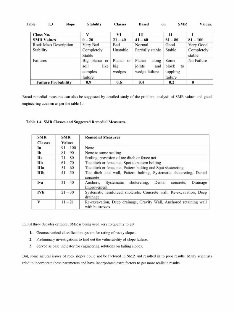
F1, defines angular difference between orientation of slop face and strike of most significant joint.
F2, refers to angle of dip of most significant joint in planar and toppling mode of failure and angle of plunge of line
created by intersection of two joint planes in case of wedge failure. (Romana, 1993),
F3,defines angular difference between inclination of slope and dip of the most significant joint.
F4, is defined as adjustment factor for the method of excavation which has been fixed empirically.
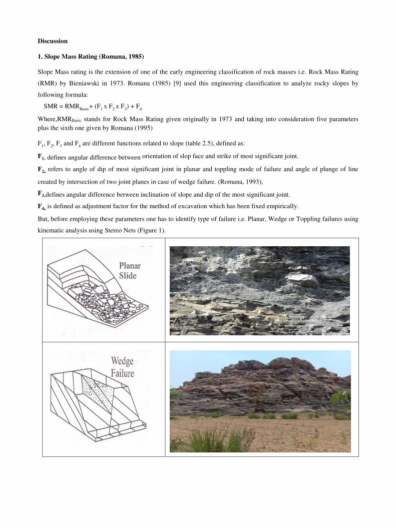
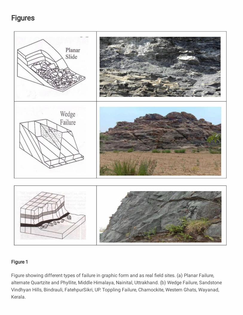
But, before employing these parameters one has to identify type of failure i.e. Planar, Wedge or Toppling failures using
kinematic analysis using Stereo Nets (Figure 1).
Page 5
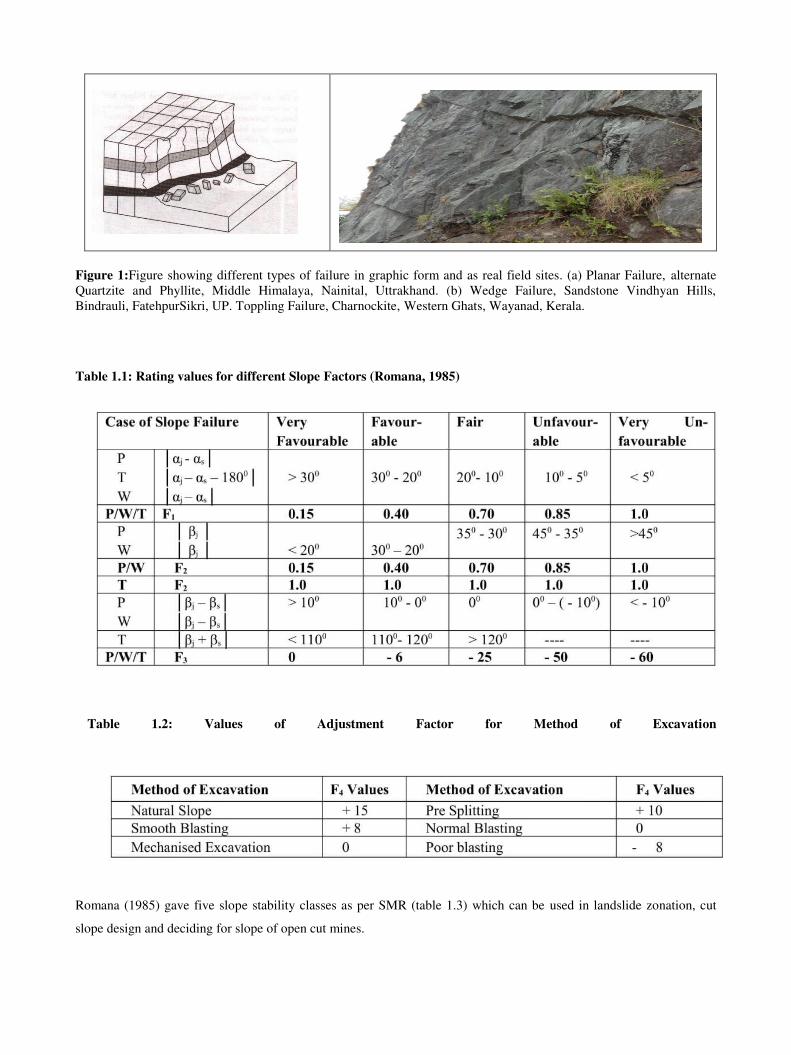
Figure 1:Figure showing different types of failure in graphic form and as real field sites. (a) Planar Failure, alternate
Quartzite and Phyllite, Middle Himalaya, Nainital, Uttrakhand. (b) Wedge Failure, Sandstone Vindhyan Hills,
Bindrauli, FatehpurSikri, UP. Toppling Failure, Charnockite, Western Ghats, Wayanad, Kerala.
Table 1.1: Rating values for different Slope Factors (Romana, 1985)
Table 1.2: Values of Adjustment Factor for Method of Excavation
Romana (1985) gave five slope stability classes as per SMR (table 1.3) which can be used in landslide zonation, cut
slope design and deciding for slope of open cut mines.
Page 6
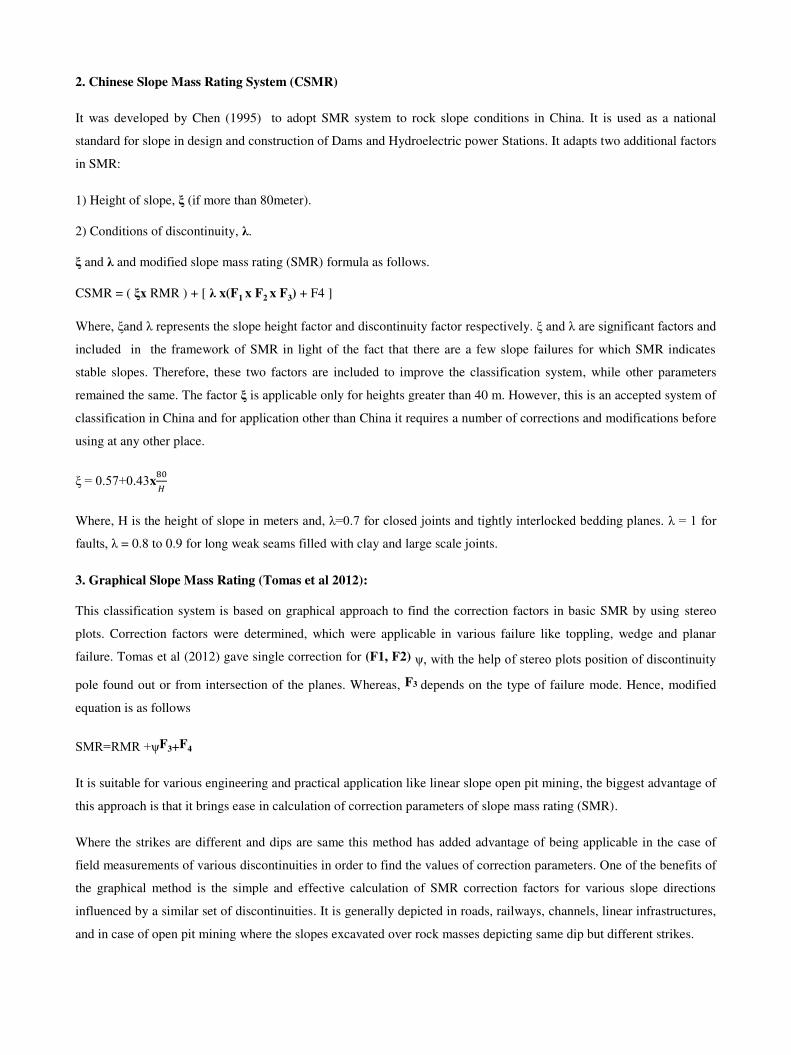
Table 1.3 Slope Stability Classes Based on SMR Values.
Broad remedial measures can also be suggested by detailed study of the problem, analysis of SMR values and good
engineering acumen as per the table 1.4
Table 1.4: SMR Classes and Suggested Remedial Measures.
In last three decades or more, SMR is being used very frequently to get:
1. Geomechanical classification system for rating of rocky slopes.
2. Preliminary investigations to find out the vulnerability of slope failure.
3. Served as base indicator for engineering solutions on failing slopes.
But, some natural issues of rock slopes could not be factored in SMR and resulted in to poor results. Many scientists
tried to incorporate these parameters and have incorporated extra factors to get more realistic results.
Page 7
2. Chinese Slope Mass Rating System (CSMR)
It was developed by Chen (1995) to adopt SMR system to rock slope conditions in China. It is used as a national
standard for slope in design and construction of Dams and Hydroelectric power Stations. It adapts two additional factors
in SMR:
1) Height of slope, ξ (if more than 80meter).
2) Conditions of discontinuity, λ.
ξ and λ and modified slope mass rating (SMR) formula as follows.
CSMR = ( ξx RMR ) + [ λ x(F1 x F2 x F3) + F4 ]
Where, ξand λ represents the slope height factor and discontinuity factor respectively. ξ and λ are significant factors and
included in the framework of SMR in light of the fact that there are a few slope failures for which SMR indicates
stable slopes. Therefore, these two factors are included to improve the classification system, while other parameters
remained the same. The factor ξ is applicable only for heights greater than 40 m. However, this is an accepted system of
classification in China and for application other than China it requires a number of corrections and modifications before
using at any other place.
ξ = 0.57+0.43x80𝐻
Where, H is the height of slope in meters and, λ=0.7 for closed joints and tightly interlocked bedding planes. λ = 1 for
faults, λ = 0.8 to 0.9 for long weak seams filled with clay and large scale joints.
3. Graphical Slope Mass Rating (Tomas et al 2012):
This classification system is based on graphical approach to find the correction factors in basic SMR by using stereo
plots. Correction factors were determined, which were applicable in various failure like toppling, wedge and planar
failure. Tomas et al (2012) gave single correction for (F1, F2) ψ, with the help of stereo plots position of discontinuity
pole found out or from intersection of the planes. Whereas, F3 depends on the type of failure mode. Hence, modified
equation is as follows
SMR=RMR +ψF3+F4
It is suitable for various engineering and practical application like linear slope open pit mining, the biggest advantage of
this approach is that it brings ease in calculation of correction parameters of slope mass rating (SMR).
Where the strikes are different and dips are same this method has added advantage of being applicable in the case of
field measurements of various discontinuities in order to find the values of correction parameters. One of the benefits of
the graphical method is the simple and effective calculation of SMR correction factors for various slope directions
influenced by a similar set of discontinuities. It is generally depicted in roads, railways, channels, linear infrastructures,
and in case of open pit mining where the slopes excavated over rock masses depicting same dip but different strikes.
Page 8
4. Continuous Slope Mass Rating (Co SMR)
Romana (1985 suggested), for F1, F2, F3 and F4in SMR = RMRB + (F1 x F2 x F3) + F4, are discrete and relies more on
judgment of the explorer and investigator Since it requires a lot of experience in assigning the rating based on one’s
experience. Tomas et al., (2007) [16] proposed a continuous function for F1, F2, F3 and F4 which best suits the discrete
values. Following are the equations for the continuous functions:
Where, A is difference between slope strike and plunge direction of angle of intersection for wedge failure and
parallelism between slope strike and joint strike for planar and toppling failures. B is plunge of angle of intersection in
wedge failure and dip of joint in planar failure. C is difference between angle of slope and dip of joint for planar failure,
in case of toppling failure, difference between angle of slope and plunge of line of intersection, for wedge failure,
addition of slope angle and dip of joint.
5. Landslide Hazard Zonation(IS:14496 Part II)
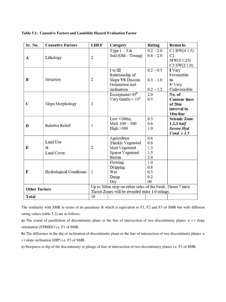
The Bureau of Indian Standard has given this code IS 14496 Part II, 1985, [5] for landslide hazard mapping based on
ten causative factors with each factor given landslide hazard evaluation factor (LHEF) as 1 or 2, totaling 10 maximum
points. (table 5.1). The area to be mapped for landslide hazard zonation is to be divided into different smaller regions
using maps of 1: 50,000 to 1: 25,000 for macro zonation.
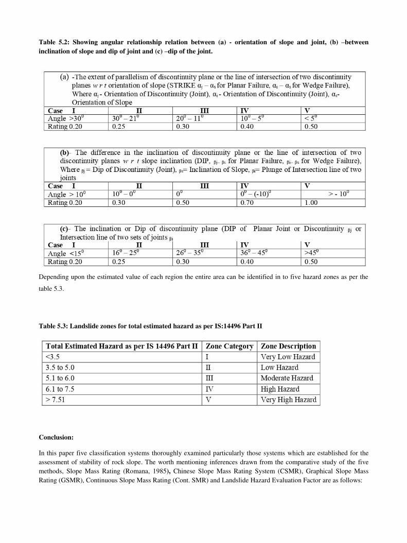
It has direct similarity with SMR in terms of its parameter B which is equivalent to F1, F2 and F3 of SMR (table 5.2).
Page 9
Table 5.1: Causative Factors and Landslide Hazard Evaluation Factor
The similarity with SMR in terms of its parameter B which is equivalent to F1, F2 and F3 of SMR but with different
rating values (table 5.2) are as follows:
a) The extent of parallelism of discontinuity plane or the line of intersection of two discontinuity planes w r t slope
orientation (STRIKE) i.e. F1 of SMR.
b) The difference in the dip or inclination of discontinuity plane or the line of intersection of two discontinuity planes w
r t slope inclination (DIP) i.e. F3 of SMR.
c) Steepness or dip of the discontinuity or plunge of line of intersection of two discontinuity planes i.e. F2 of SMR
Page 10
Table 5.2: Showing angular relationship relation between (a) - orientation of slope and joint, (b) –between
inclination of slope and dip of joint and (c) –dip of the joint.
Depending upon the estimated value of each region the entire area can be identified in to five hazard zones as per the
table 5.3.
Table 5.3: Landslide zones for total estimated hazard as per IS:14496 Part II
Conclusion:
In this paper five classification systems thoroughly examined particularly those systems which are established for the
assessment of stability of rock slope. The worth mentioning inferences drawn from the comparative study of the five
methods, Slope Mass Rating (Romana, 1985), Chinese Slope Mass Rating System (CSMR), Graphical Slope Mass
Rating (GSMR), Continuous Slope Mass Rating (Cont. SMR) and Landslide Hazard Evaluation Factor are as follows:
Page 11
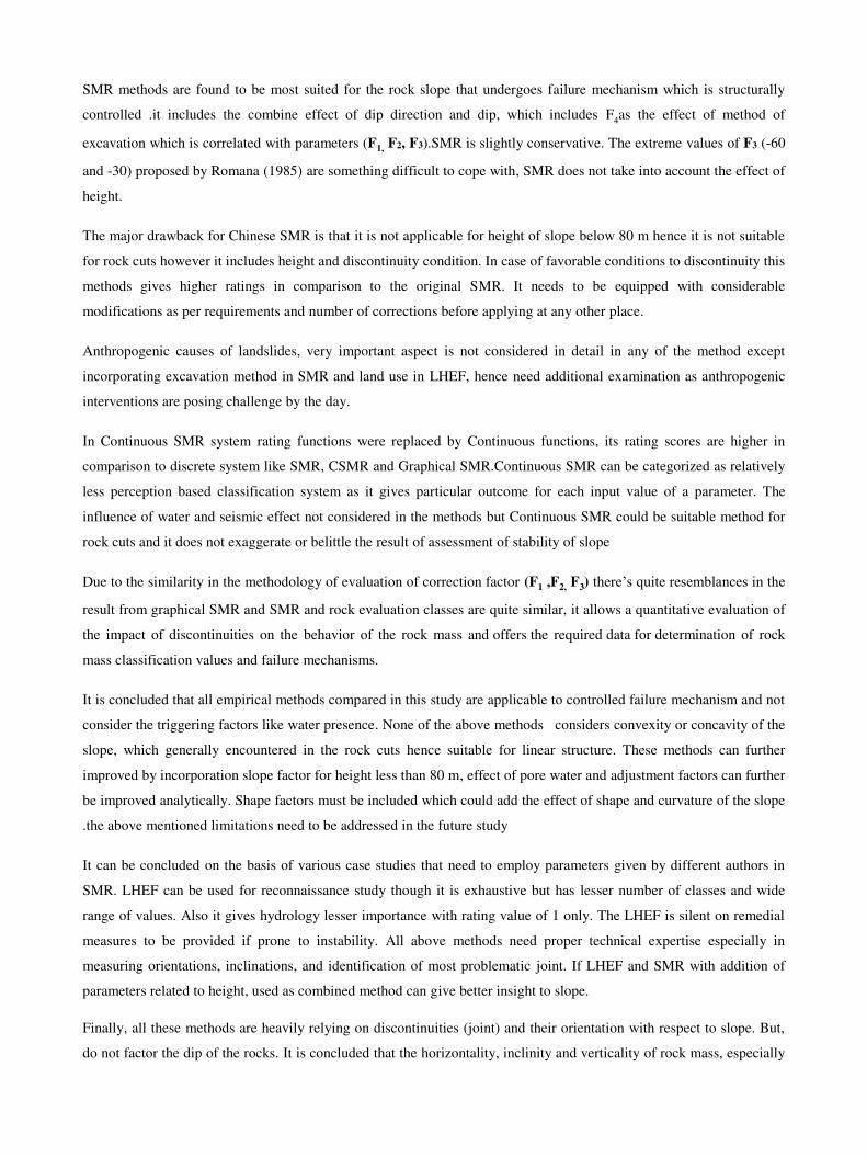
SMR methods are found to be most suited for the rock slope that undergoes failure mechanism which is structurally
controlled .it includes the combine effect of dip direction and dip, which includes F4as the effect of method of
excavation which is correlated with parameters (F1, F2, F3).SMR is slightly conservative. The extreme values of F3 (-60
and -30) proposed by Romana (1985) are something difficult to cope with, SMR does not take into account the effect of
height.
The major drawback for Chinese SMR is that it is not applicable for height of slope below 80 m hence it is not suitable
for rock cuts however it includes height and discontinuity condition. In case of favorable conditions to discontinuity this
methods gives higher ratings in comparison to the original SMR. It needs to be equipped with considerable
modifications as per requirements and number of corrections before applying at any other place.
Anthropogenic causes of landslides, very important aspect is not considered in detail in any of the method except
incorporating excavation method in SMR and land use in LHEF, hence need additional examination as anthropogenic
interventions are posing challenge by the day.
In Continuous SMR system rating functions were replaced by Continuous functions, its rating scores are higher in
comparison to discrete system like SMR, CSMR and Graphical SMR.Continuous SMR can be categorized as relatively
less perception based classification system as it gives particular outcome for each input value of a parameter. The
influence of water and seismic effect not considered in the methods but Continuous SMR could be suitable method for
rock cuts and it does not exaggerate or belittle the result of assessment of stability of slope
Due to the similarity in the methodology of evaluation of correction factor (F1 ,F2, F3) there’s quite resemblances in the
result from graphical SMR and SMR and rock evaluation classes are quite similar, it allows a quantitative evaluation of
the impact of discontinuities on the behavior of the rock mass and offers the required data for determination of rock
mass classification values and failure mechanisms.
It is concluded that all empirical methods compared in this study are applicable to controlled failure mechanism and not
consider the triggering factors like water presence. None of the above methods considers convexity or concavity of the
slope, which generally encountered in the rock cuts hence suitable for linear structure. These methods can further
improved by incorporation slope factor for height less than 80 m, effect of pore water and adjustment factors can further
be improved analytically. Shape factors must be included which could add the effect of shape and curvature of the slope
.the above mentioned limitations need to be addressed in the future study
It can be concluded on the basis of various case studies that need to employ parameters given by different authors in
SMR. LHEF can be used for reconnaissance study though it is exhaustive but has lesser number of classes and wide
range of values. Also it gives hydrology lesser importance with rating value of 1 only. The LHEF is silent on remedial
measures to be provided if prone to instability. All above methods need proper technical expertise especially in
measuring orientations, inclinations, and identification of most problematic joint. If LHEF and SMR with addition of
parameters related to height, used as combined method can give better insight to slope.
Finally, all these methods are heavily relying on discontinuities (joint) and their orientation with respect to slope. But,
do not factor the dip of the rocks. It is concluded that the horizontality, inclinity and verticality of rock mass, especially
Page 12
in layered rocks and their orientation with slope should also be taken into consideration. Also presence of “Shear
Zones” which are very common in rock masses and are venues of severe mass wasting have not been considered where
the discontinuity related parameters are overwhelmed.
Acknowledgement: The authors acknowledge the support of Deptt.of Civil Engineering and the scholarship from
AMU to the corresponding author.
References
[1].Aksoy CO Review of rock mass rating classification: historical developments, applications and restrictions. J Min Sci 44(1):51–63(2008)
[2].Bashel,Hassan,Mitri ,Application of rockmass classification system to rock slope stability assessment :A case study
,Journal of rock mechanics and geotechnical engineering 9;993-1009(2017)
[3]. Bieniawski, Z.T., Engineering Rock Mass Classification. Wiley, Chichester, 251 pp( 1989)
[4].Bieniawski, Z.T.,. Quo Vadis Rock Mass classifications. Felsbau 15, 177-178(1997)
[5].Bieniawski ZT ,Tunnel design by rock mass classifications. Technical report GL-79-19; Pennsylvania State
University, Department of Mineral Engineering University Park, Pennsylvannia. p 158(1990)
[6].Bieniawski, Z. T., Engineering Classification of Jointed Rock Masses. Trans. Afr. Inst. Civ. Engg. 15, Pp. 335 –
344, (1973).
[7].Barton, N., Lien, R. and Lunde, J., Engineering Classification of Rock Masses for the Design of Tunnel Support.,
Rock Mech. 6, Pp. 183 – 236, (1974).
[8].Chen, Zuyu ISRM-8CONGRESS-, International Society for Rock Mechanics and Rock Engineering 8th ISRM
Congress, 25-29 September, Tokyo, Japan(1995-1996)
[9].CHEN, Z.Y., WANG, X.G., YANG. J., JIA, Z.X. & WANG, Y.J., Rock slope stability analysis: principle, method,
and procedure.– Beijing: China Water Power Press (in Chinese). (2005)
[10].Duran,A &Douglas,K Experince with empirical rock slope design in: proceeding ISRM international symposium
(2000)
[11].Goodman R E Methods of geological engineering in discontinuous rocks; West Publishing, San Francisco(1976)
[12].Hoek, rock mass properties ,practical rock mass engineering www.rocscience / hoek s corner (2007)
[13].Hoek E and Bray J W , Rock slope engineering; Institution of Mining and Metallurgy, London(1981)
[14].Harrison JP, Hudson JA ,Engineering rock mechanics: illustrative worked examples. Elsevier Science, Oxford, p
530(2000)
Page 13
[15].Hack. H.R., An evaluation of Slope Stability Classification, in: Dinis da Gama, C. and Ribeira e Sousa, L. (Eds.),
Keynote Lecture, Proc. ISRM EUROCK’2002, Publ. SociedadePortuguesa de Geotecnia, Lisboa, Portugal. pp. 3 –
32.(2002).
[16].Landslide Hazard Evaluation Factor, Bureau of Indian Standard Code (IS:14496 Part II), (1995).
[17].Kundu, Jagadish; Kripamoy Sarkar, Ashutosh Tripathy,* and T N Singh; Qualitative stability assessment of cut
slopes along the National Highway-05 around Jhakri area, Himachal Pradesh, India, J. Earth Syst. Sci. 126:112(2017)
[18.]LI, X.Z., KONG, J.M. & WANG, C.: Modification of rock slope stability classification systems by continuous
functions and its application.– Chinese Journal of Rock Mechanics and Engineering, 29/Supp.1, 3439–3446 (in
Chinese). (2010)
[19].Milne D, Hadjigeorgiou J, Pakalnis R Rock mass characterization for underground hard rock mines. Tunn Undergr
Space Technol 13(4):383–391(1998)
[20]Matherson G D , The collection and use of field discontinuity data in rock slope design; Quart. J. Eng. Geol. 22 19–30 (1988)
[21].National Disaster Management Authority Guidelines—Management of Landslides and Snow Avalanches, 2009.Pp
1 - 144 A publication of the National Disaster Management Authority, Government of India.(2009).
[22].Pantelidis, L., Rock slope stability assessment through rock mass classification systems. ,i46:315–325(2009)
[23].Pantelidis, L., An alternative rock mass classification system for rock slopes. Bull.Engg. Geol. Environ. 69:29–39(2010)
[24].Romana M New adjustment ratings for application of Bieniawski classification to slopes. In: International symposium on the role of rock mechanics ISRM, Zacatecas, pp 49–53(1985)
[25]. Romana M, Seron JB, Montalar E (2001) La Clasificaciongeomecanica SMR. Aplicacionexperenciasvalidacion. In: V SimposioNacional de LaderasInestables, Madrid, pp 575–600 (2001)
[26]. Romana M DMR (dam mass rating) an adaptation of RMR geomechanics classification for use in dams
foundations. In: ISRM—technology roadmap for rock mechanics, South African Institute of Mining and Metallurgy
(2003)
[27].Romana M, Seron JB, Montalar E, SMR Geomechanics classification: application, experience and validation.In:
ISRM—technology road map for rock mechanics, South African Institute of Mining and Metallurgy(2003).
[28].Romana, M. Serón, J.B., Jordá, L., Vélez, M.I. La clasificación geomecánica SMR para
taludes: Estado actual, aplicación y experiencia internacional, in: Corominas, J., Alonso, E., (2005).
[29].Romana M, Toma ´s R, Sero ´n JB Slope mass rating (SMR) geomechanics classification: thirty years review. In: ISRM Congress 2015 proceedings—international symposium on rock mechanics, Quebec, Canada, ISBN: 978-1-
926872-25-4, p 10(2015)
[30].Romana, M. A geomechanical classification for slopes: Slope Mass Rating, in: Hudson,
J.A. (Ed.), Comprehesive Rock Engineering, Pergamon Press, Oxford, pp. 575–599. (1993)
[31].Romana M ,The geomechanics classification SMR for slope correction. In: Proceedings of the 8th international ISRM congress, pp 1085–1092(1995)
Page 14
[32].Siddique T, Alam MM, Mondal MEA, Vishal V ,Slope mass rating and kinematic analysis of slopes along national
highway58, near Jonk, Rishikesh, India. J Rock Mech and GeotechEng7:600–606(2015).
[33].S.P. Pradhan, T. Siddique ; stability assessment of landslide prone road cuts rock slope in Himalaya terrain ,A
finite element based approach Journal of Rock Mechanics and Geotechnical Engineering ;12: 59-73(2020)
[34].SHI, Y.C., WANG, Z.W., WAN, G.R., WANG, Z.Y., CHEN, Q.Y. & TANG, S.C. : Study of mountain highway
slope mass rating.– Chinese Journal of Rock Mechanics Engineering, 24/6, 939–944. (2005)
[35].Terzaghi, K., Rock Defects and Loads on Tunnel Support. Rock Tunneling with Steel Supports.Edt.: Proctor and
White, Commercial Shearing Company, Pp 15-99 (1946).
[36].Taherniya MH, Mohammadi M, Ajalloeian R Assessment of slope instability and risk analysis of road cut slopes in
Lashotor Pass, Iran. J Geol Res 2014:1–12(2014)
[37].Toma ´s R, Delgado J, Sero ´n JB Modification of slope mass rating (SMR) by continuous functions.Int J Rock
Mech Min Sci 44:1062–1069 (2007)
[38].Tomás, R., Cuenca, A., Cano, M., García-Barba, J., A graphical approach for Slope Mass Rating
(SMR).Engineering Geology, 124, 67-76, (2012).
[39].WU, D.B. & XU, W.Y. GSMR method for determining rock slope mechanical parameters.– Rock and Soil
Mechanics, 26/9, 1421–1426(2005)
Page 15
Figures
Figure 1
Figure showing different types of failure in graphic form and as real �eld sites. (a) Planar Failure,alternate Quartzite and Phyllite, Middle Himalaya, Nainital, Uttrakhand. (b) Wedge Failure, SandstoneVindhyan Hills, Bindrauli, FatehpurSikri, UP. Toppling Failure, Charnockite, Western Ghats, Wayanad,Kerala.