Page 1
Cisco Systems, Inc.All contents are Copyright © 1992–2002 Cisco Systems, Inc. All rights reserved. Important Notices and Privacy Statement.
Page 1 of 42
White Paper
Comparison of the Cisco Catalyst and Cisco IOS OperatingSystems for the Cisco Catalyst 6500 Series Switch
Version 2
Purpose
This white paper compares the two
software options for the Cisco Catalyst®
6500 Series: the Catalyst Operating System
(CatOS) and the Cisco IOS® Software. It
discusses the software architecture,
operation, and configuration for CatOS and
the Cisco IOS Software (also known as
“Native” model) on Cisco Catalyst 6500
Series switches. To that end, this paper is
also an overview of the Cisco IOS Software
on the Supervisor Engine for the Cisco
Catalyst 6500 Series.
This paper does not cover all the features
available in the Cisco Catalyst 6500
software. It provides a review of the more
frequently used Cisco Catalyst 6500
features for both software models1.
Additionally, this paper is a migration guide
for readers who are familiar with CatOS
and are considering using the Cisco IOS
Software with their Cisco Catalyst 6500
switches. This is the second version of
this document.
1. All features and support references are to CiscoCatOS Version 7.3.1 release and Cisco IOS SoftwareRelease 12.1(11b)EX1; there may have been caveats orgeneral lack of support in previous releases that thisdocument does not account for; refer to the release notesfor specific details.
Introduction
The proliferation of intranet and
Internet-based applications is driving new
business models such as e-commerce and
e-learning. Delivered via intelligent Internet
Protocol (IP) services, these applications are
transforming corporate-intranet and service
provider infrastructures into competitive
tools which offer lower business costs,
faster information flow, and scalable
services. In its market leadership position,
Cisco Systems offers software options that
enable services throughout a network
infrastructure and give customers a choice
for their specific networking needs and
requirements. The Cisco Catalyst 6500
Series Switch provides two software
operating modes:
• Cisco CatOS on the Cisco Catalyst
6500 Series with optional Cisco IOS
Software on the Multilayer Switching
Feature Card (MSFC) provides Layer
2/3/4 functionality for the Cisco
Catalyst 6500 by integrating two
operating systems. A switch running
CatOS only on the Supervisor Engine is
a Layer 2 forwarding device with Layer
2/3/4 functionality for Quality of
Page 2
Cisco Systems, Inc.All contents are Copyright © 1992–2002 Cisco Systems, Inc. All rights reserved. Important Notices and Privacy Statement.
Page 2 of 42
Service (QoS), security, multicast, and network management of the Policy Feature Card (PFC), but does not have
any routing capabilities. Layer 3 routing functionality is provided via a Cisco IOS Software image on the optional
MSFC routing engine. In this paper, the combination of CatOS on the Supervisor Engine and Cisco IOS Software
on the MSFC is referred to as the “hybrid” OS, meaning that two operating systems work together to provide
complete Layer 2/3/4 system functionality.
The hybrid model operates based on two operating images, two configurations, and two command lines; one of
each for CatOS and the Cisco IOS Software. The default operation of CatOS is as a switch (all ports bridging in
VLAN 1), but can be configured to operate as a router.
This operating model, as a Layer 2 forwarding device, targets wiring closet or access layer services with protocols
such as IEEE 802.1x, inline power, and voice virtual LAN (VLAN) identification. With the optional MSFC, the
chassis is suitable for distribution or core layers of a network.
• Cisco IOS Software for the Supervisor Engine on the Cisco Catalyst 6500 Series provides a single Cisco IOS
image, configuration, and command line to support all Layer 2, 3, and 4 functionality on the switch. Cisco IOS
has historically been a Layer 3 operating system on routing platforms; Cisco IOS on the supervisor of a Cisco
Catalyst 6500 has expanded these capabilities to include true Layer 2 functionality as well. Cisco IOS requires a
MSFC daughter card be present on the Supervisor Engine. In this paper, the term “Cisco IOS” refers to the Cisco
IOS Software on the Supervisor Engine of the Cisco Catalyst 6500 Series.
The default operation of the Cisco IOS Software is as a router (all ports are routed and shutdown), but can be
configured to operate as a switch.
The Cisco IOS operating mode targets service provider and enterprise data center backbones and distribution
layer services. Cisco IOS Software combines the switching features of the Cisco Catalyst 6500 Series Switch with
routing features of Cisco IOS Software to create a single, integrated operating system that performs all switching
and routing functionality. A Cisco IOS system has the capability to scale the throughput and bandwidth of a Cisco
Catalyst 6500 Series to 210 Mpps and 256 Gbps, respectively. This provides operational ease of use by allowing
customers to deploy a single image across their Cisco Catalyst 6500 Series product line.
Both operating models can exist simultaneously in a network environment to satisfy varying requirements. One
model is recommended over another based solely on feature support, because both models are not at 100 percent
feature parity. One model is not a replacement for another, because both will continue feature development.
Figure 1 illustrates the two operating systems in a typical network architecture.
Page 3
Cisco Systems, Inc.All contents are Copyright © 1992–2002 Cisco Systems, Inc. All rights reserved. Important Notices and Privacy Statement.
Page 3 of 42
Figure 1
Cisco IOS Software and Cisco Catalyst OS Positioning
Architecture Comparison
The Cisco Catalyst 6500 offers a high-performance blend of Layer 2/3/4+ technology. Independent of the software
model chosen, the forwarding intelligence of the system is performed in the following hardware: the Supervisor (with
switch processor) baseboard, the PFC daughter card, and the MSFC (route processor) daughter card (Figure 2).
Distribution Layer
Catalyst OS/Cisco IOS
Cisco IOS
Core
Cisco IOS
Cisco IOS
WAN
ISP
ISP
Server Farm/Data Center
Access Layer Catalyst OS
WAN Edge
E-Commerce/Data Center
Server Server Server
Laptop Laptop Laptop
CiscoCatalyst 6500with MSFC
CiscoCatalyst6500
CiscoCallManager
Server Server Server
Cisco IOS
Page 4
Cisco Systems, Inc.All contents are Copyright © 1992–2002 Cisco Systems, Inc. All rights reserved. Important Notices and Privacy Statement.
Page 4 of 42
Figure 2
Cisco Catalyst 6500 Processors
Switch Processor Functions
The Switch Processor runs a 250-Mhz R7000 CPU (Supervisor 2) and controls all chassis operations. This includes
the detection of Online Insertion and Removal (OIR) events, power management, environmental management, and
redundancy management. It also handles the download of the appropriate line card firmware to each line card. The
Switch Processor handles basic port management (setting of port configuration, detection of link state, etc.) along
with other Layer 2 functions such as Spanning Tree, VLAN Trunking Protocol (VTP), Interior Gateway Multicast
Protocol (IGMP) snooping, and Dynamic Trunking Protocol (DTP). Finally, the SP provides console connection
during initial system boot.
Route Processor Functions
The Route Processor (RP) runs a 300-Mhz R7000 CPU (MSFC2) and provides Layer 3 functions such as routing and
Cisco Express Forwarding table creation. Cisco Express Forwarding is the default Layer 3 forwarding mechanism.
Although the actual packet forwarding takes place in the hardware, the RP’s creation of the Cisco Express
Forwarding and adjacency tables are critical. Along with the Policy Feature Card (PFC), the RP provides QoS and
security functionality as well. Other functions that run on the RP include IP address resolution (ARP) and routing
table maintenance.
Policy Feature Card (PFC)
The PFC is the application-specific integrated circuit (ASIC) forwarding complex for the system. The PFC performs
the hardware-based features and services at a high performance level (tens of millions of packets per second).
Features such as Layer 2 bridging, Layer 3 routing, access control, QoS marking and policing, NetFlow statistics,
and multicast are implemented in the hardware of the PFC. The PFC relies on the SP and RP control plane functions
for managing the hardware functionality.
Software Implementation
The key to Cisco IOS mode is that both CPUs (SP and RP) run the full Cisco IOS Software. There is no hidden
Catalyst software running on the box and the executable images used by both CPUs run the complete IOS kernel.
Both processors on Cisco IOS Software are used to improve overall system performance. Should the MSFC fail, all
Layer 2/3/4 functionality is lost. The RP provides the system console connection once the system is fully operational.
In contrast, CatOS operates on the SP and the PFC to provide Layer 2 forwarding and Layer 3/4 services. Should the
user require Layer 3 forwarding/routing capabilities, the MSFC daughter card must be present and runs Cisco IOS
Software (as part of the hybrid OS). Thus, should the MSFC fail in this model, Layer 2 functionality is not affected
and remains operational.
MSFC RouteProcessor (RP)
Policy Feature Card(PFC)
Catalyst Supervisor Switch Processor (SP)
Page 5
Cisco Systems, Inc.All contents are Copyright © 1992–2002 Cisco Systems, Inc. All rights reserved. Important Notices and Privacy Statement.
Page 5 of 42
Software Feature Support
The two software models of the Cisco Catalyst 6500 Series are not at complete feature parity. Because of this, the
following table presents the CatOS and Cisco IOS Software support for some of the more commonly used protocols.
However, note that many features in the Cisco IOS Software are not platform specific (like the OSPF, BGP, or PIM
protocols). In these cases, the Cisco IOS features in the hybrid OS are identical to those features in the Cisco IOS
Software. Additionally, Cisco IOS Software supports most of the Layer 2 CatOS functionality.
Table 1 lists commonly used software features available in Cisco CatOS Version 7.3.1 and Cisco IOS Software
Release 12.1(11b)EX.
Table 1 Software Comparison
Software Feature CatOS Cisco IOS
VLAN ranges: 1000 VLANs (Layer 3 VLAN interfaces) x x
Inter VLAN routing x x
4096 Layer 2 VLANs x x
Private VLANs x x
Dynamic VLANs x
Trunking: IEEE 802.1q, ISL x x
DTP, VTP x x
IEEE 802.1q tunneling x x
Layer 2 Protocol tunneling x x
Spanning Tree: PortFast, UplinkFast, BackboneFast, BPDU Guard x x
IEEE 802.1s and 802.1w x x
Jumbo frames x x
EtherChannel, Port Aggregation Protocol (PAgP) x x
EtherChannel, IEEE 802.3ad (LACP) x x
Remote Span (RSPAN) x
Multicast Services: PIM, IGMP snooping, RGMP x x
QoS Marking, Policing, Scheduling x x
QoS ACLs x x
Routing ACLs x x
VLAN ACLs x x
Cisco IOS Server Load Balancing x
Broadcast suppression x x
Protocol filtering, Cisco IOS support on Supervisor Engine 1A systems only x x
Port security x
Page 6
Cisco Systems, Inc.All contents are Copyright © 1992–2002 Cisco Systems, Inc. All rights reserved. Important Notices and Privacy Statement.
Page 6 of 42
Hardware and Line Card Support
Table 2 is a matrix of Cisco Catalyst 6500 Series line cards with operating system support.
IEEE 802.1x x
Cisco Discovery Protocol x x
NetFlow Data Export (NDE) x x
Unidirectional Link Detection (UDLD) x x
Voice VLAN ID (VVID) and inline power for Cisco IP Phones x
Supervisor redundancy and failover x x
Stateful Supervisor Switchover x
Multiprotocol Label Switching (MPLS), EoMPLS, MPLS VPN x
Distributed Cisco Express Forwarding (dCEF) x
Table 2 Hardware Modules
Chassis and Supervisors CatOS Cisco IOS
WS-C6513, WS-C6509, WS-C6509-NEB, WS-C6009, WS-C6506, WS-C6006,OSR-7609-AC/DC, CISCO7603, CISCO7606, WS-C6509
x x
WS-X6K-S2U-MSFC2 x x
WS-X6K-S2-MSFC2 x x
WS-X6K-S2-PFC2 x
WS-X6K-S1A-MSFC2 x x
WS-X6K-SUP1A-MSFC x x
WS-X6K-SUP1A-PFC x
WS-X6K-SUP1A-2GE x
WS-X6K-SUP1-2GE x
Switching Fabrics x x
WS-C6500-SFM x x
WS-X6500-SFM 2 x x
Ethernet Line Cards x x
WS-F6K-DFC x
WS-X6816-GBIC x
WS-X6501-10GEX4 x x
Table 1 Software Comparison
Software Feature CatOS Cisco IOS
Page 7
Cisco Systems, Inc.All contents are Copyright © 1992–2002 Cisco Systems, Inc. All rights reserved. Important Notices and Privacy Statement.
Page 7 of 42
WS-X6502-10GE x x
WS-G6483 x x
WS-G6488 x x
WS-X6516-GBIC x x
WS-X6516-GE-TX x x
WS-X6416-GBIC x x
WS-X6416-GE-MT x x
WS-X6316-GE-TX x x
WS-X6408A-GBIC x x
WS-X6408-GBIC x x
WS-X6524-100FX-MM x x
WS-X6324-100FX-SM/MM x x
WS-X6224-100FX-MT x x
WS-X6548-RJ-21 x x
WS-X6548-RJ-45 x x
WS-X6348-RJ-21/V x x
WS-X6348-RJ-45/V x x
WS-X6148-RJ-45V x x
WS-X6148-RJ21V x x
WS-X6248-RJ-45 x x
WS-X6248A-TEL x x
WS-X6248-TEL x x
WS-X6024-10FL-MT x x
Voice Line Cards
WS-X6624-FXS x
WS-X6608-T1/E1 x
Services Modules
WS-X6381-IDS x x
WS-X6380-NAM x x
WS-X6066-SLB-APC x
WS-SVC-CSG-1 x
Table 2 Hardware Modules
Chassis and Supervisors CatOS Cisco IOS
Page 8
Cisco Systems, Inc.All contents are Copyright © 1992–2002 Cisco Systems, Inc. All rights reserved. Important Notices and Privacy Statement.
Page 8 of 42
As Table 2 shows, the majority of line cards are supported in both CatOS and Cisco IOS Software. For specific
software information on each line card, refer to the release notes at:
http://www.cisco.com/univercd/cc/td/doc/product/lan/cat6000/relnotes/index.htm.
Memory Requirements
The default memory requirements are the same for both the Cisco IOS Software and the CatOS software. The
Supervisor Engine 1a ships with a default of 128 MB DRAM and 16 MB bootflash. The Supervisor Engine 2 ships
with a default of 128 MB DRAM (upgradable to 512 MB) and 32 MB bootflash. The MSFC2 ships with 128 MB
DRAM and can be upgraded to 512 MB. The WS-X6K-S2U-MSFC2 is an orderable part number for 256 MB of
DRAM on the Supervisor Engine 2 as well as 256 MB DRAM on the MSFC2.
Because the Cisco IOS Software images are combined Layer 2 and 3 images, they are larger than CatOS images.
Today’s Cisco IOS images are greater than 20 MB in some cases. For customer’s who want to store more than one
Cisco IOS Software image for a system, the MEM-C6K-ATA-1-64M flash card, which allows up to 64 MB of storage,
is available.
For routing table capacity, the Cisco IOS Software has specific memory guidelines, which are documented in the
release notes. Refer to the Cisco Catalyst 6500 Series release notes for these recommendations.
WS-SVC-NAM-1 x
WS-SVC-NAM-2 x
Miscellaneous Modules
WS-X6101-OC12-SMF/MMF x
WS-X6302-MSM x
WAN Modules
WS-X6182-2PA x x
OSM-4GE-WAN-GBIC x x
OSM-2OC12-POS-MM/SI/SL x x
OSM-4OC12-POS-MM/SI/SL x x
OSM-4OC3-POS-SI x x
OSM-8OC3-POS-MM/SI/SL x x
OSM-16OC3-POS-MM/SI/SL x x
OSM-1OC48-POS-SS/SI/SL x x
OSM-1CHOC48/T3-SS/SI x
OSM-4CHOC12/T3-MM/SI x
OSM-2OC12-ATM-MM/SI x
Table 2 Hardware Modules
Chassis and Supervisors CatOS Cisco IOS
Page 9
Cisco Systems, Inc.All contents are Copyright © 1992–2002 Cisco Systems, Inc. All rights reserved. Important Notices and Privacy Statement.
Page 9 of 42
Operational Comparison
Image Management
There are different image naming conventions for systems with hybrid operating systems and for systems with Cisco
IOS Software on the Supervisor Engine. Please make sure that the correct image is chosen for given hardware. The
following sections describe the different image filenames for CatOS and Cisco IOS Software.
Operating System Files for the Hybrid OS
In the hybrid model, two separate image files are managed by the two different operating systems. The CatOS images
are stored on the Supervisor bootflash or PCMCIA flash card. The Cisco IOS image for the MSFC is stored on the
MSFC bootflash. The images can be moved between the active and standby supervisors using the copy command.
Images can be uploaded to the switch via the TFTP application. Cisco Catalyst 6500 systems that run hybrid use the
image names listed in Table 3.
The same MSFC boot helper image (c6msfc-boot) is used for the hybrid OS and Cisco IOS Software. It is stored as
the first file on the MSFC bootflash. The boot helper image is a limited function system image that has network
interface code and end-host protocol code.
Note: The boot helper must never be erased on the MSFC(1) and should be the first image on the MSFC bootflash.
The MSFC2 hardware does not require the boot image as it has more sophisticated ROMMON2 functionality;
however, keeping a boot image in the MSFC bootflash is still a good practice for last resort scenarios.
Operating System Files for Cisco IOS Software
Cisco IOS Software requires the single image be present on a device local to the Supervisor because it is a bundled
image for two processors and the SP boots first. The image can reside either on the Supervisor bootflash
(sup-bootflash:) or the flash card (slot0: or disk0:); it cannot reside on the MSFC bootflash. Cisco IOS system files
start with ‘c6supxy’ where x is the supervisor model number and y is the MSFC model number:
Table 3 Hybrid OS Image Names
Image File Description
cat6000-supx CatOS image for Supervisor Engines where x is Sup1 or Sup2.
Stored on the Supervisor bootflash or slot0.
c6msfcx-boot-mz Layer 3 boot image where x is MSFC or MSFC2. Stored on the MSFCx bootflash: only.This image is required for running Cisco IOS Software on MSFC, recommended onMSFC2.
c6msfc-is-mz
c6msfc2-is-mz
Layer 3 image for the MSFC or MSFC2; works with the CatOS image on the SupervisorEngine. Stored on the MSFC bootflash: or sup-slot0:
2. ROMMON is the low-level software used for fundamental hardware operation before CatOS or Cisco IOS Software take control of the system.
Page 10
Cisco Systems, Inc.All contents are Copyright © 1992–2002 Cisco Systems, Inc. All rights reserved. Important Notices and Privacy Statement.
Page 10 of 42
In Cisco IOS Software, the MSFC(1) does require that the Cisco IOS boot image (c6msfc-boot-mz) is stored in the
MSFC bootflash.
Note: Flash card formats vary between CatOS and Cisco IOS Software thus flash cards must be formatted when
switching between operating system models.
In Cisco IOS Software, the storage device on the active supervisor are as follows:
New images can be copied into the standby supervisor: flash card, RP bootflash: or SP bootflash: from active
supervisor. The standby storage devices are:
The following is an example of the command you use to copy from active supervisor flash card to standby
supervisor flash:
Table 4 Cisco Hybrid OS Image Names
Image File Description
C6sup11 Bundled Layer 2–4 image for Supervisor 1, MSFC 1
C6sup12 Bundled Layer 2–4 image for Supervisor 1, MSFC 2
C6sup22 Bundled Layer 2–4 image for Supervisor 2, MSFC 2
slot0: Active Supervisor Linear Flash Card
disk0: Active Supervisor ATA Flash Card
sup-bootflash: Active Supervisor 16 MB or 32 MB onboard flash
bootflash: Active MSFC 16 MB MSFC onboard flash
slaveslot0: Standby Supervisor Flash Card
slavesup-bootflash: Standby Supervisor 16 MB or 32 MB onboard flash
slavebootflash: Standby MSFC 16 MB onboard flash
IOS# copy slot0:c6sup11-jsv-mz.121-5a.E1 slavesup-bootflash:
Destination filename [c6sup11-jsv-mz.121-5a.E1]?
Page 11
Cisco Systems, Inc.All contents are Copyright © 1992–2002 Cisco Systems, Inc. All rights reserved. Important Notices and Privacy Statement.
Page 11 of 42
Determining the Current Operating System on a Cisco Catalyst 6500
The Cisco IOS command line for both the Cisco IOS portion of hybrid and Cisco IOS systems look identical. To
determine what operating system is running on the switch, you can use the show version command from the Cisco
IOS command line. To access the IOS (Layer 3) functionality in hybrid OS, enter session 15 or switch console from
the command line. The console is then turned over to the MSFC, and this is where both Cisco IOS and hybrid OS
systems look identical.
Additionally, you can determine the OS on the chassis by viewing the interfaces. For example, using show ip interface
brief command on the hybrid OS shows VLANs. The same command on Cisco IOS Software displays physical
interfaces (for example, gigabitethernet 1/1) as well as VLANs interfaces.
Cisco IOS and Hybrid OS Boot Process
The boot process in both the Cisco IOS and the hybrid operating system models is automatic and transparent to the
user. In the hybrid model, the boot processes are separate for both the switch and the route processors as they each
boot independent operating systems.
In Cisco IOS Software, the two processors (the SP and RP) each load the Cisco IOS Software. Two processors
working together yield two ROMMONs and two bootflash devices. First, the SP boots to ROMMON and loads its
portion of the Cisco IOS Software. When the SP is booted, the software control is passed to the RP so that the second
processor can successfully boot. From a console perspective, the RJ-45 console port on the Supervisor Engine initially
shows information from the SP. During the boot cycle for the Cisco Catalyst 6500 with the Cisco IOS Software,
control is passed to RP CPU as shown in the following statement on the console:
From a Hybrid System
Router#show version
Cisco Internetwork Operating System Software
IOS (tm) MSFC2 Software (C6MSFC2-PSV-M) , Version 12.1(11b)E4, EARLY DEPLOYMENT R
ELEASE SOFTWARE (fc1)
From a Cisco IOS System
Router#show version
Cisco Internetwork Operating System Software
IOS (tm) c6sup2_rp Software (c6sup2_rp-PSV-M) , Version 12.1(11b)EX1, EARLY DEPL
YMENT RELEASE SOFTWARE (fc1)
Page 12
Cisco Systems, Inc.All contents are Copyright © 1992–2002 Cisco Systems, Inc. All rights reserved. Important Notices and Privacy Statement.
Page 12 of 42
After this point the Route Processor controls the system. From the software perspective, the RP acts as the primary
CPU and the SP acts as the secondary CPU. Although this is transparent to the user, all configuration commands are
entered directly through the Route Processor CPU in Cisco IOS Software. Commands entered that affect the SP
functionality are passed internally from the RP to the SP.
Unlike CatOS, net booting a Cisco IOS image from a TFTP server is not supported because the Supervisor image is
a bundled image for two processors. The runtime image location (c6sup<xy>-is-mz- <version> ) must be stored on
a device local to the SP (sup-bootflash) or the flash card (slot0:, disk0:).
Logging into the Switch Processor in Cisco IOS Software
While the command line perspective is from the RP, you can log into the Switch Processor for any Layer 2-specific
debugging. You can use the following commands for debugging and to check the Switch Processor status during
runtime. Note that all configuration for Layer 2 thru 4 components is done on the main command line:
Remote login—the remote login command (or remote login switch for the sup 2) is equivalent to the session
command in CatOS. The hostname becomes the ‘hostname—sp’. Use the exit command rather than Control-C
to exit the SP.
Remote command—If only one command’s output is needed from the SP, use a remote command <command>
(or remote command switch <command> for the Supervisor Engine 2) as seen below.
Note: There is no help facility (for example, remote command show?) when using the remote command.
System Bootstrap, Version 7.1(1 (Catalyst Supervisor ROMMON)
Copyright (c) 1994-2001 by cisco Systems, Inc.
c6k_sup2 processor with 262144 Kbytes of main memory
00:00:03: %OIR-6-CONSOLE: Changing console ownership to route processor
System Bootstrap, Version 12.1(4r)E, RELEASE SOFTWARE (fc1 (MSFC or RP ROMMON)
Copyright (c) 2000 by cisco Systems, Inc.
Cat6k-MSFC2 platform with 524288 Kbytes of main memory
IOS# remote command sw show bootvar
IOS-sp#
BOOT variable = bootflash:c6sup22-psv-mz.121-11b.EX,1
CONFIG_FILE variable =
BOOTLDR variable does not exist
Configuration register is 0x2002
IOS#
Page 13
Cisco Systems, Inc.All contents are Copyright © 1992–2002 Cisco Systems, Inc. All rights reserved. Important Notices and Privacy Statement.
Page 13 of 42
Switch Management
While the direct console cable connection is a useful way for managing a Cisco Catalyst 6500, other methods of
network-based management (such as telnet or SNMP) require a management interface with which to access the
switch. In CatOS, a single management interface, sc0, is available for the system. An IP address and VLAN are
assigned to this interface. Any IP-based management of a CatOS system is then directed to the sc0 interface address.
With the hybrid OS, the sc0 interface is used in conjunction with any Layer 3 VLAN interfaces created for routing
functionality.
In the Cisco IOS Software, the concept of a sc0 interface does not exist; however, network-based management of the
switch is still possible. For every Layer 2 VLAN that is created, there can also be a corresponding Switch Virtual
Interface (SVI, which is discussed further in the following section). Each SVI can have one or more IP addresses which
are used for accessing the device on the particular VLAN. A SNMP or telnet client can access the device via this
method. The following command displays the VLAN SVIs and the associated IP addressing for managing the system.
Switch Configuration
Configuration changes in the Catalyst software are written to NVRAM immediately after a change is made. The user
does not need to manually save configuration changes to memory. All configuration in the Catalyst OS is done via a
“set” command sequence. The set commands are done from the enabled-mode prompt. You can erase a particular
command with a clear command from the same prompt.
In contrast, Cisco IOS Software does not save configuration changes to NVRAM unless you issue the copy run start
(or write memory) command. So unless the user explicitly saves the configuration, any changes to the configuration
will be lost should the system be reloaded. All command line configuration in Cisco IOS (whether on the Supervisor
or the MSFC) is done from the configuration mode, commonly known as “config-t”. You can remove a particular
command with the no form of the original command.
Port Behavior
The following section details the differences in port behavior between the Catalyst software and the Cisco
IOS Software.
CatOS> (enable) show interface
sl0: flags=51<UP,POINTOPOINT,RUNNING>
slip 0.0.0.0 dest 0.0.0.0
sc0: flags=63<UP,BROADCAST,RUNNING>
vlan 1 inet 10.1.1.54 netmask 255.255.255.0 broadcast 10.1.1.255
IOS#show ip interface brief
Interface IP-Address OK? Method Status Protocol
Vlan1 20.1.1.1 YES manual up up
Vlan10 30.1.1.1 YES manual up down
Page 14
Cisco Systems, Inc.All contents are Copyright © 1992–2002 Cisco Systems, Inc. All rights reserved. Important Notices and Privacy Statement.
Page 14 of 42
CatOS and Cisco IOS Software on the MSFC
Before considering the Cisco IOS port concepts, a look at CatOS port concepts is used for a comparison of the two
operating systems. The hybrid model offers a very tight integration of the Layer 2/4 CatOS features with the Layer
3 Cisco IOS on the MSFC features. Layer 2 ports (such as access and trunk ports) and VLANs are configured with
the CatOS command set and Layer 3 VLAN interfaces are configured with the Cisco IOS Software on the MSFC
command set. As ports are configured in Layer 2 VLANs with CatOS (set vlan x <slot/port>), you must create a
corresponding Layer 3 SVI to enable inter-VLAN routing for the particular VLAN. You create SVIs using the
interface vlan command. In the hybrid model, the MSFC operates on these logical interfaces (interface vlan 10) rather
than physical interfaces (interface gig 1/1). Figure 3 illustrates these concepts and the associated commands to use
Layer 2 or Layer 3 functionality.
Figure 3
Port Concepts in the Hybrid Model
Cisco IOS Software
The port concepts in the Cisco IOS Software model are similar to the hybrid software model. In the Cisco IOS model,
all system configuration is done from a single command-line interface; so there is no separation between the Layer 2
and Layer 3 configuration. The Layer 2 port concepts, such as access and trunk ports and Layer 3 VLAN interfaces
(SVIs), still apply, although with somewhat different syntax. Cisco IOS Software offers the concept of a Layer 3
routed interface, as well. Table 6 provides an overview of the different Cisco IOS port and interface types, and a more
detailed description follows.
VLAN 2
Workstation
VLAN 3
Workstation
VLAN 3
Workstation Switch
VLAN 4
WorkstationAccess Ports
PhysicalPorts
Layer 2Bridging
Layer 3Routing
Trunk Port Access Port
set trunk 2/4 dot1q set vlan 4 2/5set vlan 2 2/1
SVI SVI SVI
RouteProcessorinterface vlan 2
ip address 10.2.1.1/24interface vlan 3ip address 10.3.1.1/24interface vlan 4ip address 10.4.1.1/24
Page 15
Cisco Systems, Inc.All contents are Copyright © 1992–2002 Cisco Systems, Inc. All rights reserved. Important Notices and Privacy Statement.
Page 15 of 42
Note: Although the terms interface and port are sometimes used interchangeably in this document, the Cisco IOS
command line refers to ports as interfaces, while the CatOS command line refers to them only as ports.
Figure 4 illustrates the different Cisco IOS interface types and the commands to use the Layer 2 or Layer 3
functionality.
Figure 4
Port Concepts in the Cisco IOS Model
Interface Type Purpose Sample Configuration
Routed interface Traditional IOS routing example:
each port with unique network
interface gigabitethernet 1/1
ip address 10.10.10.1 255.255.255.0
ipx network 1
Routed SVI Single routed interface for all of theswitch ports assigned to a VLAN
interface vlan 10 ip address 10.10.11.1255.255.255.0 ipx network 2
Layer 2 VLAN Single Layer 2 broadcast domain vlan 10
Access switch port interface To group Layer 2 ports into asingle VLAN
interface gigabitethernet 1/1
switchport
switchport mode access
switchport access vlan 10
Trunk switch port interface To configure Layer 2 port belonging todifferent VLANs
Interface Gigabit Ethernet 1/1
switch port
switchport trunk encap dot1q
switchport mode dynamic desirable
interface fast2/1switchportswitch mode accessswitchport access vlan 2
interface fast2/2switchportswitchport trunk encapsulation dot1qswitchport mode dynamic desirable
VLAN 2 VLAN 3 VLAN 4
Workstation SwitchAccess Switchport
PhysicalPorts
Layer 2Bridging
Layer 3Routing
Trunk Switchport Routed Interface
SVI SVI SVI
RouteProcessor
interface vlan 2ip address 10.2.1.1 255.255.255.0interface vlan 3ip address 10.3.1.1 255.255.255.0interface vlan 4ip address 10.4.1.1 255.255.255.0
interface gig3/1ip address 10.10.10.1 255.255.255.0
Switch
Page 16
Cisco Systems, Inc.All contents are Copyright © 1992–2002 Cisco Systems, Inc. All rights reserved. Important Notices and Privacy Statement.
Page 16 of 42
Cisco IOS numbers for interfaces start from 1, not 0, for a module; that is, the first interface on the line card in slot
2 is 2/1. This is the same port numbering convention that is used with CatOS.
More detailed descriptions of the three primary port types found in Cisco IOS Software are included below.
Routed Interfaces
Cisco IOS Software provides two means for creating Layer 3 interfaces: either at the physical port level (Routed
interfaces, described here) or at the virtual port level (SVIs, described in the following section). With Cisco IOS for
the Cisco Catalyst 6500, each physical port on switch arrives out of the box as a routed interface (just like any Cisco
router). Every Ethernet port on the switch (whether Fast Ethernet, Gigabit Ethernet, or 10 Gigabit Ethernet) is shown
as interface <interfacetype> <slot/port> and is shutdown by default. This operation differs from CatOS that has all
ports enabled, Layer 2 aware, and in VLAN 1 by default. The routed interface must be configured on a unique IP
subnet or IPX network. No Layer 2 protocols such as the Spanning Tree Protocol (STP) and DTP are enabled on a
routed interface. CatOS does not support routed interfaces.
For traditional LAN-based Ethernet ports, the routed interface does not support subinterface creation for separating
dot1q encapsulations. Similar functionality to IEEE 802.1q subinterfaces is provided with trunk ports, describing in
the following sections.
Layer 2 VLAN
To place several interfaces in the same IP or IPX subnet, the port needs to be converted from a routed interface to a
Layer 2 port so that the port can be part of the Layer 2 domain or VLAN. The first step in this conversion is to create
the Layer 2 VLAN entity.
The VLAN ID configuration creates an instance of a Layer 2 broadcast domain or VLAN. The configuration is done
from global configuration mode via a vlan <vlan #> command. VLAN IDs from 1 through 4094 are supported.
VLAN IDs 1002 to 1005 are VTP default VLANs in both CatOS and Cisco IOS and are not user configurable.
Both the CatOS and Cisco IOS Software support the creation of 4094 Layer 2 VLANs. For a system to be able to
handle 4094 VLAN, a MAC-address reduction feature must be enabled so that the system can allocate a limited
number of system MAC addresses more efficiently. The following commands enable this feature.
Routed SVIs
When multiple ports on the same device belong to a single subnet, a VLAN is created to isolate these ports at Layer
2 (see Layer 2 VLAN, above). Generally, these ports need to send traffic to other subnets or VLANs. This requirement
is accomplished by creating an SVI to provide the inter-VLAN routing functionality. Just as in the hybrid software
model, SVIs are identified as interface VLAN 1, interface VLAN 2, etc. These interfaces are associated with Layer 3
CatOS Cisco IOS Software
set vlan 8 IOS#configure terminal
IOS(config)#vlan 8
IOS(config-vlan)#exit
CatOS Cisco IOS Software
set spantree macreduction enable IOS(config)# spanning-tree extend system-id
Page 17
Cisco Systems, Inc.All contents are Copyright © 1992–2002 Cisco Systems, Inc. All rights reserved. Important Notices and Privacy Statement.
Page 17 of 42
information such as an IP subnet or IPX network number. If a particular Layer 2 VLAN does not have an associated
SVI created, then traffic will be bridged in that VLAN but not routable to or from that VLAN. As switch ports
are added and removed from various VLANs, they automatically participate in the Layer 3 environment
created by the appropriate SVI. For managing a device in Cisco IOS Software, the SVI requires an IP address for
network reachability.
Access Switchport
An access switchport is a Layer 2 port that belongs to only one VLAN. For configuration, the switchport command
is used to convert an interface from the default routed interface to a Layer 2 interface. In converting the port from a
Layer 3 port to a Layer 2 port, Layer 2 features, including DTP and STP, are enabled. This single switchport
command must be enabled before any other switch port-related configuration is allowed. Like port operation in
CatOS, switchports automatically default to VLAN 1. To statically create an access port (one that will not attempt
to negotiate a trunk), enter the switchport mode access command from the interface configuration. Then use the
switchport access vlan <vlan-id> command to assign the access port to a particular VLAN. The following example
defines port 5/1 as an access port in VLAN2.
Trunk Switchport
Trunk switchports in Cisco IOS Software are Layer 2 ports that carry multiple VLANs using ISL or IEEE 802.1q
encapsulations. They are fully compatible with any other device supporting the ISL or IEEE 802.1q protocols.
After converting a routed interface to a Layer 2 switchport, the switchport will default to switchport mode dynamic
desirable. The port is capable of forming a trunk with a neighboring Layer 2 device by using DTP for negotiating a
trunk. If the neighboring interface supports trunking and is configured to allow trunking, the link becomes a Layer
2 trunk when you enter the switchport command (due to the dynamic/desirable default). By default, trunks negotiate
encapsulation: if the neighboring interface supports both ISL and IEEE 802.1q encapsulation and both interfaces are
set to negotiate the encapsulation type, the trunk will use ISL encapsulation. This is the same operation as in CatOS.
The following example shows how to configure a trunk for IEEE 802.1q encapsulation.
IOS# configure terminal
IOS(Config)# interface fastethernet5/1
IOS(Config-if)# switchport
IOS(Config-if)# switchport mode access
IOS(Config-if)# switchport access vlan 2
IOS(Config-if)# no shut
IOS(Config-if)# end
IOS# configure terminal
IOS(Config)# interface fastethernet 5/1
IOS(Config-if)# switchport
IOS(Config-if)# switchport trunk encapsulation dot1q
IOS(Config-if)# end
Page 18
Cisco Systems, Inc.All contents are Copyright © 1992–2002 Cisco Systems, Inc. All rights reserved. Important Notices and Privacy Statement.
Page 18 of 42
Refer to the Cisco IOS Configuration Guide for details on the different trunk negotiation states.
http://www.cisco.com/univercd/cc/td/doc/product/lan/cat6000/12_1e/swconfig/layer2.htm
Note: The recommended configuration for a dynamic trunk port would be desirable/auto between
neighboring devices.
The switchport trunk native vlan <vlan-id> command sets the native VLAN for an IEEE 802.1q trunk port. The
allowed parameter can be used to control the VLANs that are forwarded out that interface. In addition, the pruning
parameter can be used to control VTP pruning on the link. VLAN1 cannot be pruned, either in CatOS or Cisco IOS
Software. Both the Cisco IOS Software and CatOS allow VLAN1 to be disabled from carrying traffic on trunks.
If a no switchport command is offered, all the commands related to that switchport will no longer show in
configuration and the interface type will revert to a routed interface. However, if the switchport is re-enabled, then
all the previous switchport-related commands will still be reinstated.
Cisco IOS Interface Configuration—Range Command
All interface types—whether routed interfaces, SVIs, or switchports—can be configured in groups. This means you
can apply configuration parameters to a group of ports at once. The Cisco IOS range command allows you to
configure multiple interfaces at the same time by specifying interface range and then the range of ports. Without this
feature, you might need to individually configure hundreds of ports in a fully populated switch. The ports in the range
can be discontinuous across the same or different line cards. The following is a sample range configuration:
Note: The space before the dash is required, up to five comma-separated ranges are supported, and spaces are not
required before or after the comma.
The range command works for Fast Ethernet, Gigabit Ethernet, and 10 Gigabit Ethernet interfaces as seen above. It
also works with VLAN interfaces if the SVIs are already created:
Interface Range Macros can be used to identify frequently grouped ports. A specific range of ports is defined in a
macro and given a name. Once created, the macro name can be used to refer to the port grouping rather than
explicitly typing in each port. This is useful when configuration changes frequently apply to the same group of ports
(for example, all 10/100 server ports). This feature is not available in CatOS.
IOS(config)#int range fa3/1 – 48,gi1/1 – 2
IOS(config-if)#switchport
IOS(config-if)#switchport mode access
IOS(config-if)#switchport access vlan 2
IOS(config-if)#spanning-tree portfast
IOS(config-if)#no shut
IOS(config)#int range vlan2 - 4
IOS(config-if)# description Floor 1 access VLANs
Page 19
Cisco Systems, Inc.All contents are Copyright © 1992–2002 Cisco Systems, Inc. All rights reserved. Important Notices and Privacy Statement.
Page 19 of 42
The following example defines an interface-range macro named “servers” that corresponds to ports 3/1 through 3/8.
Monitoring IOS Interfaces
The following commands are commonly used and available in both CatOS and Cisco IOS Software.
IOS# configure terminal
IOS(config)#define interface-range servers fastethernet 3/1 – 8
IOS(config)#int range macro servers
IOS(config-if-range)#
To display the macro:
IOS# show running-config | include define
define interface-range servers fastethernet 3/1 – 8
CatOS> (enable) show port
Port Name Status Vlan Duplex Speed Type
----- --------------------- ----------- ---------- ------- ----- ------------
1/1 connected 1 full 1000 1000BaseSX
1/2 notconnect 1 full 1000 No Connector
11/1 notconnect 1 auto auto 10/100/1000
11/2 notconnect 1 auto auto 10/100/1000
11/2 notconnect 1 auto auto 10/100/1000
11/4 notconnect 1 auto auto 10/100/1000
11/5 notconnect 1 auto auto 10/100/1000
11/6 notconnect 1 auto auto 10/100/1000
11/7 notconnect 1 auto auto 10/100/1000
11/8 notconnect 1 auto auto 10/100/1000
OS#show interface status
Port Name Status Vlan Duplex Speed Type
Gi1/1 notconnect routed full 1000 No GBIC
Gi1/2 notconnect routed full 1000 No GBIC
Gi4/1 connected 1 full 1000 1000BaseSX
Gi4/2 disabled routed full 1000 1000BaseSX
Gi4/3 disabled routed full 1000 No GBIC
Gi4/4 disabled routed full 1000 1000BaseSX
Gi4/5 disabled routed full 1000 No GBIC
Gi4/6 disabled routed full 1000 No GBIC
Gi4/7 disabled routed full 1000 1000BaseSX
Gi4/8 disabled routed full 1000 1000BaseSX
Page 20
Cisco Systems, Inc.All contents are Copyright © 1992–2002 Cisco Systems, Inc. All rights reserved. Important Notices and Privacy Statement.
Page 20 of 42
Feature Comparison
The following sections describe some general feature differences between CatOS and Cisco IOS Software. This is not
an exhaustive or detailed list of features and their operation, but simply a comparison between the implementation
and CLI syntax of some commonly used features on the Cisco Catalyst 6500. For a more detailed feature description
of all CatOS and Cisco IOS features, refer to the user documentation at:
http://www.cisco.com/univercd/cc/td/doc/product/lan/cat6000/index.htm.
VLAN Trunking Protocol
VTP is used to manage VLAN information among switches in a Layer 2 domain. Administration is handled between
VTP Servers and VTP clients so that a common VLAN topology is known throughout the network. A device can
alternatively be configured as a VTP transparent device; in which case, the device will not participate in the VTP
protocol but can forward VTP advertisements. The only difference in VTP functionality between CatOS and Cisco
IOS Software is that CatOS allows VTP to be disabled completely (for example, the device does not forward VTP
advertisements in the “off” mode).
For Cisco IOS Software, VTP/VLAN configurations are performed in global configuration mode for VTP
Transparent, VTP Client, and VTP Server systems3. This example compares how to define the VTP domain, mode,
and VLANs and then apply them to ports:
VTP Operation in Cisco IOS Software
Configuration changes in CatOS are written to NVRAM immediately after a change is made. In contrast, the Cisco
IOS Software does not save configuration changes to NVRAM unless you issue the copy run start command. VTP
Client and Server systems require that VTP updates from other VTP servers be immediately saved in NVRAM
without user intervention. Thus, the VTP update requirements are met by the default CatOS operation; while the
Cisco IOS update model requires an alternative update operation.
3. VLAN or VTP configuration does not have to be completed in VLAN database submode.
CatOS Cisco IOS Software
set vtp domain ENG-CAMPUS
set vtp mode server
set vlan 8 name engineering
set vlan 8 5/1 – 48
IOS#configure terminal
IOS(config)#vtp mode server
IOS(config)#vtp domain ENG_CAMPUS
IOS(config)#vlan 8
IOS(config-vlan)#name engineering
IOS(config)#interface range fastethernet 5/1 – 48
IOS(config-if-range)#switchport
IOS(config-if-range)#switchport mode access
IOS(config-if-range)#switchport access vlan 8
Page 21
Cisco Systems, Inc.All contents are Copyright © 1992–2002 Cisco Systems, Inc. All rights reserved. Important Notices and Privacy Statement.
Page 21 of 42
For this alteration, a VLAN database was introduced into Cisco IOS for the Cisco Catalyst 6500 as a method for
immediately saving VTP updates for VTP Clients and Servers. This VLAN database is in the form of a separate file
in NVRAM, called the vlan.dat file. This is where the VTP/VLAN information is stored for VTP Client or VTP Server
systems. The entire VTP/VLAN configuration is not backed up to the Startup Config file in NVRAM when a copy
run start command is issued on these systems.
This does not apply to systems running as VTP transparent. VTP Transparent systems back up the entire VTP/VLAN
configuration to the Startup Config file in NVRAM when you issue a copy run start command.
Spanning Tree Protocol (STP)
The Spanning Tree Protocol (STP) is used to prevent loops while implementing redundancy in Layer 2 environments.
STP is based on one of several IEEE standards: 802.1d, 802.1s, or 802.1w. IEEE 802.1d is the original spanning-tree
implementation that is based on timer mechanisms to detect and respond to network topology changes. The Cisco
implementation of IEEE 802.1d in both CatOS and Cisco IOS Software is called Per-VLAN Spanning Tree Plus
(PVST+). 802.1s refers to the IEEE version of Multiple Spanning Trees (MST), which allows a scalable spanning-tree
implementation for environments with a large number of VLANs. IEEE 802.1w is the standard for Rapid Spanning
Tree (RSTP); this protocol improves the convergence time from the original IEEE 802.1d implementation by moving
from a timer-based system to a change notification-based system. This section presents the configuration differences
for PVST+ (802.1d) only.
Basic STP Configuration
PVST+ Enhancements
Spanning Tree UplinkFast allows for faster convergence in a Layer 2 network after a direct root link failure. If a link
from one bridge to the root bridge goes down, then the bridge will move one blocking port to forwarding
immediately rather than waiting for the normal spanning tree timers to expire. This brings the convergence time from
50 seconds to 3 to 5 seconds for this type of failure.
In the case of an indirect failure in a Layer 2 network, Spanning Tree BackboneFast reduces the convergence time by
the “maximum age” timer value (which defaults to 20 seconds).
Spanning Tree PortFast causes an access port to enter the forwarding state immediately, bypassing the listening and
learning states. The feature is used on switch ports connected to a single workstation, IP Phone, server, etc. It allows
these devices to connect to the network immediately, rather than waiting for spanning tree to converge. PortFast
mode is supported on nontrunking access ports only because these ports typically do not transmit or receive bridge
protocol data units (BPDUs) from attached devices.
CatOS Cisco IOS Software
set spantree root 10 dia 5 hello 2
set spantree root sec 11 dia 5 hello 2
set spantree priority 4096 10,11
IOS(config)# spanning-tree vlan 10 root
primary dia 5 hello 2
IOS(config)# spanning-tree vlan 11 root
sec dia 5 hello 2
IOS(config)# spanning-tree vlan 10 pri 4096
IOS(config)# spanning-tree vlan 11 pri 4096
Page 22
Cisco Systems, Inc.All contents are Copyright © 1992–2002 Cisco Systems, Inc. All rights reserved. Important Notices and Privacy Statement.
Page 22 of 42
All three of these enhancements to PVST+ are supported in both CatOS and Cisco IOS Software; the configuration
commands are shown here.
Root and BPDU Guard Configuration
The port-based BPDU Guard feature monitors to see if a BPDU is received on an unauthorized port. If a BPDU is
received on an access port, spanning tree shuts down these configured interfaces, rather than putting them into the
spanning-tree blocking state. Reception of a BPDU by a PortFast-configured interface signals an invalid
configuration, such as the connection of an unauthorized device. The BPDU guard feature provides a secure response
to invalid configurations since the interface is only re-enable manually by the administrator or automatically via the
error-disable feature. The spanning-tree root guard feature forces an interface to become a designated port, and if
any device accessible through the interface tries to become the root bridge, the root guard feature puts the interface
into the root-inconsistent (blocked) state.
Cisco IOS Software supports BPDU Guard and Root Guard feature on switchports only. The configuration dialog
below shows highlights configuration differences.
EtherChannel
EtherChannels in CatOS and Cisco IOS Software bundle individual Ethernet links into a single logical link that
provides bandwidth aggregation and link resilience in a network. Cisco Catalyst 6500 Ethernet interfaces support
up to eight interfaces per EtherChannel with all interfaces at the same speed: 10, 100, 1000, or 10,000 Mbps.
EtherChannel groups can include ports on any combination of line cards.
EtherChannel Operation
Configuring EtherChannels in the Cisco IOS Software is a two-step process: first you assign the ports to a
channel-group and then you create and configure the virtual interface port-channel. The virtual interface
port-channel behaves like a physical interface. As in CatOS, all configurations on the port channel interfaces are
propagated to the physical interfaces of the port channel. For example, shutting the port channel interface will shut
all physical ports on that port channel. To change parameters of all ports in an EtherChannel, the configuration
CatOS Cisco IOS Software
set spantree uplinkfast enable
set spantree backbonefast enable
set spantree portfast 3/1 enable
IOS(config)# spanning-tree uplinkfast
IOS(config)# spanning-tree backbonefast
IOS(config)# int range fa3/1
IOS(config-if)# switchport
IOS(config-if)# spanning-tree portfast
CatOS Cisco IOS Software
set spantree bpdu-guard 3/1 enable
set spanning-tree guard root 1/1
show spantree summary
IOS(config)# int range fast3/1
IOS(config-if)# switchport
IOS(config-if)# spanning-tree portfast bpduguard
IOS(config-if)# spanning-tree guard root
IOS# show spanning-tree summary
Page 23
Cisco Systems, Inc.All contents are Copyright © 1992–2002 Cisco Systems, Inc. All rights reserved. Important Notices and Privacy Statement.
Page 23 of 42
should be applied to the port channel interface. Although the Cisco IOS Software allows configuration on physical
interfaces, the configuration will not be propagated to the port channel bundle. If the interfaces within the bundle
are not identical, the channel will not form.
CatOS supports a maximum of 128 EtherChannel groups and the Cisco IOS Software supports a maximum of 64
EtherChannel groups.
EtherChannel Negotiation
Cisco IOS and CatOS EtherChannels support both PAgP and LACP, which allows for automatic creation of port
channels with other devices. PAgP is a Cisco prioprietary protocol for channel negotiation and LACP is a standard
for channel negotiation (IEEE 802.3ad). The negotiation modes of both protocols are nearly identical. Note that the
negotiation keywords are the same for both CatOS and Cisco IOS Software. For more detail on PAgP and LACP
configuration, refer to the following configuration guides:
http://www.cisco.com/univercd/cc/td/doc/product/lan/cat6000/12111bex/swcg/channel.htm
http://www.cisco.com/univercd/cc/td/doc/product/lan/cat6000/sw_7_3/confg_gd/channel.htm
PAgP Configuration Example:
CatOS Cisco IOS Software
set port channel 3/1-8 1 desirable interface range gigabit 3/1 – 8
switchport
channel-group 1 mode desirable
no shut
interface port-channel 1
switchport trunk encapsulation dot1q
no shut
CatOS Cisco IOS Software
set channelprotocol pagp
set port channel 3/1-8 1 desirable
interface range gigabit 3/1 – 8
switchport
channel-protocol pagp
channel-group 1 mode desirable
interface port-channel 1
switchport trunk encapsulation dot1q
no shut
Page 24
Cisco Systems, Inc.All contents are Copyright © 1992–2002 Cisco Systems, Inc. All rights reserved. Important Notices and Privacy Statement.
Page 24 of 42
LACP Configuration Example:
In CatOS, the channel protocol can only be configured on a per-module basis. That is, all channel ports on a
particular module must use the same negotiation protocol. In the Cisco IOS Software, the channel protocol can be
configured on a per-port basis.
EtherChannel Load Balancing
Several load-balancing algorithms are available for distributing traffic across the ports in an EtherChannel. This is
regardless of the whether an EtherChannel contains Layer 2 or Layer 3 ports and interfaces. The options are the same
in both CatOS and Cisco IOS Software and are shown below.
EtherChannel Types
The Cisco IOS Software both Layer 2 and Layer 3 EtherChannels. In the context of the Cisco IOS Software, a Layer
2 EtherChannel includes ports that are configured as switch ports; a Layer 3 EtherChannel can include only
switchport in combination with SVIs or it could include only routed interfaces. CatOS has only one type of Layer 3
EtherChannel because it does not support true routed ports, only SVIs.
CatOS Cisco IOS Software
set channelprotocol lacp
set port channel 3/1-8 1 desirable
interface range gigabit 3/1 – 8
switchport
channel-protocol lacp
channel-group 1 mode desirable
interface port-channel 1
switchport trunk encapsulation dot1q
no shut
CatOS Cisco IOS Software
set port channel all distribution ?
ip Channel distribution ip
mac Channel distribution mac
session Channel distribution session
set port channel all distribution ip ?
source Channel distribution source
destination Channel distribution dest
both Channel distribution both
port-channel load-balance ?
dst-ip Dst IP Addr
dst-mac Dst Mac Addr
dst-port Dst TCP/UDP Port
src-dst-ip Src XOR Dst IP Addr
src-dst-mac Src XOR Dst Mac Addr
src-dst-port Src-Dst TCP/UDP Port
src-ip Src IP Addr
src-mac Src Mac Addr
src-port Src TCP/UDP Port
Page 25
Cisco Systems, Inc.All contents are Copyright © 1992–2002 Cisco Systems, Inc. All rights reserved. Important Notices and Privacy Statement.
Page 25 of 42
Layer 2 EtherChannels
All interfaces are grouped together in a common channel-group and the subsequent interface port-channel is
configured as a switchport. The channel protocol (PAgP or LACP) automatically creates the Port-Channel 1 interface
when the channel-group command is enabled on the physical interface.
*Defaults to PAgP for negotiation
Layer 3 EtherChannels with SVIs
Layer 3 EtherChannels with SVIs are formed like the Layer 2 EtherChannels with the addition of a Layer 3 SVI for
routing functionality. This is the method for configuring Layer 3 EtherChannels with Layer 2 VLANs providing the
transport and SVIs providing the VLAN termination and routing.
Layer 3 EtherChannels
True Layer 3 EtherChannels are only specific to an IP subnet, not to a Layer 2 VLAN. As with the previously
described routed interface, this is a concept only available in Cisco IOS Software. The following is an example of the
command line syntax for configuring a Layer 3 EtherChannel.
CatOS Cisco IOS Software
set port channel 3/1 – 8 1 desirable
set trunk 3/1 – 8 dot1q
interface range fa3/1 - 8
no shut
channel-group 1 mode desirable
interface port-channel 1
switchport
switchport trunk encap dot1q
no shut
CatOS Cisco IOS Software
Catalyst OS config:
set port channel 3/1–8 2 desirable
set spantree portfast 3/1-8
set vlan 10 3/1-8
MSFC config:
int vlan 10
ip address 10.10.10.1 255.255.255.0
interface range fa3/1 - 8
no shut
channel-group 1 mode desirable
interface port-channel 1
switchport
switchport mode access
no shut
int vlan 10
ip address 10.10.10.1 255.255.255.0
CatOS Cisco IOS Software
No Catalyst OS equivalent int range fa3/1 – 8
channel-group 1 mode desirable
interface port-channel 1
ip address 10.10.10.1 255.255.255.0
Page 26
Cisco Systems, Inc.All contents are Copyright © 1992–2002 Cisco Systems, Inc. All rights reserved. Important Notices and Privacy Statement.
Page 26 of 42
The following are some helpful show commands for EtherChannels on a Cisco IOS system:
• show etherchannel summary to view all EtherChannels states and ports on a Cisco IOS system:
• show interfaces etherchannel displays all the interfaces that have been a channel-group associated with it,
regardless of their channel status. If only one interface status is needed, show interfaces <mod>/<port>
etherchannel states the channel status of a specific interface without having to scroll through multiple screens of
output.
cat6k #sh etherchannel summary
Flags: D - down P - in port-channel I - stand-alone s – suspendedR - Layer3 S - Layer2
Group Port-channel Ports
-----+-------------+----------------------------------------------------------------
1 Po1(SU) Fa3/13(P) Fa3/14(P) Fa3/15(P) Fa3/16(P)
2 Po2(RU) Gi4/3(P) Gi4/4(P)
cat6k#
IOS1#sh int gi8/15 etherchannel
Port state = Up Mstr In-Bndl
Channel group = 2 Mode = Desirable-Sl Gcchange = 0
Port-channel = Po2 GC = 0x00020001 Pseudo port-channel = Po2
Port index = 1 Load = 0x55
Flags: S - Device is sending Slow hello. C - Device is in Consistent state.
A - Device is in Auto mode. P - Device learns on physical port.
Timers: H - Hello timer is running. Q - Quit timer is running.
S - Switching timer is running. I - Interface timer is running.
Local information:
Hello Partner PAgP Learning Group
Port Flags State Timers Interval Count Priority Method Ifindex
Gi8/15 SC U6/S7 30s 1 128 Any 33
Partner's information:
Partner Partner Partner Partner Group
Port Name Device ID Port Age Flags Cap.
Gi8/15 cat6k-3-ios 0050.808a.a200 Gi4/3 11s SC 20001
Age of the port in the current state: 00h:00m:42s
Page 27
Cisco Systems, Inc.All contents are Copyright © 1992–2002 Cisco Systems, Inc. All rights reserved. Important Notices and Privacy Statement.
Page 27 of 42
Access Control Lists (ACLs)
Cisco Catalyst 6500 Series running Hybrid OS support the following types of ACLs:
• IOS Routing ACLs (RACLs) provide access control for routed traffic between VLANs. Standard and extended
IOS ACLs are configured on the input and output of router interfaces and, as such, are applied to routed packets.
The use of IOS ACLs requires both a PFCx and a MSFCx on the Cisco Catalyst 6500 Series.
• VLAN ACLs (VACLs) provide access control based on Layer 3 or Layer 4 information for IP or IPX protocols.
A VACL is applied to all packets (bridged and routed) on a VLAN and can be configured on any VLAN interface.
VACL functionality requires a PFCx.
• QoS ACLs are used to identify ingress traffic which should be marked or policed upon entering a port or VLAN.
QoS ACL functionality requires a PFCx.
IOS RACLs have the same implementation in Hybrid as in Cisco IOS (whether on the Cisco Catalyst 6500 or any
other IOS router). QoS ACLs for both operating systems are covered in the QoS section of this white paper. This
section describes the differences between the VACL implementation in CatOS and Cisco IOS Software.
VLAN Access Control Lists (VACLs)
For CatOS, configuring a security ACL statement creates a VACL. This statement is used to configure all match and
action parameters for the security policy.
The VACL configuration in Cisco IOS is based on the traditional IOS ACL implementation. That is, it relies on the
IOS access-list command to define the traffic matching parameters. From there, all configuration (including ACL
reference and action) is done from the “vlan access-map” configuration mode. Although the Cisco IOS action is a
CLI concept which is not present in CatOS, it provides similar capture, log, and redirect functionality. Refer to the
user documentation for specifics on these options. The following provides a general comparison between VACL
configuration between CatOS and Cisco IOS.
Note: When creating a VACL in IOS, a SVI for that VLAN interface is created. While this interface is required, it
is not necessary for the interface to be configured or even in an “up” state for the VACL to operate properly.
When an ACL is created, modified, or deleted, the changes exist temporarily in an edit buffer in memory. CatOS
requires that the ACL be committed for it to take effect. Cisco IOS Software does not utilize the edit buffer concept.
Once a policy has been built in IOS, it must then be mapped to a VLAN or interface for that ACL to take effect.
CatOS Cisco IOS Software
set vlan 10
set security acl ip sample permit ip any
commit security acl sample
set security acl map sample 10
vlan 10
access-list 101 permit ip any any
vlan access-map sample
match ip address 101
action forward
vlan filter sample vlan-list 10
Page 28
Cisco Systems, Inc.All contents are Copyright © 1992–2002 Cisco Systems, Inc. All rights reserved. Important Notices and Privacy Statement.
Page 28 of 42
VACL Capture
The VACL Capture feature is a useful extension to VACLs. This feature is essentially a port-mirroring function based
on an ACL. You can create a VACL to identify traffic that they would like to make a copy of and send to a destination
port for analysis (via a network analyzer or otherwise). This does not affect the performance of the captured traffic;
the original data will move through the box as it is intended. It provides a very granular tool for network
troubleshooting and analysis as well as a scalable alternative to the traditional Switch Port ANalyzer (SPAN) feature.
Quality of Service (QoS)
The term “quality of service” is a superset of several different features which all work to differentiate and prioritize
network traffic. These features include the classification, marking, policing, congestion avoidance, and scheduling of
traffic. In the Cisco Catalyst 6500 Series, the QoS functionality resides on the PFCx (for Layer 3 marking, policing,
and some classification functions) as well as on the line card (for congestion avoidance, scheduling, and some other
classification functions). With the CatOS, a Supervisor without a PFC can be used for Layer 2-only QoS classification
and marking. Since the PFC (as well as the MSFC) is required for Cisco IOS Software, full Layer 3 QoS capabilities
are supported.
As with the rest of this paper, this section is not intended to provide a general overview of QoS functionality. Instead,
this section discusses configuration differences between CatOS and Cisco IOS Software for the following scenarios:
• Configuring interface QoS
• Configuring QoS policies
By default on both operating systems, QoS is disabled. So the first step for implementing QoS features on the Cisco
Catalyst 6500 is to enable QoS, as follows:
CatOS Cisco IOS Software
set vlan 10
set security acl ip cap_acl permit ip any
any capture
commit security acl cap_acl
set security acl map cap_acl 10
set security acl capture-ports 1/1
vlan 10
access-list 101 permit ip any any
vlan access-map cap_acl
match ip address 101
action forward capture
vlan filter sample vlan-list 10
int gigabitethernet 1/1
switchport capture
CatOS Cisco IOS Software
set qos enable mls qos
Page 29
Cisco Systems, Inc.All contents are Copyright © 1992–2002 Cisco Systems, Inc. All rights reserved. Important Notices and Privacy Statement.
Page 29 of 42
Configuring Interface QoS
Trust State
Ports can be set to trust certain fields such as CoS, IP-precedence, or DSCP in the incoming frames. The following is
a sample configuration:
Cisco IOS Software does not support the Extended Trust feature for differentiating IP Phone voice traffic and
workstation data traffic.
Default Port CoS
You can set a default CoS value for all traffic entering a particular port in both operating systems. The syntax is
provided here:
Port QoS Mode
QoS policies can be applied on either a port or a VLAN basis. By default, QoS functionality is port based. In this
case, all QoS policies should be applied to a particular port. Policies that are applied to a VLAN will not affect traffic
that is ingress on a port which is configured as port-based. If a policy is mapped to a VLAN, you must inform the
interface that QoS is VLAN based for each port in the VLAN to which the VLAN policy is applicable. The mls qos
vlan-based command on the intended interfaces does this, as seen below.
CoS-to-Queue Mapping
The mapping of CoS values to queues/thresholds in the standard receive and transmit queues is discussed next. In
Cisco IOS, the rcv-queue keyword is used for standard receive queue configuration, the wrr-queue keyword is used
for round-robin transmit queues, and the priority-queue keyword is used for priority queues. In the CatOS
implementation, the CoS-to-queue mapping is configured per queue type (for example, all 1p2q2t ports will have the
same configuration). In the IOS implementation, the CoS-to-queue mapping is configured per interface and the
configuration changes are implemented on all ports that are managed by the same port ASIC. (ASIC to port layout
CatOS Cisco IOS Software
set port qos 3/1 trust trust-cos interface gigabitethernet 3/1
mls qos trust cos
CatOS Cisco IOS Software
set port qos 3/1 cos 3 interface gigabitethernet 3/1
mls qos cos 3
CatOS Cisco IOS Software
set port qos 3/1 vlan-based interface gigabitethernet 3/1
mls qos vlan-based
Page 30
Cisco Systems, Inc.All contents are Copyright © 1992–2002 Cisco Systems, Inc. All rights reserved. Important Notices and Privacy Statement.
Page 30 of 42
varies by line card, but the CLI will issue a warning of the changes made.) The following example maps 802.1p value
of 5 to the strict priority queue (rx and tx) and 802.1p values of 0 and 1 to the first threshold of the low
priority queue.
Queue Sizes
The total amount of buffer per port is a fixed quantity. However, the allocation of that packet buffer per queue can
be configured on most Ethernet ports. Specifically, the transmit buffer allocation can be changed on the classic Fast
Ethernet, any Gigabit Ethernet, and any 10 Gigabit Ethernet line card. The receive buffer allocation is configurable
on the fabric-enabled Fast Ethernet ports (6548, 6524 line cards) and on the 10 Gigabit Ethernet ports (6501, 6502
line cards).
WRR Scheduling
The Weighted Round Robin (WRR) scheduling mechanism is used to prioritize traffic as it exits an egress port. The
prioritization is based on the relative weighting of each of the participating queues—so that traffic in a higher priority
queue will be serviced before traffic in a low priority queue. The WRR scheduling feature is supported on the transmit
queues for all Ethernet line cards. An example (for Gigabit Ethernet ports) is shown below. As with the CoS-to-queue
mapping, the WRR scheduling is configured on a per-ASIC basis.
CatOS Cisco IOS Software
set qos map 1p1q4t rx 2 1 cos 5
set qos map 1p2q2t tx 1 1 cos 0,1
set qos map 1p2q2t tx 3 1 cos 5
interface gigabitethernet 3/1
rcv-queue cos-map 2 1 5
wrr-queue cos-map 1 1 0 1
priority-queue cos-map 1 5
CatOS Cisco IOS Software
set qos txq-ratio 1p2q2t 10 90
set qos rxq-ratio 1p1q0t 10 90
interface gigabitethernet 3/1
wrr-queue queue-limit 10 90
interface fastethernet 4/1
rcv-queue queue-limit 10 90
CatOS Cisco IOS Software
set qos wrr 1p2q2t 30 70 interface gigabitethernet 3/1
wrr-queue bandwidth 30 70
Page 31
Cisco Systems, Inc.All contents are Copyright © 1992–2002 Cisco Systems, Inc. All rights reserved. Important Notices and Privacy Statement.
Page 31 of 42
Configuring QoS Policies
The configuration of QoS policies differs significantly between the Cisco IOS Software and CatOS. For CatOS, a QoS
ACL statement is used to configure all match and action parameters for marking and policing. Cisco IOS QoS
supports classification, marking, and policing using the Modular QoS CLI (MQC) syntax.
A Cisco IOS policy uses traffic classes (with the class-map statement) to identify interesting traffic. These traffic
classes can be defined for different types of traffic flows—for example, a user could have a different class for IP traffic,
IPX traffic, and MAC traffic. Each traffic class uses IOS based access control lists and/or class match statements to
identify traffic. The policy-map includes the desired action for the matched traffic (mark, police, trust, etc.). The
policy defined by a policy-map is mapped to an interface using the service-policy command.
Examples of both are included below.
Trust with an ACL
As an alternative to setting the trust state for all traffic on a port (as described above), a QoS policy can be created
to trust traffic that matches a specific QoS ACL. This functionality is available in both CatOS and the Cisco IOS
Software. As such, it is a straightforward example of the configuration differences between the CatOS QoS ACL
syntax and the Cisco IOS MQC syntax described above. In this example, the function of using an ACL for trusting
the CoS on all traffic coming into port gigabit into port gigabit 3/1 is compared.
When a CatOS ACL is created, modified, or deleted, the changes exist temporarily in an edit buffer in memory.
CatOS requires that the ACL be committed for it to take effect. Cisco IOS Software does not utilize the edit buffer
concept. Once a policy has been built in IOS, it must then be mapped to either a port or a VLAN for that policy to
take effect. When a policy is mapped to an “up” interface, the ASIC hardware is programmed with the necessary
information and that policy is in effect.
Policers
The policing function is primarily used for rate limiting traffic to a configured speed. If traffic exceeds the configured
speed, then it can either be dropped or marked down to a lower priority. This is useful to ensure compliance to service
level agreements or for security protection. The policer can either be an aggregate or a microflow policer. An
aggregate policer will rate limit all traffic in a class or group of classes to one combined (or aggregate) rate. A
microflow policer will rate limit each flow (a unique SA/DA MAC address, SA/DA IP address, and TCP/UDP port
numbers) in a traffic class to an individual rate. A total of 63 microflows and 1023 aggregates can be configured per
chassis (independent of the operating system).
CatOS Cisco IOS Software
set qos acl ip CatOS trust-cos any
commit qos acl CatOS
set qos acl map CatOS 3/1
access-list 101 permit ip any any
policy-map IOS
class IOS access-group 101
trust cos
interface gigabitethernet 3/1
service-policy input IOS
Page 32
Cisco Systems, Inc.All contents are Copyright © 1992–2002 Cisco Systems, Inc. All rights reserved. Important Notices and Privacy Statement.
Page 32 of 42
In CatOS, the policing parameters, such as rate, burst, and related actions, are defined first in a policer statement. A
QoS ACL is configured which identifies both the traffic to-be-policed and references the appropriate policer. Then,
the QoS ACL needs to be committed and applied to a port or VLAN, as with normal ACL configuration.
In Cisco IOS Software, the ACL is defined first. The policing parameters are defined in one of two configurations
modes. This depends on the type of policer being implemented and the specific differences are discussed in the
following sections.
Aggregate Policers
There are two forms of aggregate policers that can be defined in the Cisco IOS Software: Shared Aggregate Policers
and Per-Interface Aggregate Policers.
Shared Aggregate Policers (sometimes referred to as Named Aggregate Policers) are applied to a group of interfaces/
VLANs and provide the function of policing traffic across all interfaces and/or classes cumulatively. As an example,
use the shared aggregate policer when a 100-Mbps rate limit should be applied to four different interfaces combined.
These policers are supported in both CatOS and Cisco IOS Software. The following table shows a configuration
comparison of the two implementations.
Note: In CatOS, the rate is measured in Kbps and the burst is specified in Kb. In the Cisco IOS Software, the rate
is measured in bps and the burst is specified in bytes. These differences are true for all policer types.
Per-Interface Aggregate Policers are applied to an interface and traffic class, individually. These policies can be
applied to multiple interfaces, but the policer polices each interface separately. As an example, use the Per Interface
Aggregate policer when a 100-Mbps rate limit should be applied individually to four different interfaces. These
policers are only supported in Cisco IOS Software4.
CatOS Cisco IOS Software
set qos policer aggregate ag1 rate
1000000 burst 32 drop
set qos acl ip ag_acl trust-dscp
aggregate ag1 any
set qos acl map ag_acl 3/5
access-list 101 permit ip any any
mls qos aggregate-policer ag1 10000000
4625 conform-action transmit exceed-
action drop
policy-map limit-named
class class-ag1 access-group 101
police aggregate ag1
interface fastethernet 3/5
service-policy input limit-named
4. Similar functionality can be achieved in CatOS, but it requires configuring a unique policer for each interface in question. The Cisco IOSimplementation of per-interface policers requires that the policer is defined only once, but applied separately.
Page 33
Cisco Systems, Inc.All contents are Copyright © 1992–2002 Cisco Systems, Inc. All rights reserved. Important Notices and Privacy Statement.
Page 33 of 42
Cisco IOS Software running on the Supervisor Engine 2 supports per-port policing in a distributed forwarding system
(a system with one or more Distributed Forwarding Cards present). In a distributed system, aggregate policing
per-VLAN is not supported.
Microflow Policers
Enabling Microflow policing in the Cisco IOS Software must be done globally on the switch. This is not required in
CatOS. The police flow command denotes the microflow policing configuration for the Cisco IOS Software. The
rest of the configuration follows a syntax similar to configuring a Per-Interface Aggregate Policer in the Cisco
IOS Software.
Marking with an ACL
You can set the priority fields in a frame (CoS, DSCP, or ToS) for specific traffic classes that match an ACL. This gives
the user more granularity and functionality than what is provided by marking with default port CoS values. The
Cisco IOS Software implementation of this feature requires a policer to achieve the desired functionality. Since it is
not the intention of most marking implementations to actually rate limit traffic (as is normal with a policer), the Cisco
IOS marking with a policer configuration must be done carefully. When defining the policer, ensure that you have set
a rate that is as large as possible (for example, 4 Gbps) so that no traffic will be seen as out of profile. Thus, all traffic
will “conform” to the policer and be marked appropriately. In addition, set both the conform and exceed action of
the policer to transmit. As of Cisco IOS Software Release 12.1(11)EX, use of the set ip commands is not supported.
CatOS Cisco IOS Software
No Catalyst OS equivalent access-list 101 permit ip any any
policy-map limit-interface
class class-ag1 access-group 101
police 10000000 4625 conform-action
transmit exceed-action drop
interface fastethernet 3/5
service-policy input limit-interface
CatOS Cisco IOS Software
set qos policer microflow mf1 rate
1000000 burst 32 drop
set qos acl ip mf_acl trust-dscp
microflow mf1 any
commit qos acl mf_acl
set qos acl map mf_acl 3/5
mls qos flow-policing
access-list 101 permit ip any any
Policy-map limit-flow
class limit-flow access-group 101
police flow 200 15 confirm-action
transmit exceed-action drop
interface fastethernet 3/5
service-policy input limit-flow
Page 34
Cisco Systems, Inc.All contents are Copyright © 1992–2002 Cisco Systems, Inc. All rights reserved. Important Notices and Privacy Statement.
Page 34 of 42
The following table provides a comparison of the different configuration parameters for each operating system.
Switch Port ANalyzer (SPAN)
SPAN is a troubleshooting analysis feature used to mirror the traffic coming to and from physical and logical
interfaces on the switch. A SPAN session is an association of a set of SPAN source ports or VLANs that need to be
monitored and a SPAN destination port is where the mirrored traffic is sent. The SPAN destination port does not
belong to any VLAN and does not participate in spanning tree. Any Fast Ethernet or Gigabit Ethernet port can be
configured as a SPAN source or destination port (including fabric-enabled and DFC-enabled line cards).
SPAN has been implemented differently between the two operating systems. CatOS can support up to two
ingress-only or ingress/egress SPAN sessions and four egress-only SPAN sessions. Cisco IOS Software supports two
SPAN sessions that can include traffic from both directions on the source interfaces. Different SPAN sessions can
contain overlapping or distinct sets of source interfaces. Both switchports and routed ports can be configured as
SPAN sources. Different SPAN sessions must contain distinct, nonoverlapping sets of destination interfaces.
Ingress SPAN (Rx) copies network traffic received by the source ports for analysis at the destination port. Egress
SPAN (Tx) copies network traffic transmitted from the source ports. Configuration option “both” copies network
traffic received and transmitted by the source ports to the destination port. The Cisco IOS Software can monitor only
one egress port and up to 64 ingress ports as source ports. Up to 64 SPAN destination interfaces are supported.
The following example configures ports 5/1-2 as SPAN Sources and port 5/3 as the SPAN destination.
RSPAN is currently not supported in the Cisco IOS Software.
Jumbo Frames
The jumbo frame feature supports a single larger-than-default Ethernet MTU size (1500 bytes) on the switch. The
MTU can be configured between 1500 to 10240 bytes with default (recommended) MTU of 9216 bytes. Jumbo
frames are switched in hardware with no performance impact for Fast Ethernet and Gigabit Ethernet interfaces.
These interfaces can be routed interfaces, access switchports, trunk switchports, or EtherChannels (observe any
CatOS Cisco IOS Software
set qos acl ip CatOS dscp 24 any
commit qos acl CatOS
set qos acl map CatOS 3/1
access-list 101 permit ip any any
policy-map IOS
class IOS access-group 101
police 4000000000 conform-action set-dscp-
transmit 24 exceed-action transmit
interface gigabitethernet 3/1
service-policy input IOS
CatOS Cisco IOS Software
set span 5/1,5/2 5/3 rx create monitor session 1 source int f5/1 – 2 rx
monitor session 1 dest int f5/3
Page 35
Cisco Systems, Inc.All contents are Copyright © 1992–2002 Cisco Systems, Inc. All rights reserved. Important Notices and Privacy Statement.
Page 35 of 42
restrictions imposed by the neighboring device). Jumbo frames are supported on VLAN interfaces (SVIs), but this
would only be applicable for software switched traffic. As a general rule (not OS specific), jumbo frames should be
enabled on all or none of the ports in a particular VLAN.
The configurations below show the jumbo frame configuration in both CatOS and Cisco IOS Software.
The above commands enable MTU 9216 bytes on the gigabit interfaces. This will automatically change the ip mtu
size also. The reverse is not true. Increasing ip mtu 9216 does not increase the interface MTU size.
Supervisor Redundancy
Both the Cisco IOS Software and CatOS support the deployment of redundant supervisor engines for component
level redundancy within a Cisco Catalyst 6500 chassis. However, the operational model for supervisor engine
redundancy differs between Cisco IOS Software and CatOS.
In CatOS, the foundation for supervisor redundancy is the High Availability feature. This feature allows systems with
dual supervisors to synchronize the protocol states between the active and standby supervisor engines. If an active
supervisor failure were to take place, the standby supervisor would then be able to take over system operation with
accurate and up-to-date state information of the protocols running on the switch. This allows a supervisor failover
to take place in one to three seconds and requires no network reconvergence for Layer 2, 3, and 4 protocols. From
a router perspective, the MSFC engines can be configured for redundancy as well with hybrid software. For more
information on hybrid High Availability, refer to the following white paper:
http://www.cisco.com/warp/public/cc/pd/si/casi/ca6000/tech/hafc6_wp.pdf
Cisco IOS Software on the Cisco Catalyst 6500 supports Route Processor Redundancy (RPR, also known as
Enhanced High System Availability (EHSA)) and Route Processor Redundancy Plus (RPR+). In this operational
model, one supervisor/MSFC pair is fully operational and the other pair is in standby mode. The show module
command lists the current and standby Supervisors. There are heartbeat messages between two pairs to ensure rapid
failure detection. However, the RPR and RPR+ implementations do not synchronize protocol state between the two
supervisor engines. The following section provides an overview of supervisor redundancy characteristics that are
equivalent between RPR and RPR+.
In the Cisco IOS Software, the supervisor and MSFC are each responsible for different functions and protocols (Layer
2 vs. Layer 3). However, the system is dependent on both engines being available for proper operation. Failure of
either the supervisor or the MSFC in RPR/RPR+ mode will cause a switchover from the active supervisor to the
standby supervisor/MSFC. Note that in CatOS, the supervisor can remain fully operational if one MSFC fails; a
MSFC failure does not necessarily cause a supervisor switchover.
CatOS Cisco IOS Software
Set port jumbo gi1/1-2 enable
Show port jumbo (to show)
int range gi1/1 – 2
mtu 9216
show interface gi1/1 (to show)
Page 36
Cisco Systems, Inc.All contents are Copyright © 1992–2002 Cisco Systems, Inc. All rights reserved. Important Notices and Privacy Statement.
Page 36 of 42
Hybrid systems with redundant supervisor/MSFC combinations can optionally have two active MSFCs in the same
chassis (referred to as Dual Router Mode). In this configuration, HSRP is configured internally between both active
MSFCs. With Cisco IOS Software, the standby MSFC is not fully operational. Thus, it is not possible to run internal
HSRP between the two MSFCs. External HSRP from the Cisco Catalyst 6500 to other routers in the network is
supported in either RPR or RPR+ mode with the Cisco IOS Software.
There is no stateful protocol redundancy between supervisor engines with RPR or RPR+. The configurations are
automatically synced up between active and standby supervisors in Cisco IOS Software.
The following section provides an overview of supervisor redundancy characteristics that are different between RPR
and RPR+.
Route Processor Redundancy (RPR)
With RPR enabled, the active supervisor and MSFC are operational and responsible for all packet forwarding and
features. The standby supervisor and MSFC are out of reset but not all subsystems are booted. The standby
supervisor is booted to the point where the gigabit uplink ports are operational, but no protocols are running on the
supervisor or MSFC.
Upon an active Supervisor failure, RPR detects the loss of the active supervisor and causes a switchover. The line
cards are power-cycled, the supervisor and MSFC finish booting, and all Layer 2 and Layer 3 protocols are initialized.
The fail-over time for the system to start forwarding traffic in EHSA is approximately 90 seconds. The actual failover
time is dependent on the size and complexity of the configuration.
With RPR, the startup configuration and boot variables are synchronized between the active and standby supervisor.
Route Processor Redundancy Plus (RPR+)
With RPR+ enabled, the active supervisor and MSFC are operational and responsible for all packet forwarding and
features. The standby supervisor and MSFC are fully booted and running on standby. Since the standby supervisor
is further along in the boot process, RPR+ provides a faster supervisor failover than RPR. In addition, the line card
state is maintained during a supervisor failover. This helps to reduce the failover time. However, the port states are
not maintained, so connections to other devices will flap.
The failover time for the system to start forwarding traffic in RPR+ is approximately 30 seconds. The actual failover
time is dependent on the size and complexity of the configuration.
Appendix A: Cisco IOS Software and CatOS Configuration Sample Comparison
This section walks you through a complete Cisco IOS mode configuration versus a CatOS configuration for a sample
topology (Figure 5):
Page 37
Cisco Systems, Inc.All contents are Copyright © 1992–2002 Cisco Systems, Inc. All rights reserved. Important Notices and Privacy Statement.
Page 37 of 42
Figure 5
Sample Network Topology for Configuration Example
Step 1. Assign a name to the switch/router, configure prompt, time, and password.
Step 2. Configure VTP as transparent and check the status.
CatOS Cisco IOS Software
enable
set system name cat6k-switch
set enablepass
set ip dns domain example.com
set ip dns server a.b.c.d
enable
configure terminal
hostname cat6k-switch
enable password <>
ip domain-name example.com
ip name-server a.b.c.d
end
CatOS Cisco IOS Software
set vtp mode transparent
show vtp domain
configure terminal
vtp mode transparent
end
write memory
show vtp status
PhysicalPorts
Layer 2Bridging
Layer 3Routing SVI SVI
RouteProcessor
vlan 2 - 10.10.2.2 255.255.255.0vlan 3 - 10.10.3.2 255.255.255.0
1/1 10.1.1.1 255.255.255.01/2 10.1.2.1 255.255.255.0
Ports 2/1, 2/2, 2/3 802.1q Trunk 2/6 Ports 2/4, 2/5 Ports 1/1 Ports 1/2
Page 38
Cisco Systems, Inc.All contents are Copyright © 1992–2002 Cisco Systems, Inc. All rights reserved. Important Notices and Privacy Statement.
Page 38 of 42
Step 3. Create VLANs and check the status.
Step 4. Configure the Gigabit Ethernet uplinks as routed interfaces. The Gigabit Ethernet uplinks 1/1 and 1/2
are used to connect to the remainder of the network. Because these ports only require Layer 3 routing
functionality, the Cisco IOS Software can use the straightforward routed interface command
structure below:
[VLANs 89 and 90 are randomly chosen for this example]
CatOS Cisco IOS Software
set vlan 2 name Marketing
set vlan 3 name Finance
show vlan
configure terminal
vlan 2
name Marketing
vlan 3
name Finance
end
write memory
show vlan
CatOS Cisco IOS Software
Catalyst OS config:
set vlan 89 1/1
set vlan 90 1/2
MSFC config:
int vlan 89
ip address 10.1.1.1 255.255.255.0
no shut
int vlan 90
ip address 10.1.2.1 255.255.255.0
no shut
end
write memory
configure terminal
interface gigabitethernet 1/1
ip address 10.1.1.1 255.255.255.0
no shut
interface gigabitethernet1/2
ip address 10.1.2.1 255.255.255.0
no shut
end
write memory
Page 39
Cisco Systems, Inc.All contents are Copyright © 1992–2002 Cisco Systems, Inc. All rights reserved. Important Notices and Privacy Statement.
Page 39 of 42
Step 5. Configure ports 2/1–3 to be used as access ports for client connections in VLAN 2, ports 2/4–5 in
VLAN 3, and configure all the ports for full-duplex mode and speed 100.
Step 6. Configure trunk switchports: port 2/6 is used to carry all three VLANs to Catalyst B, a Layer 2 Catalyst.
The trunk uses IEEE 802.1q encapsulation and defaults to VLAN 1.
Step 7. Optional configuration: By default, the Cisco Catalyst 6500 switch allows all VLANs on the trunk.
Configure the list VLAN 50-100 to be pruned from trunk.
CatOS Cisco IOS Software
set vlan 2 2/1-3
set vlan 3 2/4-5
set port speed 2/1-5 100
set port duplex 2/1-5 full
show port
configure terminal
interface range fastethernet 2/1 - 3
switchport
switchport mode access
switchport access vlan 2
speed 100
duplex full
interface range fastethernet 2/4 – 5
switchport
switchport mode access
switchport access vlan 3
speed 100
duplex full
end
write memory
show interface status
CatOS Cisco IOS Software
set trunk 2/6 dot1q
set trunk 2/6 desirable
interface fastethernet 2/6
switchport
switchport mode dynamic desirable
switchport trunk encapsulation dot1q
CatOS Cisco IOS Software
clear trunk 2/6 50-100 switchport trunk allowed vlan remove 50-100
Page 40
Cisco Systems, Inc.All contents are Copyright © 1992–2002 Cisco Systems, Inc. All rights reserved. Important Notices and Privacy Statement.
Page 40 of 42
Step 8. Configure the Routed SVI: Step 4 configured the Gigabit Ethernet interfaces as routed uplinks. This
step shows the configuration for two SVI interfaces which provide routing services for both VLANs
(inter-VLAN routing). This configuration uses HSRP on VLAN 2 and 3 and also includes IPX
network numbers.
CatOS Cisco IOS Software
Routing is done on MSFC:
interface vlan2
ip address 10.10.2.2 255.255.255.0
standby 1 timers 1 3
standby 1 priority 200 preempt
standby 1 ip 10.10.2.6
ipx network 20
interface vlan3
ip address 10.10.3.2 255.255.255.0
standby 1 timers 1 3
standby 1 priority 200 preempt
standby 1 ip 10.10.3.6
ipx network 30
The Logical SVI interfaces are
exactly the same as on MSFC. The configurationon the left can be copied.
Page 41
Cisco Systems, Inc.All contents are Copyright © 1992–2002 Cisco Systems, Inc. All rights reserved. Important Notices and Privacy Statement.
Page 41 of 42
Appendix B: CatOS and Cisco IOS Software Command Matrix
CatOS Cisco IOS Software
reset system Reload
session remote-login
Set system name Hostname
Set test diaglevel Diagnostic level
Set boot config-register Config-register
Set boot system flash Boot system flash
Set module power down/up Power enable module
Set port disable Shutdown (interface mode)
set port duplex Duplex
set port flowcontrol send [desired | off |on] flowcontrol send [desired | off | on]
set port flowcontrol receive [desired | off |on] flowcontrol receive [desired | off | on]
set port negotiation <mod/port> enable/disable speed nonegotiate
set port speed speed
set cam mac-address-table
Set port jumbo Mtu 9216
set port channel channel-group <group> mode (interface mode)
set trunk (default mode is auto) switchport mode trunk (vlan database command)
set udld Udld
set vlan <vlan id> port 1. switchport
2. switchport mode access
3. switchport access vlan <>
set vtp vtp
Set spantree backbonefast Spanning-tree backbonefast
Set spantree enable/disable Spanning-tree vlan
Set spantree portfast Spanning-tree portfast
set qos enable mls qos
Set port dot1qtunnel Switchport mode dot1qtunnel
show cam dynamic show mac-address-table dynamic
show channel info or show port channel show etherchannel summary
show mac show interface counters
show port <slot/port> show interface <type slot/port>
Page 42
Corporate HeadquartersCisco Systems, Inc.170 West Tasman DriveSan Jose, CA 95134-1706USAwww.cisco.comTel: 408 526-4000
800 553-NETS (6387)Fax: 408 526-4100
European HeadquartersCisco Systems International BVHaarlerbergparkHaarlerbergweg 13-191101 CH AmsterdamThe Netherlandswww-europe.cisco.comTel: 31 0 20 357 1000Fax: 31 0 20 357 1100
Americas HeadquartersCisco Systems, Inc.170 West Tasman DriveSan Jose, CA 95134-1706USAwww.cisco.comTel: 408 526-7660Fax: 408 527-0883
Asia Pacific HeadquartersCisco Systems, Inc.Capital Tower168 Robinson Road#22-01 to #29-01Singapore 068912www.cisco.comTel: +65 317 7777Fax: +65 317 7799
Cisco Systems has more than 200 offices in the following countries and regions. Addresses, phone numbers, and fax numbers are listed on the
C i s c o W e b s i t e a t w w w . c i s c o . c o m / g o / o f f i c e s
Argentina • Australia • Austria • Belgium • Brazil • Bulgaria • Canada • Chile • China PRC • Colombia • Costa Rica • Croatia
Czech Republic • Denmark • Dubai, UAE • Finland • France • Germany • Greece • Hong Kong SAR • Hungary • India • Indonesia • Ireland
Israel • Italy • Japan • Korea • Luxembourg • Malaysia • Mexico • The Netherlands • New Zealand • Norway • Peru • Philippines • Poland
Portugal • Puerto Rico • Romania • Russia • Saudi Arabia • Scotland • Singapore • Slovakia • Slovenia • South Africa • Spain • Sweden
Switzer land • Taiwan • Thai land • Turkey • Ukraine • United Kingdom • United States • Venezuela • Vietnam • Zimbabwe
All contents are Copyright © 1992–2002, Cisco Systems, Inc. All rights reserved. Catalyst, Cisco, Cisco IOS, Cisco Systems, the Cisco Systems logo, and EtherChannel are registered trademarks of Cisco Systems, Inc.
and/or its affiliates in the U.S. and certain other countries.
All other trademarks mentioned in this document or Web site are the property of their respective owners. The use of the word partner does not imply a partnership relationship between Cisco and any other company.
(0206R) LW3558 0802
Appendix C: Conversion Procedures
Software conversion from Hybrid to Native IOS on a Cisco Catalyst 6000 Series Switch:
http://www.cisco.com/warp/public/473/81.shtml
Software conversion from Native IOS to Hybrid on a Cisco Catalyst 6000 Series Switch:
http://www.cisco.com/warp/public/473/80.shtml
show mls cef show mls cef
show port show interface status
Show port capabilities Show interface capabilities
show span show monitor
show spantree show spanning-tree
show qos show mls qos
show trace show debugging
show trunk or show port trunk show interfaces trunk
show udld show udld
show vlan show vlan
show vtp domain show vtp status
clear cam clear mac-address-table
CatOS Cisco IOS Software
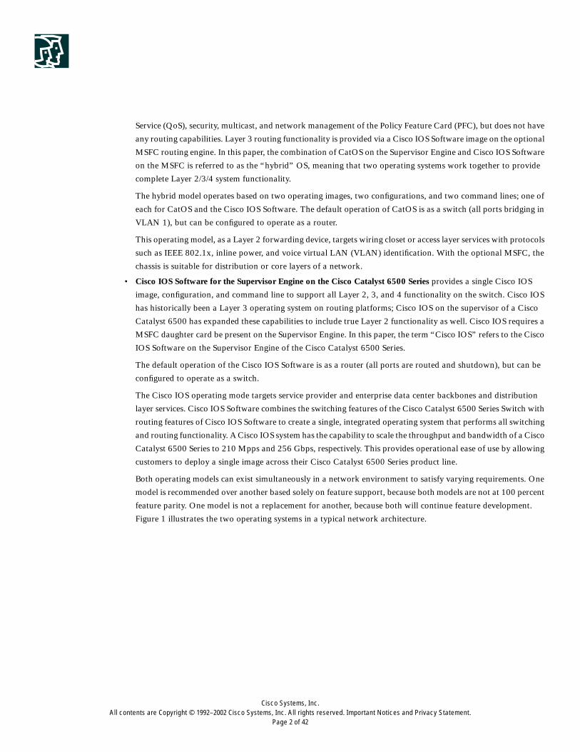
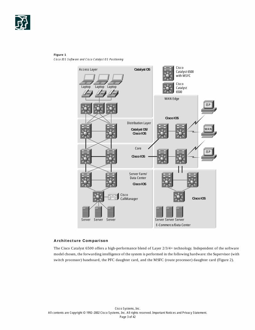
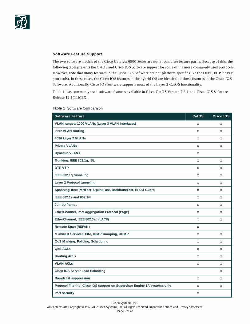
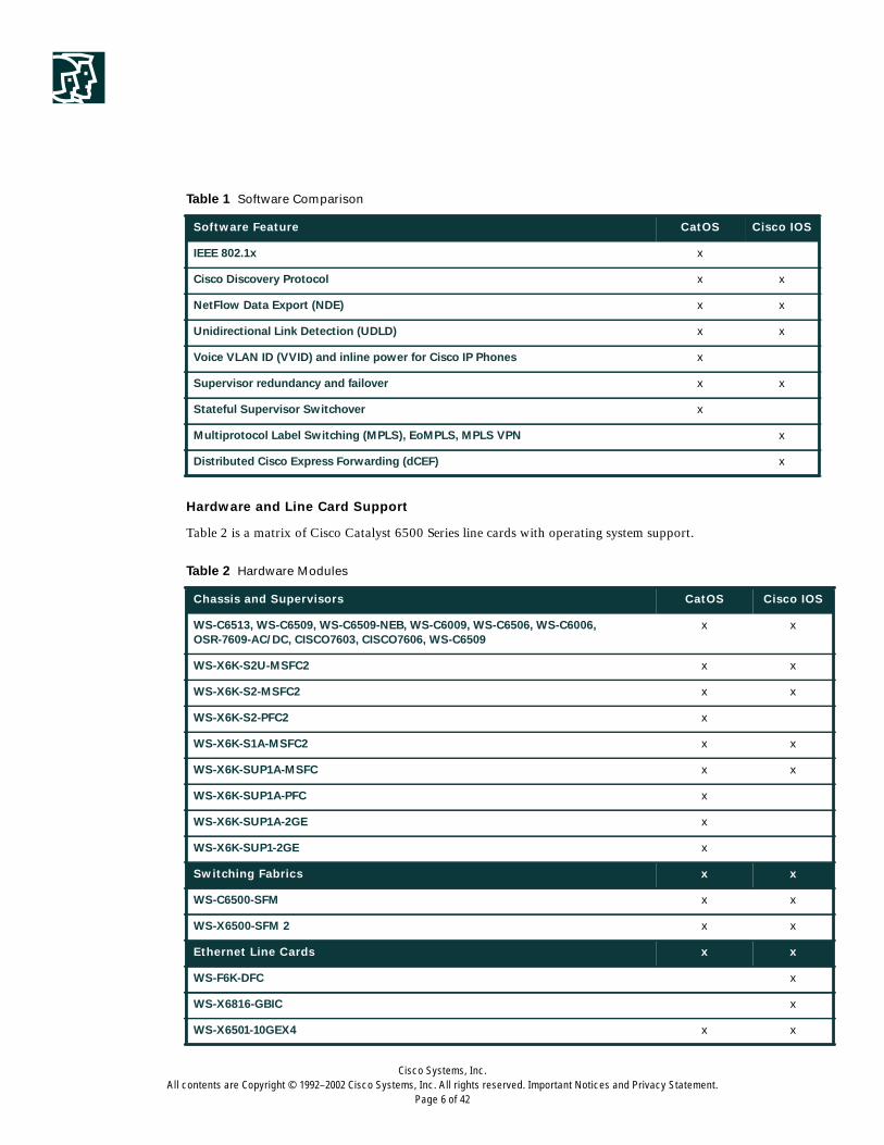
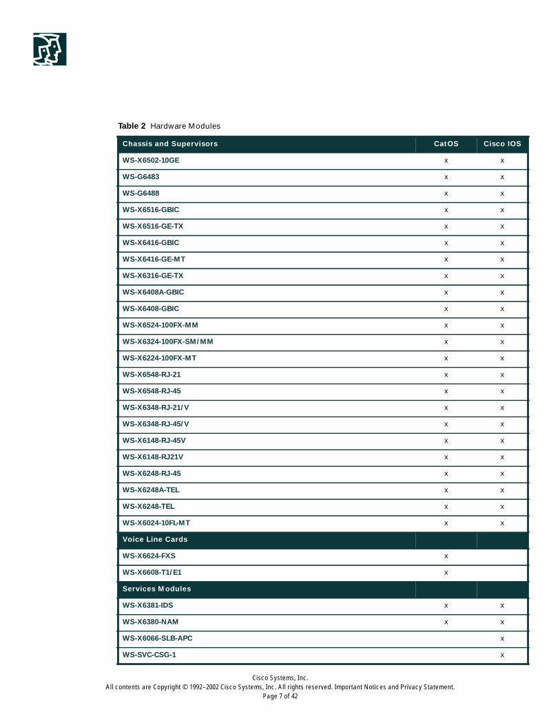
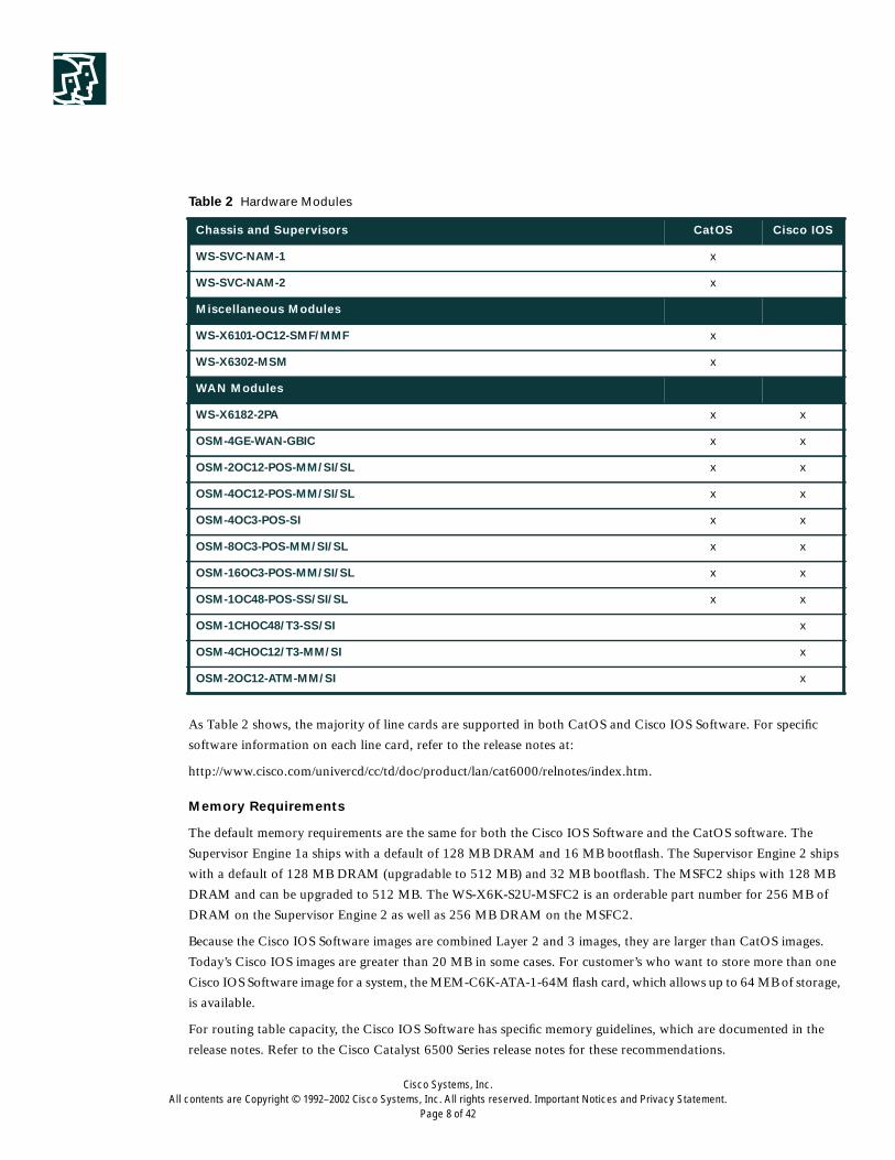
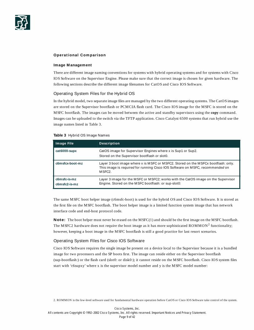
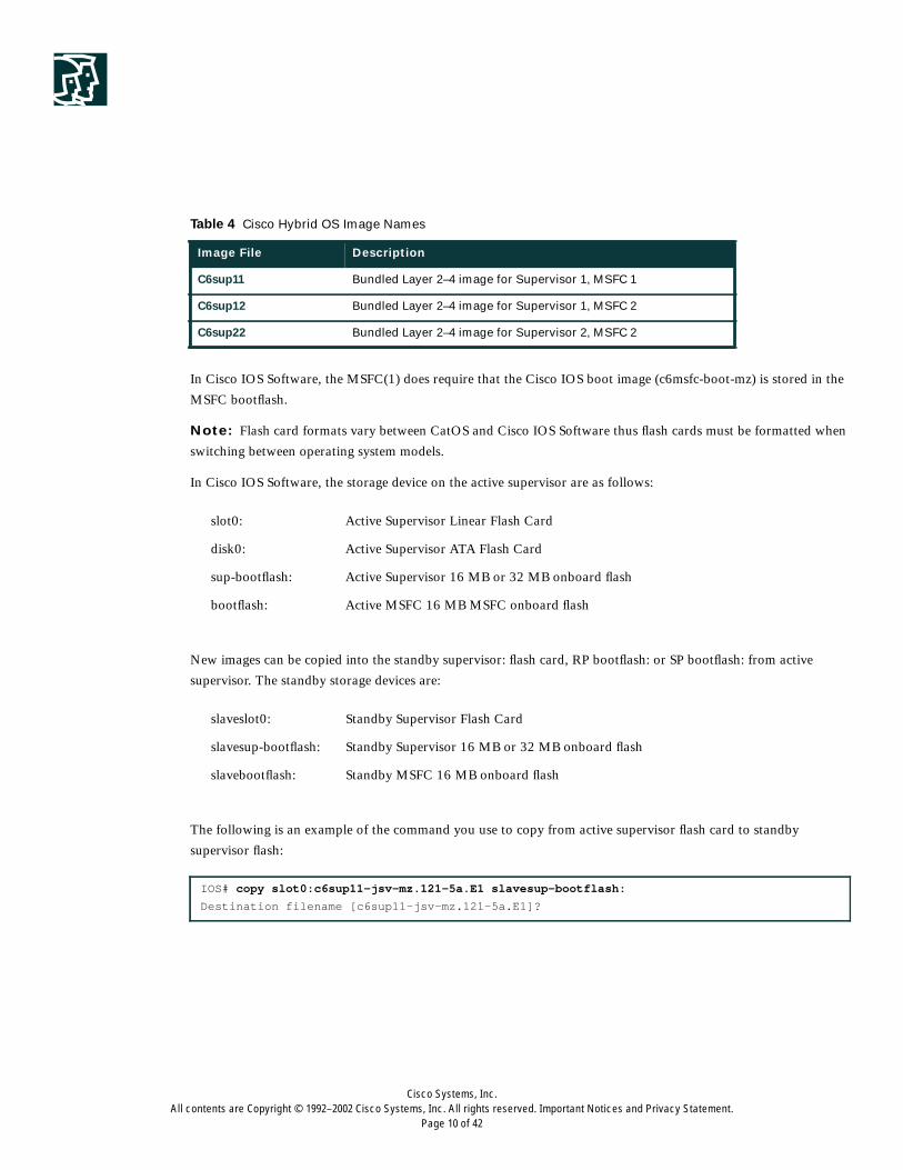
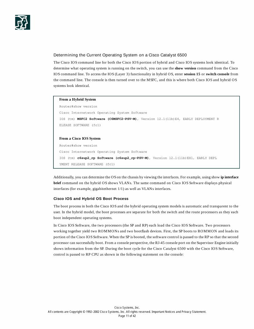
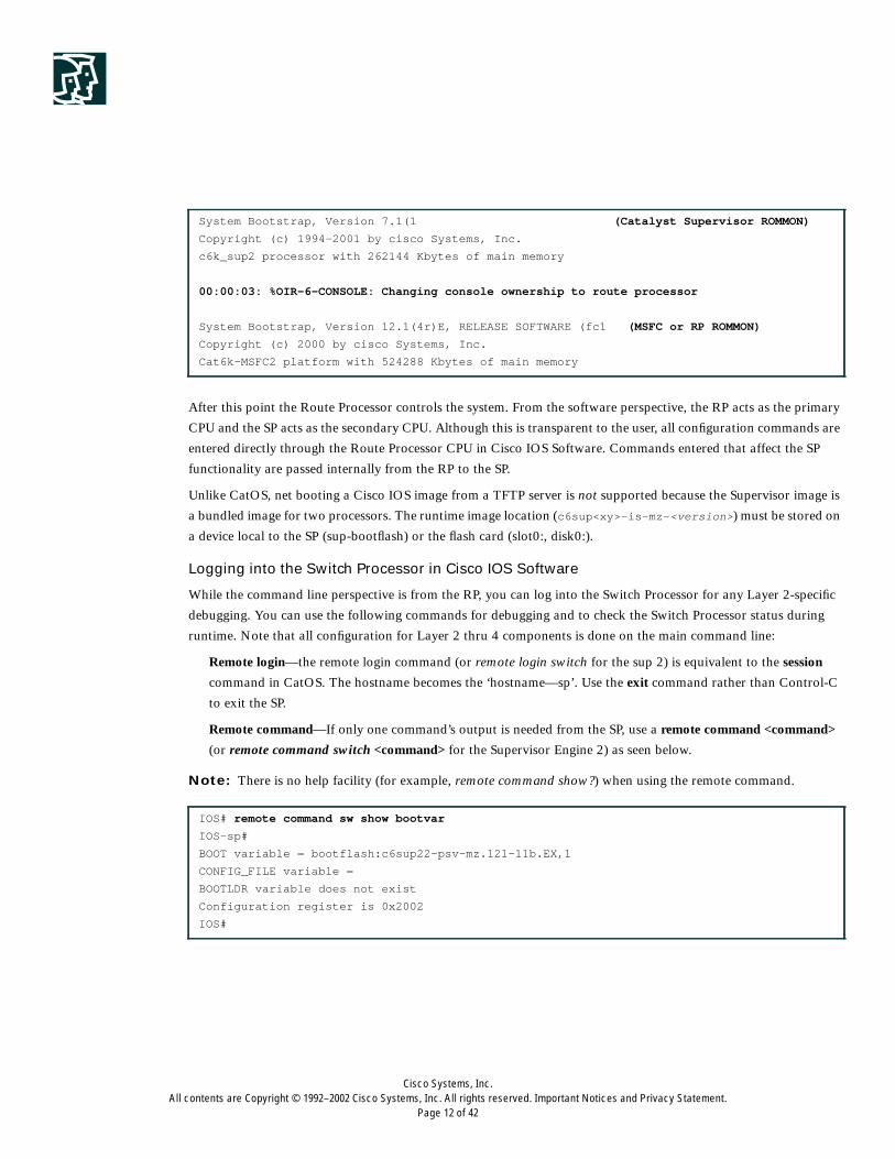
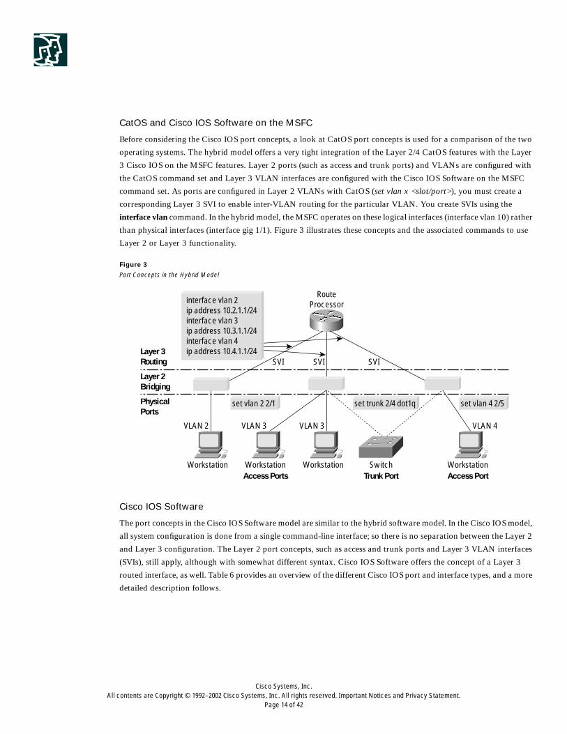
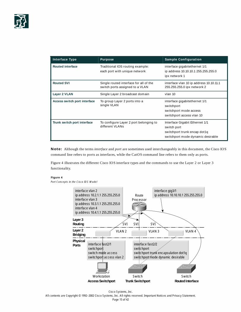
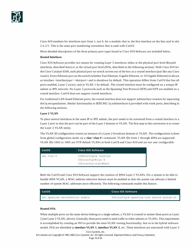
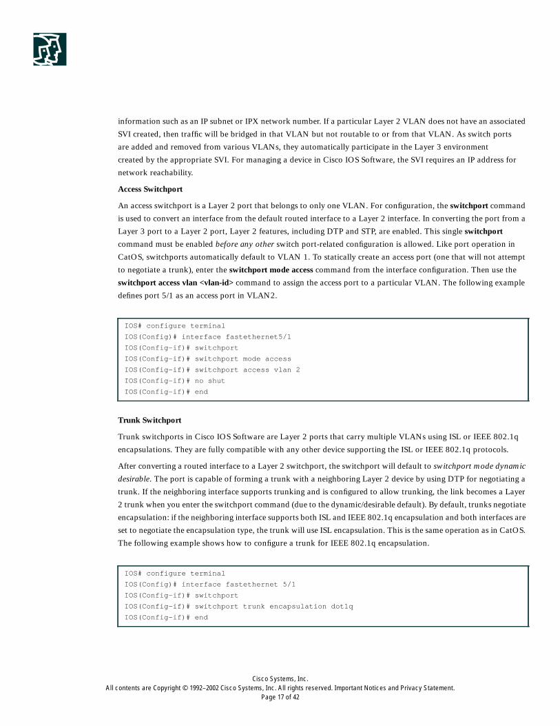
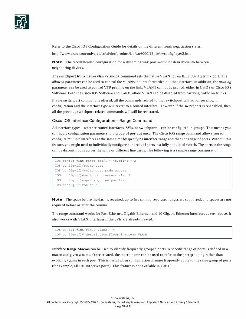
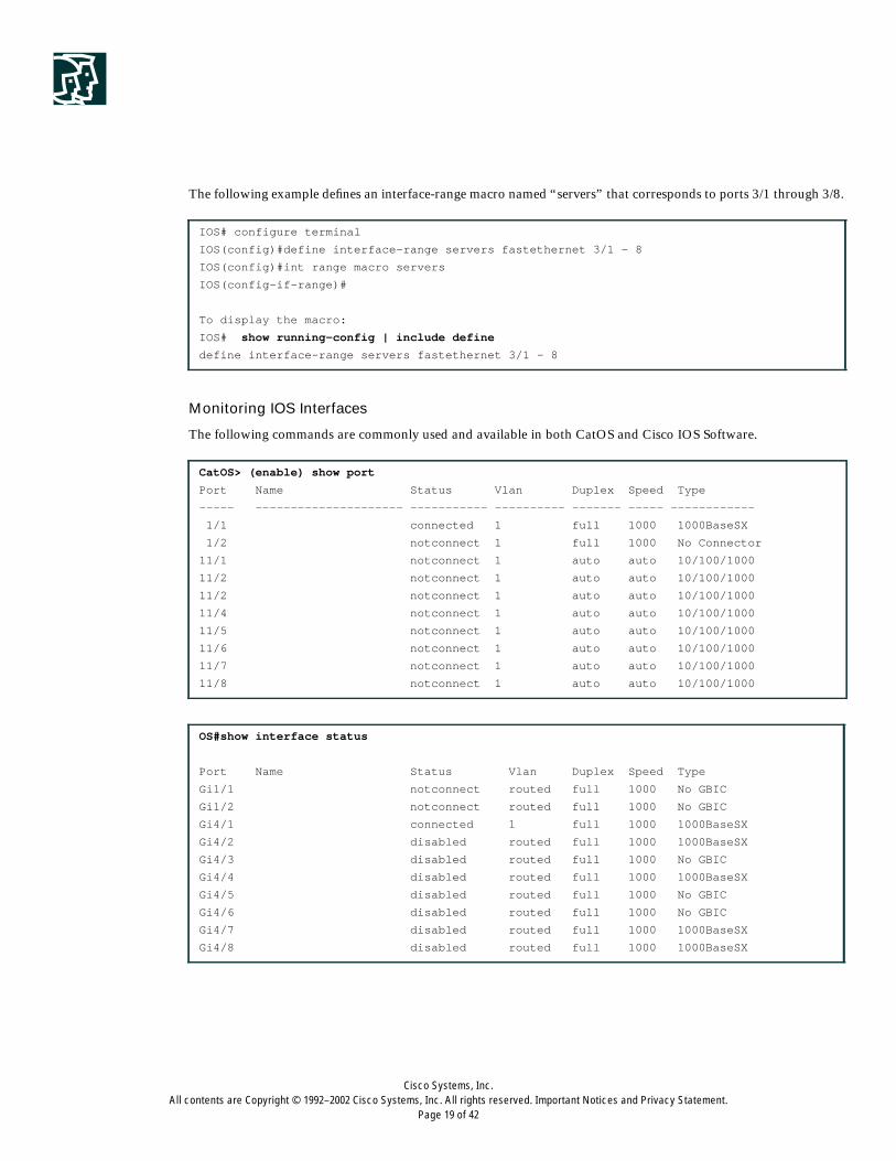
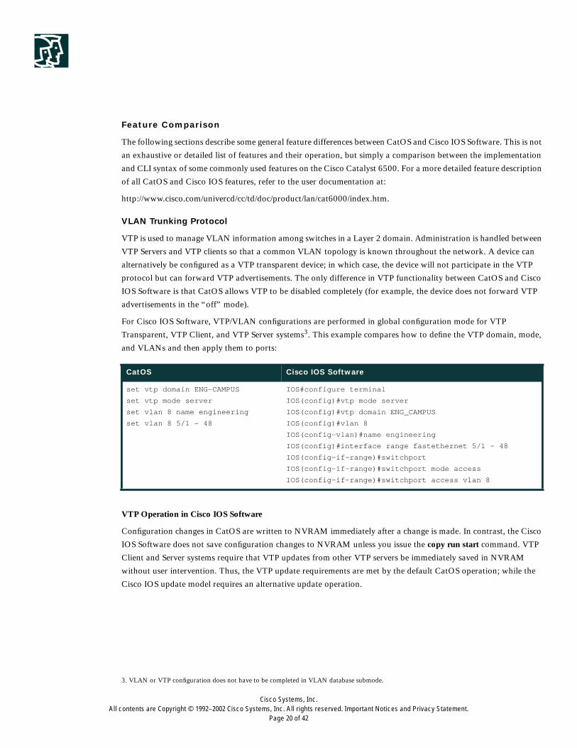
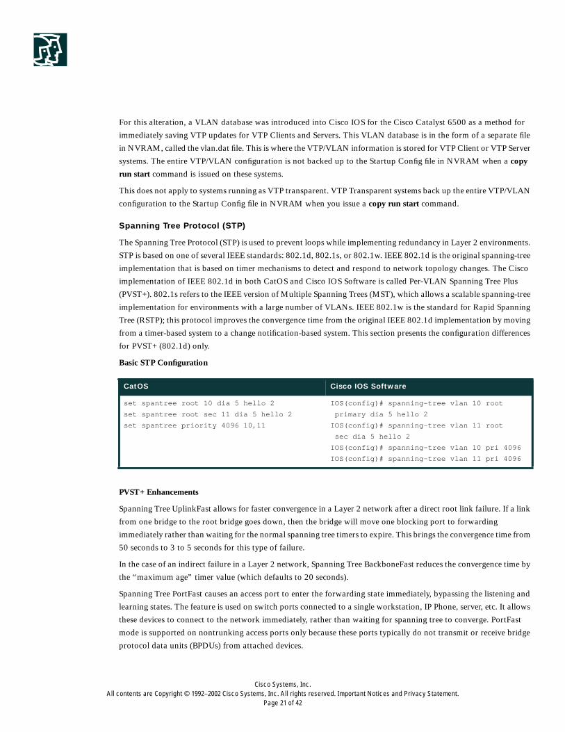
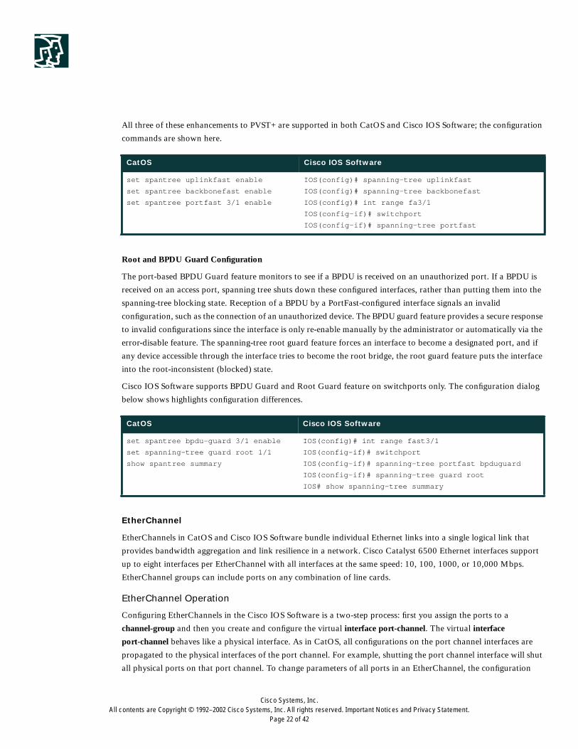
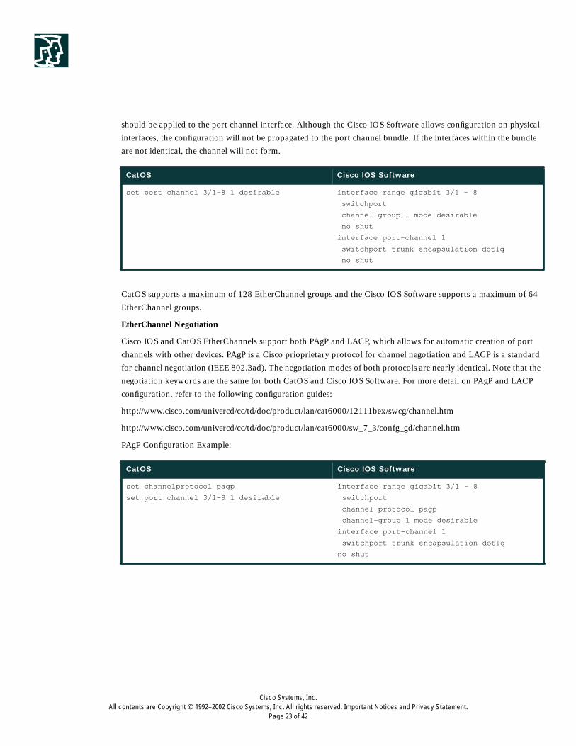
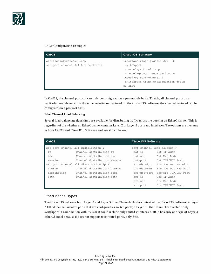
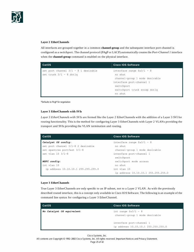
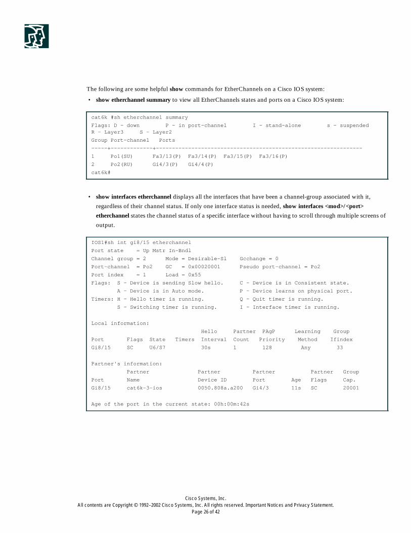
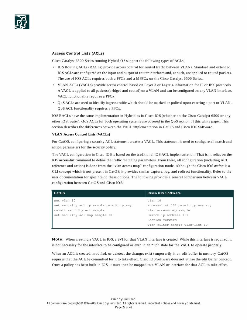
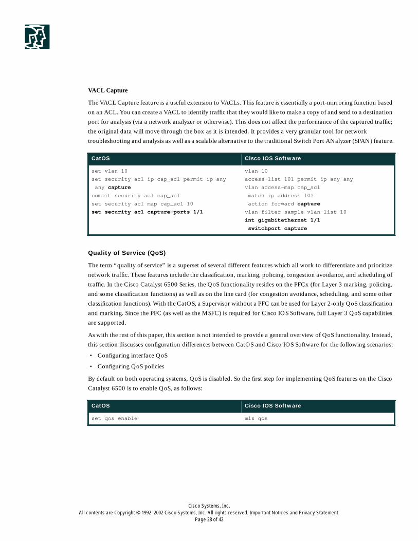
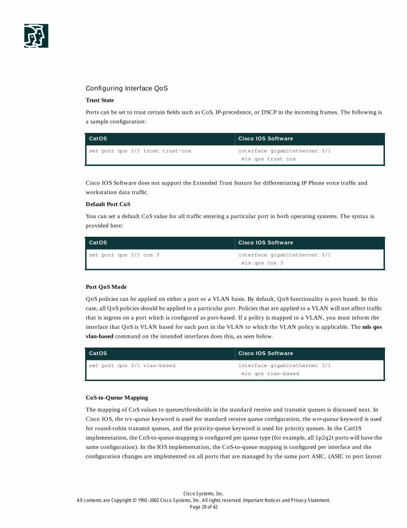
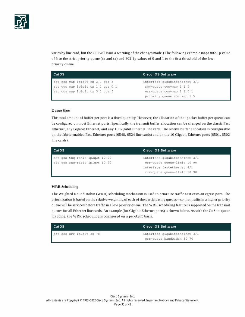
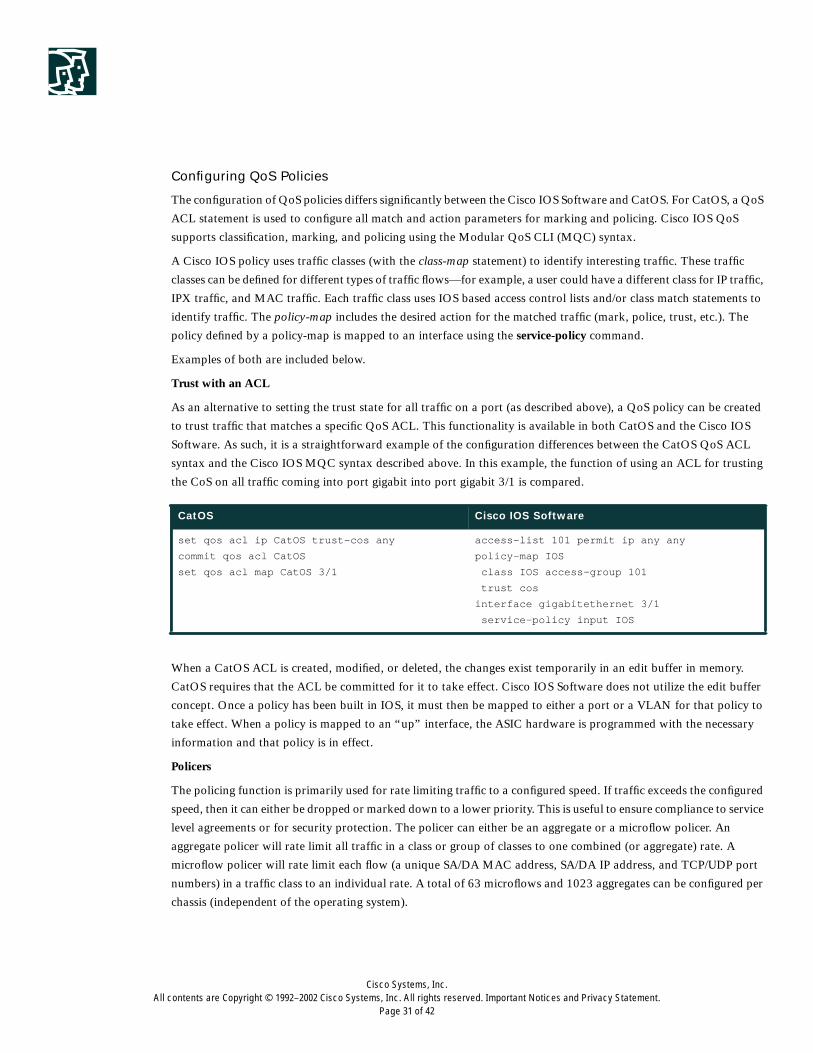
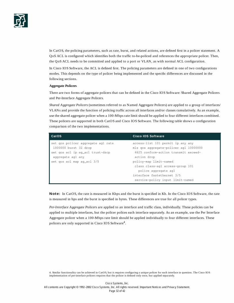
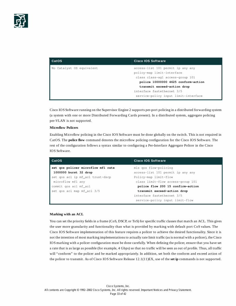
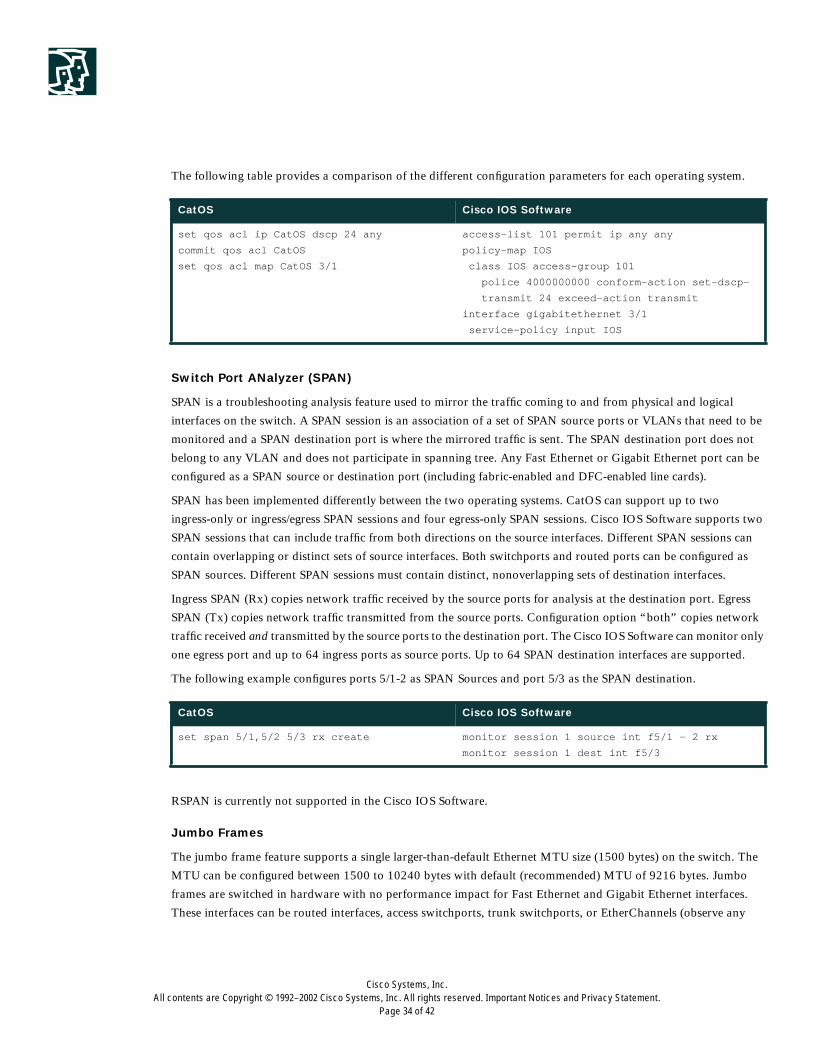
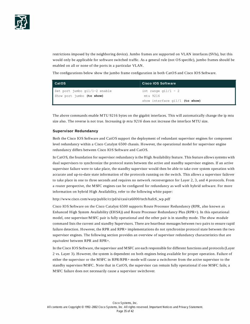
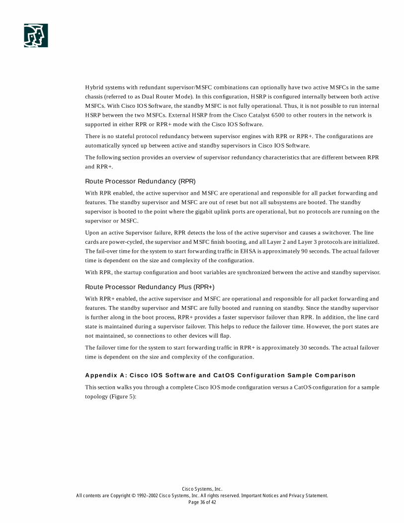
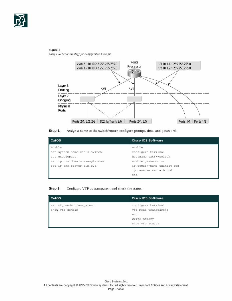
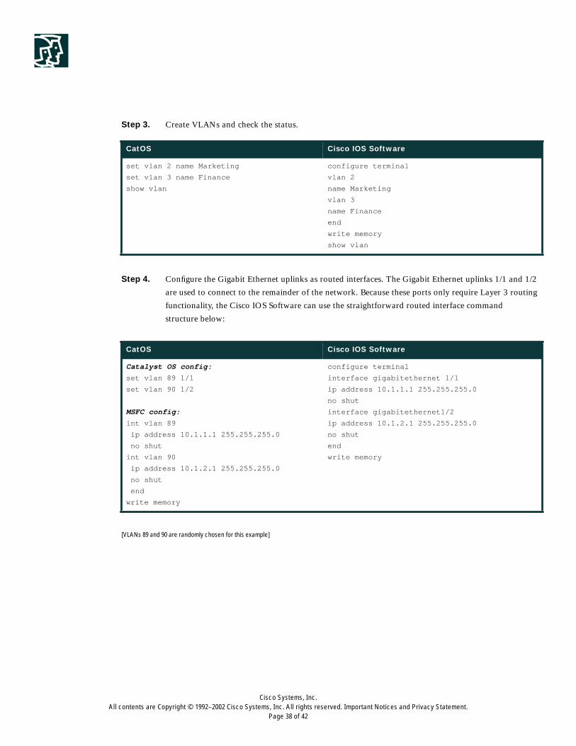
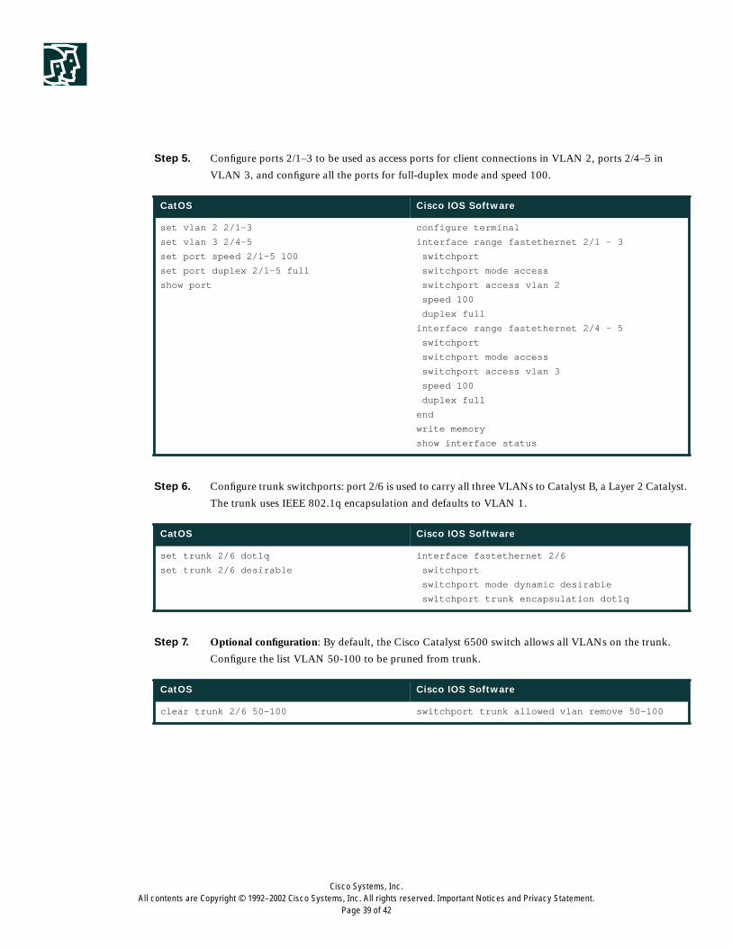
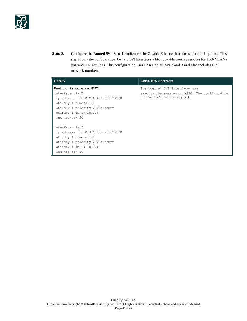
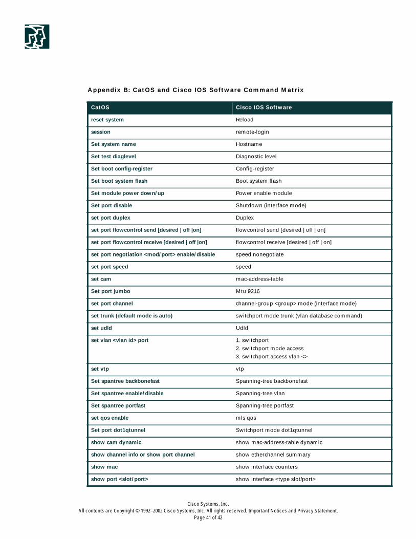
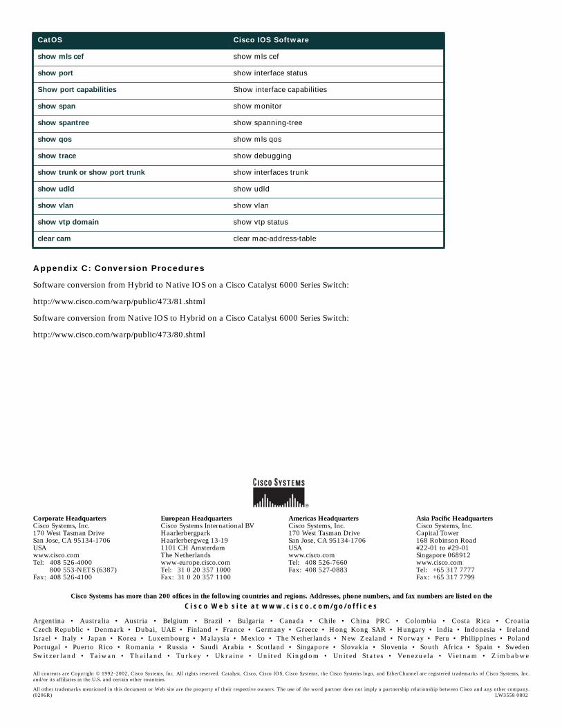


![Catalyst 3750 Switch Cisco IOS Commands - shutdown … · Chapter 2 Catalyst 3750 Switch Cisco IOS Commands shutdown 0-709 Catalyst 3750 Switch Command Reference OL-8552-09 0V] shutdown](https://static.documents.pub/doc/80x56/5b90f2e009d3f22c258cf6a1/catalyst-3750-switch-cisco-ios-commands-shutdown-chapter-2-catalyst-3750-switch.jpg)


