Comparison of three-dimensional optical coherence tomography and high resolution photography for art conservation studies
Desmond C. Adler1, Jens Stenger2, Iwona Gorczynska1, Henry Lie2, Teri Hensick2, Ron Spronk2, Stephan Wolohojian2, Narayan Khandekar2, James Y. Jiang3, Scott Barry3,
Alex E. Cable3, Robert Huber1,4, and James G. Fujimoto1* 1Department of Electrical Engineering and Computer Science, and Research Laboratory of Electronics,
Massachusetts Institute of Technology, Cambridge, Massachusetts 02139 2Harvard University Art Museums, Harvard University, Cambridge, Massachusetts 02138
3Thorlabs Inc, Newton, New Jersey 07860 4Lehrstuhl für BioMolekulare Optik, Fakultät für Physik, Ludwig-Maximilians-Universität München,
Abstract: Gold punchwork and underdrawing in Renaissance panel paintings are analyzed using both three-dimensional swept source / Fourier domain optical coherence tomography (3D-OCT) and high resolution digital photography. 3D-OCT can generate en face images with micrometer-scale resolutions at arbitrary sectioning depths, rejecting out-of-plane light by coherence gating. Therefore 3D-OCT is well suited for analyzing artwork where a surface layer obscures details of interest. 3D-OCT also enables cross-sectional imaging and quantitative measurement of 3D features such as punch depth, which is beneficial for analyzing the tools and techniques used to create works of art. High volumetric imaging speeds are enabled by the use of a Fourier domain mode locked (FDML) laser as the 3D-OCT light source. High resolution infrared (IR) digital photography is shown to be particularly useful for the analysis of underdrawing, where the materials used for the underdrawing and paint layers have significantly different IR absorption properties. In general, 3D-OCT provides a more flexible and comprehensive analysis of artwork than high resolution photography, but also requires more complex instrumentation and data analysis.
1. S. Amadesi, F. Gori, R. Grella, and G. Guattari, "Holographic methods for painting diagnostics," Appl. Opt. 13, 2009-2013 (1974).
2. S. Spagnolo, D. Ambrosini, and G. Guattari, "Electro-optic holography system and digital image processing for in situ analysis of microclimate variation on artworks," Journal of Optics-Nouvelle Revue D Optique 28, 99-106 (1997).
3. D. Paoletti, G. S. Spagnolo, M. Facchini, and P. Zanetta, "Artwork diagnostics with fiberoptic digital speckle pattern interferometry," Appl. Opt. 32, 6236-6241 (1993).
4. P. Targowski, B. Rouba, M. Wojtkowski, and A. Kowalczyk, "The application of optical coherence tomography to non-destructive examination of museum objects," Stud. Conserv. 49, 107-114 (2004).
5. D. Huang, E. A. Swanson, C. P. Lin, J. S. Schuman, W. G. Stinson, W. Chang, M. R. Hee, T. Flotte, K. Gregory, C. A. Puliafito, and J. G. Fujimoto, "Optical coherence tomography," Science 254, 1178-1181 (1991).
6. R. Leitgeb, C. K. Hitzenberger, and A. F. Fercher, "Performance of Fourier domain vs. time domain optical coherence tomography," Opt. Express 11, 889-894 (2003).
#85086 - $15.00 USD Received 9 Jul 2007; revised 9 Nov 2007; accepted 9 Nov 2007; published 16 Nov 2007
(C) 2007 OSA 26 November 2007 / Vol. 15, No. 24 / OPTICS EXPRESS 15972
7. J. F. de Boer, B. Cense, B. H. Park, M. C. Pierce, G. J. Tearney, and B. E. Bouma, "Improved signal-to-noise ratio in spectral-domain compared with time-domain optical coherence tomography," Opt. Lett. 28, 2067-2069 (2003).
8. M. A. Choma, M. V. Sarunic, C. H. Yang, and J. A. Izatt, "Sensitivity advantage of swept source and Fourier domain optical coherence tomography," Opt. Express 11, 2183-2189 (2003).
9. Y. Zhang, B. Cense, J. Rha, R. S. Jonnal, W. Gao, R. J. Zawadzki, J. S. Werner, S. Jones, S. Olivier, and D. T. Miller, "High-speed volumetric imaging of cone photoreceptors with adaptive optics spectral-domain optical coherence tomography," Opt. Express 14, 4380-4394 (2006).
10. R. Huber, D. C. Adler, and J. G. Fujimoto, "Buffered Fourier domain mode locking (FDML): unidirectional swept laser sources for OCT imaging at 370,000 lines per second," Opt. Lett. 31, 2975-2977 (2006).
11. L. Chih-Wei, I. J. Hsu, W. Hsiang-Chen, T. Meng-Tsan, C. C. Yang, and Y. Mei-Li, "Application of optical coherence tomography to monitoring the subsurface morphology of archaic jades," (IEEE, Taipei, Taiwan, 2003), p. 308 Vol.301.
12. M. Gora, M. Pircher, E. Goetzinger, T. Bajraszewski, M. Strlic, J. Kolar, C. K. Hitzenberger, and P. Targowski, "Optical coherence tomography for examination of parchment degradation," Laser Chem. 2006, Article ID 68679, 6 pages (2006).
13. H. Liang, R. Cucu, G. M. Dobre, D. A. Jackson, J. Pedro, C. Pannell, D. Saunders, and A. G. Podoleanu, "Application of OCT to examination of easel paintings," (SPIE-Int. Soc. Opt. Eng, Santander, Spain, 2004), pp. 378-381.
14. T. Arecchi, M. Bellini, C. Corsi, R. Fontana, M. Materazzi, L. Pezzati, and A. Tortora, "Optical coherence tomography for painting diagnostics," in Optical Methods for Art and Archaeology (SPIE-Int. Soc. Opt. Eng, Munich, Germany, 2005), pp. 278-282.
15. T. Arecchi, M. Bellini, C. Corsi, R. Fontana, M. Materazzi, L. Pezzati, and A. Tortora, "A new tool for painting diagnostics: optical coherence tomography," Opt. Spectrosc. 101, 23-26 (2006).
16. H. Liang, M. G. Cid, R. G. Cucu, G. M. Dobre, A. G. Podoleanu, J. Pedro, and D. Saunders, "En-face optical coherence tomography - a novel application of non-invasive imaging to art conservation," Opt. Express 13, 6133-6144 (2005).
17. H. Liang, M. G. Cid, R. Cucu, G. Dobre, B. Kudimov, J. Pedro, D. Saunders, J. Cupitt, and A. Podoleanu, "Optical coherence tomography: a non-invasive technique applied to conservation of paintings," (SPIE-Int. Soc. Opt. Eng, Munich, Germany, 2005), pp. 261-269.
18. I. Gorczynska, M. Wojtkowski, M. Szkulmowski, T. Bajraszewski, B. Rouba, A. Kowalczyk, and P. Targowski, "Varnish thickness determination by spectral domain optical coherence tomography," in Lasers in the Conservation of Artworks, LACONA VI, J. Nimmricheter, W. Kautek, and M. Schreiner, eds. (Berlin-Heidelberg-New York: Springer Verlag, Vienna/Austria, 2005).
19. M. Gora, A. Rycyk, J. Marczak, P. Targowski, and A. Kowalczyk, "From medical to art diagnostics OCT: a novel tool for varnish ablation control," in Coherence Domain Optical Methods and Optical Coherence Tomography in Biomedicine XI(SPIE, San Jose, CA, USA, 2007), pp. 64292V-64297.
20. P. Targowski, M. Gora, and M. Wojtkowski, "Optical coherence tomography for artwork diagnostics," Laser Chem. 2006, Article ID 35373, 11 pages (2006).
21. A. Szkulmowska, M. Gora, M. Targowska, B. Rouba, D. Stifter, E. Breuer, and P. Targowski, "The applicability of optical coherence tomography at 1.55 μm to the examination of oil paintings," in Lasers in the Conservation of Artworks, LACONA VI, J. Nimmricheter, W. Kautek, and M. Schreiner, eds. (Berlin-Heidelberg-New York: Springer Verlag, Vienna/Austria, 2005).
22. P. Targowski, M. Gora, T. Bajraszewski, M. Szkulmowski, B. Rouba, T. Lekawa-Wyslouch, and L. Tyminska-Widmer, "Optical coherence tomography for tracking canvas deformation," Laser Chem. 2006, Article ID 93658, 8 pages (2006).
23. E. S. Skaug, Punch marks from Giotto to Fra Angelico: attribution, chronology, and workshop relationships in tuscan panel painting circa 1330 - 1430. (IIC - Nordic Group, Oslo, 1994).
24. M. S. Frinta, "Observations on the Trecento and early Quattrocento workshop," in The artist's workshop. Studies in the history of art., P. M. Lukehart, ed. (National Gallery of Art, 1993), pp. 18-34.
25. D. Bomford, ed. Art in the making: underdrawings in Renaissance paintings (National Gallery Company, London, 2002).
26. M. Faries, and R. Spronk, eds. Recent development in the technical examination of early Netherlandish painting (Harvard University Art Museums, Cambridge, 2003).
27. G. Mazzoni, ed. Falsi d'autore (Protagon Editori, Siena, 2004). 28. S. W. Huang, A. D. Aguirre, R. A. Huber, D. C. Adler, and J. G. Fujimoto, "Swept source optical coherence
microscopy using a Fourier domain mode locked laser," Opt. Express 10, 6210-6217 (2007). 29. P. M. Andrews, Y. Chen, S. Huang, D. C. Adler, R. Huber, J. Jiang, S. Barry, A. E. Cable, and J. G.
Fujimoto, "High-speed three-dimensional optical coherence tomography imaging of kidney ischemia in vivo," Lab. Invest. In review (2007).
30. R. Huber, M. Wojtkowski, and J. G. Fujimoto, "Fourier domain mode locking (FDML): A new laser operating regime and applications for optical coherence tomography," Opt. Express 14, 3225-3237 (2006).
#85086 - $15.00 USD Received 9 Jul 2007; revised 9 Nov 2007; accepted 9 Nov 2007; published 16 Nov 2007
(C) 2007 OSA 26 November 2007 / Vol. 15, No. 24 / OPTICS EXPRESS 15973
31. D. C. Adler, R. Huber, and J. G. Fujimoto, "Phase-sensitive optical coherence tomography at up to 370,000 lines per second using buffered Fourier domain mode locked lasers," Opt. Lett. 32, 626-628 (2007).
32. R. Huber, D. C. Adler, V. J. Srinivasan, and J. G. Fujimoto, "Fourier domain mode locking at 1050 nm for ultra-high-speed optical coherence tomography of the human retina at 236,000 axial scans per second," Opt. Lett. 32, 2049-2051 (2007).
33. C. K. Hitzenberger, P. Trost, P. W. Lo, and Q. Y. Zhou, "Three-dimensional imaging of the human retina by high-speed optical coherence tomography," Opt. Express 11, 2753-2761 (2003).
34. R. Spronk, and C. Van Daalen, "Two scenes from the Passion at the Harvard Art Museums; a tale of two Antwerp workshops?" in Making and marketing: studies of the painting process in fifteenth- and sixteenth-century Netherlandish workshops, M. Faries, ed. (Brepols Publishers, 2006).
35. D. Koozekanani, K. Boyer, and C. Roberts, "Retinal thickness measurements from optical coherence tomography using a Markov boundary model," IEEE T. Med. Imaging 20, 900-916 (2001).
36. J. A. Izatt, M. R. Hee, G. M. Owen, E. A. Swanson, and J. G. Fujimoto, "Optical coherence microscopy in scattering media," Opt. Lett. 19, 590-592 (1994).
37. E. Beaurepaire, A. C. Boccara, M. Lebec, L. Blanchot, and H. Saint-Jalmes, "Full-field optical coherence microscopy," Opt. Lett. 23, 244-246 (1998).
38. J. W. Hettinger, M. D. P. Mattozzi, W. R. Myers, M. E. Williams, A. Reeves, R. L. Parsons, R. C. Haskell, D. C. Petersen, R. Y. Wang, and J. I. Medford, "Optical coherence microscopy. A technology for rapid, in vivo, non-destructive visualization of plants and plant cells," Plant Physiol. 123, 3-15 (2000).
39. A. D. Aguirre, P. Hsiung, T. H. Ko, I. Hartl, and J. G. Fujimoto, "High-resolution optical coherence microscopy for high-speed, in vivo cellular imaging," Opt. Lett. 28, 2064-2066 (2003).
40. R. A. Leitgeb, M. Villiger, A. H. Bachmann, L. Steinmann, and T. Lasser, "Extended focus depth for Fourier domain optical coherence microscopy," Opt. Lett. 31, 2450-2452 (2006).
41. W. Y. Oh, B. E. Bouma, N. Iftimia, S. H. Yun, R. Yelin, and G. J. Tearney, "Ultrahigh-resolution full-field optical coherence microscopy using InGaAs camera," Opt. Express 14, 726-735 (2006).
42. S. Huang, A. D. Aguirre, R. A. Huber, D. C. Adler, and J. G. Fujimoto, "Swept source optical coherence microscopy using a Fourier domain mode-locked laser," Opt. Express 15, 6210-6217 (2007).
43. J. Dunkerton, and N. Penny, "The infra-red examination of Raphael's "Garvagh Madonna"," in National Gallery Technical Bulletin (NGPL, London, 1993), pp. 6-21.
1. Introduction
Art conservation science inherently requires non-destructive analysis technologies due to the historical value and fragility of many works of art. Optical techniques are attractive for their ability to perform high resolution, non-contact imaging using incident power levels low enough to avoid damaging the sample. Previously, techniques such as holography, speckle pattern interferometry, and optical coherence tomography (OCT) have been applied to the study of artwork [1-4].
OCT is a cross-sectional imaging modality, conceptually similar to ultrasound, that measures sample microstructure by interferometrically detecting the echo time delays of backscattered and backreflected light [5]. OCT is well-suited for art conservation science since it can characterize the layered structures common to many forms of art without physically removing material. OCT instruments utilize low-power near infrared (IR) radiation (typically 700 – 1400 nm) that can penetrate up to several millimeters of material such as varnish, glaze, and paint. The working distance of OCT instruments can be set to several centimeters, enabling non-contact imaging and preventing mechanical damage to the sample. Finally, the axial resolution of OCT instruments can be < 5 μm, which is sufficient for analyzing thin layers of material often present in works of art. With the advent of high-speed OCT using Fourier domain detection techniques [6-8], three-dimensional OCT (3D-OCT) data can now be acquired at up to 75,000 axial lines/sec using spectral / Fourier domain OCT [9] and up to 370,000 axial lines/sec using swept source / Fourier domain OCT with Fourier domain mode locked (FDML) lasers [10].
The first application of OCT in art conservation investigated archaic jade objects that had been naturally whitened by aging [11]. Genuine samples were compared to artificially whitened samples in order to identify cross-sectional features that could aid in the
#85086 - $15.00 USD Received 9 Jul 2007; revised 9 Nov 2007; accepted 9 Nov 2007; published 16 Nov 2007
(C) 2007 OSA 26 November 2007 / Vol. 15, No. 24 / OPTICS EXPRESS 15974
authentication of such objects. Glaze layers on porcelain and faience ceramics have also been investigated using high-speed OCT [4], and the degradation of parchment has been studied using polarization-sensitive OCT [12].
The most active area for OCT in art conservation is the study of paintings. OCT analysis and en face imaging of paintings has been reported using time domain detection [13] as well as spectral / Fourier domain detection [4]. During the process of restoration, for example, it is important to understand the physical characteristics of varnish layers prior to their removal. Measurements of varnish thickness [14-16] and refractive index [17], varnish thickness mapping [18], and controlled laser ablation [19] have all been demonstrated using OCT technology.
OCT also enables optical stratigraphy of paintings through micron-scale imaging of subsurface layers [13, 16, 20]. OCT images have been shown to correlate well with microscopic observations of physically removed samples [14, 15]. OCT visualization of deeply situated layers such as underdrawing depends on the transparency of the overlying material [16]. Qualitative evaluations of paint transparency have been performed using OCT instruments operating at imaging wavelengths of 820 nm, 1300 nm, and 1550 nm [16, 21]. An analysis of canvas deformation was also demonstrated in order to understand the influence of environmental conditions on the painting degradation [16, 22].
An important and still unresolved problem in the technical examination of art work is the structural characterization of small tool marks. One important example is the gilded surfaces of panel paintings from the early Italian Renaissance, where halos and garments were often adorned with impressions of punches in various shapes. The historical development of the punch technique, its spread from Italy to Bohemia and France, the manufacture of tools, the relevance of punch marks for problems of attribution, and questions regarding artists and their workshops sharing or handing down tools have all been important research areas. Perhaps most importantly, gold punch decorations can be used to link a particular painting to potential creators, since the motif punches or formalized clusters of punches are uniquely characteristic of specific workshops [23, 24].
3D structural characterization of punch marks is particularly difficult to obtain when paint, discolored varnish, or other material is deposited on top of the tool mark. Most studies in this field have been based on visual examination, hand sketches, or conventional photography and therefore often fail to observe fine details of the punch marks. Marks made with the same tool can be misidentified as being made with different tools, or vice versa. Therefore, a 3D microscopic imaging technique such as 3D-OCT is potentially valuable for analyzing punches, where microscopic defects in the marks could serve as “fingerprint” characteristics of a specific punch tool.
Another key aspect in the technical and historical understanding of Renaissance paintings is the study of the underdrawing [25, 26]. These preparatory drawings can be revealed by IR photography, which exploits the fact that paint becomes more transparent in the IR spectral range while the carbon-based underlying drawings absorb even at long wavelengths. This technique often gives important information about the genesis of a painting, because it can show revisions and the evolution of the artist's ideas at an early but crucial stage of the creative process. However, some pigments used in more superficial layers also have absorption bands in the near IR, and IR photography cannot separate these layers from the layer containing the underdrawing. IR photography does not provide information regarding which layer the underdrawing is located in. 3D-OCT, on the other hand, can provide a 3D map of layer stratification, and absorption in the paint layer can be separated from the underdrawing. Recently, OCT was used for the first time to image the underdrawing of a painting [16]. However OCT has not previously been compared to high resolution digital IR photography.
In this study, we demonstrate 3D-OCT imaging for the analysis of gold punchwork and underdrawing in three historical paintings. For each painting, high resolution digital color
#85086 - $15.00 USD Received 9 Jul 2007; revised 9 Nov 2007; accepted 9 Nov 2007; published 16 Nov 2007
(C) 2007 OSA 26 November 2007 / Vol. 15, No. 24 / OPTICS EXPRESS 15975
photography or high resolution digital IR photography is also applied and the results are compared to the 3D-OCT data. Gold punchwork is investigated in two paintings: “Marriage of the Virgin”, produced by the Master of the Orcagnesque Misericordia (active between 1375 – 1400); and “San Marco”, produced by Daniel V. Thompson Jr around 1920 using the punch tools of Frederico Ioni, a well known restorer and notorious forger of Italian Renaissance art [27]. In both cases, 3D-OCT is able to detect micron-scale features in the punchwork that cannot be detected using high resolution photography. This is especially evident in “Marriage of the Virgin”, where an aged varnish layer obscures the gold layer. These features can conceivably be used to identify other paintings made using the same punch tools.
Underdrawing is investigated in one painting: “Arrest of Christ”, produced by an anonymous artist around 1520. In this piece, the significantly different IR absorption properties of the underdrawing and overlying material give good results using high resolution IR photography. The underdrawing can be clearly visualized beneath the paint and varnish layers using either high resolution IR photography or 3D-OCT, although the 3D-OCT instrument is also capable of analyzing all of the layers in the painting. In general, 3D-OCT can provide a more comprehensive and detailed characterization of historical artwork than high resolution photography, but requires more complex instrumentation.
2. Experimental Setup
2.1. Three-Dimensional Optical Coherence Tomography System
The 3D-OCT instrument has been described previously [28, 29], but is briefly explained here for reference purposes. The instrument uses a swept source / Fourier domain OCT configuration to enable high-speed volumetric imaging. A buffered FDML laser is used as the light source [10, 30-32], providing unidirectional wavelength sweeps at 42,000 sweeps/sec. The laser tunes over a range of 118 nm at a center wavelength of 1287 nm, providing an axial image resolution of 9.3 μm in air or ~6 μm in material such as paint or varnish. The average output power is 14 mW. Although FDML lasers with sweep rates up to 370,000 sweeps/sec have been demonstrated [10], the data acquisition system used for this study is not compatible with operation at such speeds.
The Michelson interferometer, data acquisition system, and imaging microscope are based on a modified commercial OCT system (Thorlabs Inc.). A portion of the laser output is routed to a Mach-Zehnder interferometer, which generates a clock signal for resampling the OCT data onto a uniform optical frequency grid prior to Fourier transformation. The remainder of the laser output is routed to the Michelson interferometer and imaging microscope. The microscope provides a 30 μm spot at a working distance of ~3 cm and uses a pair of scanning galvanometers to translate the beam in the X and Y (transverse) dimensions. The imaging optics were mounted to a horizontal rail with X, Y and Z (axial) translation to facilitate imaging of the samples while they were mounted vertically on an easel. In order to reduce the effects of specular backreflections in the OCT images, the paintings were tilted at ~30° relative to the OCT beam.
The data acquisition system uses a 100 megasample/sec, 14 bit analog-to-digital converter to sample the interference signal from the Michelson interferometer, and performs a fast Fourier transform to generate each axial image line. With ~10 mW of power incident on the sample, a sensitivity of 100 dB and an imaging range of 3 mm in air are achieved. After the volumetric data sets were acquired, commercial 3D rendering software (ResolveRT, Mercury Computer Systems Inc.) was used to produce en face, cross-sectional, and summed voxel projection OCT images.
#85086 - $15.00 USD Received 9 Jul 2007; revised 9 Nov 2007; accepted 9 Nov 2007; published 16 Nov 2007
(C) 2007 OSA 26 November 2007 / Vol. 15, No. 24 / OPTICS EXPRESS 15976
2.2. High Resolution Photography System
A state-of-the-art digital camera was used to provide high resolution en face images of the artwork with relatively simple instrumentation and data analysis requirements. The CCD array used in the camera back consists of 7216 x 5412 pixels with a 6.8 x 6.8 μm pixel size (P45+, Phase One Inc.). The CCD has a 16 bit color depth and is responsive from ~400 – 1100 nm. The lens (Apo-Sironar digital HR, Rodenstock Inc.) has a 60 mm focal length and is matched to the CCD array to provide a theoretical resolution of 10 μm for visible wavelengths under optimized conditions. The camera aperture was set to an f-number of 8 to achieve the best trade-off between depth of field and transverse resolution. At a working distance of 6 cm, the field of view is 52 x 39 mm. The actual transverse resolution was estimated by measuring the width of edge features in color images. This measurement indicated that an actual transverse resolution of ~20 μm is attained, which is degraded compared to the theoretical value since the CCD is slightly overfilled and the lens was not used at its optimal working distance of 1 m.
For high resolution color photography of the gold punchwork samples, a bandpass filter that transmitted from 350 – 700 nm was placed in front of the camera lens. Two halogen-tungsten lamps were used for illumination, operating at 120 V and 750 W with a color temperature of 3200 K. One lamp was placed on each side of the camera at a distance of 1.5 m from the paintings. The angle between the paintings and the lamps was 45°. The exposure time was set to 33 ms to fully utilize the dynamic range of the CCD. For high resolution IR photography of underdrawing, a longpass filter was placed in front of the camera lens. The filter transmitted from 900 nm to > 1100 nm, which is the cutoff wavelength of the CCD. The same illumination setup was used for IR photography as for color photography, but the exposure time was increased to 1 s to fully utilize the dynamic range of the CCD. After each photograph was acquired, photo editing software (Capture One PRO, Phase One) was used to produce en face images corresponding to the 3D-OCT data of the same painting features.
3. Results
3.1 Gold Punchwork – “Marriage of the Virgin”
“Marriage of the Virgin” is a painting on a wooden support, created by the Master of the Orcagnesque Misericordia (active between 1375 and 1400 AD). This piece contains a large amount of gold punchwork detailing as well as an aged varnish surface layer that makes visual inspection of the punch details difficult. Figure 1(A) shows a standard-resolution photograph of the painting, which is 37.4 x 23.0 cm (X x Y) in dimension. The red boxes indicate two regions of the painting that contain gold punchwork detailing. Figure 1(B-C) shows enlarged views of the regions of interest. The yellow arrows indicate three specific circular punches that were analyzed using 3D-OCT and high resolution color photography.
3D-OCT data sets of the gold punches were acquired, each consisting of 512 x 512 x 512 pixels (X x Y x Z) and spanning a region of 4 x 4 x 3 mm. Each dataset was acquired in ~6 s. Figure 2(A) shows a synthetic en face OCT image of the first circular punch, generated using a summed voxel projection technique. In this technique, an en face image is formed by axially summing each line in the volumetric data set over the entire depth range of the volume, similarly to methods in ophthalmic 3D-OCT imaging for en face visualization of the retina [33]. The outlines of the large circular punch and surrounding small punches are clearly visible in the OCT image. Since a 3D dataset is acquired, cross-sectional images can also be generated with exact registration to the en face view. The red and blue dashed lines indicate the locations of the cross-sectional images shown in Fig. 2(B) and Fig. 2(C). The cross-sectional images reveal a 50 – 220 μm thick varnish layer, indicated by the white arrows, uniformly deposited on top of the gold layer. The punch depth is shown to be 100 – 120 μm.
#85086 - $15.00 USD Received 9 Jul 2007; revised 9 Nov 2007; accepted 9 Nov 2007; published 16 Nov 2007
(C) 2007 OSA 26 November 2007 / Vol. 15, No. 24 / OPTICS EXPRESS 15977
Fig. 1. “Marriage of the Virgin”, 1375 – 1400. A. Photograph of the painting with regions of interest indicated by red boxes. Painting dimensions are 37.4 x 23.0 cm. B. Enlarged view of the first region of interest, showing the location of the first gold punch. C. Enlarged view of the second region of interest, showing the locations of the second and third gold punches.
Fig. 2. OCT images of the first gold punch in “Marriage of the Virgin.” A. En face image formed by summed voxel projection, where every line in the 3D dataset is axially summed over the entire depth range. Red and blue lines indicate the locations of the cross sectional images. B. XZ cross sectional image. C. YZ cross sectional image. A surface layer of varnish (arrows) is present on top of the gold layer, which obscures the fine details of the punch.
3D-OCT imaging also enables the selective visualization of microstructural features at
arbitrary sample depths and orientations, which can be used to visualize the gold layer separately from the varnish layer. This concept is illustrated in Fig. 3(A). The dashed line indicates the orientation of a plane parallel to the surface of the painting. This plane can be translated perpendicularly to the surface, as indicated by the red arrows, and a single OCT image can be extracted at each location. Fig, 3(B) shows the resulting “single-slice” en face OCT image extracted when the plane is positioned inside the varnish layer. Note the lack of detail and diffuse scattering produced by the varnish. Fig, 3(C) shows the single-slice en face OCT image extracted when the plane is positioned deeper in the sample, such that the plane intersects the gold layer. Compared to the en face image formed by summed voxel projection
#85086 - $15.00 USD Received 9 Jul 2007; revised 9 Nov 2007; accepted 9 Nov 2007; published 16 Nov 2007
(C) 2007 OSA 26 November 2007 / Vol. 15, No. 24 / OPTICS EXPRESS 15978
in Fig. 2(A), the image in Fig. 3(C) shows significantly more detail since the confounding effects of the varnish layer have been removed. Since gold is highly reflective at NIR wavelengths, the OCT beam cannot penetrate through the gold layer. Therefore the OCT system generates a microstructural 3D relief map of the gold lying beneath the varnish layer. A complete flythrough of this punch is available as a linked multimedia file, showing the extracted single-slice en face OCT images as a function of sample depth. Note that the painting is actually tilted in both X and Y as shown in Fig. 2(B) and Fig. 2(C), and the single-slice en face image plane is also tilted in these two dimensions.
Fig. 3. A. YZ cross-sectional image of the first gold punch. Dashed line shows the orientation of an image plane parallel to the surface of the painting. The plane can be translated perpendicularly to the surface. B. Single-slice en face image obtained by positioning the plane in the varnish layer. C. Single-slice en face image obtained by positioning the plane deeper in the sample, such that the plane intersects the gold layer. More detail is apparent when the gold layer is analyzed separately from the varnish layer. Multimedia file is 3.2 megabytes.
To evaluate the potential for 3D-OCT to identify punches created with the same tool, two
additional regions were imaged and compared with high resolution color photographs. Single-slice en face OCT images of the gold layer were extracted for each punch using the method described above. Figure 4(A-C) shows the single-slice en face OCT images corresponding to the 1st, 2nd, and 3rd punches, respectively. Several characteristic features are visible in each punch, including a small ridge at 10 o’clock and a widened depression at 1 o’clock, as indicated by the red arrows. These features are nearly identical in each punch and most likely represent imperfections in the tool used to create the punches. This demonstrates that 3D-OCT is able to visualize features that can be used to identify punch tools and, therefore, potentially identify other works of art produced using the same tool.
Figure 4(D-F) shows high resolution color photographs of the same three punches as shown in Fig. 4(A-C). The varnish layer heavily obscures the fine details of each punch, making it impossible to detect the characteristic features visible in the OCT images. Surface scratches in the gold and discoloration in the materials further add to the difficulty in analyzing the punches. In this example, 3D-OCT is much better suited for characterizing the punches than high resolution photography.
#85086 - $15.00 USD Received 9 Jul 2007; revised 9 Nov 2007; accepted 9 Nov 2007; published 16 Nov 2007
(C) 2007 OSA 26 November 2007 / Vol. 15, No. 24 / OPTICS EXPRESS 15979
Fig. 4. A-C. En face OCT images of the first, second, and third gold punches in “Marriage of the Virgin”, obtained by synthesizing images from a plane intersecting the gold layer. Red arrows indicate unique identifying features, suggesting that the same tool was used to create all three punches. D-F. High resolution color photographs of the same three punches. Identifying features are not visible with photography due to the lack of depth selectivity and the presence of the surface varnish layer.
3.2 Gold Punchwork – “San Marco”
“San Marco” is a panel painting created in 1923 by Daniel V. Thompson Jr. in Sienna, Italy under the supervision of Frederico Ioni. At that time, Thompson was a student of Edward Waldo Forbes, an early director of the Harvard University Art Museums in Cambridge, Massachusetts. Ioni was a well known expert in early Italian painting technique and worked as a restorer. Thompson visited him in 1923 to learn about Italian tempera painting technique and for that purpose copied the “San Marco” panel. Today we know that Ioni was not only a restorer, but also created a large number of forgeries.
The copy of “San Marco” contains a large amount of gold punchwork detailing, but does not possess a surface layer of varnish. Two types of gold punches were analyzed in this sample. The first is a large circular punch that is somewhat similar to those imaged in “Marriage of the Virgin.” The second is a “waffle iron” punch that is not commonly found elsewhere. Figure 5(A) shows a photograph of the painting, which is 20.8 x 35.8 cm (X x Y). The red boxes indicate two regions of the painting that contain gold punchwork. Figure 5(B-C) show enlarged views of the regions of interest. The yellow arrows indicate three specific punches that were analyzed using 3D-OCT and high resolution color photography. The first is a large circular punch, while the second and third are waffle iron punches. Since Thompson was using the punch tools of Ioni, a method for uniquely identifying these punch tools would be valuable for detecting forged works that Ioni may have created.
#85086 - $15.00 USD Received 9 Jul 2007; revised 9 Nov 2007; accepted 9 Nov 2007; published 16 Nov 2007
(C) 2007 OSA 26 November 2007 / Vol. 15, No. 24 / OPTICS EXPRESS 15980
Fig. 5. “San Marco,” circa 1920 A. Photograph of the painting with regions of interest indicated by red boxes. Painting dimensions are 20.8 x 35.8 cm. B. Enlarged view of the first region of interest, showing the location of the first (circular) gold punch. C. Enlarged view of the second region of interest, showing the locations of the second and third (waffle iron) gold punches.
3D-OCT datasets were acquired for the three punches, with each dataset consisting of 800
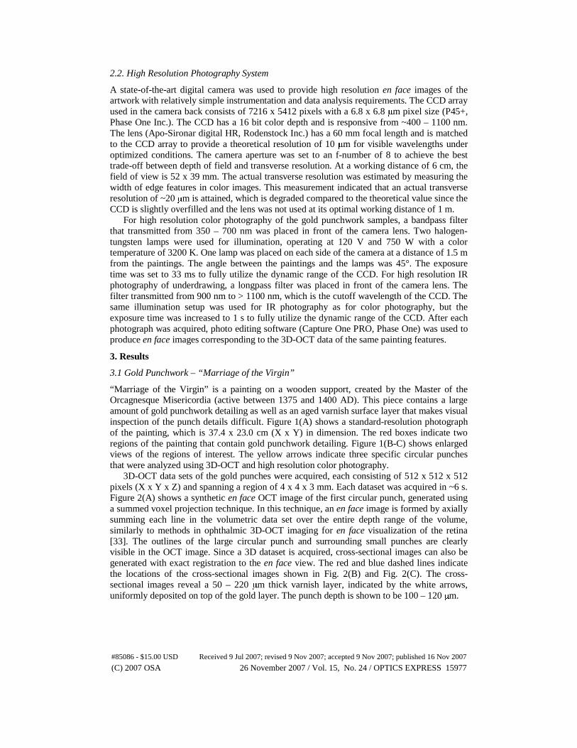
x 800 x 512 pixels and spanning 6 x 6 x 3 mm. Single-slice en face OCT images were again created by extracting images from a plane parallel to the surface of the painting. The plane was positioned such that it intersected the gold layer. Figure 6(A) shows a single-slice en face OCT image of the first large circular punch. Comparing this image to Fig. 4(A-C), 3D-OCT can clearly distinguish between the two types of circular punches in “Marriage of the Virgin” and “San Marco.” The red and blue dashed lines in Fig. 6(A) indicate the locations of the cross-sectional images shown in Fig. 6(B-C). There is no surface layer present and the circular punch depth is shown to be 100 – 200 μm, which is significantly deeper than the “Marriage of the Virgin” punches. Figure 7(A) and Fig. 7(D) show a single-slice en face OCT image and high resolution color photograph of the same large circular punch, respectively. In the absence of a varnish layer, the color photograph can provide a relatively detailed image but cannot be used to measure punch depths or other 3D features.
3D-OCT is also capable of detecting unique identifying features in the waffle iron punches. Figure 7(B-C) shows single-slice en face OCT images of the two waffle iron punches identified in Fig. 5(C). The images were generated by setting the image plane to near the bottom of the gold layer. Note that the waffle pattern is disrupted in a similar manner at this depth for both punches, as shown by the red arrows. This indicates that the tool used to create these punches does not have a uniform surface profile, which may be useful for identifying other works created by the same tool and artist. Figure 7(E-F) shows high resolution color photographs of the same waffle iron punches. The photographs are not able to discern the same depth-dependant changes in the punch profiles as the 3D-OCT instrument and are therefore not as useful for uniquely identifying the punch tool.
#85086 - $15.00 USD Received 9 Jul 2007; revised 9 Nov 2007; accepted 9 Nov 2007; published 16 Nov 2007
(C) 2007 OSA 26 November 2007 / Vol. 15, No. 24 / OPTICS EXPRESS 15981
Fig. 6. OCT images of the first gold punch in “San Marco.” A. Single-slice en face image formed by placing the image plane parallel to the painting surface and at a depth that intersects the gold layer. Red and blue lines indicate the locations of the cross sectional images. B. XZ cross sectional image. C. YZ cross sectional image. No varnish layer is present, and the punch depth is larger than in “Marriage of the Virgin”.
Fig. 7. A-C. Single-slice en face OCT images of the first, second, and third gold punches in “San Marco”, obtained by synthesizing images from a plane intersecting the gold layer. Red arrows indicate unique identifying features, suggesting that the same tool was used to create both waffle iron punches. D-F. High resolution color photographs of the same three punches. Identifying features are not visible with photography due to the lack of depth selectivity.
#85086 - $15.00 USD Received 9 Jul 2007; revised 9 Nov 2007; accepted 9 Nov 2007; published 16 Nov 2007
(C) 2007 OSA 26 November 2007 / Vol. 15, No. 24 / OPTICS EXPRESS 15982
3.3 Underdrawing – “Arrest of Christ”
“Arrest of Christ” is an early Netherlandish panel painting created around 1520 AD by an anonymous artist. This piece contains several layers of material, including an underdrawing executed in a dry medium, paint, and varnish. Here, 3D-OCT is compared with high resolution IR photography to determine which technique is best suited for imaging the underdrawing. Figure 8(A) shows a photograph of the painting, which is 33.8 x 13.5 cm (X x Y) in dimension. Figure 8(B) shows an IR photograph that reveals the macroscopic features of the underdrawing layer. In addition to a sketch of the scene, there is a message written in the upper left portion of the painting. It has been speculated that the inscription might refer to the narrative of the scene [34]. The red boxes indicate two regions of the painting that contain underdrawing features. Figure 8(C-D) shows enlarged views of the regions of interest. The red arrows indicate three specific underdrawing features that were analyzed using 3D-OCT and high resolution IR photography. The first feature is a portion of the last letter from the inscription, while the second and third features are lines from one of the robes.
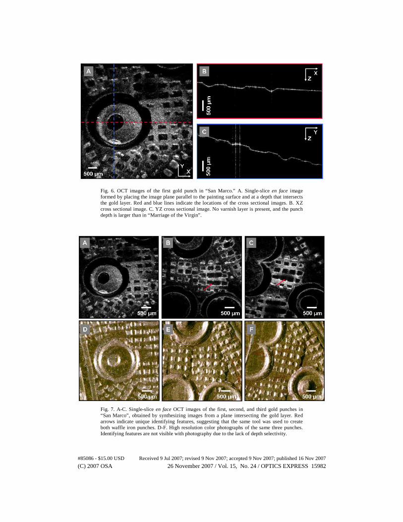
3D-OCT datasets were acquired for the three underdrawing features, with each dataset consisting of 1024 x 1024 x 512 pixels and spanning 6 x 6 x 3 mm. Figure 9(A) shows a single cross-sectional image through the first underdrawing feature, with three distinct layers visible, From top to bottom, these layers consist of varnish, paint, and underdrawing. A tilt correction algorithm was applied to the data in order to remove the ~30° angle of the painting relative to the OCT beam. First, an edge detection algorithm based on the Marr-Hildreth method was used to delineate the air-varnish boundary [35]. Next, polynomial curve fitting was applied to the detected edge to approximate the contour of the painting surface. Finally, the images were corrected for the tilt based on the curve contours. Tilt correction is an alternative technique to manually positioning an analysis plane, as was done for the gold punchwork analysis. Either tilt correction or manual plane positioning is necessary to facilitate a layer-by-layer analysis of the painting. By performing a series of summed voxel projections in the axial direction after tilt correction, the three different layers can be visualized separately. The red, blue, and green arrows in Fig. 9(A) indicate the regions that were summed to create summed voxel projection en face images of the varnish, paint, and underdrawing layers, respectively.
Fig. 8. “Arrest of Christ,” circa 1520 A. Photograph. Painting dimensions are 33.8 x 13.5 cm. B. Infrared photograph showing macroscopic features of the underdrawing, with regions of interest indicated by red boxes. C. Enlarged view of first region of interest, showing the location of the first underdrawing feature. D. Enlarged view of the second region of interest, showing the locations of the second and third underdrawing features.
#85086 - $15.00 USD Received 9 Jul 2007; revised 9 Nov 2007; accepted 9 Nov 2007; published 16 Nov 2007
(C) 2007 OSA 26 November 2007 / Vol. 15, No. 24 / OPTICS EXPRESS 15983
Fig. 9. OCT images of the first underdrawing feature in “Arrest of Christ.” A. Single cross sectional image taken through the underdrawing. Colored arrows indicate the locations of the varnish (red), paint (blue), and underdrawing (green) layers that were axially summed to form the summed voxel projection en face images in B-D. B. Summed voxel projection en face image of the varnish layer. C. Summed voxel projection en face image of the paint layer. D. Summed voxel projection en face image of the underdrawing layer. Orange dashed line indicates the location of the cross-sectional image in A.
The summed voxel projection en face OCT images are shown in Fig. 9(B-D). The varnish
layer, shown in Fig. 9(B), has a granular texture and shows residual specular reflections that could not be removed by tilting the painting. The paint layer, shown in Fig. 9(C), has a diffuse and uniform appearance. Cracks in the paint are visible and show the same pattern as in the ground. The underdrawing layer and ground, shown in Fig. 9(D), gives a good visualization of the microstructure of the material used to create the lines. The nonuniform, granular appearance suggests that a dry material was used to create the underdrawing as opposed to a liquid medium, which would appear as small pools over this field of view.
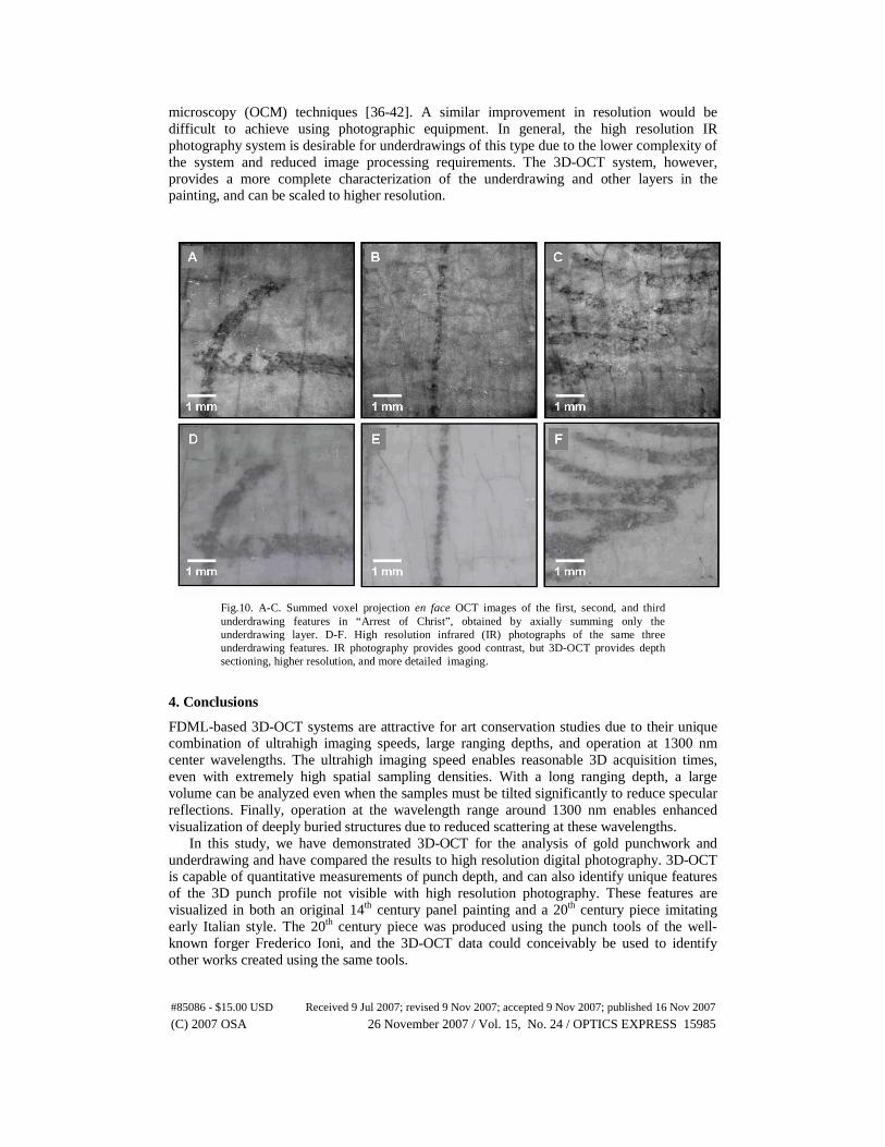
High resolution IR photography is also capable of visualizing the underdrawing layer with comparable XY resolution to the 3D-OCT system. Figure 10(A-C) shows summed voxel projection en face OCT images of the three underdrawing features. These en face images were generated by axial summation of the underdrawing layer only. Figure 10(D-F) shows high resolution IR photographs of the same underdrawing features. Although the photography system cannot achieve depth sectioning, the absorption properties of the underdrawing material and the overlying paint material are significantly different in the wavelength range of 900 – 1100 nm. This difference is more pronounced than at the OCT imaging wavelength of 1287 nm, which results in slightly higher contrast in the IR photography images.
The 3D-OCT data has slightly better transverse resolution than the photography system, and en face OCT images can be formed exclusively from the underdrawing layer. In comparison, the photography system integrates the signal returned by all layers of the painting, which tends to blur out fine details of the underdrawing microstructure. Therefore the 3D-OCT system is better suited for evaluating the fine details of the underdrawing microstructure and distinguishing liquid from solid underdrawing material. The granular nature of the underdrawing is more apparent in the 3D-OCT images in Fig. 10(A-C) than the IR photographs in Fig. 10 (D-F). Furthermore, the transverse resolution of the 3D-OCT system can readily be improved to 5 – 10 μm, or to < 5 μm using optical coherence
#85086 - $15.00 USD Received 9 Jul 2007; revised 9 Nov 2007; accepted 9 Nov 2007; published 16 Nov 2007
(C) 2007 OSA 26 November 2007 / Vol. 15, No. 24 / OPTICS EXPRESS 15984
microscopy (OCM) techniques [36-42]. A similar improvement in resolution would be difficult to achieve using photographic equipment. In general, the high resolution IR photography system is desirable for underdrawings of this type due to the lower complexity of the system and reduced image processing requirements. The 3D-OCT system, however, provides a more complete characterization of the underdrawing and other layers in the painting, and can be scaled to higher resolution.
Fig.10. A-C. Summed voxel projection en face OCT images of the first, second, and third underdrawing features in “Arrest of Christ”, obtained by axially summing only the underdrawing layer. D-F. High resolution infrared (IR) photographs of the same three underdrawing features. IR photography provides good contrast, but 3D-OCT provides depth sectioning, higher resolution, and more detailed imaging.
4. Conclusions
FDML-based 3D-OCT systems are attractive for art conservation studies due to their unique combination of ultrahigh imaging speeds, large ranging depths, and operation at 1300 nm center wavelengths. The ultrahigh imaging speed enables reasonable 3D acquisition times, even with extremely high spatial sampling densities. With a long ranging depth, a large volume can be analyzed even when the samples must be tilted significantly to reduce specular reflections. Finally, operation at the wavelength range around 1300 nm enables enhanced visualization of deeply buried structures due to reduced scattering at these wavelengths.
In this study, we have demonstrated 3D-OCT for the analysis of gold punchwork and underdrawing and have compared the results to high resolution digital photography. 3D-OCT is capable of quantitative measurements of punch depth, and can also identify unique features of the 3D punch profile not visible with high resolution photography. These features are visualized in both an original 14th century panel painting and a 20th century piece imitating early Italian style. The 20th century piece was produced using the punch tools of the well-known forger Frederico Ioni, and the 3D-OCT data could conceivably be used to identify other works created using the same tools.
#85086 - $15.00 USD Received 9 Jul 2007; revised 9 Nov 2007; accepted 9 Nov 2007; published 16 Nov 2007
(C) 2007 OSA 26 November 2007 / Vol. 15, No. 24 / OPTICS EXPRESS 15985
When comparing the visualization of underdrawing using 3D-OCT and high resolution IR photography, similar lateral resolution could be obtained with both techniques. En face OCT images of underdrawing can be formed from a specific painting layer, and do not require integration of the signal over the entire depth of the painting. Therefore, the microstructural characteristics of the underdrawing are more evident using 3D-OCT, and identification of the drawing medium may be enhanced using this approach. 3D-OCT also provides additional cross sectional information such as the location of the underdrawing layer within the painting. 3D-OCT can separate the underdrawing from IR-absorptive materials in the more superficial layers. However, for highly transparent paint layers, high resolution IR photography may be more suitable due to its comparable performance and lower complexity. IR photography also can image a larger field of view more rapidly than 3D-OCT.
In the future, we plan to study multiple works containing gold punches attributed to the same artist, and will attempt to determine whether or not the same tools were used to create each work. We will also study known and suspected forgeries, and will attempt to verify that different gold punch tools were used to create the forgeries than the authentic works. For the study of underdrawings, a systematic survey of underdrawing media and materials will help to asses the full potential of OCT to identify specific drawing techniques. Red and white drawing materials such as chalk could be imaged, although chalk has a refractive index (n = 1.486 – 1.66) similar to drying oils (n = 1.5) and may be difficult to detect. In cases such as Raphael’s “Garvagh Madonna”, where IR photography is unable to give a definite answer about the drawing material beneath the paint layers [43], 3D-OCT may advance our understanding about its creation. In general, 3D-OCT will improve the understanding of historical art work by enabling 3D microstructural examination without the need to remove material from the work in question.
Acknowledgements
This research was sponsored by the National Science Foundation BES-0522845 and ECS ECS-0501478, Air Force Office of Scientific Research FA9550-040-1-0046 and FA9550-040-1-0011. D.C.A. acknowledges financial support from the Natural Sciences and Engineering Research Council (NSERC) of Canada. J.S. acknowledges a post-doctoral fellowship from the Andrew W. Mellon Foundation. J.G.F. and R.H. receive royalties from intellectual property owned by MIT and licensed to LightLabs Imaging.
#85086 - $15.00 USD Received 9 Jul 2007; revised 9 Nov 2007; accepted 9 Nov 2007; published 16 Nov 2007
(C) 2007 OSA 26 November 2007 / Vol. 15, No. 24 / OPTICS EXPRESS 15986