46
Compatibility issues with BIM ANDREAS KULL Master of Science Thesis Stockholm, Sweden 2012

i
Compatibility issues with BIM
ANDREAS KULL
Master of Science Thesis Stockholm, Sweden 2012


Compatibility issues with BIM
Andreas Kull

©Andreas Kull, 2012
Royal Institute of Technology (KTH)
Department of Civil and Architectural Engineering
Stockholm, Sweden, 2012

i
Preface
A big thank you goes out to Sweco & KTH for making this report possible. And thanks to all
friends and family for your support.
Stockholm, December 2011
Andreas Kull


iii
Abstract
With the growing demand and use of BIM modeling, there’s also a growing number of
competitors. Since every provider of BIM software has their own specific functions and file
formats, there is no standard common platform and compatibility issues occur when projects
are transferred between each other.
Focus for this thesis is this gap and what can be done from preventing the gap to expand even
more, this will be done by having a look at the most promising solutions that exists today.
If a way to prevent this from happening is discovered, this will be documented in the report
and if possible, a program will be developed that can be used by anyone in order for the
programs to communicate with each other in a better way.
Keywords: BIM, C#, Tekla, Revit, IFC, SDNF, Programming


v
Sammanfattning
I och med att användandet av BIM-modellering ökar så ökar även antalet konkurrerande
företag. Eftersom varje företag har sin egen syn på specifika funktioner samt sina egna
filformat samt databasstruktur finns det ingen gemensam mark för ett standardformat. Detta
bidrar till att problem uppstår då man vill föra över projekt mellan olika program vilket sker i
de olika skedena av ett projekt.
Fokusen i detta examensarbete är centrerad runt detta problem och vad som kan göras för att
undvika att det i framtiden blir ännu större. I denna rapport kommer även dagens mest
lovande lösningar studeras
Om ett sätt att undvika vissa av dessa problem hittas, kommer detta dokumenteras samt ett
försök kommer göras att utveckla ett program som kan användas av vem som helst för att
programmen skall kunna kommunicera med varandra på ett bättre sätt
Nyckelord: BIM, C#, Tekla, Revit, IFC, SDNF, Programmering


vii
Contents
Preface ........................................................................................................................................ i
Abstract .................................................................................................................................... iii
Sammanfattning ....................................................................................................................... v
1 Introduction ...................................................................................................................... 1
1.1 Background ............................................................................................................. 1
1.1.1 Building Information Modeling (BIM) ...................................................... 1
1.2 Purpose .................................................................................................................... 3
1.3 Workflow ................................................................................................................. 3
1.4 Limitations ............................................................................................................... 3
2 Terminology ..................................................................................................................... 5
2.1 Hexadecimal representation .................................................................................... 5
2.2 GUID (Globally Unique Identifier) ......................................................................... 6
2.3 Reason for using GUID ........................................................................................... 6
3 The programs ................................................................................................................... 9
3.1 Revit ........................................................................................................................ 9
3.1.1 General ....................................................................................................... 9
3.1.2 Revit and IFC ............................................................................................. 9
3.1.3 Program structure ....................................................................................... 9
3.1.4 IFC export ................................................................................................ 10
3.1.5 Revit extensions ....................................................................................... 11
3.2 Tekla Structures ..................................................................................................... 12
3.2.1 General ..................................................................................................... 12
3.2.2 Tekla and IFC ........................................................................................... 12
3.2.3 Program structure ..................................................................................... 12
3.2.4 IFC export ................................................................................................ 12
3.3 .NET Framework ................................................................................................... 13

viii
3.3.1 General ..................................................................................................... 13
3.3.2 C# ............................................................................................................. 13
3.4 API ......................................................................................................................... 14
3.4.1 Revit API .................................................................................................. 14
3.4.2 Tekla API ................................................................................................. 16
4 Alternative routes .......................................................................................................... 17
4.1 IFC ......................................................................................................................... 17
4.1.1 General ..................................................................................................... 17
4.1.2 Why IFC ................................................................................................... 17
4.1.3 Troubleshooting ....................................................................................... 18
4.1.4 Components of IFC .................................................................................. 18
4.1.5 IFC GUID ................................................................................................. 21
4.2 Steel detailing neutral format (SDNF) .................................................................. 26
5 Results ............................................................................................................................. 27
6 Conclusion ...................................................................................................................... 30
Bibliography ........................................................................................................................... 31

1
1 Introduction
The current market is still in an embryo stage when referring to the BIM-effort (Building
Information Modeling). There isn’t really any common ground for architects, civil engineers
and other entrepreneurs because of the variety of different BIM software that is used for
different purposes.
For instance, the civil engineers are using programs such as Tekla, which emphasizes more on
detailing in a model, while architects uses Revit that emphasizes more on a more realistic
model with surroundings, but in general they work the same way.
This creates a gap since Revit and Tekla has different program structure compared to each
other. With this gap, many of the advantages with BIM are lost, mostly the intelligence of the
model that is unique for the BIM environment. Intelligence means more or less that the model
has information about every object and element and this intelligence makes all the unique
functions in a BIM environment possible.
The closest to a complete and error-free solution that exists today is the IFC (Industry
Foundation Classes) format, which is an open source attempt towards interoperability, but
unfortunately, problems appear when using this format.
1.1 Background
1.1.1 Building Information Modeling (BIM)
General
There’s a major difference in-between the way pre-BIM programs works compared to BIM
programs, not just in the user interface (UI) but also in the way the programs are working.
The ‘old’ programs such as AutoCAD are using a geometric model where lengths,
coordinates, widths and such are specified. The object doesn’t contain any information except
its geometry and its layer.
BIM is all about the information one can extract from a model.

2
Definition
Building information modeling can cover almost every aspect of a building. Information is
easy to extract, such as quantities, materials, heights, geographic information, bolts etc.
Views, sections, 3D models and so on can generated in a very short amount of time compared
to how they used to be, this is because they are all based on one model. Since there are a lot
of changes and updates during a project, this eliminates a lot of repetition in a work aspect
and if a object is adjusted in one view, it gets automatically adjusted in all the other views
where the object is visible
Data models
In a BIM-Environment object based data models are used. This means every object or
element is represented by an ID number, this ID number is paired with a set of instructions
that describes the geometry and also other data associated with the object.
The intelligent data already contains the geometry of for instance the steel beam, and what
needs to specified is just the start and the end of the beam (in a X Y Z-plane)
In a Geometric data model, the data can be represented with an origin point, a length and a
width.
In a Building data model many extra parameters can be applied, such as types, areas,
connected elements.
Figure 1 – The difference between Geometric and Building data models (www.aecbytes.com)

3
1.2 Purpose
The purpose of this master thesis is to eliminate the repetition of workload that is obvious in
today’s market. An outcome such as a refined export/import in-between Tekla and Revit
would be ideal, which would mean that less data is lost in the transfer and the model to be
kept as close as possible to intact. An enhanced understanding of the IFC-format and the
general BIM-format is necessary for further and future development towards interoperability.
1.3 Workflow
The documentation on the Tekla and Revit API will be studied thoroughly during this thesis,
this documentation gives the user better understanding of how the programs are built (from a
programming perspective). In order to understand the API documentation understanding of
.NET Framework is needed which is a collection of programming languages (explained in
detail later).
1.4 Limitations
All the problems experienced can’t be solved at the same time, therefore the first problem to
focus on will be a performance issue when working with models with lots of steel elements.
There is a wide variety of problems occurring when the connection between Tekla and Revit
isn’t working, since the intelligence of the model isn’t kept, the possibilities of modification
of the elements are limited. One of these problems is the detail level, which sets the detail of
the model. In a working model, this can easily be adjusted because of the structure of the
database. For every element there are 3 different versions in terms of visibility, showing
different amount of element details. These details can be material visibility, shading, radiuses
shown in the element and so on. This has a major impact on bigger models, performance
wise, and it cannot be adjusted when importing an IFC file from Tekla to Revit. Since a
complete rewrite of the export or import function would have to be done in order to solve all
the problems, the detail level will be the first priority in this thesis. See Figure 1 compared to
Figure 2.

4
Figure 2 - Detail Level - Fine
Figure 3 - Detail Level - Medium

5
2 Terminology
In the following chapter some of the terminology that are used in this report are explained, the
reader should at least be familiar with these terms.
2.1 Hexadecimal representation
One bit, is represented by 2 relays: 1 or 0
One byte is represented by 8 bits, therefore each digit in the GUID above is represented by 16
bits or 2 bytes.
Hex Dec Binary
0 0 0 0 0 0
1 1 0 0 0 1 2 2 0 0 1 0 3 3 0 0 1 1 4 4 0 1 0 0 5 5 0 1 0 1 6 6 0 1 1 0 7 7 0 1 1 1 8 8 1 0 0 0 9 9 1 0 0 1 A 10 1 0 1 0 B 11 1 0 1 1
C 12 1 1 0 0 D 13 1 1 0 1 E 14 1 1 1 0
F 15 1 1 1 1
This is called hexadecimal representation, with a 16 base. For instance the number 27 would
be represented with the number ‘1a’. In this thesis the reader doesn’t have to go too much into
detail regarding the binary level, the reader should only know that it exists in order to
understand the basics of a HEX-number.
Since every digit in the hexadecimal and decimal system is represented by 4 binary digits, the
32 characters in the GUID above is a 32*4= 128 bit number.

6
Every bit can be either 1 or 0 which gives a variation of 2^128 (or 10^38) numbers. For
instance the number ‘15 847 451’ would be represented with ‘f1d01b’
There are many thousands of objects (ID-numbers) in a BIM-environment and new objects
are constantly created there has to be a way to manage all these numbers.
2.2 GUID (Globally Unique Identifier)
A GUID is an ID number that is unique, they are used in many databases for identifying
objects and they are used also in a both Revit and Tekla for identifying elements. GUIDs are
usually represented by a 128-bit (see explanation below) number; they typically look like:
60f91daf-3dd7-4283-a86d-24137b73f3da
2.3 Reason for using GUID
When a new object is created, for instance for a new family group member, instead of
requesting a number from the general object based data model and waiting to get a unique
number, a unique number is created purely relying on statistics since the risk of getting a
GUID that is already used in slim to 0 percent.
GUID generation algorithms is today a standard for identifying an object in many framework
environments
The whole coordination process is also avoided with this method, which would be very
problematic with many new numbers requested continuously. These ID numbers are not just
used in the world of BIM in more or less everything that is stored in a database.
Below is an example of how a GUID generator works, note that this is just a proof of concept
and that there’s already a ready function for converting an integer to a hexadecimal base. This
program could also be used instead for another base for instance if it was modified a bit.

7
Figure 4 – Example of a GUID calculator


9
3 The programs
3.1 Revit
3.1.1 General
Revit is working with their own format (.RVT), each user is working with is a standalone
database file. The user can setup views, sections, elevations and so forth, and when something
is changed in the model, it’s represented in all of the views of the model. Models can also be
shared over the LAN (Local Area Network) of the user and each model can be worked on
simultaneously, this is possible by creating a central file.
The user can extrude, trim, extend objects in 2D into 3D objects.
3.1.2 Revit and IFC
Revit is certified for IFC2x2 and IFC2x3, which means that the developers of the IFC format
considers that their product is compatible (working as it should).
3.1.3 Program structure
Revit uses a number of ID numbers in order to identify its objects, for instance when a wall is
created the following IDs are generated
Element ID
Is a 6-digit ID, This number is unique only within the current project.
Episode ID
The GUID number is unique for each object type, for instance if several HEA200 beams are
generated, they will have the same GUID number, the episode ID is a GUID number.
Unique ID
EpisodeID + ElementID, functions like a GUID and is unique across all Revit projects. This
ID is what keeps track of the objects when exported to other formats (API 2012 Developer
Guide, Autodesk). The Unique ID is very simple to fetch from within the API.

10
Families
Families are the basic foundation of Revit, in order to avoid each model to be too heavy with
information, Revit introduced families. An example of a family is a HEA beam, if the user
choses to import a HEA family the type of HEA beam will also be chosen, for instance
HEA300.
The user loads the information contained in the family files (.RFA) as they are creating their
model, and only importing the necessary objects into the model. Each company can tailor
their own families according to their own (or the countries) needs or standards.
There are two categories of families:
Figure 5 – Taken from the Autodesk API Developer Guide
The System Families – The system families enables the user to create their
own elements.
The Component Families – These families are neither for creation nor manual
loading, instead they are predefined by Revit.
Examples are dimensions, levels, roofs, floors.
3.1.4 IFC export
When exporting to IFC from Revit though, these IDs generates into a GUID. Revit reads each
object as a geometry and creates a new family, the problem with this family is the properties.
The user can’t change the family type or any of its properties.
It uses the local coordinates, by first defining a parameter called ‘IFC local placement’, this
which refers to the center point of the object/element. The local coordinates as mentioned
before consists of coordinates in an X and Y plane. The Z coordinates is only defined as the
center point of the element and can be thought of as an extrusion of the 2-dimensional
element.
After the local coordinate for the object or element center is defined, points are defined; called
‘IFC Cartesian Points’. These points are tied together by ‘IFC polyline’, referring in between
two points.
This polyline is later converted into an ‘IFC composite curve segment’.
Curves (radiuses) is handled a bit different, they are defined by ‘IFC Cartesian points’, the
point is in the center of a circle, this circle gets trimmed with the command ‘IFC trimmed
curve’, for instance in between 90 and 180 degrees, which makes a quarter of a circle which

11
represents the radius in an element. The trimmed curved finally gets converted to ‘IFC
composite curve segment’ as well.
When all the parts of the element have been defined, the segments are with using the
command ‘IFC composite curve’ and referring to all the line numbers of the containing parts.
The polylines must be extended according to the radius removed for this method to work
correctly.
3.1.5 Revit extensions
Revit extensions is an external add-on package for Revit, it implements several new functions
trough macros

12
3.2 Tekla Structures
3.2.1 General
Tekla Structures is aiming towards detailing more than Revit. Tekla is compatible with many
different formats. The detailing is greater and deeper in detail compared to Revit, the user is
able to model bolts, welds, base plates, anchor rods, details in stairs. This precession of
detailing is needed for civil engineers many civil engineers. Macros and other add-ins is used
a lot in Tekla since many details are very much customizable.
Models can be shared just as in Revit.
3.2.2 Tekla and IFC
Tekla uses a slightly different way of writing IFC files compared to Revit, the program is
certified for compatibility with both IFC2x2 and IFC2x3.
3.2.3 Program structure
Tekla uses a database and identifies its objects with GUID numbers, similar to the way Revit
uses its ID numbers. The program is not divided the same way with families though.
3.2.4 IFC export
The export from Tekla works with a different set of tools compared to Revit, the format is
more efficient and easier to modify but it has less possibilities of unique modification.
IFC as a format contains family like components. An example of this is
IFCISHAPEPROFILEDEF which represent a normal H-type of beam where the user can
specify all the properties of the element, for instance an entry can look like the following:
#3645= IFCISHAPEPROFILEDEF(.AREA.,'HEA200',#3642,200.,190.,6.5,10.,18.);
This represents all the data for the type such as height, width, flange thickness, radius etc.
13
3.3 .NET Framework
The .NET Framework is the foundation for understanding how Revit and Tekla works on a
program level.
3.3.1 General
.NET Framework is provided by Microsoft, it’s an object oriented language and reminds of
C++, the framework is less advanced though when focusing on memory management for
instance, which is not necessary for applications as simple as add-ins/macros for programs
such as Revit and Tekla. The framework consists of three different languages: C# (C Sharp),
VB (Visual Basic) and J# (J Sharp)
The advantage with .NET is the wide spectra of use. It uses only is the Common Language
Runtime (CLR), in other words only in an software environment, it also contains a wide and
efficient Base Class Library containing many numerical algorithms, UI, operators and so on.
3.3.2 C#
Most of the applications used in the engineering and architect companies are used in a
Windows environment, this allows for modification trough a .Net-language. C# (C-Sharp),
VB and J# all compiles to the same Common Language Infrastructure (CLI), so any of them
can be used for writing macros/plug-ins for Tekla and Revit. The API documentation though
only covers C# and VB.
For both Tekla and Revit the user/programmer has to compile the files into .DLL-files in
order to be used as a plug in.
In C# the programmer can also develop standalone applications which can be used externally.

14
3.4 API
Application Programming Interface (API), is a source code interface, it’s the link between the
programs source code and its libraries and it’s used to develop add-ins and macros for the
program or automation of other processes. Using the API though doesn’t give the developer
rights to develop whatever they want, instead this is limited by the provider of the API. This
means that there are specific commands that are allowed by the API in order to automate
some processes, but not the core of the program.
When developing trough the API in C#, the process is connected to the main program which
gives the developer the possibilities of real time debugging and a more general control over
the process since C# is very stable in a debugging perspective.
If the API wouldn’t contain any restrictions, this would be the most effective solution, it
would mean that the export is handled without any middle hand (such as IFC), this way the
data exported/imported could be tailored not to export unnecessary information. Maybe
linking two projects could even be possible. The downside is that it has to be coded from
scratch. This alterative would need a great amount of time to be accomplished, and studying
of the both APIs would have to be done.
3.4.1 Revit API
Autodesk allows their end users to develop within their own API, providing a 500 page API
manual, downloadable from their own website for anyone to write own macros and add-ins.
There are limitations of the API though, since Autodesk does not want developers to alternate
their software too much.
Autodesk has released an open source documentation of the IFC export function, but not the
import.
According to Autodesk you can use the Revit Platform API to (Revit 2012 API Developer
Guide, Autodesk):
Gain access to model graphical data.
Gain access to model parameter data.
Create, edit, and delete model elements like floors, walls, columns, and more.
Create add-ins to automate repetitive tasks.
Integrate applications into Revit-based vertical products. Examples include
linking an external relational database to Revit or sending model data to an
analysis application.
Perform analysis of all sorts using BIM.
Automatically create project documentation

15
Example code
Above is a simple code example for fetching the element-id. When debugging this piece of
code, Revit opens and the add-in is loaded as a macro. The user can highlight a couple of
elements and then run the add-in from Revit. This results in a message box showing the IDs
of the elements the user has highlighted, the picture below shows the result of one successful
run of this program (Jeremy Tammik, Autodesk).

16
3.4.2 Tekla API
Tekla Structures provides an online database API, it contains the basic commands but no
example code.
The limit of this thesis is actually the possibilities and limitations of the API and also how
well documented the SDK is. The privileges given to developers within programs are often
limited in the sense that you can’t access all the functions of the main program. Unfortunately
the support from Tekla Structures weren’t enough to get a good understanding of the API

17
4 Alternative routes
The limitations are actually being set by the limitations of the API’s and the IFC-format itself.
Of course the limited time in this thesis is also a factor.
4.1 IFC
4.1.1 General
The IFC format was created with the sole purpose to address the interoperability in today’s
market. A couple of years ago IFC was firstly implemented from a clean install of Revit and
Tekla, before it was only implemented through the API as an external plugin. Both Autodesk
and Tekla claim full compatibility. To understand the format one first needs to understand
how Revit and Tekla are working.
4.1.2 Why IFC
There are many different formats at the market today, the big corporations are aiming for
pushing their own format with the towards a monopoly while the smaller companies has a
bigger urge to be a part of the process too, therefore pushing more towards interoperability.
Of the open source-formats that exist at the present time, IFC is considered to be the most
complete.
18
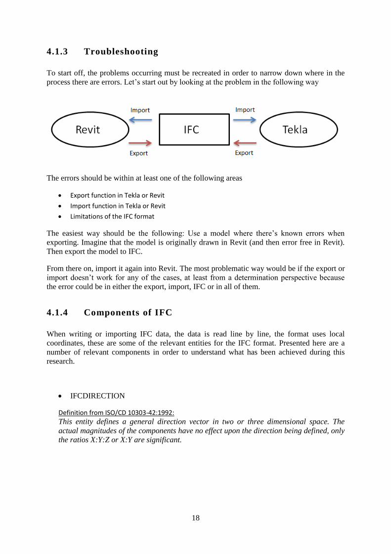
4.1.3 Troubleshooting
To start off, the problems occurring must be recreated in order to narrow down where in the
process there are errors. Let’s start out by looking at the problem in the following way
The errors should be within at least one of the following areas
Export function in Tekla or Revit
Import function in Tekla or Revit
Limitations of the IFC format
The easiest way should be the following: Use a model where there’s known errors when
exporting. Imagine that the model is originally drawn in Revit (and then error free in Revit).
Then export the model to IFC.
From there on, import it again into Revit. The most problematic way would be if the export or
import doesn’t work for any of the cases, at least from a determination perspective because
the error could be in either the export, import, IFC or in all of them.
4.1.4 Components of IFC
When writing or importing IFC data, the data is read line by line, the format uses local
coordinates, these are some of the relevant entities for the IFC format. Presented here are a
number of relevant components in order to understand what has been achieved during this
research.
IFCDIRECTION
Definition from ISO/CD 10303-42:1992:
This entity defines a general direction vector in two or three dimensional space. The
actual magnitudes of the components have no effect upon the direction being defined, only
the ratios X:Y:Z or X:Y are significant.
19
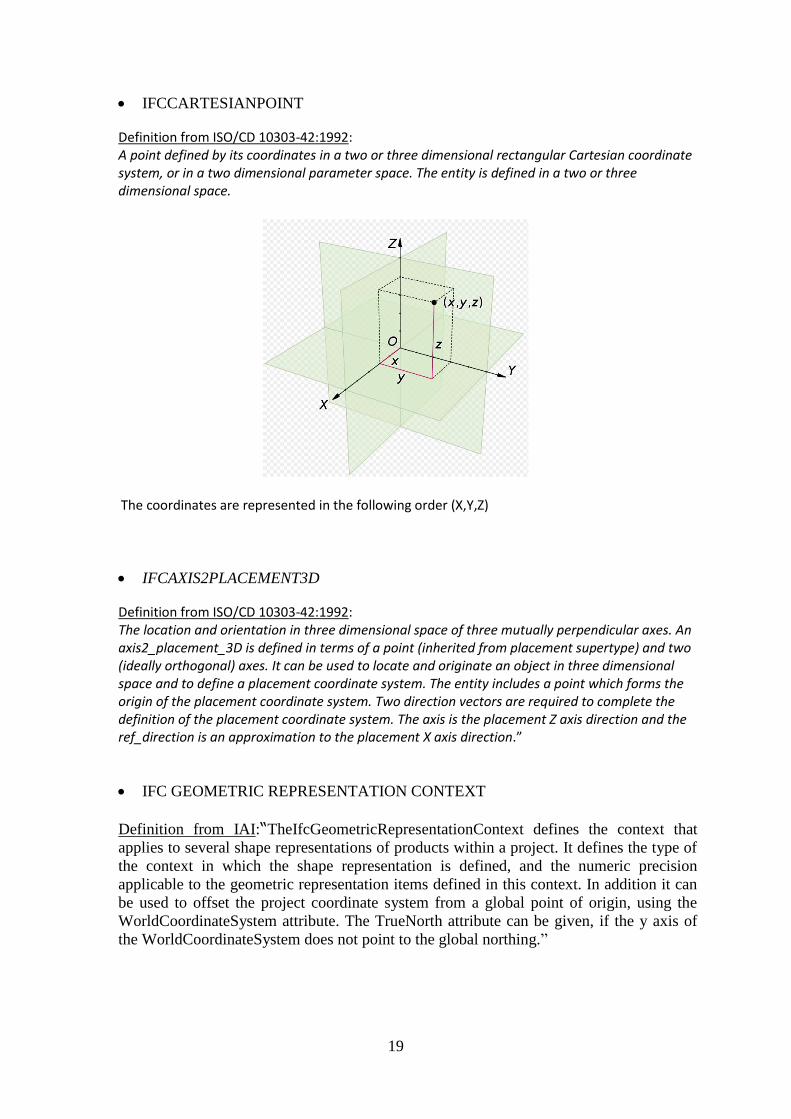
IFCCARTESIANPOINT
Definition from ISO/CD 10303-42:1992: A point defined by its coordinates in a two or three dimensional rectangular Cartesian coordinate system, or in a two dimensional parameter space. The entity is defined in a two or three dimensional space.
The coordinates are represented in the following order (X,Y,Z)
IFCAXIS2PLACEMENT3D
Definition from ISO/CD 10303-42:1992: The location and orientation in three dimensional space of three mutually perpendicular axes. An axis2_placement_3D is defined in terms of a point (inherited from placement supertype) and two (ideally orthogonal) axes. It can be used to locate and originate an object in three dimensional space and to define a placement coordinate system. The entity includes a point which forms the origin of the placement coordinate system. Two direction vectors are required to complete the definition of the placement coordinate system. The axis is the placement Z axis direction and the ref_direction is an approximation to the placement X axis direction.”
IFC GEOMETRIC REPRESENTATION CONTEXT
Definition from IAI:“TheIfcGeometricRepresentationContext defines the context that
applies to several shape representations of products within a project. It defines the type of
the context in which the shape representation is defined, and the numeric precision
applicable to the geometric representation items defined in this context. In addition it can
be used to offset the project coordinate system from a global point of origin, using the
WorldCoordinateSystem attribute. The TrueNorth attribute can be given, if the y axis of
the WorldCoordinateSystem does not point to the global northing.”
20
IFC POLYLINE
Definition from ISO/CD 10303-42:1992: An IfcPolyline is a bounded curve of n -1 linear segments, defined by a list of n points, P1, P2 ... Pn. The curve is parameterized as follows:
for 1 i n - 1, where i -1 u i and with parametric range of 0 u n - 1.
IFC SHAPE REPRESENTATION
Definition from IAI: The IfcShapeRepresentation represents the concept of a particular geometric representation of a product or a product component within a specific geometric representation context. The inherited attribute RepresentationType is used to define the geometric model used for the shape representation, the inherited attribute RepresentationIdentifier is used to denote the part of the representation captured by the IfcShapeRepresentation (e.g. Axis, Body, etc.).
IFCCOMPOSITECURVESEGMENT
Definition from ISO/CD 10303-42:1992: “A composite curve segment (IfcCompositeCurveSegment) is a bounded curve together with transition information which is used to construct a composite curve (IfcCompositeCurve). “
IFCCIRCLE
Definition from ISO/CD 10303-42:1992: “An IfcCircle is defined by a radius and the
location and orientation of the circle. Interpretation of data should be as follows: “
"A circular arc is defined by using the trimmed curve (IfcTrimmedCurve) entity in
conjunction with the circle (IfcCircle) entity as the BasisCurve.“
IFCTRIMMEDCURVE
Definition from ISO/CD 10303-42:1992: A trimmed curve is a bounded curve which is
created by taking a selected portion, between two identified points, of the associated basis
curve. The basis curve itself is unaltered and more than one trimmed curve may reference
the same basis curve. Trimming points for the curve may be identified by:
o parametric value
o geometric position
o both of the above
At least one of these shall be specified at each end of the curve. The SenseAgreement
makes it possible to unambiguously define any segment of a closed curve such as a circle.
The combinations of sense and ordered end points make it possible to define four distinct
directed segments connecting two different points on a circle or other closed curve. For
this purpose cyclic properties of the parameter range are assumed; for example, 370
degrees is equivalent to 10 degrees.
21
4.1.5 IFC GUID
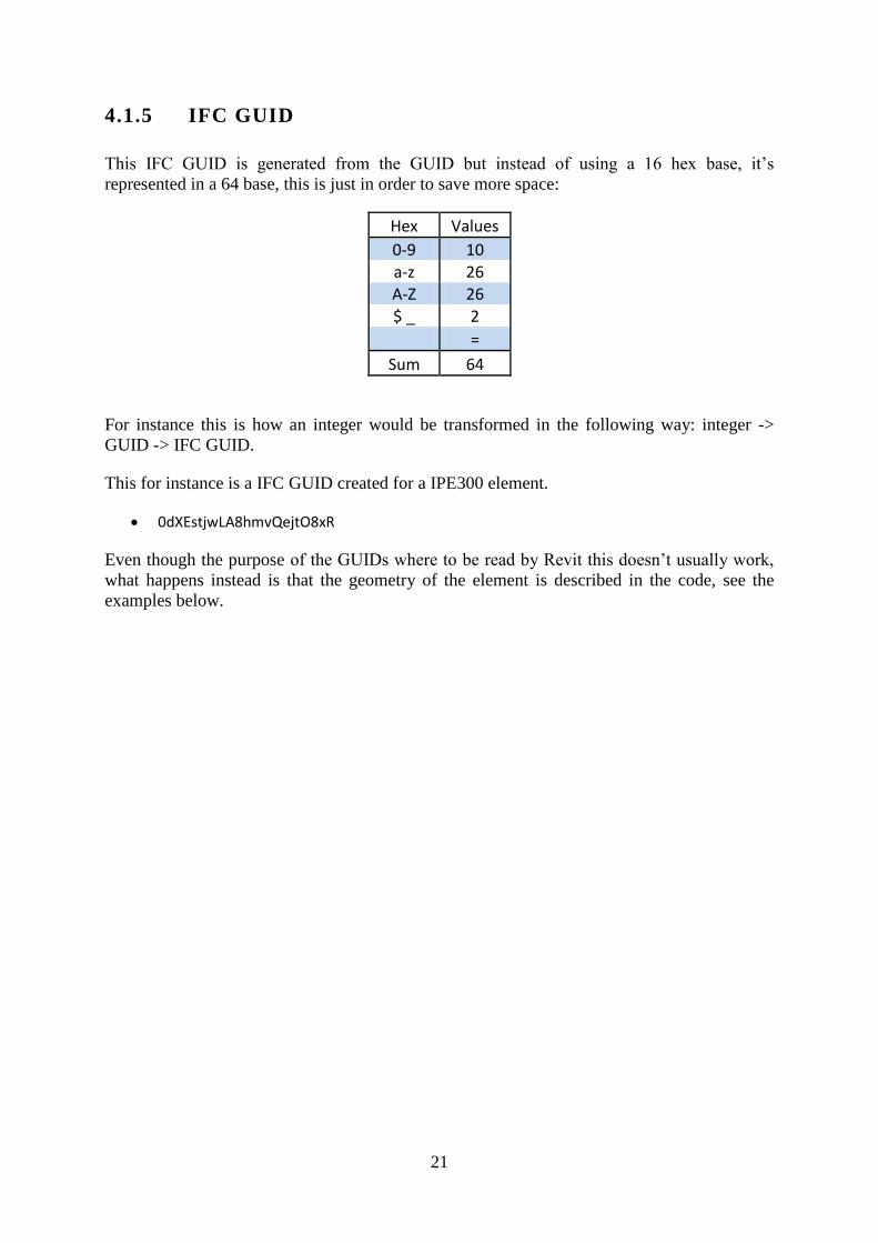
This IFC GUID is generated from the GUID but instead of using a 16 hex base, it’s
represented in a 64 base, this is just in order to save more space:
Hex Values
0-9 10 a-z 26 A-Z 26 $ _ 2
=
Sum 64
For instance this is how an integer would be transformed in the following way: integer ->
GUID -> IFC GUID.
This for instance is a IFC GUID created for a IPE300 element.
0dXEstjwLA8hmvQejtO8xR
Even though the purpose of the GUIDs where to be read by Revit this doesn’t usually work,
what happens instead is that the geometry of the element is described in the code, see the
examples below.

22
Example 1 - Polylines
For instance, from the code snippet given before this chapter it may be represented this way, this snippet is from part of a HEA200 beam.
#3=IFCCARTESIANPOINT((0.,0.,0.)); #4=IFCCARTESIANPOINT((0.,0.)); #26=IFCAXIS2PLACEMENT3D(#3,$,$); #27=IFCGEOMETRICREPRESENTATIONCONTEXT($,'Model',3,1.E-006,#26,$); #48=IFCCARTESIANPOINT((-0.,12000.)); #49=IFCPOLYLINE((#4,#48)); #50=IFCSHAPEREPRESENTATION(#27,'Axis','Curve2D',(#49));
Why are all these specific lines given in the example? Take a look at entry #50 and look at its references, that way the user can back trace all the relevant entries. This is what happens:
A coordinate in 3 dimensions is defined (#3)
A coordinate in 2 dimensions is defined (#4)
The axis reference plane is set the same way as entry #3
The geometric representation is in 3 dimensions.
A coordinate in 2 dimensions is defined (#48)
A polyline vector is created in between the 2 two-dimensional points.
The shape representation is defined with the geometric representation as a base, Axis and in a 2 dimensional space applies to the polyline.
To sum these rows up they would draw a 12 m polyline
Example 2 - Circles
#11=IFCDIRECTION((1.,0.)); #70=IFCCARTESIANPOINT((30.24999999999962,-58.)); #71=IFCAXIS2PLACEMENT2D(#70,#11); #72=IFCCIRCLE(#71,27.); #73=IFCTRIMMEDCURVE(#72,(IFCPARAMETERVALUE(179.9999999999999)),(IFCPARAMETERVALUE(269.9999999999997)),.T.,.PARAMETER.); #74=IFCCOMPOSITECURVESEGMENT(.CONTINUOUS.,.F.,#73); #75=IFCCARTESIANPOINT((3.249999999999261,-58.)); #76=IFCCARTESIANPOINT((3.249999999999261,58.));
Entry # 72 states that the radius is 27 mm, in entry #70 this makes sense since 7/2 + 27 =
30.25. -58 is because -190/2+10+27= -58.
These lines would draw a circle and trim it in the downright corner of the element.
23
Example 3
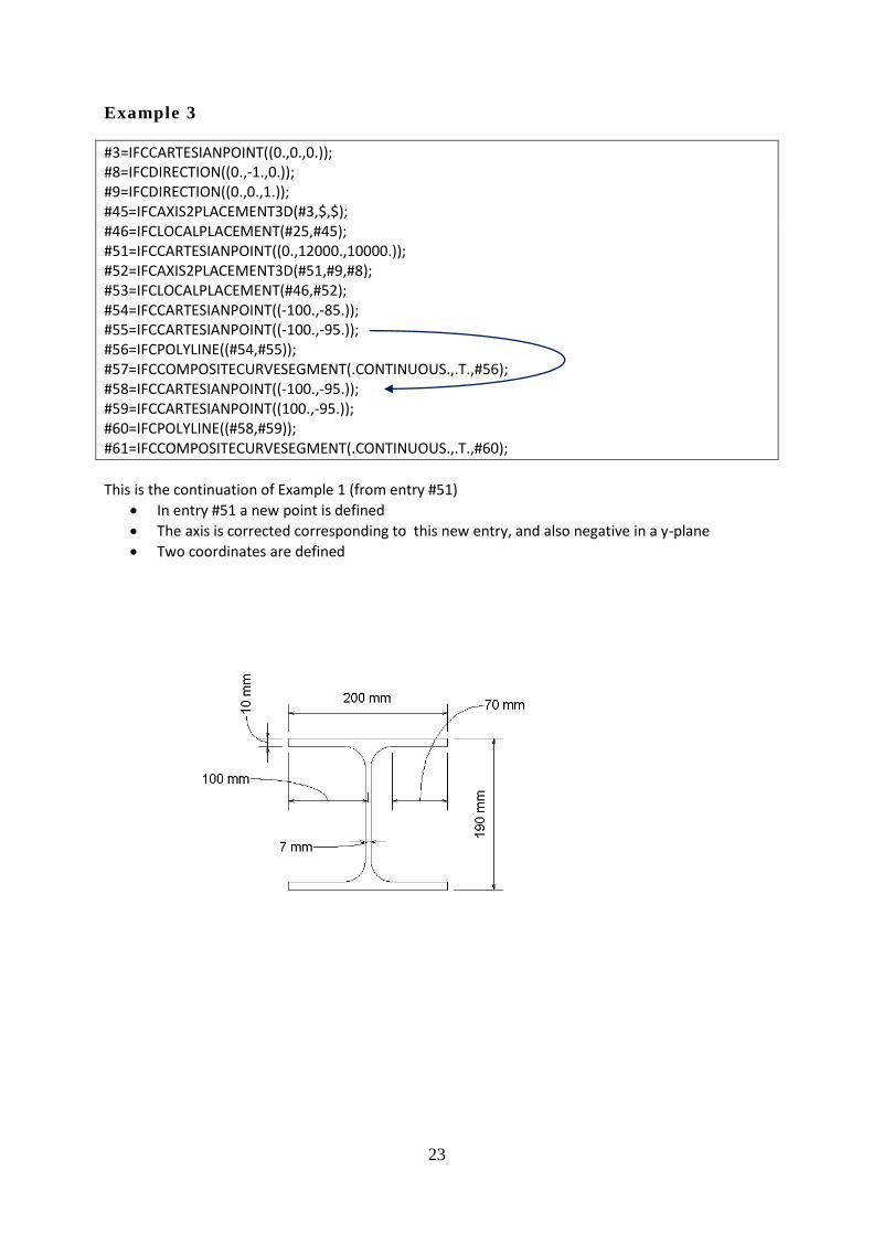
#3=IFCCARTESIANPOINT((0.,0.,0.)); #8=IFCDIRECTION((0.,-1.,0.)); #9=IFCDIRECTION((0.,0.,1.)); #45=IFCAXIS2PLACEMENT3D(#3,$,$); #46=IFCLOCALPLACEMENT(#25,#45); #51=IFCCARTESIANPOINT((0.,12000.,10000.)); #52=IFCAXIS2PLACEMENT3D(#51,#9,#8); #53=IFCLOCALPLACEMENT(#46,#52); #54=IFCCARTESIANPOINT((-100.,-85.)); #55=IFCCARTESIANPOINT((-100.,-95.)); #56=IFCPOLYLINE((#54,#55)); #57=IFCCOMPOSITECURVESEGMENT(.CONTINUOUS.,.T.,#56); #58=IFCCARTESIANPOINT((-100.,-95.)); #59=IFCCARTESIANPOINT((100.,-95.)); #60=IFCPOLYLINE((#58,#59)); #61=IFCCOMPOSITECURVESEGMENT(.CONTINUOUS.,.T.,#60);
This is the continuation of Example 1 (from entry #51)
In entry #51 a new point is defined
The axis is corrected corresponding to this new entry, and also negative in a y-plane
Two coordinates are defined

24
Example 4
#3645= IFCISHAPEPROFILEDEF(.AREA.,'HEA200',#3642,200.,190.,6.5,10.,18.);
This is an object exported from Tekla, it describes the element in an different way. All
element data is described in this single line: Width, height, flange thickness, web thickness &
radius, therefore the algorithm to change the code is very simple compared to a Revit
exported object.
Example 5 – Proof of concept
Now that the basic parameters have been explained, here’s a snippet of the IFC code for an HEA200 beam. In bigger projects the models tend to become too “heavy” with information and the model has to be separated into several smaller models in order to be able to handle them. The steel in the model can be simplified by not showing the radius between the flange and the web of the beam by adjusting the detail level. When exporting to IFC this detail cannot be adjusted. This method was invented by the author with only help from the Building Smart documentation
#170=IFCPROPERTYSINGLEVALUE('B',$,IFCLENGTHMEASURE(200.),$); #171=IFCPROPERTYSINGLEVALUE('H',$,IFCLENGTHMEASURE(190.),$); #172=IFCPROPERTYSINGLEVALUE('r',$,IFCLENGTHMEASURE(27.),$); #173=IFCPROPERTYSINGLEVALUE('t',$,IFCLENGTHMEASURE(10.),$); #174=IFCPROPERTYSINGLEVALUE('s',$,IFCLENGTHMEASURE(6.500000000000001),$); #175=IFCPROPERTYSINGLEVALUE('A',$,IFCAREAMEASURE(5383.),$);
Above is the cross section data, these are not used directly for creating the family but instead
used to import profile data for the type. Revit creates a new family with the same name as the
one exported instead of using one from their own database
#70=IFCCARTESIANPOINT((30.24999999999962,-58.)); #71=IFCAXIS2PLACEMENT2D(#70,#11); #72=IFCCIRCLE(#71,27.); #73=IFCTRIMMEDCURVE(#72,(IFCPARAMETERVALUE(179.9999999999999)),(IFCPARAMETERVALUE(269.9999999999997)),.T.,.PARAMETER.); #74=IFCCOMPOSITECURVESEGMENT(.CONTINUOUS.,.F.,#73);
These lines can be completely removed, they are parameters for a curve representing the
radius of the element.

25
#67=IFCCARTESIANPOINT((30.24999999999745,-85.)); #75=IFCCARTESIANPOINT((3.249999999999261,-58.)); #122=IFCCOMPOSITECURVE((#57,#61,#65,#69,#74,#78,#83,#87,#91,#95,#99,#103,#108,#112,#117,#121),.F.);
These lines needs to be modified, line #67 and #75 needs to be of the same value in at least
one direction, after adjusting these for one corner it looks like this when importing in Revit.
Line #122 also needs to be modified, as seen earlier the removed IFCCURVESEGMENT
needs to be removed, in this case #74.
Figure 6 – After the adjustment above

26
4.2 Steel detailing neutral format (SDNF)
There is an extension pack that can be installed for both Tekla and Revit, it contains several
macros and add-ins. SDNF is an alternative to IFC and in some ways it works much better
than IFC.
The user has to do manual mapping of the files, which are saved into a database for future
reference.
This way the intelligence of the model is kept, most elements are exported without any errors.
27
5 Results
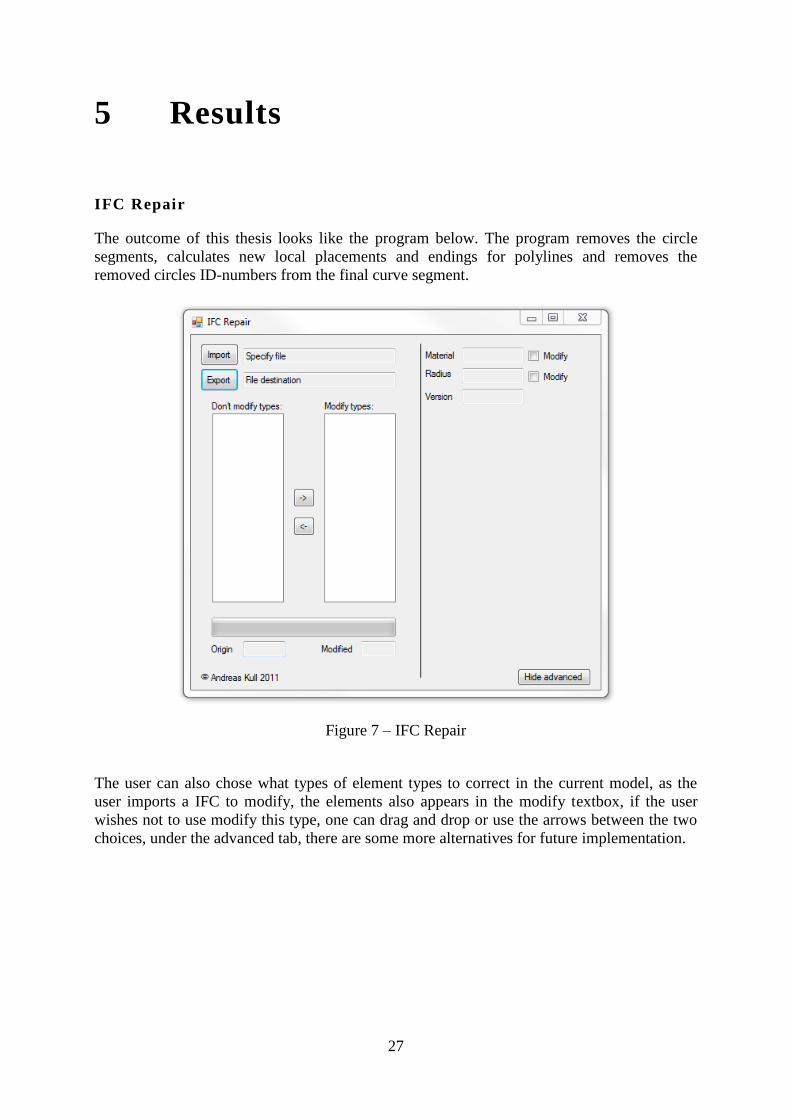
IFC Repair
The outcome of this thesis looks like the program below. The program removes the circle
segments, calculates new local placements and endings for polylines and removes the
removed circles ID-numbers from the final curve segment.
Figure 7 – IFC Repair
The user can also chose what types of element types to correct in the current model, as the
user imports a IFC to modify, the elements also appears in the modify textbox, if the user
wishes not to use modify this type, one can drag and drop or use the arrows between the two
choices, under the advanced tab, there are some more alternatives for future implementation.

28
Figure 8 – File opened in IFC repair
The user also gets notified trough a progress bar about the process and also how many
elements that has been modified. Usually this process isn’t very time consuming. Scanning
and adjusting a Tekla export is always faster than a Revit export since they use different
algorithms for adjustment.
The program consists of approximately 1500 lines of C# code and can be used in a windows
environment.
After using this algorithm and opening the project in Revit, the detail level is shown as
medium level in Revit and the radius of the elements doesn’t show. When the user exports
this format into a DWG format, there’s a major difference in the size of the files. The file size
is reduced with 70% in a model with lots of steel.
Different tests with the model such as zooming and turning the model and improvement in
speed was noticed (about 10 % faster) in a big model where 1700 elements were modified.

29
Figure 9 – Modified
Figure 10 - Not modified

30
6 Conclusion
Solving a problem of this width takes time, there isn’t any complete solution that solves all
the problems that exist today. What was done in this thesis was to adjust the detail level
(radiuses) of objects and elements in order to avoid the model from being too slow to manage,
but the results showed something else. There wasn’t and noticeably improvement in neither
the Tekla or Revit model. The exported DWG models showed a little bit of better
performance and file size was decreased with as much as 70%. In theory though, in even
bigger models this will have a impact on the performance.
The API for both Tekla and Revit was also studied, but unfortunately this alternative turned
out to be too time consuming and limited to be done.
If the GUID numbers would have been used in a different way, they would be ideal for
interoperability.
With the new IFC 2x4 around the corner hopefully the problems will be addressed in a new
way, the intelligence of the model will have to be kept in order for interoperability to be
enhanced, maybe this will come together with a new way of mapping, similar to the way
SDNF works today.
Developing of ‘IFC Repair’ could continue after the thesis since it has a potential into further
understanding the format until the point that some superior format, or update, is released.
What has been done in ‘IFC Repair’ is to modify the export of IFC, while the ultimate
solution would involve writing a new import function and using a mapping function to ensure
that no data is lost.

31
Bibliography
1\ Solis, M., Daniel., 2001. Illustrated C# 2010. APRESS, Vol. 79, pp.
2645-2662.
2\ Revit 2012 API, Developers guide, Autodesk
http://www.aecbytes.com/feature/2004/IFCmodel.html (2011-06-13)
http://en.wikipedia.org/wiki/Application_programming_interface (2011-06-14)
http://en.wikipedia.org/wiki/Building_Information_Modeling (2011-06-14)
http://redbolts.com/blog/post/2010/05/20/IFC-has-no-place-in-your-Revit-BIM-
workflow.aspx (2011-06-14)
http://www.revitforum.org/showthread.php/1807-Revit-and-IFC (2011-06-15)
http://www.dimensionhack.com/archives/218 (2011-06-15)
http://thebuildingcoder.typepad.com/blog/2010/07/ifc-import-and-conversion-journal-
script.html (2011-08-15)
http://thebuildingcoder.typepad.com/blog/2009/02/uniqueid-dwf-and-ifc-guid.html (2011-08-
17)
http://thebuildingcoder.typepad.com/blog/2011/05/debugging-an-add-in-without-restarting-
revit.html (2011-08-17)
http://www.bentley.com/en-US/Products/Structural+Analysis+and+Design/ISM/ (2011-08-
25)
http://buildingsmart-
tech.org/ifc/IFC2x3/TC1/html/ifcgeometryresource/lexical/ifctrimmedcurve.htm (2011-08-
25)
http://buildingsmart-tech.org/ifc/IFC2x3/TC1/html/alphabeticalorder_entities.htm (2011-08-
25)


33
Appendix

,
www.kth.se


![Augmentation of Water€¦ · is Mukhtar Al-Kull [ie. he ﷺ has been blessed with authority over everything]; there is the work, Ikhtiyār Al-Kull Mukhtār Al-Kull of this faqīr,](https://static.documents.pub/doc/80x56/6097a5266fed5237df57dc3d/augmentation-of-is-mukhtar-al-kull-ie-he-i-has-been-blessed-with-authority-over.jpg)

