12
Breadboard Arduino Compatible Assembly Guide (BBAC) breadboard arduino compatible (BBAC)

Breadboard Arduino Compatible
Assembly Guide
(BBAC)breadboard arduino
compatible
(BBAC)
We’re a plucky little design company focusing on producing
“delightfully fun open source products”To check out what we are up to
http://www.oomlout.com
A Few Words
ABOUT THIS KIT
The overall goal of this kit is fun. Beyond this, the aim is to get you
comfortable using a wide range of electronic components through small, easy
circuits. The focus is to get each circuit working then give you the tools to
figure out why. If you encounter any problems, want to ask a question, or
would like to know more about any part, extra help is only an e-mail away
ABOUT .: OOMLOUT :.
ABOUT PROBLEMS
We strive to deliver the highest level of quality in each and every thing we produce. If you ever find an ambiguous
instruction, a missing piece, or would just like to ask a question, we’ll try our best to help out.
(we like hearing about problems it helps us improve future versions)
All of the projects at SparkFun and .:oomlout:. are open source. What does this mean? It means
everything involved in making this kit, be it this guide, 3D models, or code, is available for free
download. But it goes further, you're also free to reproduce and modify any of this material, then
distribute it for yourself. The catch? Quite simple; it is released under a Creative Commons (By - Share
Alike) license. This means you must credit .:oomlout:. in your design and share your developments in a
similar manner. Why? We grew up learning and playing with open source software and the experience
was good fun, we think it would be lovely if a similar experience was possible with physical things.
More details on the Creative Commons CC (By - Share Alike) License can be found at
http://ardx.org/CCLI
ABOUT OPEN SOURCE HARDWARE
ABOUT SPARKFUN
SparkFun is an energetic young company seeking to make electronics fun, accessible,
and approachable to everyone - from kids in elementary school to PhD-toting engineers.
http://www.sparkfun.com/
Thanks For Choosing .:oomlout:.and SparkFun

01
TBCNtable of contents.: Where to Find Everything :.
{PART} Required Parts 02
{COMP} Comparing a BBAC to a Duemilanove 03
{SCEM} BBAC Schematic 04
{ASEM} Assembly Instructions 05
{PROG} Programming Instructions 08
{NOTE} Room to Take Notes 09

02
01 PART the parts
Crystal - (16 MHz)
Provides a clock signal for the ATMega chip
Microcontroller - (ATMega328)
A single chip computer that runs your code
Voltage Regulator - (7805)
Takes in 7-12 volts and outputs 5 volts
Breadboard
Breadboard Layout Sheet
Place on top of a breadboard to show where components go
Pushbutton - (Reset)
Resets the micro-controller when pressed
Allows for easy assembly of circuits without soldering
LEDs- (Light Emitting Diodes)
Used as indicatorsRed - power Green - connected to pin 13
Capacitors
100 uf - filters the power supply
100 nf - bypass capacitor (104)
22 pf - filters the crystal (220)
Resistors
330 ohm (orange-orange-brown) LED current limiting
10k ohm (brown-black-orange)
Pull-ups
Battery Clip - (9v)
For powering the board with a 9v battery
Headers
6 Pin - used for programming with an FTDI cable
.: The Parts Needed for a :.
.: Breadboad Arduino Compatible:.
2 Pin - used to pin down the breadboard layout sheet.

03
02 COMPcomparison
.: An Arduino Uno:.&
.: Breadboard Arduino Compared:.
04
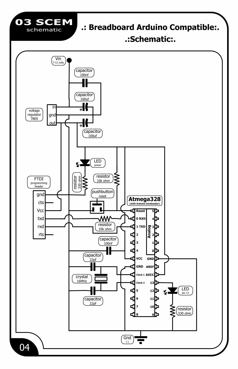
03 SCEMschematic .: Breadboard Arduino Compatible:.
.:Schematic:.
resistor330 ohm
LEDpin 13
Gnd(-)
pushbuttonreset
capacitor100nf
resistor10k ohm
crystal16MHz
capacitor22pf
capacitor22pf
Vcc
txd
rxd
rts
cts
resi
stor
330 o
hm
gnd
resistor10k ohmFTDI
programmingheader
LEDpower
capacitor100uf
voltage regulator
7805
in
gnd
out
++
capacitor100uf
capacitor100nf
Vin7-12 volts
Reset 5
0 RXD 4
1 TXD 3
2 2
3 1
4 0
VCC GND
GND AREF
Clock 1 AVCC
Clock 2 13
5 12
6 11
7 10
8 9
An
alo
g
Atmega328(with Arduino bootloader)
05
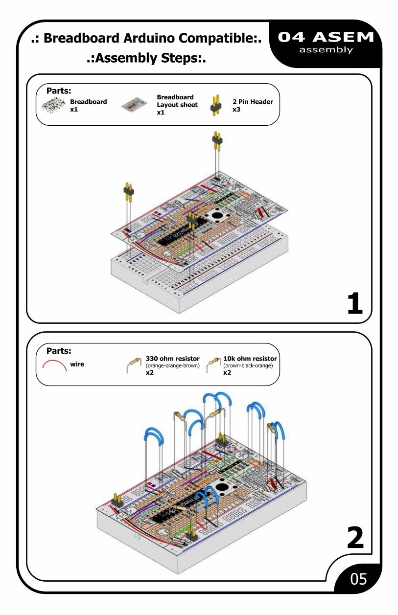
04 ASEMassembly
1
2
2 Pin Headerx3
Parts:Breadboard Layout sheetx1
Breadboardx1
Parts:
wire330 ohm resistor(orange-orange-brown)
x2
10k ohm resistor(brown-black-orange)
x2
.: Breadboard Arduino Compatible:.
.:Assembly Steps:.

06
04 ASEMassembly
3
4
Parts:Capacitor100 nf (104)x2
Parts:
Pushbuttonx1
Capacitor100 ufx2
Capacitor22 pf (220)x2
Header (6 pin)x1
Red LEDx1
Green LEDx1
The 100 uf capacitors are polarized.Put the longer lead in the indicated hole
the decoupling capacitors will have 104 written on them
the smoothing capacitors will have 220 written on them

07
04 ASEMassembly
5
6
Voltage Regulator(7805)x1
Parts:Crystal(16 MHz)x1
MicrocontrollerATMega328x1
Parts:
Wire Battery Clipx1
There is a half moon cutout, this goes at the top
08
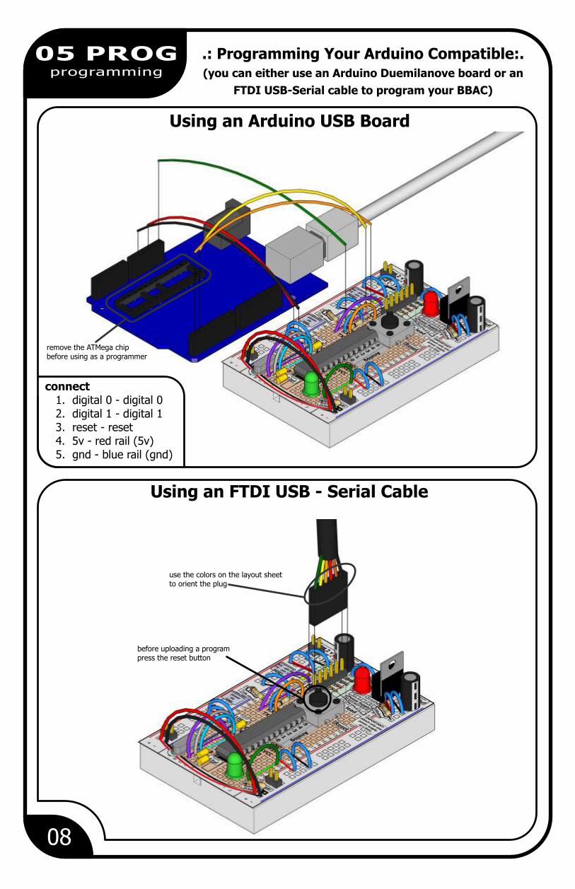
05 PROGprogramming
Using an Arduino USB Board
Using an FTDI USB - Serial Cable
remove the ATMega chipbefore using as a programmer
connect 1. digital 0 - digital 0 2. digital 1 - digital 1 3. reset - reset 4. 5v - red rail (5v) 5. gnd - blue rail (gnd)
before uploading a program press the reset button
use the colors on the layout sheetto orient the plug
.: Programming Your Arduino Compatible:.(you can either use an Arduino Duemilanove board or an
FTDI USB-Serial cable to program your BBAC)
09
06 NOTEnotes
.: Notes:.
.:Room for a Few Notes:.

This work is licenced under the Creative Commons Attribution-Share Alike 3.0 Unported License. To view a copy of this licence, visit http://creativecommons.org/licenses/by-sa/3.0/ or send a letter to Creative Commons, 171 Second Street, Suite 300, San Francisco, California 94105, USA.
(BBAC)breadboard arduino
compatible
www.oomlout.com


