Compensating algorithm suitable for use with measurement-type current transformers for protection Y.C. Kang, U.J. Lim and S.H. Kang Abstract: Requirements to avoid current-transformer (CT) saturation result in impractically large CTs. The paper describes the design, evaluation and implementation of a compensating algorithm for the distorted secondary current of the CT caused by saturation. The algorithm can compensate the distorted current irrespective of the level of the remanent flux and is suitable for use with measurement-type CTs for protection. A second-difference function detects when a CT first starts to saturate. At the start of first saturation, the negative value of the second-difference function corresponds to the magnetising current; which is used in conjunction with the magnetisation curve to obtain the core flux. This value is then used as an initial flux to calculate the core flux. The magnetising current is determined by inserting the calculated core flux into the magnetisation curve and added to the secondary current. The resultant compensated current is equal to the secondary referred primary current. Test results indicate that the algorithm can compensate accurately the severely distorted currents caused by the small size of measurement CTs and is not affected by the remanent flux. The paper concludes by describing the experimental test results on a small CT using a prototype compensation system based on a digital signal processor. 1 Introduction The output current from a current transformer (CT) distorts when the core saturates. This is particularly onerous when the remanent flux in the core of the CT adds to the flux change caused by the fault. The CT is forced into deep saturation and the secondary current is severely distorted. CT saturation may result in the delay or maloperation of a protection relay. To minimise the problem, protection relays are designed to operate with CTs large enough to prevent saturation or to use operating algorithms which are insensitive to the effects of saturation. Many studies on the analysis of the steady-state and transient behaviour of CTs have been reported [1–3] . The DC component of an asymmetrical fault current greatly increases the flux in a CT. When the DC offset is at a maximum, the flux can potentially reach 1+X/R times the flux resulting from the sinusoidal component, where X and R are the primary system reactance and resistance up to the point of the fault. To avoid saturation with a DC component, IEEE standard C37.1101996 specifies: ‘the required saturation voltage should exceed I s * Z s * (1+X/R), where I s and Z s are the primary current divided by the turns ratio and the total secondary burden, respectively’ [4] . Moreover, if remanence is considered, the required satura- tion voltage is increased several times, more depending on the amount of remanence. These requirements generally result in impractically large CTs, but cost and practical limitations mean that saturation cannot be avoided. There- fore, compensating methods can be used to minimise the saturation effects on the relay protection plan or to reduce the requirements to avoid saturation. Digital compensating algorithms have been reported and can be classified roughly into two groups: the analytical method [5–8] and the ANN-based method [9]. The analytical method can then be divided into two groups: the CT-model-based method [5–7] and the regression- technique-based method [8]. The former requires some parameters of the CT while the latter does not. Kang et al. proposed an algorithm for compensating the secondary current of a CT [5]. The flux was calculated and used to estimate the magnetising current in conjunction with the magnetisation curve. This was then added to the measured secondary current to create an estimate of the ‘correct’ secondary current, i.e. the secondary-referred primary current. The technique is valid, but relies on the assumption that the remanent flux is zero before the fault. Locci and Muscas suggested digital-compensation meth- ods to improve the accuracy of a measurement CT [6, 7] . The initial core flux was estimated and used in conjunction with the hysteresis curve to calculate the exciting current. However, the technique is valid only for slight saturation and relies on the assumption that there is no remanent flux in the core. Li et al. reported a digital method that combines the wavelet transform and the regression technique to compen- sate the distorted secondary current of CTs [8] . It first uses the wavelet transform to distinguish the distorted section of a current waveform from the healthy section. Secondly, it uses the regression technique to compensate the distorted section utilising the features extracted from the healthy Y.C. Kang and U.J. Lim are with the NPTC and Division of Electronics and Information Engineering, Chonbuk National University, Chonju 561-756, Korea S.H. Kang is with the NPTC and Department of Electrical Engineering, Myongji University, Yongin 449-728, Korea E-mail: [email protected]r IEE, 2005 IEE Proceedings online no. 20045115 doi:10.1049/ip-gtd:20045115 Paper first received 22nd July 2004 and in final revised form 14th April 2005 880 IEE Proc.-Gener. Transm. Distrib., Vol. 152, No. 6, November 2005
Transcript
Compensating algorithm suitable for use withmeasurement-type current transformers forprotection
Y.C. Kang, U.J. Lim and S.H. Kang
Abstract: Requirements to avoid current-transformer (CT) saturation result in impractically largeCTs. The paper describes the design, evaluation and implementation of a compensating algorithmfor the distorted secondary current of the CT caused by saturation. The algorithm can compensatethe distorted current irrespective of the level of the remanent flux and is suitable for use withmeasurement-type CTs for protection. A second-difference function detects when a CT first startsto saturate. At the start of first saturation, the negative value of the second-difference functioncorresponds to the magnetising current; which is used in conjunction with the magnetisation curveto obtain the core flux. This value is then used as an initial flux to calculate the core flux. Themagnetising current is determined by inserting the calculated core flux into the magnetisation curveand added to the secondary current. The resultant compensated current is equal to the secondaryreferred primary current. Test results indicate that the algorithm can compensate accurately theseverely distorted currents caused by the small size of measurement CTs and is not affected by theremanent flux. The paper concludes by describing the experimental test results on a small CT usinga prototype compensation system based on a digital signal processor.
1 Introduction
The output current from a current transformer (CT)distorts when the core saturates. This is particularly onerouswhen the remanent flux in the core of the CT adds to theflux change caused by the fault. The CT is forced into deepsaturation and the secondary current is severely distorted.CT saturation may result in the delay or maloperation of aprotection relay. To minimise the problem, protection relaysare designed to operate with CTs large enough to preventsaturation or to use operating algorithms which areinsensitive to the effects of saturation.
Many studies on the analysis of the steady-state andtransient behaviour of CTs have been reported [1–3]. TheDC component of an asymmetrical fault current greatlyincreases the flux in a CT. When the DC offset is at amaximum, the flux can potentially reach 1+X/R times theflux resulting from the sinusoidal component, where X andR are the primary system reactance and resistance up to thepoint of the fault. To avoid saturation with a DCcomponent, IEEE standard C37.110�1996 specifies: ‘therequired saturation voltage should exceed Is
*Zs*(1+X/R),
where Is and Zs are the primary current divided by the turnsratio and the total secondary burden, respectively’ [4].Moreover, if remanence is considered, the required satura-
tion voltage is increased several times, more depending onthe amount of remanence. These requirements generallyresult in impractically large CTs, but cost and practicallimitations mean that saturation cannot be avoided. There-fore, compensating methods can be used to minimise thesaturation effects on the relay protection plan or to reducethe requirements to avoid saturation.
Digital compensating algorithms have been reported andcan be classified roughly into two groups: the analyticalmethod [5–8] and the ANN-based method [9]. Theanalytical method can then be divided into two groups:the CT-model-based method [5–7] and the regression-technique-based method [8]. The former requires someparameters of the CT while the latter does not.
Kang et al. proposed an algorithm for compensating thesecondary current of a CT [5]. The flux was calculated andused to estimate the magnetising current in conjunctionwith the magnetisation curve. This was then added to themeasured secondary current to create an estimate of the‘correct’ secondary current, i.e. the secondary-referredprimary current. The technique is valid, but relies on theassumption that the remanent flux is zero before the fault.
Locci and Muscas suggested digital-compensation meth-ods to improve the accuracy of a measurement CT [6, 7].The initial core flux was estimated and used in conjunctionwith the hysteresis curve to calculate the exciting current.However, the technique is valid only for slight saturationand relies on the assumption that there is no remanent fluxin the core.
Li et al. reported a digital method that combines thewavelet transform and the regression technique to compen-sate the distorted secondary current of CTs [8]. It first usesthe wavelet transform to distinguish the distorted section ofa current waveform from the healthy section. Secondly, ituses the regression technique to compensate the distortedsection utilising the features extracted from the healthy
Y.C. Kang and U.J. Lim are with the NPTC and Division of Electronics andInformation Engineering, Chonbuk National University, Chonju 561-756,Korea
S.H. Kang is with the NPTC and Department of Electrical Engineering,Myongji University, Yongin 449-728, Korea
section. It can compensate the distorted secondary currentin the presence of remanence in the core. However,difficulty arises if there is a small number of samples inthe healthy section because of early saturation. It requires10ms for compensating a complete cycle, involvingsaturation detection using wavelet transform and compen-sation with regression technique. In addition, a largecomputational burden is also inevitable when using theregression technique.
Yu et al. suggested an ANN-based approach forcorrecting the distorted secondary current of a CT [9].The ANNwas trained to provide the inverse function of theCT. However, only the DC component was considered ofthe three factors that affect CT saturation, i.e. the DCcomponent, the primary time constant and the remanentflux in the core.
To date, there is no proper compensating algorithmavailable that can cope fully with the remanent flux.Recently, Kang et al. suggested a CT saturation-detectionalgorithm based on the difference function of the current[10]. The start and end of each saturation period aredetected based on the third-difference function, irrespectiveof the level of the remanent flux. In addition, at thesaturation start, the negative value of the second-differencefunction, could be approximated as the magnetisingcurrent.
This paper describes the design, evaluation, and im-plementation of a compensating algorithm for the distortedsecondary current of a CT caused by saturation in real time.To cope with the remanent flux, the algorithm combines acompensating algorithm in [5] in conjunction with detectionof the first saturation start based on a technique in [10]. Itcompensates the severely distorted current irrespective ofthe level of remanent flux, even when a measurement CT isused and gets more severely saturated because of its smallsize. A second-difference function detects the start of firstsaturation, where the negative value of the second differencecan be approximated as the magnetising current at thisinstant. Thus, the flux at this instant is obtained by puttingthe negative value of the second-difference into themagnetisation curve. Thereafter, at every sampling interval,the core flux is calculated and used to estimate themagnetising current. The ‘correct’ secondary current isestimated by adding the estimated magnetising current tothe measured secondary current. The operating perfor-mance of the algorithm was tested under various faultand CT conditions including variations in the fault-inception angle, the remanent flux, the primary timeconstant and the type of fault. The effect of autoreclosurewas also investigated. Two types of CT were used in thestudies: the C400 rated protection CT and the C40measurement CT. The algorithm was implemented on aprototype compensation system based on a digital signalprocessor. The system was tested experimentally in thelaboratory using signals from a small CT with a turns ratioof 300:5.
2 Compensating algorithm irrespective of thelevel of the remanent flux
2.1 Compensating algorithm [5]The operating principle of the compensating algorithm usedin [5] is briefly described. Figure 1 shows a simplifiedequivalent circuit of a CT, where Lm is the magnetisationinductance, R is the total secondary resistance, i1(t) is theprimary current referred to the secondary, im(t) isthe magnetising current and i2(t) is the secondary current.
The relationship between i1(t), im(t) and i2(t) is
i1ðtÞ ¼ imðtÞ þ i2ðtÞ ð1Þ
The relay measures i2(t); consequently if im(t) can bedetermined, the ‘correct’ secondary current i1(t) can beestimated.
The core flux l(t) is related to i2(t) by the expression
dlðtÞdt¼ Ri2ðtÞ ð2Þ
Integrating (2) from t0 to t yields
lðtÞ � lðt0Þ ¼ RZ t0
ti2ðtÞdt ð3Þ
If the initial flux l(t0) is known, l(t) can be calculated using(3). Its value at every sample is then applied to the CT-magnetisation curve to obtain the magnetising current. Thisis then added to the measured secondary current and theresult is an estimate of the correct secondary current.However, in [5], l(t0) could be obtained only if no remanentflux existed in the core. Therefore, if a remanent flux exists,the compensated current may contain significant errors.
2.2 Compensating algorithm immune tothe remanent fluxTo cope with the drawback of the algorithm in [5], thispaper describes an advanced compensating algorithm forthe distorted secondary current immune to the remanentflux. To do this, it estimates l(t0) not ‘before saturation’ but‘after saturation’. It first detects the start of first saturationand obtains the flux at the saturation start, which is used asl(t0). It then evaluates l(t) and uses it to estimate thesecondary current that would have been seen if the CT hadnot saturated.
2.2.1 Detection of the start of first saturation[10]: The operating principle of detecting the start andend of each saturation period was explained in [10]. Thispaper utilises the technique for detecting only the start offirst saturation. The operating principle is described here
For to0, i1(t) is 0 and for tZ0, i1(t) is given by
i1ðtÞ ¼ Imaxfcosðot � yÞ � expð�t=TpÞg ð4Þ
where Imax, Tp, and y are the maximum fault current, theprimary time constant and the fault-inception angle,respectively.
i2(t) can be expressed as
i2ðtÞ ¼ A expð�t=TsÞ þ B expð�t=TpÞ� C sinðot � y� fÞ ð5Þ
where Ts is the secondary time constant and tan f¼oTs [3].
R
i1 i2
im
Lm
Fig. 1 Simplified equivalent circuit of a current transformer
ð7ÞIf the power frequency is 60Hz and N¼ 64, T¼ 0.26ms. IfTs¼ 1 s and Tp¼ 0.02 s, the reduction rates for theexponential terms [(1�eT/Ts) and (1�eT/Tp)] are 0.00026and 0.0131; i.e. the exponential terms in del 1[n] are reducedto a negligible value.
On the other hand, the magnitude of the sinusoid indel 1[n] is reduced to 2sin(p/N)C¼ 0.098C, i.e. a decrease of90%. Consequently, if i2[n] has the form of (6) and the timeconstants are sufficiently large, then the only component indel 1[n] is a sinusoid and its magnitude is 0.098C.
The second difference function of i2[n] is defined as:
del 2½n� ¼ del 1½n� � del 1½n� 1� ð8Þwhere del 2[n] is also a sinusoid with the magnitude of{2sin(p/N)}2C ¼ 0.009604C. Hence, the magnitude of thesinusoid in del 2[n] is reduced to 1% of its value in i2[n].
Let us assume that saturation starts at n¼m+1 andi21[n] and i22[n] are the secondary currents before and duringsaturation (see Fig. 2a). The two signals are continuouswithin their monitoring period. Hence, i21[m]¼ i22[m] buti21[m+1]ai22[m+1]; note that i21[m+1] is not an actualsample but a virtual sample on the extended line of i21[n].The function del 2[n] in the interval before the start ofsaturation, i.e. nrm, is a sinusoid and its magnitude doesnot exceed {2sin(p/N)}2C. For example, if C¼ 100 A andN¼ 64, then {2sin(p/N)}2C¼ 0.96 A and the sinusoid indel 2[n] is equal to or less than 0.96 A.
The value of del 2[m+1] in (9) is obtained with themeasured currents. The approximation of (10) can be madewith a maximum error of 0.96 A:
i21½mþ 1� � 2i21½m� þ i21½m� 1� ’ 0 ð10ÞHence, del 2[m+1] can be approximated as i22[m+1]�i21[m+1], i.e. �del 2[m+1]C i21[m+1]�i22[m+1]. Notethat i21[m+1] is the value at n¼m+1 on the extendedline if the CT had not saturated. Thus, �del 2[m+1] can beregarded as the magnetising current at n¼m+1. Thisbecause the magnetising current at n¼m+1 is thedifference between i21[m+1] and i22[m+1] (see Fig. 2a).Its value is significantly greater than 0.96 A, but depends onthe core flux at n¼m+1. During the saturated period,m+2rnrk, the magnitude of del 2[n], which is also asinusoid, is smaller than before saturation. Consequently,the magnitude of del 2[n], which is a sinusoid, is smaller than0.96 A except for the saturation start. The value of del 2[n]at the saturation start is significantly greater than 0.96 A.
The instant that satisfies (11) can be determined as thestart of first saturation:
del 2½n�j j � Th ð11Þwhere the threshold Th is decided by:
Th ¼ k 2p
If maxf2 sinðp=NÞg2 ð12Þand Ifmax is the expected maximum fault current and k is amargin factor that considers the operating sensitivity of thedetector and the smoothing behaviour of the lowpass filter.
2.2.2 Determination of the initial core fluxl(t0): The magnetisation curve relates l(t) to im(t). Thus,the core flux at the start of first saturation can be estimatedby referring�del 2[m+1], which is calculated in accordancewith (9), to the magnetisation curve (see Fig. 2b) and usedas the initial flux l(t0). Note that the level of the remanent
m m+1
i21[n]
i22[n]
−del2[m +1]
−del2[m +1]
a
b
im , A
�(Vs)
�(t0)
c
im , A
im (t )
�(Vs)
�(t )
Fig. 2 Distorted secondary current and determination of l(t0) andIm(t)a Secondary current and its second differenceb Determination of l(t0)c Estimation of Im(t)
flux in the core can influence the start, degree and durationof saturation, but not the flux at the start of saturation.Thus, l(t0) estimated by the proposed algorithm does notrely on the level of the remanent flux.
2.2.3 Estimation of the correct secondarycurrent: Once l(t0) is derived, it is used by (3) tocalculate l(t) during the period of the fault. l(t) is thenapplied to the magnetisation curve and the magnetisingcurrent obtained (see Fig. 2c). The primary current referredto the secondary, i.e. the ‘correct’ secondary current, is thenestimated by summing the measured secondary current andthe estimated magnetising current.
The proposed algorithm can compensate the severelydistorted current of the saturated CT at every sample,irrespective of the level of remanent flux. Thus, it cancompensate the current even though a measurement CT isused and gets saturated more severely because of its size.Therefore, the algorithm can reduce significantly therequired core cross-section of the CT to avoid saturation.The flowchart of the algorithm is shown in Fig. 3.
3 Case studies
Figure 4 shows a single-line diagram of a typical Korean345kV transmission system. The simulated fault involves‘A’ phase-to-ground and is located 2km from the P bus.The sampling rate is 64 samples per cycle (3840Hz at 60Hz) and all the currents are passed through first order
lowpass RC filters with cutoff frequencies of 1920Hz, i.e.half the sampling frequency.
For the case studies, two kinds of CTs were chosen:C400¼ 2000:5 rated protection CTs (used on Korean 345kV transmission lines) and C40¼ 2000:5 measurement CTs.The CT modelling method described in [11] is used tosimulate the remanent flux. Both CTs are connected to aresistive load of 3.42O. The saturation point of the CT wasselected as 2.05 A at 1.51Vs for C400 and 2.05A at0.151Vs for C40. This is then used to generate hysteresisdata using HYSDAT, an auxiliary program in EMTP.Figure 5 shows the magnetisation curves of the C400 CT(solid line) and C40 CT (dotted line) used to estimate themagnetising current.
The secondary current also contains a point of inflectionat the inception of the fault. This results in a peak in del 2[n]that may be detected as the start of first saturation. Toprevent maloperation, the detection algorithm is onlyactivated if the current exceeds twice the rated secondarycurrent for two successive samples. The threshold used todetect saturation is set to 1.9 A, which corresponds to k¼ 2.
To verify the performance of the algorithm, the transienterror [12] for the compensated current is calculated at everysampling instant:
transient errorð%Þ ¼ Kni2ðtÞ � i1ðtÞ2p
Ipsc� 100ð%Þ ð13Þ
where Ipsc is the rated primary short-circuit current and Kn isthe turns ratio of a CT.
The performance of the algorithm was tested for a varietyof scenarios chosen to investigate the effect of the fault-inception angle, the remanent flux and the primary timeconstant t, different types of fault and autoreclosure. In all
|del2| > Th
yes
no
yes
nosat_ind = 1
calculation of flux
calculation ofinitial flux
sat_ind = 1
calculation of del2
calculation ofmagnetising current
compensation
protection relay
sat_ind = 0
currents
start
Fig. 3 Flowchart of the proposed algorithm
CT
30 (GVA) 7 (GVA)
2 (km) 98 (km)
Zs
P Q
Fig. 4 Simulated power-system model
0 0.5 1.51.0 2.52.0 3.00
0.2
0.4
0.6
0.8
1.0
1.2
1.4
1.6
flux,
Vs
im, A
Fig. 5 Magnetisation curves of the C400 and C40 currenttransformers——— C400– – – – C40
the Figures in Section 3, the solid and dotted lines are theresults for C400 and C40, respectively.
3.1 Fault-inception angleThe DC component has far more influence on saturationthan the magnitude of the AC fault current. The resultswith a fault-inception angle of 01 are shown.
Case 1: 01 fault, t¼ 20 ms, 0% remanent fluxFigure 6 shows the results for case 1. The fault occurs at33ms. In Fig. 6a, the thick solid line is the ‘correct’secondary current, which corresponds to the primary
current divided by the turns ratio; the thin solid anddotted lines are the measured secondary currents forC400 and C40, respectively. A fault-inception angle of0 results in a large DC component, which saturates theCTs and distorts the secondary current. As expected,the current for C40 is much more severely distorted thanthat for C400 because of its small size. The start ofsaturation is detected at 39.3ms for C400 and at 35.9ms forC40. The initial core fluxes of 1.53Vs (C400) and 0.154Vs(C40) are obtained by inserting the negative values of thesecond difference into the magnetisation curves of Fig. 5.The core fluxes calculated after saturation exceed thesaturation levels as shown in Fig. 6b. Figure 6c shows themagnetising currents estimated by inserting the calculatedcore fluxes into the magnetisation curves. The compensatedsecondary currents are obtained by adding the estimatedmagnetising currents of Fig. 6c to the measured secondarycurrents of Fig. 6a. Figure 6d shows the correct andcompensated secondary currents for C400 and C40, andthey appear to be nearly identical. Figure 6e shows thetransient errors of (13) for the compensated currents ofC400 and C40. They are less than 1.2% (C400) and 0.6(C40). The results show that the algorithm can accuratelyestimate the correct secondary current even with ameasurement CT.
3.2 Remanent fluxRemanent flux affects the degree and duration of satura-tion. The algorithm was tested at remanent-flux levelsvarying from –80% to +80% of the flux value at the kneepoint. The test results for the two of the fault scenarios aredescribed in cases 2 and 3.
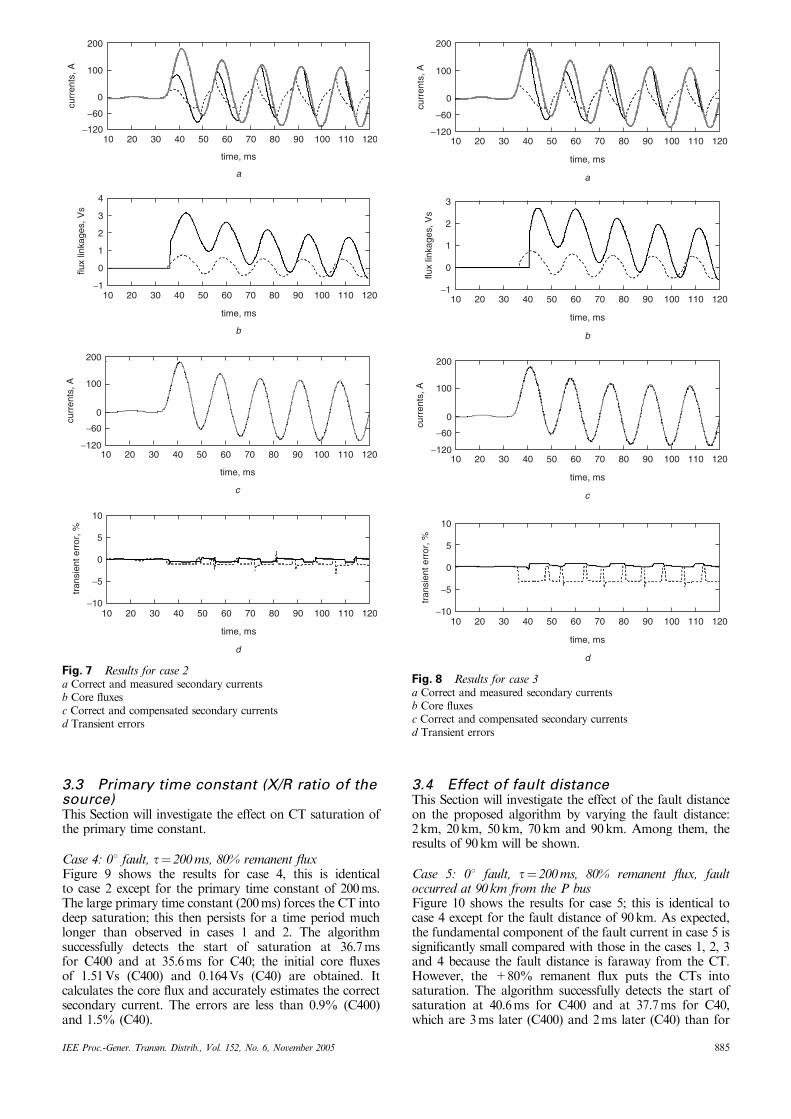
Case 2: 01 fault, t¼ 20 ms, +80% remanent fluxCase 2 is the same as case 1 except that the remanent-fluxlevel is +80%. The results are shown in Fig. 7. The positiveremanent flux forces the CT into saturation earlier (36.7msfor C400 and 35.6ms for C40) and the level of saturation ismore severe than in case 1. The algorithm detects the startof saturation and initial core fluxes of 1.51Vs (C400) and0.164Vs (C40) are obtained; then it calculates the core fluxand estimates the correct secondary current. The errors arevery small, i.e. less than 0.34% for C400 and 1.3% for C40,as shown in Fig. 7d.Case 3: 01 fault, t¼ 20 ms, �80% remanent fluxFigure 8 shows the results for case 3; this is identical to cases1 and 2 except that the remanent-flux level is at �80%. Thenegative remanent-flux slows the onset of saturation(41.1ms for C400 and 36.7ms for C40) and the level ofsaturation is less severe than in cases 1 and 2. The algorithmdetects the start of saturation and the initial core fluxes of1.58Vs (C400) and 0.186Vs (C40) are obtained. It estimatesthe correct secondary currents; the errors are less than0.75% for C400 and 3.6% for C40.
In this case, the error of C40 is larger than the othercases. This is because the algorithm detects the saturationstart one sample later. This results from asynchronism atthe start of saturation, i.e. at the point of inflection that canbe observed when comparing the sampled current i2[n] andthe original current i2(t), which was explained in detail inSection 3.1 in [10]. Consequently, it causes errors in thecompensated current. However, the error is small (less than3.6%) even if saturation detection is delayed by one sample.
The results clearly demonstrate that the algorithm cancompensate the distorted secondary current irrespective ofthe level of the remanent flux even when a measurement CTis used.
200
100
0
−120
−60
curr
ents
, A
2010 4030 6050 80 90 100 110 12070
time, ms
a
200
100
0
−120
−60
curr
ents
, A
2010 4030 6050 80 90 100 110 12070
time, ms
d
3
2
1
−1
0
flux
linka
ges,
Vs
2010 4030 6050 80 90 100 110 12070
time, ms
b
200
100
0
−100
mag
netis
ing
curr
ents
, A
2010 4030 6050 80 90 100 110 12070
time, ms
c
10
5
−5
0
−10
tran
sien
t err
or, %
2010 4030 6050 80 90 100 110 12070
time, ms
e
Fig. 6 Results for case 1a Correct and measured secondary currentsb Core fluxesc Estimated magnetising currentsd Correct and compensated secondary currentse Transient errors
3.3 Primary time constant (X/R ratio of thesource)This Section will investigate the effect on CT saturation ofthe primary time constant.
Case 4: 01 fault, t¼ 200 ms, 80% remanent fluxFigure 9 shows the results for case 4, this is identicalto case 2 except for the primary time constant of 200ms.The large primary time constant (200ms) forces the CT intodeep saturation; this then persists for a time period muchlonger than observed in cases 1 and 2. The algorithmsuccessfully detects the start of saturation at 36.7msfor C400 and at 35.6ms for C40; the initial core fluxesof 1.51Vs (C400) and 0.164Vs (C40) are obtained. Itcalculates the core flux and accurately estimates the correctsecondary current. The errors are less than 0.9% (C400)and 1.5% (C40).
3.4 Effect of fault distanceThis Section will investigate the effect of the fault distanceon the proposed algorithm by varying the fault distance:2km, 20km, 50km, 70km and 90km. Among them, theresults of 90km will be shown.
Case 5: 01 fault, t¼ 200 ms, 80% remanent flux, faultoccurred at 90 km from the P busFigure 10 shows the results for case 5; this is identical tocase 4 except for the fault distance of 90km. As expected,the fundamental component of the fault current in case 5 issignificantly small compared with those in the cases 1, 2, 3and 4 because the fault distance is faraway from the CT.However, the +80% remanent flux puts the CTs intosaturation. The algorithm successfully detects the start ofsaturation at 40.6ms for C400 and at 37.7ms for C40,which are 3ms later (C400) and 2ms later (C40) than for
200
100
0
−120
−60
curr
ents
, A
2010 4030 6050 80 90 100 110 12070
time, ms
c
3
4
2
1
−1
0flux
linka
ges,
Vs
2010 4030 6050 80 90 100 110 12070
time, ms
b
10
5
−5
0
−10
tran
sien
t err
or, %
2010 4030 6050 80 90 100 110 12070
time, ms
d
0
200
100
−120
−60
curr
ents
, A
2010 4030 6050 80 90 100 110 12070
time, ms
a
Fig. 7 Results for case 2a Correct and measured secondary currentsb Core fluxesc Correct and compensated secondary currentsd Transient errors
200
100
0
−120
−60
curr
ents
, A
2010 4030 6050 80 90 100 110 12070
time, ms
a
2010 4030 6050 80 90 100 110 12070
time, ms
c
200
100
0
−120
−60
curr
ents
, A
2010 4030 6050 80 90 100 110 12070
time, ms
b
3
2
1
−1
0
flux
linka
ges,
Vs
2010 4030 6050 80 90 100 110 12070
time, ms
d
10
5
−5
0
−10
tran
sien
t err
or, %
Fig. 8 Results for case 3a Correct and measured secondary currentsb Core fluxesc Correct and compensated secondary currentsd Transient errors
case 4. The initial core fluxes of 1.51Vs (C400) and 0.152Vs(C40) are obtained. It calculates the core flux and accuratelyestimates the correct secondary current. The errors are lessthan 2.6% (C400) and 2.0% (C40).
3.5 Effect of different types of faultThe proposed algorithm does not depend on the type offault. This Section will show the results of an A-phase-to-B-phase fault at 2km from the P bus, where the remanentflux is +80% in the CTs of both phases.
Case 6: A-phase-to-B-phase fault, 01 fault (A phase),t¼ 200 ms, +80% remanent fluxFigure 11 shows the results for case 6. Figure 11a and bshows the currents of the ‘A’ and ‘B’ phases. The +80%remanent flux forces the CTs of the ‘A’ phase intosaturation earlier whilst the +80% remanent flux slows
the start of saturation in the CTs of the ‘B’ phase. This isbecause the remanent flux in the CTs of the ‘B’ phase is inthe opposite direction to the flux change. As previous cases,for the ‘A’ phase, the algorithm detects the start ofsaturation at 35.6ms for C400 and 34.8ms for C40 andcompensates the distorted secondary currents. The errorsfor the ‘A’ phase are less than 0.8% (C400) and 1.9% (C40);the errors for the ‘B’ phase are less than 1.1% (C400) and0.5% (C40).
3.6 AutoreclosureA large remanent flux may exist in a CT after the clearanceof a fault. If an autoreclosure scheme then re-energises thefault, the CT may enter deep saturation and the secondarycurrent will be severely distorted after reclosure. Toinvestigate the effect of autoreclosure on the performanceof the algorithm, two reclosure sequences were studied.
0
220
110
−100
curr
ents
, A
2010 4030 6050 80 90 100 110 12070
time, ms
a
4
3
2
1
−1
0flux
linka
ges,
Vs
2010 4030 6050 80 90 100 110 12070
time, ms
b
220
110
0
−100
curr
ents
, A
2010 4030 6050 80 90 100 110 12070
time, ms
c
10
5
−5
0
−10
tran
sien
t err
or, %
2010 4030 6050 80 90 100 110 12070
time, ms
d
Fig. 9 Results for case 4a Correct and measured secondary currentsb Core fluxesc Correct and compensated secondary currentsd Transient errors
0
30
20
10
−20
−10
curr
ents
, A
2010 4030 6050 80 90 100 110 12070
time, ms
a
2010 4030 6050 80 90 100 110 12070
time, ms
c
30
20
0
−20
−10
10
curr
ents
, A
2010 4030 6050 80 90 100 110 12070
time, ms
b
1.5
2.0
1.0
0.5
−0.5
0
flux
linka
ges,
Vs
2010 4030 6050 80 90 100 110 12070
time, ms
d
10
5
−5
0
−10
tran
sien
t err
or, %
Fig. 10 Results for case 5a Correct and measured secondary currentsb Core fluxesc Correct and compensated secondary currentsd Transient errors
Case 7: 901 fault at 20.8 ms, t¼ 200 ms, 80% remanent flux,opens at 45.7 ms and recloses at 87.5 msFigure 12 shows the results for case 7. The initial 901 faultoccurs at 20.8ms and the fault current has no DCcomponent. However, +80% remanent flux results insevere distortion of the currents prior to fault clearance. Thealgorithm detects the start of saturation at 22.9ms (C400)and 21.8ms (C40) and the initial core fluxes of 1.54Vs(C400) and 0.167Vs (C40) are obtained. After clearance, theremanent flux exists in the core and decays. The values of1.42Vs (C400) and 0.122Vs (C40) at the instant of reclosureresults in severe saturation of the CTs after reclosure as well.Figures 12c and 11d demonstrates that the algorithm
successfully compensates the severely distorted current dueto its small size and the errors are less than 1.3% (C400) and3.3% (C40). The reason why the error of C40 is large is thesame as in case 3.Case 8: 01 fault at 16.7 ms, t¼ 200 ms, 80% remanent flux,open at 47.0 ms and recloses at 85 msFigure 13 shows the results for case 8. The 01 fault occurs at16.7ms. Before clearance, the core fluxes are so large thatthe currents are severely distorted. The algorithm detects thestart of saturation at 20.0ms (C400) and at 18.9ms (C40)and the initial core fluxes of 1.52Vs (C400) and 0.164Vs(C40) are obtained. After clearance, the remanent flux existsin the core and decays. The values of 1.43Vs (C400) and
250
125
0
−120
curr
ents
, A
2010 4030 6050 80 90 100 110 12070
time, ms
a
2010 4030 6050 80 90 100 110 12070
time, ms
b
120
0
−125
−250
curr
ents
, A
2010 4030 6050 80 90 100 110 12070
time, ms
c
3
2
4
1
−1
0flux
linka
ges,
Vs
2010 4030 6050 80 90 100 110 12070
time, ms
d
−4
−3
−1
−2
1
0
flux
linka
ges,
Vs
2010 4030 6050 80 90 100 110 12070
time, ms
e
250
125
0
−120
curr
ents
, A
2010 4030 6050 80 90 100 110 12070
time, ms
f
120
0
−125
−250
curr
ents
, A
2010 4030 6050 80 90 100 110 12070
time, ms
g
10
5
−5
0
−10
tran
sien
t err
or, %
2010 4030 6050 80 90 100 110 12070
time, ms
h
10
5
−5
0
−10
tran
sien
t err
or, %
Fig. 11 Results for case 6a Correct and measured secondary currents (A phase)b Correct and measured secondary currents (B phase)c Core fluxes (A phase)d Core fluxes (B phase)e Correct and compensated secondary currents (A phase)f Correct and compensated secondary currents (B phase)g Transient errors (A phase)h Transient errors (B phase)
0.126Vs (C40) at the instant of reclosure result in severesaturation of the CTs after reclosure as well. However, thealgorithm successfully compensates the severely distortedsecondary current. The errors are less than 1.0% (C400)and 2.5% (C40).
Moreover, in cases 7 and 8, when the fault is clearedand the primary current is zero, a unidirectional transientcurrent (depending on the core flux at the instant of thefault clearance) flows in the secondary; this may delaythe reset of the sensitive high-speed overcurrent relaysused in breaker-failure protective schemes. However, thealgorithm can also compensate the unidirectional transientcurrent.
4 Experimental test results
This Section describes a series of experimental tests ofthe algorithm on a small CT in the laboratory. Figure 14
shows the configuration of the test system and themagnetisation curve of the CT used. The turns ratioof the CT is 300:5 and a large load ensures deep saturation.A ‘DC CT’ is used to measure the primary current.To obtain the magnetisation curve, when a fault occursand the CT is saturated so deeply, the core flux is calculatedby integrating the secondary voltage of the CT andthe magnetising current was obtained from the differencebetween the primary and secondary currents. Then thehysteresis curve was obtained from the core flux andthe magnetising current. Finally, the magnetisation curveof Fig. 13 was obtained from the hysteresis curve. Thealgorithm is implemented on the TMS320C6701 digitalsignal processor. The sampling rate is 64 samples/cycleand the currents are passed through 1st order RC filters(fc¼ 1920 Hz), to the 14-bit A/D convertor. The thresholdfor saturation detection is set to 1.0A correspondingto k¼ 3.
120
0
−120
curr
ents
, A
2010 4030 6050 80 90 100 110 12070
time, ms
a
2010 4030 6050 80 90 100 110 12070
time, ms
b
3
2
1
−1
−2
0
flux
linka
ges,
Vs
2010 4030 6050 80 90 100 110 12070
time, ms
c
120
0
−120
curr
ents
, A
2010 4030 6050 80 90 100 110 12070
time, ms
d
10
5
−5
0
−10
tran
sien
t err
or, %
Fig. 12 Results for case 7a Correct and measured secondary currentsb Core fluxesc Correct and compensated secondary currentsd Transient errors
10 20 30 40 50 60 70 80 90 100 110 120
time, ms
−100
0
110
220
curr
ents
, A
a
flux
linka
ges,
Vs
−1
0
1
2
3
4
10 20 30 40 50 60 70 80 90 100 110 120
time, ms
b
−100
0
110
220
curr
ents
, A
10 20 30 40 50 60 70 80 90 100 110 120
time, ms
c
−10
−5
0
5
10
tran
sien
t err
or, %
10 20 30 40 50 60 70 80 90 100 110 120
time, ms
d
Fig. 13 Results for case 8a Correct and measured secondary currentsb Core fluxesc Correct and compensated secondary currentsd Transient errors
Figures 15 and 16 show two sets of experimental results.Figures 15a and 16a show the distorted currents of the CT.The algorithm successfully detects the saturation start andcompensates the distorted currents, as shown in Fig. 15c and16c. Consequently, all the experimental results, including thetwo quoted examples, support the conclusion that aprototype compensation system, based on the proposedalgorithm, can successfully detect the start of first saturationand compensate the distorted currents from a small CT.
5 Conclusions
This paper describes a compensating algorithm for thedistorted secondary current caused by CT saturation. Tocope with the remanent flux, it starts to compensate thedistorted current once saturation has been detected. Thealgorithm compensates the severely distorted currentirrespective of the level of remanent flux, even when ameasurement CT is used and gets more severely saturatedbecause of its small size. A second-difference function of thecurrent was used to detect the start of first saturation. Thecore flux at the start of saturation was determined inaccordance with the magnetisation curve and used as aninitial value for the calculation of the core flux during theperiod of the fault. The magnetising current was estimatedby applying the calculated core flux to the magnetisationcurve and added to the measured secondary current. Theresult is an estimate of the secondary current that wouldhave been seen if the CT had not saturated.
LPF
AID
PCTMS320
C6701
load
DC CT
300:5
magneticswitch
source220 V
slidacstransformer220/10V
saturated CT
R
a
0 5 10 15 20 25 30 35 40 45 500
0.05
0.10
0.15
0.20
0.25
0.30
0.35
0.40
0.45
0.50
im, A
flux,
Vs
b
Fig. 14 Experimental test system and the magnetisation curve ofthe current transformer useda Configuration of experimental test systemb Magnetisation curve of the current transformer used
20 30 40 50 60 70 80 90 100 110
time, ms
−50
−25
0
30
60
curr
ents
, A
a
20 30 40 50 60 70 80 90 100 110
time, ms
b
−0.2
0
0.2
0.4
0.6
flux
linka
ge, V
s
20 30 40 50 60 70 80 90 100 110
time, ms
c
−50
−25
0
30
60
curr
ents
, A
Fig. 15 Operating results obtained using prototype compensatoron experimental test systema Correct and measured secondary currentsb Core fluxesc Correct and compensated secondary currents
20 30 40 50 60 70 80 90 100 110
time, ms
−50
−25
0
30
60
curr
ents
, A
a
−0.2
0
0.2
0.4
0.6
flux
linka
ge, V
s
20 30 40 50 60 70 80 90 100 110
time, ms
b
−50
−25
0
30
60
curr
ents
, A
20 30 40 50 60 70 80 90 100 110
time, ms
c
Fig. 16 Operating results obtained using prototype compensatoron experimental test systema Correct and measured secondary currentsb Core fluxesc Correct and compensated secondary currents
The performance of the algorithm was validated undervarious fault and CT conditions including auto-reclosurewith C400 (rated protection) and C40 (measurement) CTs.Test results clearly indicate that the algorithm accuratelyestimates the correct secondary current irrespective of themagnitude of the DC component, the remanent flux, theprimary time constant, the fault distance and the type offault. In addition, a prototype compensation system, basedon the algorithm, successfully compensates the distortedsecondary current of a small CT in real time.
The proposed algorithm can improve the sensitivity ofrelays for low-level internal faults, maximise the stability ofrelays for external faults and reduce the required CT-corecross-section significantly to avoid saturation.
6 Acknowledgments
The authors thank the Korea Ministry of Science andTechnology and the Korea Science and EngineeringFoundation for support through the ERC program(Next-Generation Power Technology Center, NPTC).
7 References
1 Conner, E.E., Wentz, E.C., and Allen, D.W.: ‘Methods for estimatingtransient performance of practical current transformer for relaying’,IEEE Trans., 1975, PAS-94, (1), pp. 116–122
2 Powell, L.J.: ‘Current transformer burden and saturation’, IEEETrans., 1979, 1A-15, (3), pp. 294–302
3 Horowitz, S.H., and Phadke, A.G.: ‘Power system relaying’ (ResearchStudies Press Ltd., 1992), pp. 56–57
4 ‘IEEE Guide for the application off current transformers usedfor protective relaying purposes’. IEEE standard C37.110–1996,1996
5 Kang, Y.C., Park, J.K., Kang, S.H., Johns, A.T., andAggarwal, R.K.: ‘An algorithm for compensating the secondarycurrent of current transformers’, IEEE Trans., 1997, PWRD-12, (1),pp. 116–124
6 Locci, N., and Muscas, C.: ‘A digital compensation method forimproving current transformer accuracy’, IEEE Trans., 2000, PWRD-15, (4), pp. 1104–1109
7 Locci, N., and Muscas, C.: ‘Hysteresis and eddy currents compensa-tion in current transformers’, IEEE Trans., 2001, PWRD-16, (2),pp. 154–159
8 Li, F., Li, Y., and Aggarwal, R.K.: ‘Combined wavelet transform andregression technique for secondary current compensation of currenttransformers’, IEE Proc.-Gener. Transm. Ditrib., 2002, 149, (4),pp. 497–503
9 Yu, D.C., Cummins, J.C., Wang, Z., Yoon, H.J., and Kojovic, L.A.:‘Correction of current transformer distorted secondary currents due tosaturation using artificial neural networks’, IEEE Trans., 2001,PWRD-16, (2), pp. 189–194
10 Kang, Y.C., Ok, S.H., Kang, S.H., and Crossley, P.A.: ‘Design andevaluation of an algorithm for detecting current transformersaturation’, IEE Proc.-Gener. Transm. Distrib., 2004, 141, (1),pp. 27–35
11 Kezunovic, M., Kojovic, L., Abir, A., Fromen, W., and Phillips, F.:‘Experimental evaluation of EMTP-based current transformer modelsfor protective relay transient study’, IEEE Trans., 1994, PWRD-9, (1),pp. 405–413
12 IEC 44–6: ‘Current transformers’ (International ElectrotechnicalCommission, 1992)