EE360 Control systems: Optional Compensation assignment for low grade students Instructions: 1. Submit this assignment before classes end for spring 2014 semester. 2. Quiz will be conducted for about 30 minutes in your last class based on this assignment. Your Score: 3 points for submission before Final Exam [Submit a good report] 3 points for Quiz Based on your performance in this assignment/quiz, your score will be compensated/adjusted in the final exam. Question-1: Performance comparison of Lead and Lag compensator Consider the following unity feedback system Given specifications: (Each part carries 0.3 points) A. Design a lead compensator C(s) using Bode Plot technique so that the closed-loop system satisfies the following performance specifications: i. The steady-state error to a unit-ramp reference input is less than 0.01. ii. The damping ratio of the dominant closed-loop poles is no less than 0.4 or the OS% no more than 25% (Transient performance specification). B. Obtain the unit step response of the resulting closed-loop system. Does the closed-loop system satisfy the above OS% requirement? Use MATLAB to show this. C. Show Bode plots of uncompensated and Compensated System. D. Show on Bode Plot the values of Phase Margin and Gain Margin. E. Implement the Lead compensator using OP-AMP circuit and find the values of resistors and capacitors. F. Now implement the Lag controller using Root Locus technique for the same specifications given in part-A, and plot the resulting Bode diagram of compensated system. G. Obtain the unit step response of the resulting closed-loop system with Lag controller in the loop. Does the closed-loop system satisfy the above OS% requirement? Use MATLAB. H. Plot step responses from Part-B and Part-G on a single figure and conclude which controller is better in terms of performance. I. Implement the Lag compensator using OP-AMP circuit and find the values of resistors and capacitors. Plot J. Cascade lead+lag compensator with the given system G(s) and plot the resulting closed loop step response to see if the specifications are met.
Transcript
EE360 Control systems: Optional Compensation assignment for low grade students
Instructions:
1. Submit this assignment before classes end for spring 2014 semester.2. Quiz will be conducted for about 30 minutes in your last class based on this
assignment.
Your Score:
3 points for submission before Final Exam [Submit a good report]3 points for QuizBased on your performance in this assignment/quiz, your score will be compensated/adjusted inthe final exam.
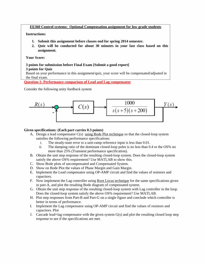
Question-1: Performance comparison of Lead and Lag compensator
Consider the following unity feedback system
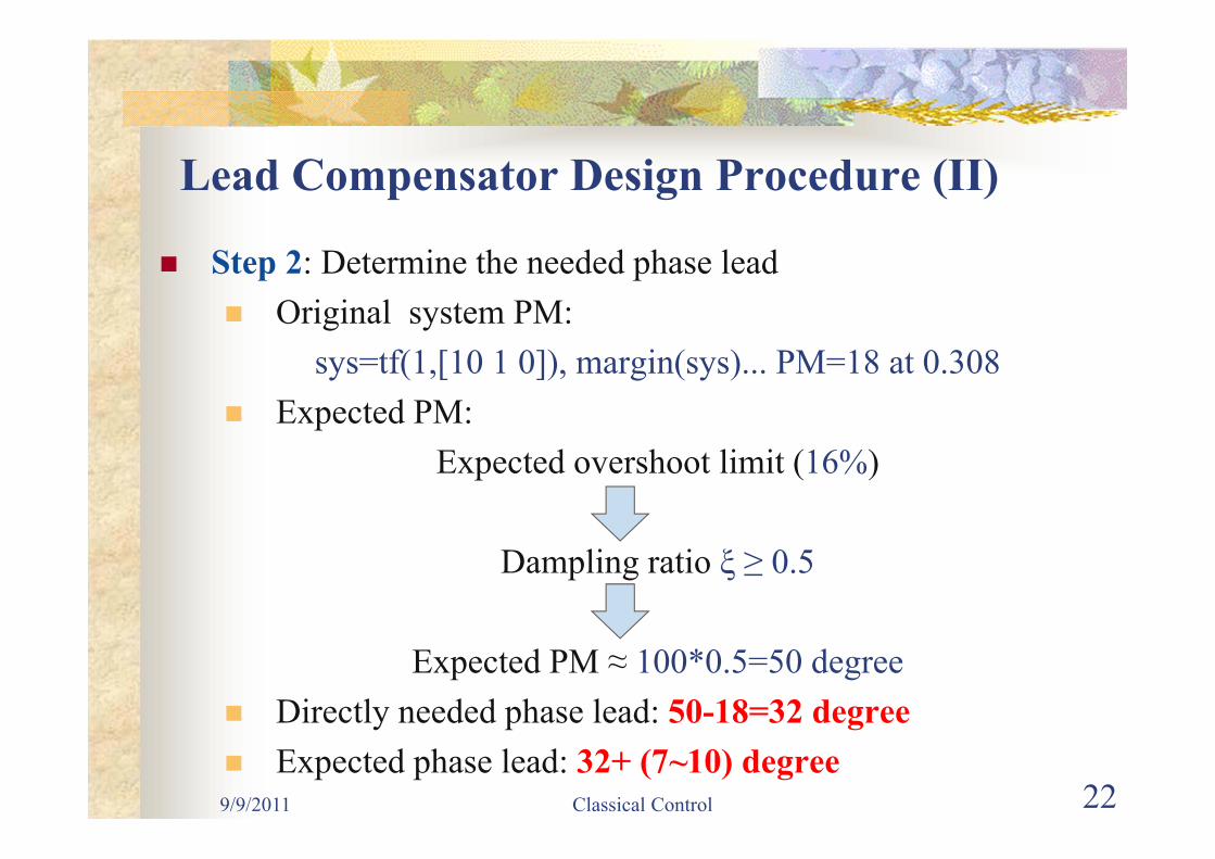
Given specifications: (Each part carries 0.3 points)A. Design a lead compensator C(s) using Bode Plot technique so that the closed-loop system
satisfies the following performance specifications:i. The steady-state error to a unit-ramp reference input is less than 0.01.
ii. The damping ratio of the dominant closed-loop poles is no less than 0.4 or the OS% nomore than 25% (Transient performance specification).
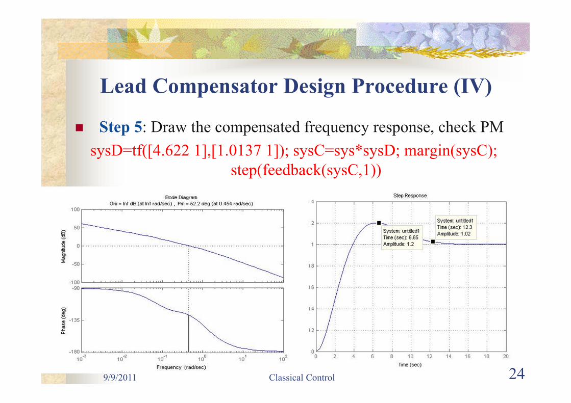
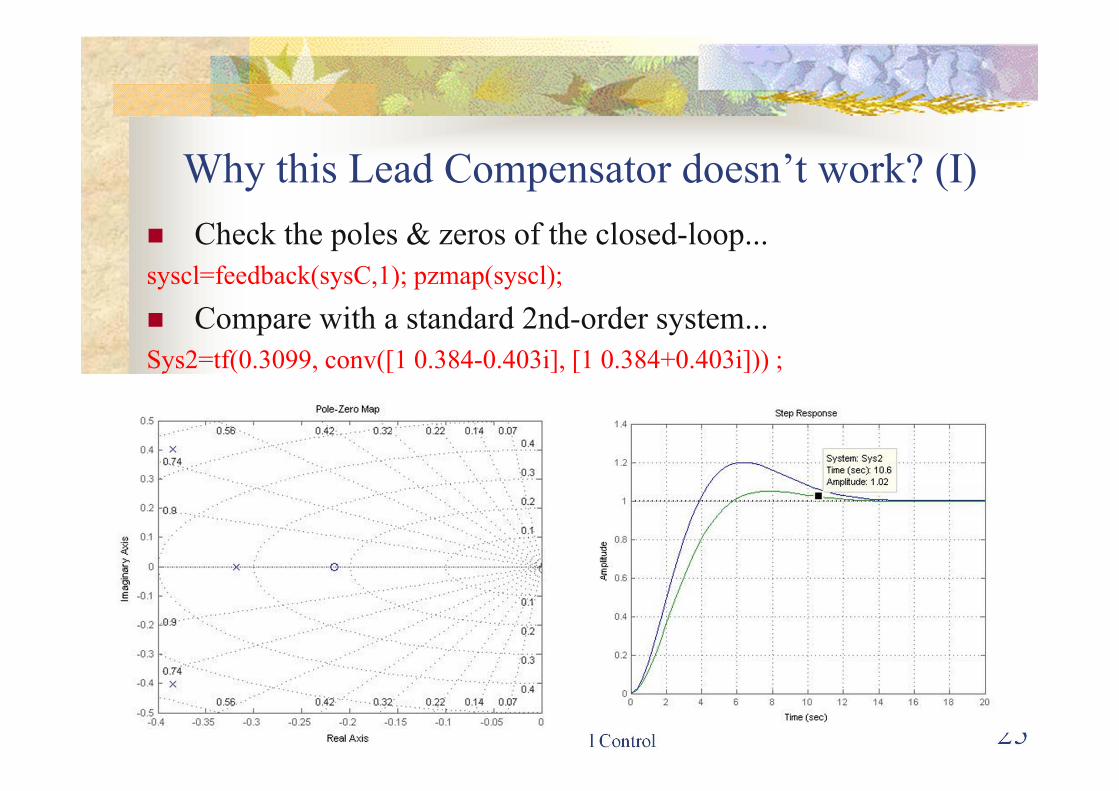
B. Obtain the unit step response of the resulting closed-loop system. Does the closed-loop systemsatisfy the above OS% requirement? Use MATLAB to show this.
C. Show Bode plots of uncompensated and Compensated System.D. Show on Bode Plot the values of Phase Margin and Gain Margin.E. Implement the Lead compensator using OP-AMP circuit and find the values of resistors and
capacitors.F. Now implement the Lag controller using Root Locus technique for the same specifications given
in part-A, and plot the resulting Bode diagram of compensated system.G. Obtain the unit step response of the resulting closed-loop system with Lag controller in the loop.
Does the closed-loop system satisfy the above OS% requirement? Use MATLAB.H. Plot step responses from Part-B and Part-G on a single figure and conclude which controller is
better in terms of performance.I. Implement the Lag compensator using OP-AMP circuit and find the values of resistors and
capacitors. PlotJ. Cascade lead+lag compensator with the given system G(s) and plot the resulting closed loop step
response to see if the specifications are met.
9/9/2011 Classical Control 15
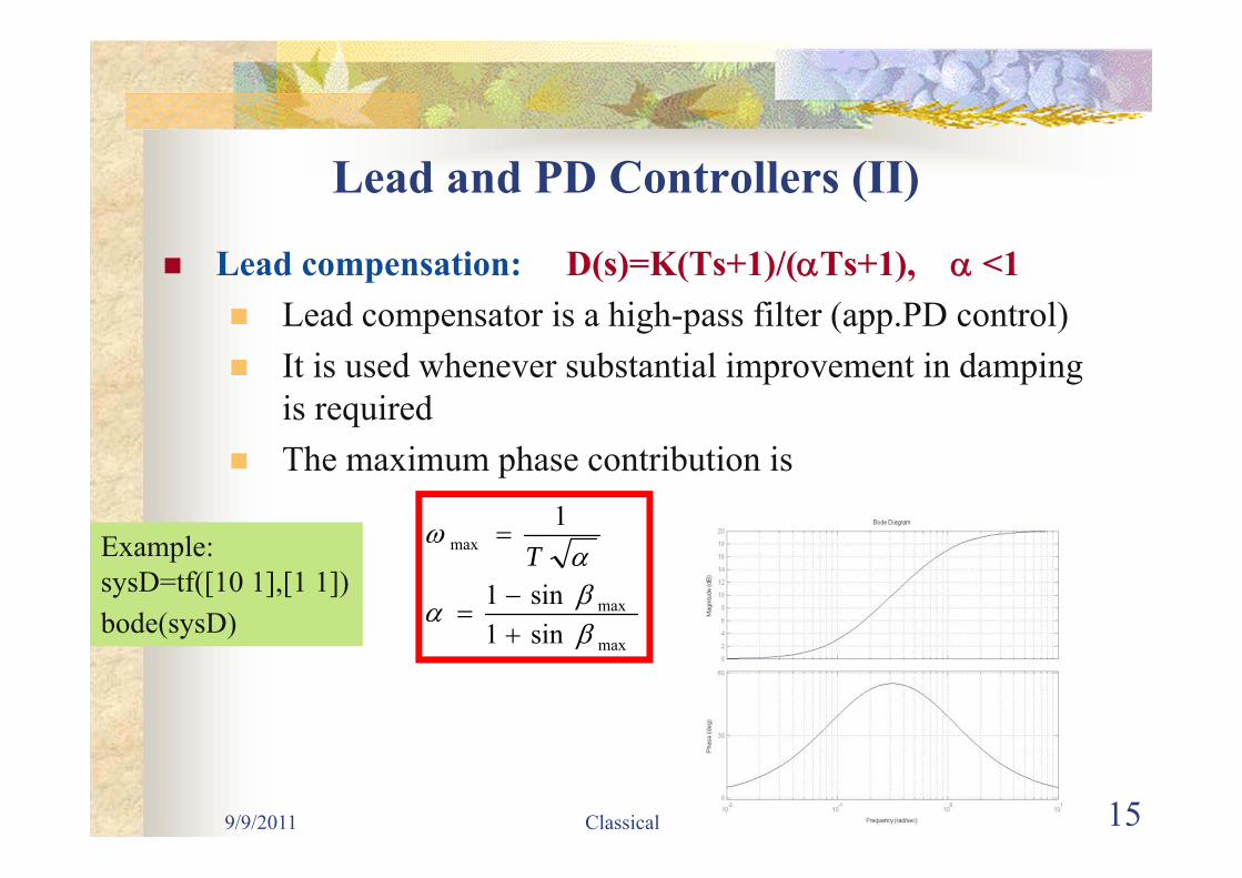
Lead and PD Controllers (II)
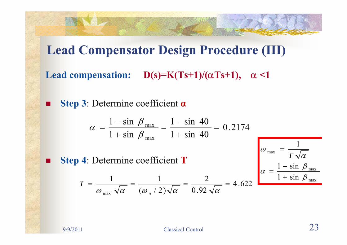
Lead compensation: D(s)=K(Ts+1)/(Ts+1), <1 Lead compensator is a high-pass filter (app.PD control) It is used whenever substantial improvement in damping
is required The maximum phase contribution is
max
max
max
sin1sin1
1
TExample:
sysD=tf([10 1],[1 1])bode(sysD)
9/9/2011 Classical Control 16
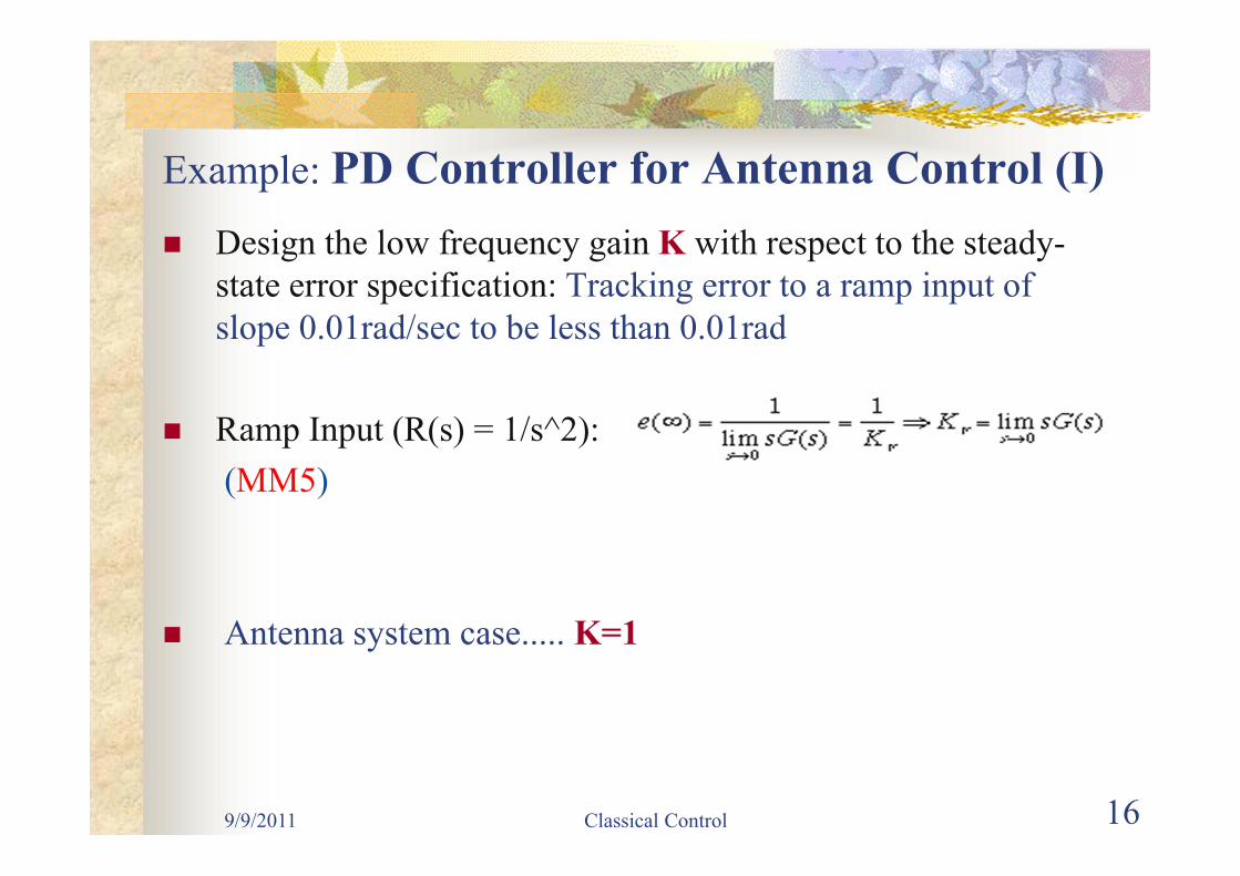
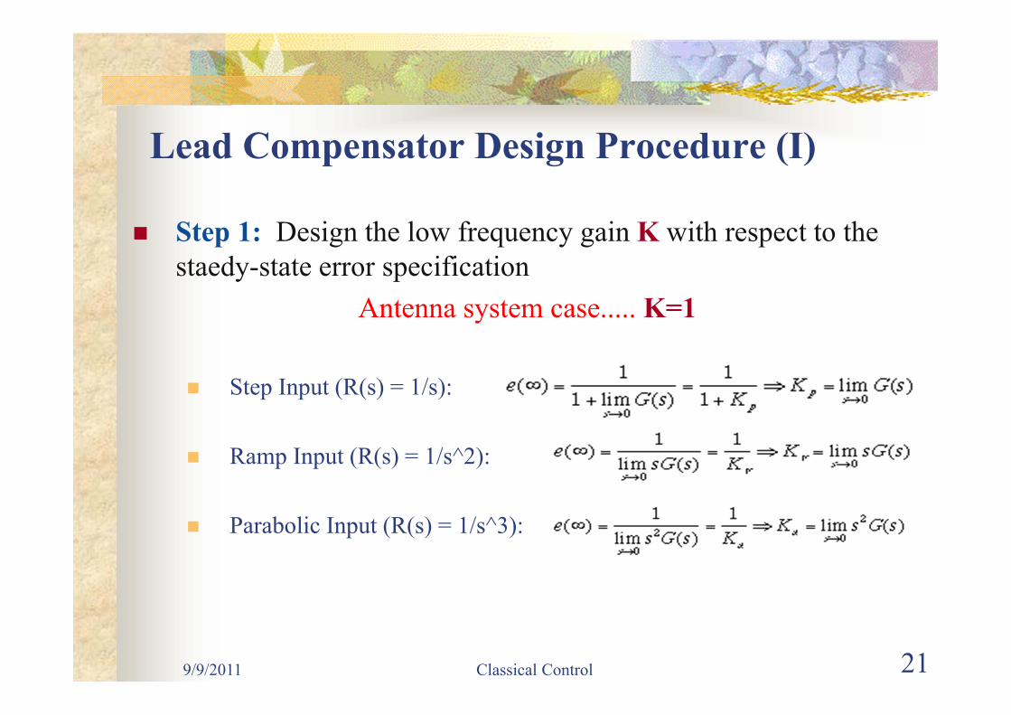
Example: PD Controller for Antenna Control (I) Design the low frequency gain K with respect to the steady-
state error specification: Tracking error to a ramp input of slope 0.01rad/sec to be less than 0.01rad
Ramp Input (R(s) = 1/s^2): (MM5)
Antenna system case..... K=1
9/9/2011 Classical Control 17
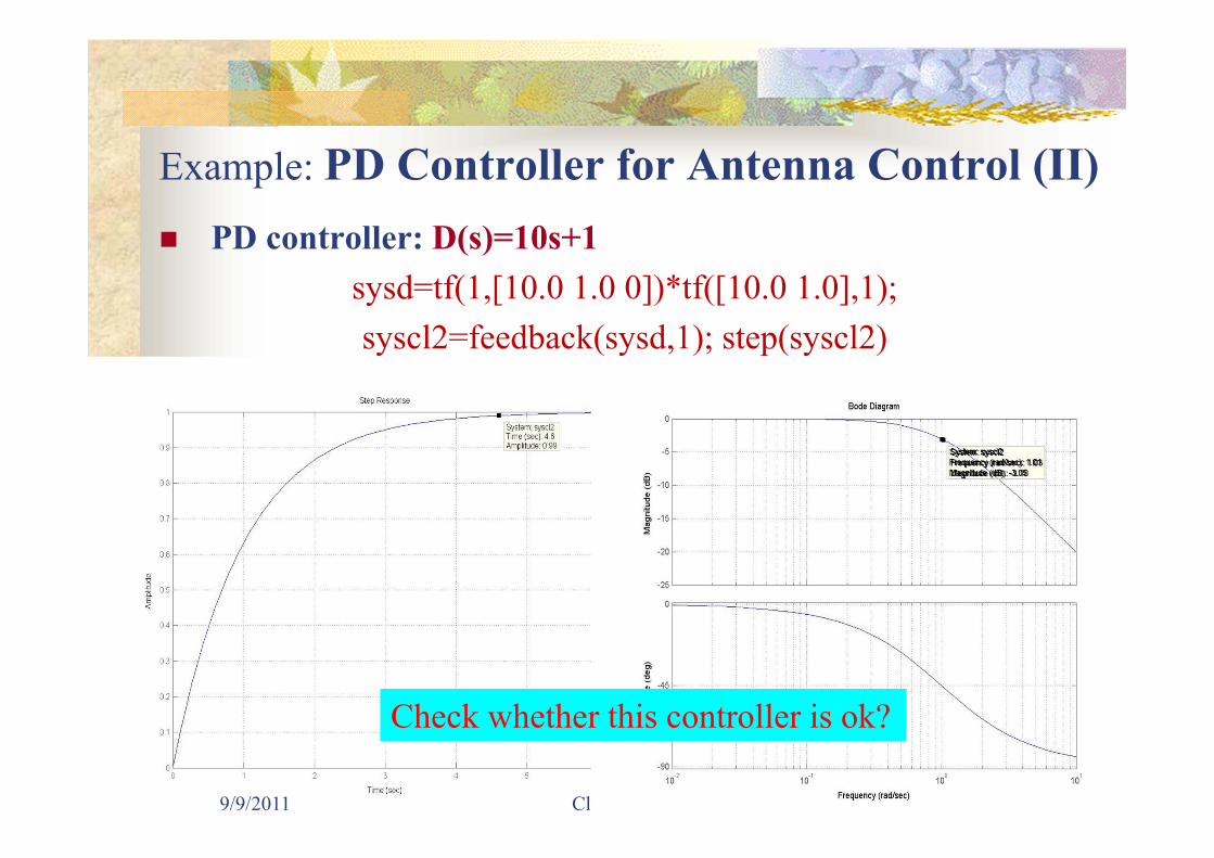
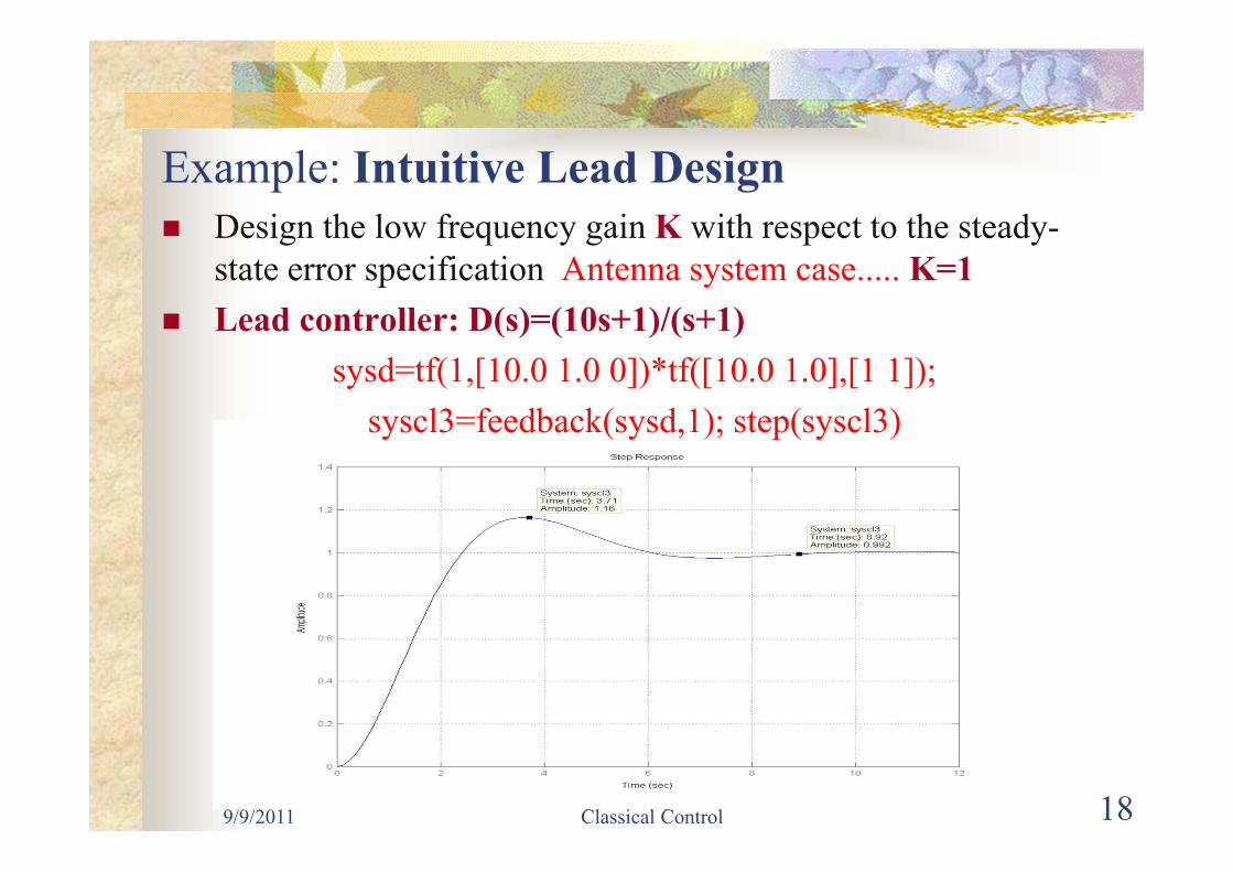
Example: PD Controller for Antenna Control (II) PD controller: D(s)=10s+1