Heating of active elements �AE� of solid-state lasersgives rise to the temperature gradient, initiating, ow-ing to the photoelastic effect, the birefringence inisotropic crystals and glasses.1 In this case the di-rection of eigen �normal� polarizations, as well as thephase shift between them �value of birefringence�,have a nonuniform cross-section distribution. Thisleads to the depolarization; being constant in time,polarization varies from point to point of the crosssection. The problem of compensation of the depo-larization in AE has been studied for a long time andremains the subject of investigations. Moreover, be-cause of the recent increase in the average laserpower, this problem becomes ever more topical.
Various methods have been used to diminish theinfluence of these undesired effects �birefringenceand depolarization�, but these methods are not allflawless. It is possible to control the birefringenceitself through use of AEs not as rods but rather asslabs or discs1 and through application of additionallongitudinal2 or transverse3 mechanical stress.However, this adds complexity to the geometry of thelaser head and makes heat removal more difficult.
The authors are with the Institute of Applied Physics, 46 Ul-janov Street, North Novgorod, Russia 603950. E. A. Khazanovcan be reached at [email protected].
Received 6 August 2001; revised manuscript received 2 January2002.
The recently proposed4 use of a geometrically diver-gent beam in a uniaxial crystal requires perfect align-ment.
Other methods rely on the idea of subtracting thephase shift by means of the same or another similarAE. The use of two identical AEs and a 90° rotatorplaced between them was suggested first in Ref. 5and has been employed frequently ever since. Thealignment accuracy and requirements for identity ofthe AEs were studied in detail in Ref. 6. Thanks toan image relay this method can be used effectivelydespite the large thermal lens.7 However, it is oftennot so easy to find two identical AEs. Furthermore,the use of another AE solely for compensation of thebirefringence seems to be unpractical.
The subtraction of phase incursion can be madewith high accuracy with a phase conjugate mirrorduring a backward pass through the same AE.8,9
However, the nonlinear methods are not efficient inlasers with moderate peak powers. A ��4 plate anda conventional mirror10 can compensate for the depo-larization only when heat release in AE is small.11–13
Porro prisms require special dielectric coatings to beapplied onto an internally reflecting surface.1,14 Thefabrication of parallel axicon15 is fairly costly.
The Faraday mirror �FM�, a combination of a 45o
Faraday rotator and a mirror �the dashed rectangle inFig. 1� has long and very effectively been used to com-pensate for the birefringence in laser amplifiers,16–19
oscillators,20 and regenerative amplifiers.21 How-ever, at high average powers the FM itself inserts thedepolarization owing to an absorption of radiation inthe magneto-optical medium.13,21–23 This reduces
the effectiveness of compensation of the birefringencein AE.13 Calculations show that the use of the re-cently developed designs of the Faraday isolator forhigh average powers23–25 in FM is ineffective. InRef. 13 a novel FM that does not insert depolarizationeven at considerably high powers of radiation hasbeen suggested and theoretically investigated.However, this FM has not been checked experimen-tally.
Usually, the polarization incident on AE is linear.At the same time, at small average power, propertiesof FM enable the compensation of the depolarizationin AE at any ellipticity of incident polarization.Therefore by varying incident polarization one canminimize the residual depolarization at high averagepower. In this paper we find an optimal incidentpolarization for both the novel and the traditional FMand study experimentally the FM at different inci-dent polarizations.
2. Influence of the Ellipticity on Faraday MirrorOperation
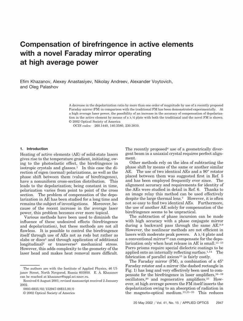
The effectiveness of the compensation of depolariza-tion in AE with the traditional and novel FM for thecase of linear polarization incident on the AE �part aof Fig. 1� was studied theoretically in Ref. 13. In theabsence of any parasitic effects in the FM �e.g., ther-mally induced birefringence�, both mirrors compen-sate for the depolarization in AE not only at the linearincident polarization but also at an arbitrary polar-ization. This means that the influence of thermaleffect in FM on the accuracy of the compensation maydepend on the incident polarization; therefore it isimportant to find an optimal incident polarization.As this task has no specified directions, it is evidentthat there may be no dependence on the direction ofthe ellipse axis of the polarization. Therefore it isreasonable to vary the ellipticity only. To do this, itis convenient to place a ��4 plate before the AE �partb of Fig. 1�. In this case the ellipticity of polarizationincident on the AE will vary from 0 to 1, depending onthe angle �1 between axes of the plate and the polar-izer �an angle of the polarization ellipticity is equalprecisely to �1 in this case�. Analogous consider-ations are also appropriate for a ��4 plate that is
placed between the AE and the FM �part c of Fig. 1�with an angle �2 between the axes of the plate and thepolarizer.
Let us define the effectiveness of the birefringencecompensation in AE, taking into account the ther-mally induced birefringence in FM, for opticalschemes presented in parts b and c of Fig. 1; thescheme in part a in Fig. 1 was discussed in detail inRef. 13. First of all, let us determine the Jones ma-trices for all optical elements.
Let us suppose that the distribution of pump powerand, therefore, of heat release in AE is uniform overthe volume. Then for an infinitely long cylindricalAE with the �111� crystal orientation �for other ori-entations, see Ref. 26�, having the coefficient of fieldgain K0, the matrix A has the form27
A � K0 sin�a
2 �ctg�a
2� i cos 2� � i sin 2�
� i sin 2� ctg�a
2� i cos 2�� ,
(1)
where
�a �r2
r02 pa,
a �2pa44
pa11 � pa12,
Qa � � 1La
dLa
dT � na3
41 � va
1 � va� pa11 � pa12�,
pa �1�
Qa
a
1 � 2a
6r0
2
R2 Pa, (2)
where �a, a, na, pai,j, La, and R are the Poisson’s ratio,the thermal conductivity, the refraction index, andthe photoelastic coefficients in Nye’s convention28 andthe length and the radius of AE; T is the temperature;� is a wavelength; Pa is the power of heat release inAE; and r,� are polar coordinates. These same ex-pressions are also valid for glass AEs, for which a �
Fig. 1. Compensation of birefringence in AE with the traditional and new FM designs. P, polarizer; FR, Faraday element � , angle ofrotation of polarization plane�; QR, 90° quartz polarization rotator; M, mirror.
1. Further we shall not consider the effect of gainsaturation in AE and shall assume K0 � const.
Now to determine the matrix of the FM Mold,new wewill limit the consideration to two most commonlyused orientations of the cubic crystal – �001� and�111� �for other orientations, see Ref. 26�. In thiscase Mold,new has the form13
Mold � F���4, �l� F���4, �l�, (3)
Mnew � F���6, 2�l�3� R�F���12, �l�3�
� F���12, �l�3� R�F���6, 2�l�3�, (4)
where
R� � � 0 �1�1 0 � ,
F� , �l� �
sin�
2 �ctg�
2� i
�l
�cos 2� �
2
�� i
�l
�sin 2�
2
�� i
�l
�sin 2� ctg
�
2� i
�l
�cos 2� � ,
(5)
�2 � �l2 � �c
2, (6)
�l � 2p�r02 1 � exp� � r2�r0
2�
r2 � 1� 1 � 2
3,
�c � 2 ,
�2p44
p11 � p12, (7)
p �L�
�Q
P0, (8)
Q � �1L
dLdT� n0
3
41 � v1 � v
� p11 � p12�,
where �, , �, n0, pi,j, and L are the Poisson’s ratio, thethermal conductivity, the absorption coefficient, therefraction index, the photoelastic coefficients, and thelength of the magneto-optical medium; P0 is thepower of laser radiation at a point B or C �because ofsmall absorption in the magneto-optical medium, weconsider these powers to be identical�. Here and fur-ther subscripts “old” and “new” will refer to the tra-ditional and novel FM. Equations �5� and �6� arevalid also for glass Faraday elements, for which � 1.
Let us assume that at a point A the field EA has aGaussian distribution of intensity with an amplitudeE0 and radius r0 and is polarized along the x axis
EA � x0E0 exp� �r2
2r02� , (9)
where x0 is a unit vector directed along the x axis.Then during the return pass at a point D the field is
determined through Jones matrices of AE �Eq. �1��, ofFM �Eqs. �3� and �4��, and of ��4 plate L4 ���:
Eold,new � AMold,newAEA,
E1old,new � L4��1� AMold,newAL4��1�EA,
E2old,new � AL4��2� Mold,newL4��2� AEA. (10)
Here and henceforth subscripts 1 and 2 refer to Figs.1�b� and 1�c�.
The inaccuracy of birefringence compensation inthe AE is characterized by the depolarization ratio �,a ratio of the power that is transmitted through thepolarizer in the backward direction to the total powerat point D,
� � �0
2�
d� �0
�
�E � x0�2 rdr��0
2�
d� �0
�
�E�2 rdr��1
.
(11)
We suppose that the clear apertures of the Faradayrotator and AE are such that the aperture losses canbe ignored and the integration in Eq. �8� over r can beextended to infinity. Let us discuss the case inwhich linear birefringence in the magneto-opticalmedium is small, i.e.,
�l �� 1. (12)
In this approximation, the substitution of Eqs. �1�,�3�, �4�, and �9� in Eq. �10�, and then substitution ofthat result in Eq. �11�, followed by an integration thattakes into account inequality �12�, yields the expres-sion for the depolarization ratio:
Thus in all cases the depolarization ratio is deter-mined by parameters pa, the normalized power ofheat release in the AE �Eq. �2��; p, the normalizedpower of laser radiation in the FM �Eq. �8��; , acombination of photoelastic coefficients of themagneto-optical medium �Eq. �7��; and an inclinationangle of the ��4 plate �1,2.
At �1 � 0 expressions for �old,new coincide with theexpressions for the scheme in part a of Fig. 1 obtainedin Ref. 13. It is clear that at �1 � 0 the depolariza-tion ratio in schemes on parts a and b of Fig. 1 will beidentical.
In the absence of birefringence in the AE �at pa �0� the depolarization ratio in case of the use of theFaraday rotator is nonzero. Since f1,2�pa � 0� � 0,from Eqs. �13�–�16� we obtain identical expressionsfor �1 and �2,
�old1� pa � 0� � �old2� pa � 0�
�8�2 p2�1 � 2
3 �2
� A1�1 � sin2 2�1, 2�,
�new1� pa � 0� � �new2� pa � 0�
� �23 � ��2 p4
2�4 �1 � 2
3 �4
� A22 cos2 2�1, 2, (19)
that describe the dependence of the depolarizationin FM itself on p and �. These expressions may beuseful when other applications of FM not related tothe compensation of birefringence on the AE areanalyzed.
At the same time, large values of pa are of moreinterest from a practical point of view. It can beeasily shown that in all cases, when the depolariza-tion ratio is increased it comes quickly to saturationand tends to be a constant. Therefore at large bire-fringence in AE it is convenient to characterize all
designs for compensation by this value. From Eqs.�17� and �18� it is seen that f1,2 �pa3�� � 0.5A1,2.Taking this into account, from Eqs. �13�–�16� we ob-tain
�old1� pa3 �� �4�2 p2 �1 � 2
3 �2
A1�2 � cos2 2�1�,
�old2� pa3 �� �232�2 p2 �1 � 2
3 �2
A1,
�new1� pa3 �� � �23 � ��2 4p4
�4 �1 � 2
3 �4
� A2�2 � 2 cos2 2�1�,
�new2� pa3 �� � �23 � ��2 p4
�4 �1 � 2
3 �4
� A2�13 � 6 sin2 2�2�. (20)
In conclusion, we will generalize the results for thecase of a Gaussian profile of heat release in AE and asuper-Gaussian laser beam profile. Let the volumedensity of heat release power in AE be uniform alongthe length and have a Gaussian profile with Pa�0� inmaximum and radius rp. As stated previously, Pa isthe total power of heat release, i.e., Pa � �rp
2Pa�0�La.In this case, the expression for matrix of AE may betaken from Ref. 4. It is clear that the result willdepend on parameter
� �r0
2
rp2 ,
a square of the ratio between radii of the beam andthe pump. The above uniform distribution of pump-ing is a particular case at � � 0. Actual distributionof heat release in the AE is determined by the type ofpumping: It is close to Gaussian under end pump-ing and nearly uniform under side pumping.
Let us consider a super-Gaussian beam
EA � x0E0 exp� �r2m
2r02m� .
Parameter m characterizes the speed of intensitydropping. At m � 1, the intensity drops relativelyslowly �a Gaussian beam�. As m increases, thespeed of intensity dropping increases, and at m � �the beam becomes flat shaped. Since the beamshape determines the distribution of the heat releasedensity in the magneto-optical medium, this willchange the expression for �l in Eq. �6�. This wasdiscussed more thoroughly in Ref. 29.
Calculations for Gaussian pumping and a super-Gaussian beam show that Eqs. �13�–�16� and �19, 20�
are valid if Eqs. �2�, �17�, and �18� are replaced, re-spectively, by
pa �Qa
�a
1 � 2a
12�1 � exp� � 2���Pa, (21)
fn � pa� �1
�1�2n �0
� �y�1 �0
y
dz �0
z
exp� � ym�dy�2n
� exp��ym�sin2
� �4pa
�y � 1 � exp���y�
�y�1�exp��2��� �dy, (22)
An � An�m� �1
�1�2n �0
� �y�1 �0
y
dz �0
z
exp
� � � ym�dy�2n
exp��ym�dy, (23)
where
� � �0
�
exp� � ym�dy.
At � � 0 and m � 1 Eqs. �21�–�23� transform into Eqs.�2�, �17�, and �18�.
3. Experimental Results
The aim of these experiments was twofold: first, tocheck the effectiveness of the compensation of depo-larization in AE at high average power with the novelFM and second, to verify the theoretical results thatwere discussed in Section 2.
A schematic of our experimental setup is shown inFig. 2. We used linearly polarized radiation from acw Nd:YLF laser �Photonics Industries, Bohemia,New York� with a near-Gaussian beam �m � 1�. Thelaser beam was used to create a heat source in theglass sample and, simultaneously, to measure thedepolarization �� � 1�. A calcite wedge served as apolarizer. A 5-cm sample made of TK21 glass ab-sorbed 4.3% of the radiation, thereby imitating anAE. Then the beam came to a FM based on amagneto-optical glass MOC15–35 and permanent
magnets. Two optical elements 27 and 13.5 mm inlength rotated the polarization by 30° and 15°. Forcorrect comparison of the traditional and novel FMwe used the same two optical elements in the novelFM, but without the 90o quartz rotator betweenthem.
Upon the backward pass of the beam through thesample the depolarization ratio � was measured withpower meters, depending on the power of laser radi-ation. Additionally, a telescope was placed in theFM to compensate for the thermal lens of the sampleand the Faraday elements. The distance betweenthe telescope lenses was adjusted for each powervalue. In addition, at any power we compensatedthe decrease in the Verdet constant caused by a heat-ing of the magneto-optical medium by moving Fara-day elements inside the magnet system.
Figure 3 demonstrates the results of the experi-ments. The solid line indicates the theoretical curveplotted by Eq. �13� at �1 � 0. The values �0.51WK�1m�1 and Q � 6 � 10�7K�1 were taken fromRef. 30, whereas the absorption coefficient � was usedas a fit parameter and was � � 0.003 � 0.001cm�1.Note that this value is greater than that reported inRef. 31.
Although absolute values of the depolarization ra-tio with the new FM are much less than those withthe traditional FM, they exceed those predicted byEq. �15�. At small powers ��10W� this may be ex-plained by “cold” depolarization in the magneto-
Fig. 2. Experimental scheme. cw, calcite wedge; GS, glass sample; FR, Faraday element � , angle of rotation of polarization plane�; M,mirror; PM1, powermeter of depolarized component; PM2, powermeter of polarized component; L1, L2, telescopes.
Fig. 3. Depolarization ratio vs power: AE without compensation�squares�, traditional FM without AE �filled circles, straight line�,traditional FM and AE �filled triangles�, new FM without AE �opencircles�, and new FM with AE �open triangles�.
optical glass, while at high powers by an insufficientcompensation of the thermal lens. Owing to the lat-ter, beams during the forward and backward passtravel slightly different trajectories, reducing the ef-fectiveness of the compensation of the depolarizationin both the AE and the FM.
The dependence of the depolarization ratio insertedby the FM without the AE on the polarization ofincident radiation was studied experimentally. At aconstant power of radiation the ellipticity was variedwith a ��4 plate, whereas the inclination angle of theellipse was varied with a ��2 plate placed after the��4 plate. It turned out that within the accuracy ofmeasurement error the depolarization ratio is inde-pendent of the inclination angle of the ellipse at anyellipticity and radiation power, and also for any FMdesign. This agrees with theoretical predictions �seeabove�.
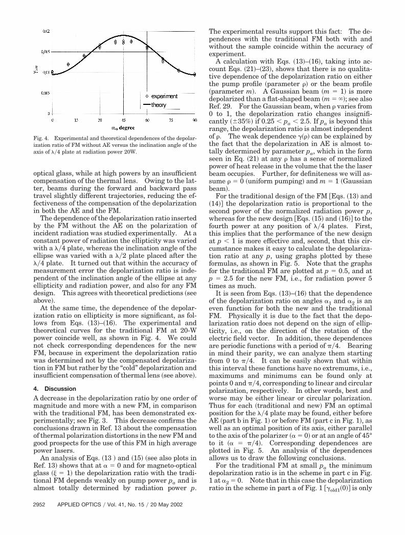
At the same time, the dependence of the depolar-ization ratio on ellipticity is more significant, as fol-lows from Eqs. �13�–�16�. The experimental andtheoretical curves for the traditional FM at 20-Wpower coincide well, as shown in Fig. 4. We couldnot check corresponding dependences for the newFM, because in experiment the depolarization ratiowas determined not by the compensated depolariza-tion in FM but rather by the “cold” depolarization andinsufficient compensation of thermal lens �see above�.
4. Discussion
A decrease in the depolarization ratio by one order ofmagnitude and more with a new FM, in comparisonwith the traditional FM, has been demonstrated ex-perimentally; see Fig. 3. This decrease confirms theconclusions drawn in Ref. 13 about the compensationof thermal polarization distortions in the new FM andgood prospects for the use of this FM in high averagepower lasers.
An analysis of Eqs. �13 � and �15� �see also plots inRef. 13� shows that at � � 0 and for magneto-opticalglass � � 1� the depolarization ratio with the tradi-tional FM depends weakly on pump power pa and isalmost totally determined by radiation power p.
The experimental results support this fact: The de-pendences with the traditional FM both with andwithout the sample coincide within the accuracy ofexperiment.
A calculation with Eqs. �13�–�16�, taking into ac-count Eqs. �21�–�23�, shows that there is no qualita-tive dependence of the depolarization ratio on eitherthe pump profile �parameter �� or the beam profile�parameter m�. A Gaussian beam �m � 1� is moredepolarized than a flat-shaped beam �m � ��; see alsoRef. 29. For the Gaussian beam, when � varies from0 to 1, the depolarization ratio changes insignifi-cantly ��35%� if 0.25 � pa � 2.5. If pa is beyond thisrange, the depolarization ratio is almost independentof �. The weak dependence ���� can be explained bythe fact that the depolarization in AE is almost to-tally determined by parameter pa, which in the formseen in Eq. �21� at any � has a sense of normalizedpower of heat release in the volume that the the laserbeam occupies. Further, for definiteness we will as-sume � � 0 �uniform pumping� and m � 1 �Gaussianbeam�.
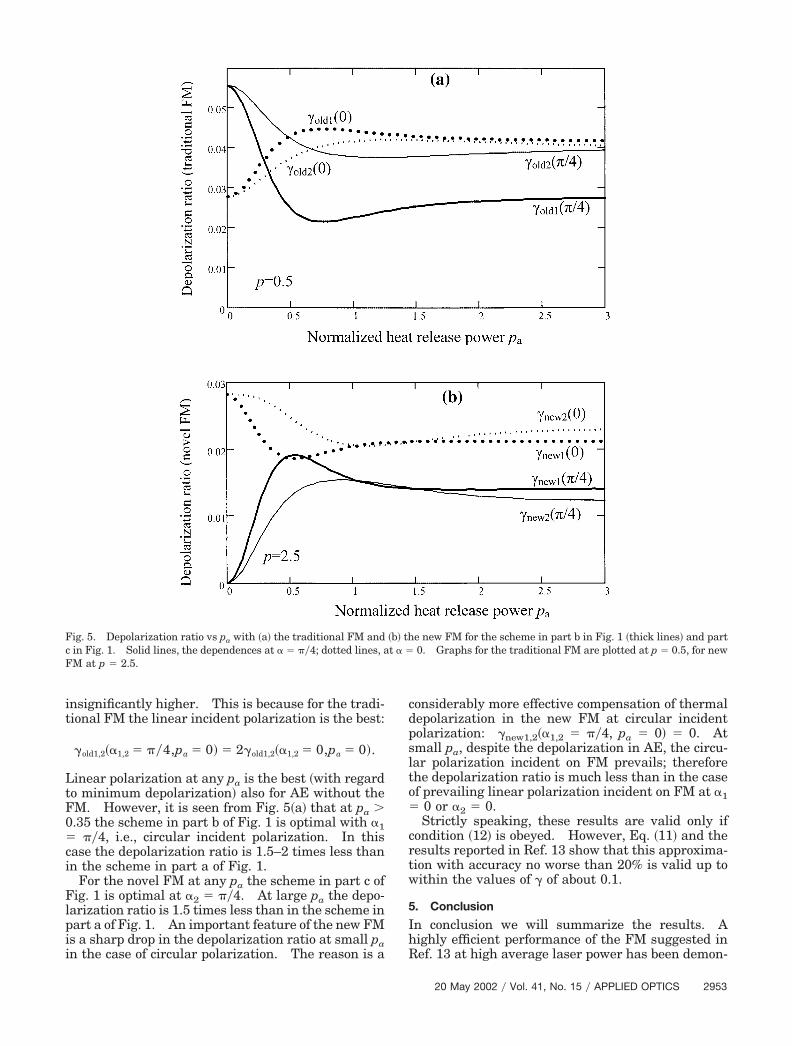
For the traditional design of the FM �Eqs. �13� and�14�� the depolarization ratio is proportional to thesecond power of the normalized radiation power p,whereas for the new design �Eqs. �15� and �16�� to thefourth power at any position of ��4 plates. First,this implies that the performance of the new designat p � 1 is more effective and, second, that this cir-cumstance makes it easy to calculate the depolariza-tion ratio at any p, using graphs plotted by theseformulas, as shown in Fig. 5. Note that the graphsfor the traditional FM are plotted at p � 0.5, and atp � 2.5 for the new FM, i.e., for radiation power 5times as much.
It is seen from Eqs. �13�–�16� that the dependenceof the depolarization ratio on angles �1 and �2 is aneven function for both the new and the traditionalFM. Physically it is due to the fact that the depo-larization ratio does not depend on the sign of ellip-ticity, i.e., on the direction of the rotation of theelectric field vector. In addition, these dependencesare periodic functions with a period of ��4. Bearingin mind their parity, we can analyze them startingfrom 0 to ��4. It can be easily shown that withinthis interval these functions have no extremums, i.e.,maximums and minimums can be found only atpoints 0 and ��4, corresponding to linear and circularpolarization, respectively. In other words, best andworse may be either linear or circular polarization.Thus for each �traditional and new� FM an optimalposition for the ��4 plate may be found, either beforeAE �part b in Fig. 1� or before FM �part c in Fig. 1�, aswell as an optimal position of its axis, either parallelto the axis of the polarizer �� � 0� or at an angle of 45°to it �� � ��4�. Corresponding dependences areplotted in Fig. 5. An analysis of the dependencesallows us to draw the following conclusions.
For the traditional FM at small pa the minimumdepolarization ratio is in the scheme in part c in Fig.1 at �2 � 0. Note that in this case the depolarizationratio in the scheme in part a of Fig. 1 ��old1�0�� is only
Fig. 4. Experimental and theoretical dependences of the depolar-ization ratio of FM without AE versus the inclination angle of theaxis of ��4 plate at radiation power 20W.
Linear polarization at any pa is the best �with regardto minimum depolarization� also for AE without theFM. However, it is seen from Fig. 5�a� that at pa �0.35 the scheme in part b of Fig. 1 is optimal with �1� ��4, i.e., circular incident polarization. In thiscase the depolarization ratio is 1.5–2 times less thanin the scheme in part a of Fig. 1.
For the novel FM at any pa the scheme in part c ofFig. 1 is optimal at �2 � ��4. At large pa the depo-larization ratio is 1.5 times less than in the scheme inpart a of Fig. 1. An important feature of the new FMis a sharp drop in the depolarization ratio at small pain the case of circular polarization. The reason is a
considerably more effective compensation of thermaldepolarization in the new FM at circular incidentpolarization: �new1,2��1,2 � ��4, pa � 0� � 0. Atsmall pa, despite the depolarization in AE, the circu-lar polarization incident on FM prevails; thereforethe depolarization ratio is much less than in the caseof prevailing linear polarization incident on FM at �1� 0 or �2 � 0.
Strictly speaking, these results are valid only ifcondition �12� is obeyed. However, Eq. �11� and theresults reported in Ref. 13 show that this approxima-tion with accuracy no worse than 20% is valid up towithin the values of � of about 0.1.
5. Conclusion
In conclusion we will summarize the results. Ahighly efficient performance of the FM suggested inRef. 13 at high average laser power has been demon-
Fig. 5. Depolarization ratio vs pa with �a� the traditional FM and �b� the new FM for the scheme in part b in Fig. 1 �thick lines� and partc in Fig. 1. Solid lines, the dependences at � � ��4; dotted lines, at � � 0. Graphs for the traditional FM are plotted at p � 0.5, for newFM at p � 2.5.
strated experimentally. A decrease in the depolar-ization ratio by more than one order of magnitude incomparison with the traditional mirror has beenachieved. It is shown that the accuracy of compen-sation of depolarization in the AE by means of a ��4plate may be increased with both the traditional andnew FM.
This work was supported by grant PHY-9900786from the U.S. National Science Foundation and grant99–02-17257 from the Russian Foundation for BasicResearch.
References1. W. Koechner, Solid-State Laser Engineering �Springer, New
York, 1999�.2. Y. Liao, R. J. D. Miller, and M. R. Armstrong, “Pressure tuning
of thermal lensing for high-power scaling,” Opt. Lett. 24, 1343–1345 �1999�.
3. E. Khazanov, N. Andreev, O. Palashov, and D. Reitze, “Use ofmechanical stress in design of a Faraday isolator for highpower radiation,” in Conference on Lasers and Electro-Optics�CLEO�, Postdeadline papers, Vol. 39 of OSA Trends in Opticsand Photonics �Optical Society of America, Washington, D.C.,2000�, pp. 321–322.
4. E. Khazanov, A. Poteomkin, and E. Katin, “Novel method forcompensating birefringence in active elements of solid-statelasers,” J. Opt. Soc. Am. B 41, 667–671 �2002�.
5. W. C. Scott and M. de Wit, “Birefringence compensation andTem00 mode enhancement in a Nd:YAG laser,” Appl. Phys.Lett. 18, 3–4 �1971�.
6. N. Kugler, S. Dong, Q. Lu, and H. Weber, “Investigation of themisalignment sensitivity of a birefringence-competed two-rodNd:YAG laser system,” Appl. Opt. 36, 9359–9366 �1997�.
7. N. Andreev, N. G. Bondarenco, I. V. Eremina, E. Khazanov,S. V. Kuznetsov, O. Palashov, and G. Pasmanik, “A single-mode YAG:Nd laser with an SBS mirror and conversion of theradiation to the second and fourth harmonics,” Sov. J. Quan-tum Electron. 21, 1045–1050 �1991� �Kvant. Electron. 18,1154–1160 �1991��.
8. N. F. Andreev, A. A. Babin, E. A. Khazanov, S. B. Paperny, andG. A. Pasmanik, “Pulse-repetition solid-state laser with SBS-cells,” Laser Phys. 2, 1–19 �1992�.
9. D. A. Rockwell, “A review of phase-conjugate solid-state laser,”IEEE J. Quantum Electron. 24, 1124–1140 �1988�.
10. W. A. Clarkson, N. S. Felgate, and D. C. Hanna, “Simplemethod for reducing the depolarization loss resulting fromthermally induced birefringence in solid-state lasers,” Opt.Lett. 24, 820–822 �1999�.
11. R. Hua, S. Wada, and H. Tashiro, “Principles and limitationsof a quarter-wave plate for reducing the depolarization lossfrom thermally induced birefringence in Nd:YAG Lasers,” Opt.Commun. 175, 189–200 �2000�.
12. R. Kandasamy, M. Yamanaka, Y. Izawa, and S. Nakui, “Anal-ysis of birefringence compensation using a quarter-wave platein solid-state lasers,” Opt. Rev. 7, 149–151 �2000�.
13. E. A. Khazanov, “New Faraday rotator for high average powerlasers,” Quantum Electron. 31, 351–356 �2001� �Kvant. Elec-tron. 31, 351–356 �2001��.
14. E. A. Lundstrom, “Waveplate for correcting thermally inducedstress birefringence in solid state lasers,” U.S. patent4,408,334 �4 Oct. 1983�.
15. E. A. Khazanov, “A novel technique for compensation of bire-fringence in active elements of solid-state lasers,” in Confer-
ence on Lasers and Electro-Optics �CLEO�, Vol. 56 of OSATrends in Optics and Photonics �Optical Society of America,Washington, D.C., 2001�, pp. 528–529.
16. G. Giuliani and P. Ristori, “Polarization flip cavities: a newapproach to laser resonators,” Opt. Commun. 35, 109–112�1980�.
17. M. Martinelly, “A universal compensator for polarizationchanges induced birefringence on a retracing beam,” Opt.Commun. 72, 341–344 �1989�.
18. N. Andreev, S. V. Kuznetsov, O. Palashov, G. Pasmanik, andE. Khazanov, “Four-pass YAG:Nd laser amplifier with com-pensation for aberration and polarization distortions of thewave front,” Sov. J. Quantum Electron. 22, 800–802 �1992��Kvant. Electron. 19, 862–802 �1992��.
19. N. Andreev, E. Khazanov, O. Kulagin, B. Movshevich, O. Pa-lashov, G. Pasmanik, V. Rodchenkov, A. Scott, and P. Soan, “Atwo-channel repetitively pulsed Nd:YAG laser operating at 25Hz with diffraction-limited beam quality,” IEEE J. QuantumElectron. 35, 110–114 �1999�.
20. K. S. Lai, R. Wu, and P. B. Phua, “Multiwatt KTiOPO4 opticalparametric oscillators pumped within randomly and linearlypolarized Nd:YAG laser cavities,” in Nonlinear Materials, De-vices and Applications, J. W. Pierce, ed., Proc. SPIE 3928,43–51 �2000�.
21. C. A. Denman and S. I. Libby, “Birefringence compensationusing a single Nd:YAG rod,” in Advanced Solid-State Lasers,Vol. 26 of the OSA Trends in Optics and Photonics Series�Optical Society of America, Washington, D.C., 1999�, pp. 608–612.
22. E. A. Khazanov, O. V. Kulagin, S. Yoshida, D. Tanner, and D.Reitze, “Investigation of self-induced depolarization of laserradiation in terbium gallium garnet,” IEEE J. Quantum Elec-tron. 35, 1116–1122 �1999�.
23. E. A. Khazanov, “Compensation of thermally induced polar-ization distortions in Faraday isolators,” Quantum Electron.29, 59–64 �1999� �Kvant. Electron. 26, 59–64 �1999��.
24. E. Khazanov, N. Andreev, A. Babin, A. Kiselev, O. Palashov,and D. Reitze, “Suppression of self-induced depolarization ofhigh-power laser radiation in glass-based Faraday isolators,”J. Opt. Soc. Am. B 17, 99–102 �2000�.
25. N. F. Andreev, O. V. Palashov, A. K. Poteomkin, A. M. Sergeev,E. A. Khazanov, and D. H. Reitze, “45dB Faraday isolator for100W average radiation power,” Quantum Electron. 30, 1107–1108 �2000� �Kvant. Electron. 30, 1107–1108 �2000��.
26. E. Khazanov, N. Andreev, O. Palashov, A. Poteomkin, A. Ser-geev, O. Mehl, and D. Reitze, “Effect of TGG crystal orientationon the isolation ratio of the Faraday isolator at a high averagepower,” Appl. Opt. 41, 483–492 �2002�.
27. G. A. Massey, “Criterion for selection of cw laser host materialsto increase available power in the fundamental mode,” Appl.Phys. Lett. 17, 213–215 �1970�.
28. J. F. Nye, Physical Properties of Crystals, �Oxford U. Press,London, 1964�.
29. E. A. Khazanov, “Characteristic features of the operation ofdifferent designs of the Faraday isolator for high average laser-radiation power,” Quantum Electron. 30, 147–151 �2000��Kvant. Electron. 30, 147–151 �2000��.
30. N. Andreev, A. Babin, A. Kiselev, O. Palashov, E. Khazanov, O.Shaveleov, and T. Zarubina, “Thermooptical constant ofmagneto-active glasses,” J. Opt. Technol. 67, 556–558 �2000�.
31. T. V. Zarubina and G. T. Petrovsky, “Magnetooptical glassesmade in Russia,” Opticheskii Zhurnal 59, 48–52 �1992� �inRussian�.