12
1 10 th International Conference on Computer and IT Applications in the Maritime Industries COMPIT’11 Berlin, 2-4 May 2011 Edited by Volker Bertram

1
10th
International Conference on
Computer and IT Applications in the Maritime Industries
COMPIT’11
Berlin, 2-4 May 2011
Edited by Volker Bertram
98
Simulating the Production of Future Marine Products
Thomas Koch, Atlantec Enterprise Solutions GmbH, Hamburg/Germany,
Abstract
Discrete Event Simulation has recently gained broader interest to improve production analysis,
planning, and scheduling and is already applied regularly by some shipyards. However, various
potentially interested users consider the heavy-weight modelling effort and experience required a
major obstacle to build useful simulation scenarios. This paper describes a domain oriented and
knowledge based approach that creates simulation models in a straightforward, descriptive way. It
uses real-world objects recognized by engineers and planners. The approach is applied to production
facilities as well as to products. Another challenge addressed is the simulation of incompletely
designed products for future new-building programs.
1. Introduction
Shipbuilding production usually is a complicated process that requires a lot of individual planning due
to its one-of-a-kind nature. Traditionally the planning activity is mostly an empirical procedure, but
with the introduction of computerized systems such as planning tools and ERP systems particularly
the administrational aspects have been covered increasingly well in an automated or semi-automated
way.
Following the full-scale use of CAD systems a trend has developed towards using simulation systems
that can model the physical, dynamical behaviour of products being designed. At the same time,
various approaches have been made to apply discrete event simulation techniques to production
planning and factory design problems. Many of these systems focus on the generic description of
processes or, more specifically, on logistics, manufacturing processes, or material flows through
factories or warehouses.
In principle it is perfectly possible to model shipyard production operations based on generic
principles as has been successfully done in the past. But the one-of-a-kind nature of shipbuilding
processes causes various issues. Creating a simulation model based on generic process descriptions
and properties takes a considerable effort and includes a wide range of potential configurations. This
is acceptable for factory design and layout simulations for example, where the cost of creating the
model accounts only for a small part of the total investment and where the involvement of trained
experts can be easily afforded. However, when it comes to reflecting actual shipyard configurations
and processes on a day to day basis (including capturing changes over time) this effort has been found
to be quite high for production planners and engineers. Few shipyards are able to afford specialists
focusing on these tasks. However, this issue can be addressed by simplifying the creation of shipyard
production models.
Another major problem for tasks related to planning is the lack of precise product information
required to execute reasonably reliable simulation runs at early project stages. Trying to forecast
production of a future project at an early point in time poses a problem due to unavailable or unstable
design information. It would therefore help to be able to make reasonable assumptions about the
product as soon as possible.
2. Discrete Event Simulation
The discrete event simulation method is a time-based approach to simulation. A certain section of a
real world set of objects is represented in a simulation model in the form of individual entities. They
are each represented as set of properties that form the state of an entity at a certain point in time.

99
During a simulation run, events will cause changes to occur to those states in a chronological order.
The change of state in turn may trigger the occurrence of new events. The fact that state changes will
only happen in reaction to events taking place is a characteristic of a discrete approach. For example,
continuous changes like movements are not represented, but the change of position will be established
at some future point in time, e.g. by an arrival event. While this might not be a good approach to study
kinematics at a high resolution, it is well suited for problems, in which the focus is on the resulting
state of an operation and the related duration of actions.
There exist a number of different ways to implement discrete simulation methods. Commonly
described in literature are the event-based approach, the process-based approach, the activity-based
approach, and the three-phase approach Kreuzer (1986), Pidd (2004).
The fundamental components of a simulation model to be used for a discrete event environment are
entities, processes/activities, and events. Eventually everything in the real world needs to be mapped
to these generic fundamental items. Once this is done, a broad range of commercial and open source
simulation engines is available to execute simulation runs quite effectively. The continued advances
in both hardware and software technology are allowing simulation users to reach even higher levels of
performance with regard to speed and execution. Parallelization is just one example, which has gained
a lot of interest since the wide-scale introduction of multi-core CPUs, Fujimoto (2000). It thus
becomes more feasible to apply simulation technology to a broader range of tasks, to handle larger
models, and to investigate many more alternatives.
3. Typical simulation tasks for Production
The range of simulation tasks applicable to shipbuilding production is large. The typical goals that a
shipyard might have in performing simulations include:
• Maximize production throughput
• Minimize production times
• Alleviate bottlenecks in workflows
• Maintain and level loads on facilities and resources
• Determine optimal production sequences
• Minimize production risks particularly for new products or new production technologies
• Evaluate impact of changes (design, planning, material) on production
• Compare design or production alternatives
Fig. 1 provides an overview of the typical application areas in which simulation can help to improve
performance or to verify feasibility.
Fig. 1: Application areas for simulation

100
To support/improve the traditional planning activities, typical applications for the planning &
scheduling area would include: validation of proposed schedules; determination of requirements to
meet given schedules; or identification of changes in resource requirements to allow level loading of
facilities or balancing of resource levels. Another dimension is added by considering short-term, mid-
term, and long-term perspectives which will lead to different levels of detail both in input and
observed output data.
Another aspect of planning involves capacity analysis. Simulation can help to optimize utilization of
facilities and resources either by developing a specific forecast of resource and transportation
requirements, or by identifying bottlenecks.
A quite different approach must be employed for bids and proposals. Detailed planning activities
typically utilize detailed design and production preparation information. However when simulation is
applied to an area like bids and proposals, the analysis will have the characteristics of a long-term
forecast. At this stage usually only incomplete information is available, many alternatives may need to
be investigated, and the cost of producing a simulation result must be quite low. In this phase
shipyards would like to be able to validate and refine work content and resource requirements. Often,
they would also like to evaluate configurations to minimize impacts on their current build program,
LSMS (2010).
Process analysis and optimization applications have yet another set of characteristics. They may range
from complete investigations concerning full or partial factory or facility reorganization to analysis of
individual machine operation. They may also deal with analysis of detailed processing sequences that
may be optimized for existing equipment or require only minimal modifications. This can result in
quite detailed descriptions of production equipment and related processes. When experimenting with
new processes or layouts, simulation can also help to identify potential deadlocks or analyse why
certain throughput problems have occurred in the past and how to resolve them.
Closely related to that are questions about manufacturability which will validate task sequences for
production or material ordering and delivery. It often involves analysis of material flows or deter-
mination of transportation and storage requirements. The study of transportation is a whole area in its
own right. For example, the transportation of large assembly units requires careful planning and a lot
of experience in both scheduling and technical matters.
Fig. 2: Simulation data model

101
When looking at offshore technology, new ship types, and other areas of a rapid development,
simulation can also be a powerful tool to mitigate the risks of working with unusual/innovative
products.
4. Components of the Simulation Model
In section 0 we discussed the fundamental structure of a generic simulation model. It is quite clear
that such a model is difficult to handle by users who are experts in their application domain but who
do not have the time to investigate those theoretical concepts and would need to spend a considerable
amount of time thinking about a mapping between those two worlds. As importantly, the time needed
to create such models is often prohibitive. This has been recognised by a number of project teams and
has triggered development activities to bring modelling to a higher level, see e.g. Steinhauer (2010).
The approach that we decided to adopt was to go back and consider the problem from the pure “end-
user” perspective. What is the equivalent high-level description that is easier to describe and main-
tain? The most natural way of describing a shipyard is, of course, to describe the shipyard in real
world terms. The goal should be to get as concrete as possible when defining the production facilities.
The same principle applies to the product(s) to be manufactured and the processes applied during pro-
duction. At the same time, the required level of detail should match the requirements of the simulation
task at hand. Configuring actual simulation scenarios and simulation cases can then be performed by
“cherry picking” from those model elements and adjusting the desired parameters, Fig. 3.
Fig. 3: Example of machine properties in the facility model
5. Setting up a Facility Model
To accomplish these goals for the shipyard model definition, we use a facility modelling application,
which enables users to define a shipyard layout and facility inventory in an expedient way. The model
that is created by using this application is constructed from these entities:

102
• Locations
o Buildings
� Gates
o Open Spaces
o Production Locations
• Facilities
o Machines (> 20 types)
o Work places
o Storages
o Work centres
o Groups of Facilities
• Transportation
o Equipment
o Network
This approach is quite straightforward when it comes to “shrink-wrapped” types of machines, work
centres, or transport equipment items. By providing a broad range of shipyard production equipment
items, the user just plugs the right equipment type into the model at the desired location and
configures any non-standard performance parameters (some which are specific to the equipment
type). Fig. 4 shows an example of an input for plate cutting equipment.
To further simplify input of the physical facility model – whether it is a complete shipyard, a factory,
or a production line – a geographic layout can be used as a starting point. This may be retrieved from
a map web service, an aerial view, or a drawing and gets loaded into an interactive editor component
as a scale-observing background image. Fig. 4 shows a sample shipyard layout created using this
editor component.
Fig. 4: Editing a shipyard layout
For every facility, the applicable work flow can either be taken from a library of standard work-flows
or is defined by means of a process description to the desired level of detail configured from
individual activities. For straightforward activity sequences, a tabular input is sufficient and allows
rapid input; however more complex processing is easier to model by means of a graph structure. A
key concept in this context is the definition of so-called fabrication methods, which follows the
concept of production methods described in Hildebrandt and Koch (2006). These method descriptions

103
derive – via a parametric rule set – production performance data expected for a certain production
method or activity from their operational parameters and/or product properties. For example, the work
content of some item to be produced can be derived from a set of individual product parameters like
welding length, surface area, weight, volume, material input, data from part lists, or properties of the
resulting product; furthermore they may use any attributes related to the location, facility, transport
system, or staff resources being involved, up to the shipyard level. Apart from database queries, rules
usually also involve deterministic and/or stochastic functions. Depending on the referenced properties,
evaluation of these rules may occur either at model configuration time (providing data that is static) or
during simulation runs (for dynamic data). It is evident that the content of such rule sets can get
somewhat sophisticated, but for many tasks quite simple calculations will be sufficient and yet
powerful and the purpose of calculation is always explicit. Other projects have used a similar concept,
for example to determine process durations, Wanner et al. (2010).
6. Providing Product Data
Product data is the second major group of entities that must be represented in a model. The level of
precision depends on the goal of the actual simulation experiment. However, a common characteristic
is the need for property information of parts, intermediate production results, and final products. This
may include dimensions (l x b x h, mass), more or less detailed geometric shape, physical properties
(material, centre of gravity), and a broad range of production related parameters like area, volume,
welding lengths, no. of connections and type, etc. On a more detailed level, the actual 3D shape of
items may be required but also data about individual design features may be useful. The more
complete this information will be, the better e.g. estimates of actual work content will be.
Fig. 5: processing imported CAD design data
All product related data, in an ideal scenario, is readily available from detail design systems
concerning the geometry or physical properties. Nevertheless this requires good integration with
legacy – generally CAD systems – in many cases a mix of these systems will contribute to the overall
model. In our application environment we can rely on the Topgallant® Infrastructure adapters to
connect to commonly used CAD systems and to deliver high quality technical content for further
processing, AES (2009), Fig. 5.

104
For large scale simulations, interaction between production activities related to different products is
relevant. For example, to investigate a 5 year build programme of a sizable shipyard operating at two
major locations and with a number of subcontractors can easily involve between 10-20+ ships.
To address product data availability issues, we have developed an application that is supporting the
generation of high fidelity product data: the virtual product generator. This tool generates “virtual”
product data of the same kind and structure as “real” product data used for simulation purposes, but
the data will be adjusted to the characteristics of the new future product. The generator is configured
by using a template library for generation of parts and intermediate products. The templates hold fully
parameterised rule sets containing specifications about physical and administrational properties of the
desired product items. These rules can be defined using deterministic values or stochastic distributions
which enable randomisation of the data within defined value ranges, Fig. 6.
New types of ships may be supported by using existing templates for portions of the product to which
they are applicable, while new types of intermediate products can be introduced by defining the
appropriate new templates. Due to the nature of the rules, defining a template is a descriptive activity
providing data about expected counts and properties of parts and intermediate products. If desired, the
generator can execute actions to issue the corresponding work breakdown structure.
As detailed design progresses on a new type of product, virtual data can be replaced by real data.
Comparison of simulation results using this data will provide feedback about the reliability of the
initial assumptions.
Fig. 6: Example of a template for virtual product data
7. Plugging it together via Processes
Finally, a work breakdown structure and the associated work content are needed for a full specifi-
cation of the model. For products that are already fully planned, this information is available from
planning and scheduling systems or production engineering applications as schedules and work
orders. Thus the minimum requirement is to be able to pick up such data from existing data bases or
system interfaces.
105
As is the case for product data, complications arise when the product design and planning has not yet
advanced to these stages, at least partially. Due to the highly compressed design schedule, simulation
may need to be performed while a lot of such planning data cannot be provided.
Unfortunately, for various types of simulation experiments, particularly for long-term projection
cases, design will not have advanced very much (yet). This forces the user to either use extremely
simplified and generalised estimated values on a very coarse level, or it would theoretically require a
lot of input, which is unrealistic. As a compromise, data may be copied from previously used product
data sources (e.g. for sister ships), but this still causes a lot of work to be spent in making adjustments
(particularly when trying to use the data for products that differ in type and/or general particulars) and
in the end the quality of results will be unsatisfactory and conclusions must be considered unreliable.
We are employing the Topgallant®
Assembly Production application in four task areas to generate
missing scheduling and sequencing data based on the use of custom strategy rules sets:
• Work break down structure generation
• Assembly sequence generation
• Work content estimation
• Hull erection schedule generation
Any of these steps might be skipped during data preparation if the appropriate information is directly
available from an external data source. In that case a corresponding data import will be performed via
an appropriate adapter.
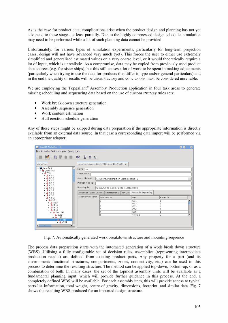
Fig. 7: Automatically generated work breakdown structure and mounting sequence
The process data preparation starts with the automated generation of a work break down structure
(WBS). Utilising a fully configurable set of decision rules, assemblies (representing intermediate
production results) are defined from existing product parts. Any property for a part (and its
environment: functional structures, compartments, zones, connectivity, etc.) can be used in this
process to determine the resulting structure. The method can be applied top-down, bottom-up, or as a
combination of both. In many cases, the set of the topmost assembly units will be available as a
fundamental planning input, which will provide further guidance in this process. At the end, a
completely defined WBS will be available. For each assembly item, this will provide access to typical
parts list information, total weight, centre of gravity, dimensions, footprint, and similar data. Fig. 7
shows the resulting WBS produced for an imported design structure.

106
Additionally, production sequences like mounting sequences within assemblies are required. This
information is also often missing. Using a selectable strategy-based approach, the default assembly
sequence can be automatically proposed by the system. The strategy rules have access to part and
assembly information and can thus consider important factors like type of item, weight, mounting or
welding requirements, need for fitting work etc.
Work content data is an essential input for most simulation experiments. Pre-calculated work content
will be used for activities that are not further broken down into individual (sub-)activities are therefore
closely related to the level of detail to be applied. In other cases, work content will be evaluated
during the simulation, possibly taking into account actual conditions such as environmental
information or introducing stochastic behaviour.
Fig. 8: Generated hull erection schedule based on WBS and work content
Again, the main issue here is early availability and sufficient accuracy of such data. Using the
fabrication method approach mentioned before, it is possible to estimate work content precisely based
on product properties and production method used, either as deterministic static values before or
dynamic, possibly stochastic values during simulation.
The final step consists of defining the hull erection schedule. Fig. 8 shows a grand block structure and
the assembly erection sequence derived from it. The actual conditions for stacking or attaching blocks
are fully configurable and can be made to consider the function and other properties of the
intermediate grand block product. The sequence also provides target milestone dates for preceding
production levels based on the estimated work content. The result can be used as a “skeleton” target
schedule to drive simulations, e.g. by issuing the corresponding work orders.
107
8. Configuring and Running Simulation Cases
A simulation scenario is considered to be the high level configuration for a simulation task. It involves
selecting all the data stores to be considered. In our simulation modelling environment, a scenario
effectively acts like an inventory of all model items that may play a role in the simulation. The
detailed configuration occurs on the simulation case level. This includes selecting /deselecting
individual items or assigning life cycle information to those items (for example, if some machine shall
be phased in at some point in time).
Simulation can only be initiated with some stimulus data. For production type simulations e.g. a set of
work orders related to manufacture of products (at any level) or delivery events for material deliveries
may be used. During case configuration, a variety of stimuli generators can be selected and
configured.
Finally, some fundamental execution parameters will be set, e.g. calendar time, start and stop time,
deadlock detection rules, etc.
The simulation runtime architecture includes a number of “administrational” entities representing
planning and decision-making tasks. Jobs need to be scheduled, transports need to be organized,
material is being requested, and process execution must be monitored. The chosen architecture
reflects the necessary administrational structures. All these planning and decision-making tasks
however are built on some sort of strategy. For example, choosing the next available work place for
some task could be performed on one extreme as a pure random selection among the available items
or it could on the other end be done in an entirely deterministic way. Between those extremes a
number of other mechanisms might be applicable. This requirement is addressed by providing
different strategies as pluggable modules that can be selected at model configuration time. Strategies
can reflect anything from the classical theoretical concepts like first-come/first-served, last-in/first-out
for handling of queuing problems, or random assignments using distributions to dispatching based on
using weighted preferences and/or decision rules.
To configure the strategies, the desired strategy type is selected for the target controller function.
Depending on the strategy chosen, a corresponding selection of configurable parameters can be
adjusted according to the individual needs.
Pluggable strategies offer a lot of features for experimentation. When working with technically
innovative products, it is often somewhat unclear whether traditional approaches will work as
expected. Running various simulations based on different or modified strategies will provide a lot of
what-if analysis capabilities.
Executing a single simulation is only one single step in searching for a solution of a problem. Under
normal conditions, analysis of results will lead to a modification of some input parameters to create a
new experiment. This can typically result in a large number of different runs, some of which may only
differ by small details while other runs will reflect substantial modifications e.g. of the production
facilities, resource constraints, scheduling, etc. In order to help users manage the variety of
possibilities, hierarchical experiment storage is being used. By grouping runs into scenarios,
experiments, and multiple levels of cases, some organizational guidance is provided. For every case,
references to all input data, configuration data, and output data are persistently stored. Any input
configuration can be visualized again and re-run or be used as the starting point for another variation.
Any output data set can be re-analysed again and used for comparative studies.
9. Conclusions and possible future directions
Our recent work and experience gained with simulation projects has led to the development of a real-
world modelling environment for one-of-a-kind production applications. By enabling users to work
with representations of concrete objects, the requirement modelling effort has become quite

108
manageable. However, when it comes to new types of products or long-term projects of products not
yet designed in detail, the automated generation of input data becomes the real challenge. The
approach chosen for our solution seems to be very promising in this respect.
For future work, we see a number of interesting directions. For example, advanced support methods
for the definition of templates for virtual products will further expand this capability. Or, massively
parallelising simulation execution will further progress with the goal to enable users to investigate
much broader variations of cases. This of course will make optimisation tasks more practical even for
day to day operations.
References
AES (2009), Topgallant® Adapter Development Kit, Documentation, Rev. 1.5, Atlantec Enterprise
Solutions, http://www.atlantec-es.com/.
FUJIMOTO, R. (2000): Parallel and Distributed Simulation Systems. Wiley-Interscience Publication.
HILDEBRANDT, S.; KOCH, T. (2005), Integrated Information Management and Computer Aided
Production Planning, COMPIT ‘05, Hamburg, pp.37-48.
KREUTZER, W. (1986), System simulation: programming styles and languages, Addison Wesley.
LSMS (2010), Large Scale Computer Simulation Modeling System for Shipbuilding, NRSP Report, http://www.nsrp.org/Project_Information/major_projects/deliverables/ase_801004.pdf
PIDD, M. (2004), Computer simulation in management science, 5th ed., John Wiley & Sons.
STEINHAUER, D. (2005), SAPP – Simulation Aided Production Planning at Flensburger,
COMPIT ’05, Hamburg, pp.391-398.
STEINHAUER, D. (2010), GeneSim – Development of a Generic Data Model for Production
Simulation in Shipbuilding, COMPIT ’10, Gubbio, pp.304-310.
WANNER, M.-C.; BOHNENBERG, R.; KOTHE, U.; SENDER, J.; CZARNIETZKI, R. (2010),
Development of a Methodology for Calculating Production Times based on Parameters,
COMPIT ’10, Gubbio, pp.449-457.


