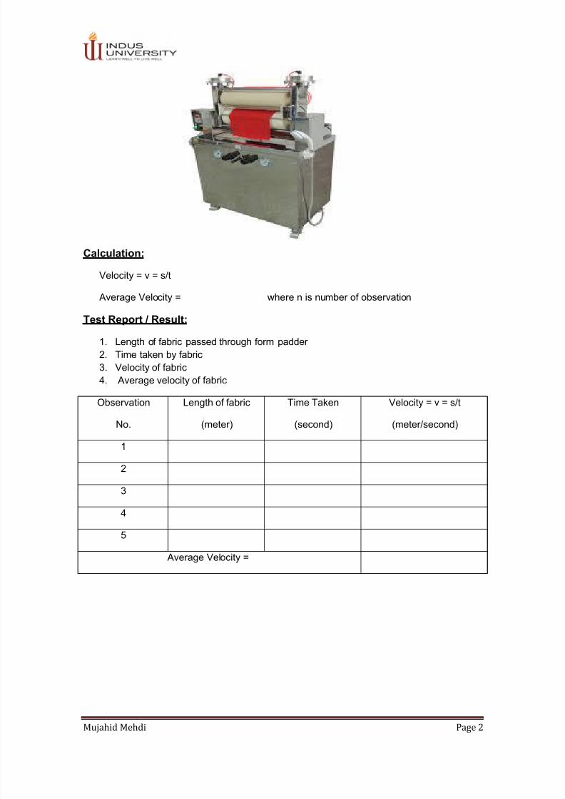
+ All Categories
Home > Documents > Complete Textile Mechanics Lab

Complete Textile Mechanics Lab

Date post: 13-Apr-2018
Category:
Upload: engr-mujahid-mehdi
View: 232 times
Download: 0 times
Share this document with a friend
48
 1 LAB E XPER IME NT 01 Linear Velocity To determine the linear velocity of f abric running through the padder PERFORMANCE/OBJECTIVES Upon successful completion of this experiment, the student will be able to, i. Understand the basic concept, of measurement of linear velocity of fabric in a processing machine. ii. Operate laboratory padding machine. iii. Be aware of the working principle of a padder. Tools/ Apparatus: Laboratory Padder, Piece of woven fabric of specified length and stopwatch Theory: Velocity may be defined as the distance covered per unit time in a particular direction. Mathematically, V = s / t …..(1.1) Where s is the displacement and t  represent time Procedure: 1. Take a piece of fabric of spe cified Length 2. Switch on the padding machine. 3. Set appropria te pressure of squeezing rollers. 4. Feed one e nd of the fabric to the nip of squ eezing rol lers. 5. Switch on the stopwatch, as fabric sta rt moving th rough nip of the roll ers. 6. Switch off the stopwatch as soon as s econd end of the fabric comes out from nip of the rollers. 7. Note the time taken by th e fabric to pass through the squeezing rollers. 8. Repeat the same for five times and the time each time. 9. Calculate the velocity b y putting the values o f length o f fabric and time in eq. 1.1. 10. Calculate the average velocity from five readings. Student Name: _____________ ID No. ___ Signature of the lab tutor ___________________ Date: ________________ _____
Transcript

7/24/2019 Complete Textile Mechanics Lab

http://slidepdf.com/reader/full/complete-textile-mechanics-lab 1/47


1

LAB EXPERIMENT 01 Linear Velocity 

To determine the linear velocity of fabric running through the

padder

PERFORMANCE/OBJECTIVES

Upon successful completion of this experiment, the student will be able to,

i. Understand the basic concept, of measurement of linear velocity of fabric in a

processing machine.

ii. Operate laboratory padding machine.

iii. Be aware of the working principle of a padder.

Tools/ Apparatus:

Laboratory Padder, Piece of woven fabric of specified length and stopwatch

Theory:

Velocity may be defined as the distance covered per unit time in a particular direction.

Mathematically,

V = s / t …..(1.1) 

Where s is the displacement and t  represent time

Procedure:

1. Take a piece of fabric of specified Length

2. Switch on the padding machine.3. Set appropriate pressure of squeezing rollers.

4. Feed one end of the fabric to the nip of squeezing rollers.

5. Switch on the stopwatch, as fabric start moving through nip of the rollers.

6. Switch off the stopwatch as soon as second end of the fabric comes out from nip of

the rollers.

7. Note the time taken by the fabric to pass through the squeezing rollers.

8. Repeat the same for five times and the time each time.

9. Calculate the velocity by putting the values of length of fabric and time in eq. 1.1.

10. Calculate the average velocity from five readings.

Student Name: _______________________________ ID No. ____________________

Signature of the lab tutor ___________________ Date: _____________________

7/24/2019 Complete Textile Mechanics Lab

http://slidepdf.com/reader/full/complete-textile-mechanics-lab 2/47


Mujahid Mehdi Page 2

Calculation:

Velocity = v = s/t

 Average Velocity = where n is number of observation

Test Report / Result:

1. Length of fabric passed through form padder

2. Time taken by fabric

3. Velocity of fabric

4. Average velocity of fabric

Observation

No.

Length of fabric

(meter)

Time Taken

(second)

Velocity = v = s/t

(meter/second) 

1

2

3

4

5

 Average Velocity =

7/24/2019 Complete Textile Mechanics Lab

http://slidepdf.com/reader/full/complete-textile-mechanics-lab 3/47


Mujahid Mehdi Page 3

TEST RESULT / OBSERVATIONS:

 _________________________________________________________________________ 

 _________________________________________________________________________ 

 ________________________________________________________________________

Review Question:

1. What is the function of squeezing rollers?

 ______________________________________________________________________ 

 ______________________________________________________________________ 

 ______________________________________________________________________

2. Calculate the diameter of squeezing rollers. (Hint! Surface speed = π × Diameter × rotaryspeed); Find data from practical done?

 ______________________________________________________________________ 

 ______________________________________________________________________ 

 ______________________________________________________________________

Final Checklist:

1. Clean your apparatus and workbench before you leave.

2. Keep the apparatus back to their proper places.

3. Submit your answer to questions and result before the next laboratory experiment

according to the time table.

7/24/2019 Complete Textile Mechanics Lab

http://slidepdf.com/reader/full/complete-textile-mechanics-lab 4/47


Mujahid Mehdi Page 4

LAB EXPERIMENT 02 ROTARY SPEED AND TACHOMETRE 

To determine the rotary speed of revolving components of textilemachines by employing tachometer (speed of loom)

Performance objectives:

Upon this experiment competition the student will be able to:

1-understand the concept of rotary speed2- Measure the speed of loom and other rotary components

3- Know the working principle and use of tachometer

Apparatus:

Tachometer, loom or any textile machine those specific locations where tachometer can beused.

Theory:

Circular motion is a simple type of motion in which the objects move in a circular path , if anobject has constant speed but acceleration always at right angle to its velocity ,it will travel ina circle .The easiest example id that of a stone on a string ,in steady state conditions ,thespeed of movement of the stone is constant ,but the direction is constant changing so we areunable to assign the directional component to its motion .in this case circular displacement isconsidered in term of angle subtended at center of the circle by the arc representing the pathof displacement. If the stone is moving on constant speed and at a fixed radius turns in agiven time must be constant .at high speed this angle can be measure as the number ofrevolutions taking place in the time interval instead of expressing it as an angle.

There are two types of instruments, Tachometer and stroboscope, which are commonlyused to measure type rotating speed of rotating machine parts.

Tachometer is a measuring device that indicates rotational speed in revolutions per minutes,the tachometer may be mechanical or electronically.

Procedure:

1- Switch the loom and run it.

2- Take the tachometer with range of higher of the speed of loom

3- Put the shaft of tachometer on the specific location of main shaft of the loom with the

help of appropriate touching tool.

4- Note the readings on tachometer

5- Repeat the same for five times and note the readings

6- Calculate the average rotary speed of the loom (or a rotating part of the machine).

Student Name: ____________________________________ ID No. ____________________

Signature of the lab tutor________________________ Date: _____________________

7/24/2019 Complete Textile Mechanics Lab

http://slidepdf.com/reader/full/complete-textile-mechanics-lab 5/47


Mujahid Mehdi Page 5

Calculation:

 Average rotary speed = N =∑N/n,

Where n is the number of observations. 

Test report / Results:

1-Individual readings of speed taken by tachometer in Rev/min2-Average speed

Observation Readings of the tachometer=N(rpm)

1

2

3

4

5

Average Velocity = N rpm = _______________

TEST RESULT / OBSERVATIONS:

 _________________________________________________________________________ 

 _________________________________________________________________________ 

 ________________________________________________________________________

7/24/2019 Complete Textile Mechanics Lab

http://slidepdf.com/reader/full/complete-textile-mechanics-lab 6/47


Mujahid Mehdi Page 6

Review Questions:

1. What do mean by loom?

 ______________________________________________________________________ 

 ______________________________________________________________________ 

 _____________________________________________________________________

2. Calculate the angular speed of loom shaft in rad/s?

 ______________________________________________________________________ 

 ______________________________________________________________________ 

 _____________________________________________________________________

3. Explain briefly working principle of tachometer?

 ______________________________________________________________________ 

 ______________________________________________________________________ 

 _____________________________________________________________________

Final checklist:

1- Clean your apparatus and work bench before you leave. 

2- Keep the apparatus to their proper place. 

3- Submit your answer to questions and results before the next laboratory experiments

according to the time table. 

7/24/2019 Complete Textile Mechanics Lab

http://slidepdf.com/reader/full/complete-textile-mechanics-lab 7/47


Mujahid Mehdi Page 7

LAB EXPERIMENT 03 Rotary Speed & Strobo sco pe

To Determine the Speed of Revolving Components of Textile

Machines by Using Stroboscope (Speed of a Traveler on Ring

Frame)

PERFORMANCE/OBJECTIVES

Upon successful completion of this experiment, the student will be able to:

  Understand the concept of rotatory speed

  Measure speed of traveler on ring frame and other rotating components of textile

machines by using stroboscope.

  Know the working principle and use of stroboscope.

TOOLS:

Stroboscope, Ring frame (or any other textile machine containing rotatory parts).

THEORY:

Stroboscope is a device used to measure the rotary and oscillating speeds by makingrevolving or oscillating object appears to be at rest. It is widely used to measure the rotary

part of the machine. The principle of stroboscope is based on the frequency of flashing light.

The machine component seems stationary when the frequency of flashing light is equal to

the speed of the machine component, which is to be observed.

The operation of the stroboscope is worthy of a slight digression. It depends on the

phenomenon of persistence of vision in the human eye and operates by illuminating, for a

very brief period of time the machinery under inspection at a precisely repeated time interval

of extremely short duration. This time interval may be varied by adjustment of the

stroboscope controls, so that a series of rapid flashes of light, each lasting perhaps a

milliseconds or less, is directed at the moving machinery. If a particular point on the moving

machine happens to be in precisely the same position at each time an illuminating flashes

reaches it, the human eye and brain interpret this coincidence by assuming that the point

has not moved between successive flashes. As a result, a stationary image of point, and

hence of the entire piece of the mechanism of which it is a part, is seen under the

illumination. Practical operation of the instrument merely consists in adjusting the

stroboscope controls until the part being examined appears stationary, this being followed by

a reading of its vehicle on the calibrated scale of of the device.

Student Name: _______________________________ ID No. ____________________

Signature of the lab tutor ___________________ Date: _____________________

7/24/2019 Complete Textile Mechanics Lab

http://slidepdf.com/reader/full/complete-textile-mechanics-lab 8/47


Mujahid Mehdi Page 8

PROCEDURE:

1. Switch the ring frame and start manufacturing of yarn (or any other textile machine).

2. Switch on the stroboscope.

3. Put the flash light of stroboscope on the rotating traveler (or rotating part of machine).

4. Vary the frequency of the flash until the rotating part seems still.

5. Note the rate of flashes on the display of stroboscope and that is the speed of

rotating pat in rpm.

6. Repeat the same for the 5 times and note the reading.

7. Calculate the average speed.

CALCULATION 

 Average rotatory speed = N = ∑N/n, where „n‟ is number of observations 

EXPERIMENT RESULTS / OBSERVATIONS 

  Individual reading of speed taken by stroboscope in revolution/minute.

  Average speed

Observat ion Numb er Reading on strob osc ope = N (RPM)

1

2

3

4

5

Av erage Veloci ty = N rpm

7/24/2019 Complete Textile Mechanics Lab

http://slidepdf.com/reader/full/complete-textile-mechanics-lab 9/47


Mujahid Mehdi Page 9

OBSERVATIONS:

 _________________________________________________________________________ 

 _________________________________________________________________________ 

 _________________________________________________________________________

REVIEW QUESTIONS 

1. What is the function of flash light in the stroboscope?

 ___________________________________________________________________ 

 ___________________________________________________________________ 

 ___________________________________________________________________

2. What is the difference between stroboscope and tachometer?

 ___________________________________________________________________ 

 ___________________________________________________________________ 

 ___________________________________________________________________

3. Calculate the angular speed of traveler in rad/s? (Hint! Angular speed in rad/s = N in

rpm x (2π/60); Find data from practical done) 

 ___________________________________________________________________ 

 ___________________________________________________________________ 

 ___________________________________________________________________

Final checkl ist  

  Clean your apparatus and work bench before you leave.

  Keep the apparatus back to their proper places.

  Submit your answers to questions and results before the next laboratory experiment

according to the time table.

7/24/2019 Complete Textile Mechanics Lab

http://slidepdf.com/reader/full/complete-textile-mechanics-lab 10/47


Mujahid Mehdi Page 10

LAB EXPERIMENT 04 

Verification of law of conservation of Energy

Performance objectives:

Upon this experiment competition the student will be able to:

1- Understand the law of conservation of energy2- Have the clear concept of potential energy ,kinetic energy and total energy

Apparatus:

Thread, Scale, Metallic Bob of known mass

Theory:

Energy is defined is capacity of doing work ,it may exist in many forms , such as potential

,kinetic thermal pressure strain electromagnetically and the chemical energy , energy may

be stored the methods of storing the energy involved , potential energy , the form which

depends on the position of the body above the datum reference level. Is stored by retaining

the body in that position. its value depends on the weight of the body and its height abovethe reference level and equal to the product of the two. This value is also equal to the work

done in elevating the body to its position from the reference level, and this amount of energy

is stored as long as body by virtue of its motion, its obviously not stored.

The principle of conservation of energy states that energy can neither be created nor be

destroyed although it may be transformed from one form to another; this also means that the

total energy of the system remains constant.

When the bob s lifted upon up to A it gain the potential energy equal to the mass X

acceleration due to the gravity X height lifted to

P.E = mgh

If the body is dropped towards the P ,its potential energy is gradually converted into kinetic

energy as it falls until just before impact with the ground all the potential energy has been

converted to the kinetic energy.

K.E. ½ mv2

Therefore, ½ mv2 = mgh

It is possible to calculate t

Student Name: ____________________________________ ID No. ____________________

Signature of the lab tutor________________________ Date: _____________________

7/24/2019 Complete Textile Mechanics Lab

http://slidepdf.com/reader/full/complete-textile-mechanics-lab 11/47


Mujahid Mehdi Page 11

 According to the law of the conservation of energy,

Total energy at position A =total energy at point B = total energy at position P

Procedure:

1- Hang the metallic bob on a hook with the help of piece of thread as in Fig 4.1  

2- Measure the height from the center of the bob to the thread attached with hook

3- Raise the bob up to the level of hook where thread is fixed 

4- Specify three positions during the motion of bob

5- Calculate total energy at position A, B where the potential energy is at maximum and

potential energy is at zero at position. A and B and kinetic energy is maximum and

potential energy is zero at position P. Calculate v from the equation 4.3.  

Calculation:

 At position A and B:

Total energy (T.E) = P.E + K.E

= P.E

= mgh

 At position P:

Total energy (T.E) = P.E + K.E

=K.E = ½ mv2

Total energy at position A Total energy at position B Total energy at position P

The total energy of the system is ___________ and is equal to the all positions.

7/24/2019 Complete Textile Mechanics Lab

http://slidepdf.com/reader/full/complete-textile-mechanics-lab 12/47


Mujahid Mehdi Page 12

OBSERVATIONS:

 _________________________________________________________________________ 

 _________________________________________________________________________ 

 _________________________________________________________________________  

Review Questions:

1- What do you understand by impact velocity?

 ___________________________________________________________________ 

 ___________________________________________________________________ 

 ___________________________________________________________________

2- Briefly explain, why can the kinetic energy not be stored?

 ___________________________________________________________________ 

 ___________________________________________________________________ 

 ___________________________________________________________________

Final checklist:

4- Clean your apparatus and work bench before you leave. 

5- Keep the apparatus to their proper place. 

6- Submit your answer to questions and results before the next laboratory experiments

according to the time table. 

7/24/2019 Complete Textile Mechanics Lab

http://slidepdf.com/reader/full/complete-textile-mechanics-lab 13/47


Mujahid Mehdi Page 13

LAB EXPERIMENT 05

To Determine the Co-efficient of Static Friction of a Fabric on a

Horizontal Stainless Steel Plane 

Performance Objective

Upon successful completion of this experiment the student will be able to:

i) Understand what is friction and its behavior.ii) Measure co-efficient of friction on a horizontal plane.iii) Have clear concept of the static friction between two contacting surfaces.

Apparatus

Horizontal Stainless Steel Surface with a frictionless pulley, Wooden Block, Piece of string,

Fabric to be tested, Weighing Pan and Weight Box.

Discussion / Theory

The friction is the force that opposes the motion or tendency of motion of an object when the

object is an contact with another object or surface. Friction is essential for various holding

and fastening devices as well as for friction drives and brakes and even for supplying the

traction for walking or driving automobiles. It has some disadvantages also; it causes lose of

power and / or wear.

Student Name: _____________________________________ ID No. ____________________

Signature of the lab tutor: ________________________ Date: _____________________

7/24/2019 Complete Textile Mechanics Lab

http://slidepdf.com/reader/full/complete-textile-mechanics-lab 14/47


Mujahid Mehdi Page 14

The magnitude of the frictional force F is directly proportional to the magnitude of the

resultant normal force N. The resultant normal force is a contacting force because of which

to surface are in contact. When the contact of two surface is horizontal, the magnitude of the

normal force is equal to the weight of upper body. Fig 5.1 illustrates the contact of two

surface horizontally.

F ~ N

Or F = µ N  

Where µ = Co-efficient of fric tion

The co-efficient of static friction between two stationary surfaces is defined as the ratio of

limiting frictional force of resistance opposing their relative motion to the force, measured

perpendicular to the common point or plane of contact, pressing the two together:

µ = F / N

Procedure / Method

1. Cover the wooden block with the fabric on be tested in such a way that the surface of

fabric must be free from crease and weigh it. The magnitude of its weight is equal to

the magnitude of normal force N. 

2. Place the wooden block on the horizontal stainless steel surface attach the string on

one side of wooden block, pass it over pulley and attach a weighing pan on the other end

of the other end of the string as show in Fig.5.2.

3. Now place some weight on the weighing pan.

4. After placing some weight check friction of fabric surface on the horizontal stainless

steel surface by taping.

5. If wooden block moves by taping then note the magnitude of force exerted by total

weight of weighing pan ( i.e. the magnitude of limiting frictional force F) and the

magnitude of resultant normal force N ( i.e the magnitude of total weight exerted on

stainless steel surface by wooden block).

6. Calculate the co-efficient of static friction by using equation 5.1.

7. Repeat above procedure five times by increasing the weight of wooden block.

8. Calculate the average co-efficient of static friction.

7/24/2019 Complete Textile Mechanics Lab

http://slidepdf.com/reader/full/complete-textile-mechanics-lab 15/47


Mujahid Mehdi Page 15

Calculation

Co-efficient of static friction = µ = F / N

 Average µ =Σµ/n, where n is number of observations 

Test Report / Result

1. Fabric Specifications

2. Resultant Normal Force.

3. Frictional Force. 

4. Co-efficient of static friction. 

5. Average Co-efficient of friction. 

Fabric Specification

i) Material (Fiber)

ii) Construction

iii) Condition (Grey / Treated / Dyed / Printed / Finished)

If finished, specify type of finish.

TEST RESULT / OBSERVATIONS:

 _________________________________________________________________________ 

 _________________________________________________________________________ 

 _________________________________________________________________________  

Observation No. Normal Force = N

(Newton‟s) Frictional Force = F

(Newton‟s) Co-efficient of static friction =

F/N

1

2

3

4

5

Average µ → 

7/24/2019 Complete Textile Mechanics Lab

http://slidepdf.com/reader/full/complete-textile-mechanics-lab 16/47


Mujahid Mehdi Page 16

Review Questions

1. What do understand by static friction and kinetic friction?

 ___________________________________________________________________ 

 ___________________________________________________________________ 

 ___________________________________________________________________

2. What is the influence of Physical properties of contacting on co-efficient of friction?

 ___________________________________________________________________ 

 ___________________________________________________________________ 

 ___________________________________________________________________

3. What is the effect of fabric construction and material on its co-efficient of friction?

 ___________________________________________________________________ 

 ___________________________________________________________________ 

 ___________________________________________________________________

4. Why taping is done to initiate motion of the block when pulley is used

 ___________________________________________________________________ 

 ___________________________________________________________________ 

 ___________________________________________________________________

Final Checklist

1. Clean your apparatus and workbench before you leave.

2. Keep the apparatus back to their proper places.

3. Submit your answers to questions and results before the next laboratory experiment

according to the time table.

7/24/2019 Complete Textile Mechanics Lab

http://slidepdf.com/reader/full/complete-textile-mechanics-lab 17/47


Mujahid Mehdi Page 17

LAB EXPERIMENT 06

To determine the co-efficient of static friction of a fabric on an

inclined stainless steel plane

Performance object:

Upon successful completion of this experiment, the student will be able to:

i) Understand what is friction and its behavior.

ii) Measure co-efficient of static friction on an inclined plane.

iii) Have clear concept of the static friction between two contacting surfaces.

Apparatus:

Inclined stainless steel surface with a frictionless pulley (attached to a wooden base).Wooden block, Piece of String, Fabric to be tested, Weighting pan and weighting Box.

Discussion/Theory:

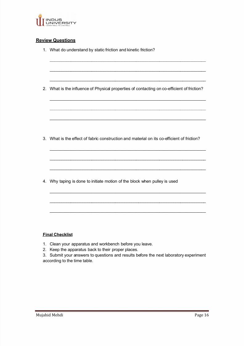
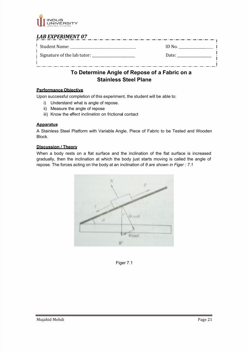
The friction is the force that opposes the motion or tendency of motion of an object when theobject is in contact with another object or surface. The magnitude of the frictional force F isdirectly proportional to the magnitude of the resultant normal force N. The resultant normalforce is a contacting force because of which two surfaces in contact. When the contact oftwo surfaces is horizontal, the magnitude of the normal force is equal to the weight of upperbody. Figure 6.1 illustrates the contact of two surfaces at certain angle(or at an inclination,Ɵ) 

F ∞ N  

Or

F= µ N

Figure 6.1

From Figure 6.1, we get

N= W cos Ɵ 

F= P-W sin Ɵ 

Student Name: ____________________________________ ID No. ____________________

Signature of the lab tutor________________________ Date: _____________________

7/24/2019 Complete Textile Mechanics Lab

http://slidepdf.com/reader/full/complete-textile-mechanics-lab 18/47


Mujahid Mehdi Page 18

Therefore equation 6.1 is modified as,

µ= P-W sin Ɵ (6.2)

W cos Ɵ 

Where

µ= Co-efficient of friction P= Load on string W= Weight of the blockƟ= Angle of the inclined plane with horizontal=inclinationF= Resultant frictional force

Procedure/Method:

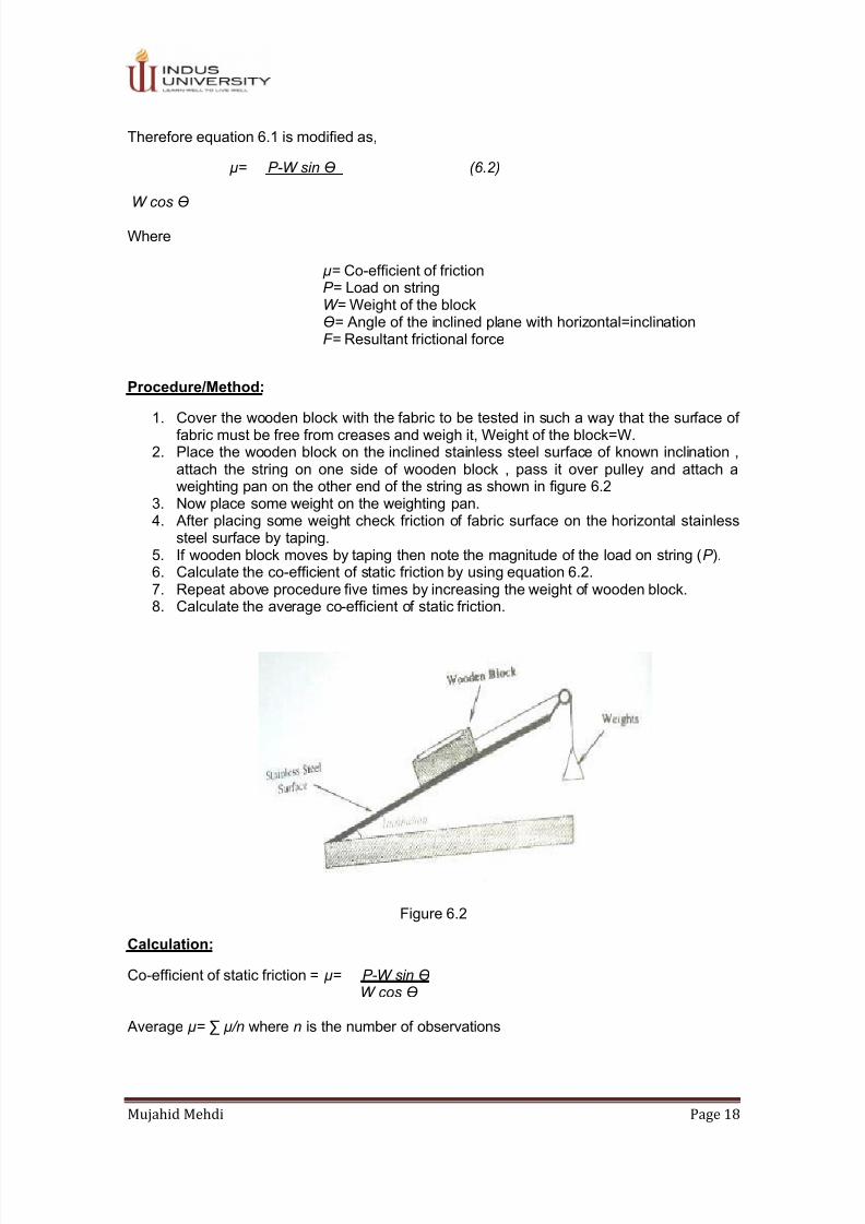
1. Cover the wooden block with the fabric to be tested in such a way that the surface offabric must be free from creases and weigh it, Weight of the block=W.

2. Place the wooden block on the inclined stainless steel surface of known inclination ,attach the string on one side of wooden block , pass it over pulley and attach aweighting pan on the other end of the string as shown in figure 6.2

3. Now place some weight on the weighting pan.4. After placing some weight check friction of fabric surface on the horizontal stainless

steel surface by taping.5. If wooden block moves by taping then note the magnitude of the load on string (P ).6. Calculate the co-efficient of static friction by using equation 6.2.7. Repeat above procedure five times by increasing the weight of wooden block.

8. Calculate the average co-efficient of static friction.

Figure 6.2

Calculation:

Co-efficient of static friction = µ= P-W sin ƟW cos Ɵ 

 Average µ= ∑ µ/n where n is the number of observations

7/24/2019 Complete Textile Mechanics Lab

http://slidepdf.com/reader/full/complete-textile-mechanics-lab 19/47


Mujahid Mehdi Page 19

Test Report / Results:

1. Fabric Specifications.

2. Inclination.

3. Total weight of wooden block.

4. Total load on string.

5. Co-efficient of static friction (µ).

6. Average Co-efficient of static friction.

Fabric Specif icat ion :

(i) Material (fiber)

(ii) Construction

(iii) Condition (Grey/Treated/Dyed/Printed/Finished) if finished, specify type of finish

Observation

No.

Inclination= Ɵ  

(radians/Degrees)

Weight of Block

= W (newton’s) 

Load on string

=P (newton’s) 

µ= P- W sin Ɵ

W cos Ɵ  

1

2

3

4

5

Average µ

OBSERVATIONS:

 _________________________________________________________________________ 

 _________________________________________________________________________ 

 _________________________________________________________________________

7/24/2019 Complete Textile Mechanics Lab

http://slidepdf.com/reader/full/complete-textile-mechanics-lab 20/47


Mujahid Mehdi Page 20

Review Questions:

1. What is the difference between horizontal and inclined plane?

 ___________________________________________________________________ 

 ___________________________________________________________________ 

 __________________________________________________________________

2. What is the effect of inclination on Co-efficient of friction?

 ___________________________________________________________________ 

 ___________________________________________________________________ 

 __________________________________________________________________

3. Write the application of friction in the field of textile?

 ___________________________________________________________________ 

 ___________________________________________________________________ 

 __________________________________________________________________

Final Checklist:

1. Clean your apparatus and workbench before you leave.

2. Keep the apparatus back to their proper places.

3. Submit your answers to questions and results before the next laboratory experiment

according to the time table.

7/24/2019 Complete Textile Mechanics Lab

http://slidepdf.com/reader/full/complete-textile-mechanics-lab 21/47


Mujahid Mehdi Page 21

LAB EXPERIMENT 07  

To Determine Angle of Repose of a Fabric on a

Stainless Steel Plane

Performance Objective 

Upon successful completion of this experiment, the student will be able to:

i) Understand what is angle of repose.

ii) Measure the angle of repose

iii) Know the effect inclination on frictional contact

Apparatus 

 A Stainless Steel Platform with Variable Angle, Piece of Fabric to be Tested and Wooden

Block.

Discussion / Theory 

When a body rests on a flat surface and the inclination of the flat surface is increased

gradually, then the inclination at which the body just starts moving is called the angle of

repose. The forces acting on the body at an inclination of θ are shown in Figer : 7.1 

Figer 7.1

Student Name: ______________________________________ ID No. ____________________ 

Signature of the lab tutor: _________________________ Date: ____________________ 

7/24/2019 Complete Textile Mechanics Lab

http://slidepdf.com/reader/full/complete-textile-mechanics-lab 22/47


Mujahid Mehdi Page 22

F  is the frictional force and its magnitude is given as,

F = W sinθ  

N   is the normal force and its magnitude is given as,

N = W cosθ  

 As we know that co-efficient of friction is given by,

µ = F / N

Therefore, in this case, the co-efficient is given by,

µ = W sinθ / W cosθ  

or µ =  , where = tanθ  

Hence, µ = tanθ   …(7.1)

Procedure / Method 

1. Cover the wooden block with the fabric to be tested in such a way that the surface of

fabric must be free creases and weight it. Weight of the block = W .

2. Place the wooden block on the stainless surface.

3. Now increase the inclination of steel platform slowly.

4. Keep increasing the inclination till block starts moving.

5. Note the angle / inclination (θ) at which the block starts moving.

6. Repeat the procedure five times and note the inclination each time.

7. Calculate the average value of the angle.

8. Calculate the co-efficient of friction from the value of average inclination.

Calculation 

 Angle of Repose = θ  

 Average θ = Ʃ θ/n, where n is number of observations 

Normal Force = N  = W cos θ  

Frictional Force = F  = W sin θ  

Co-efficient of friction = µ = tan θ  

Test Result / Report 

1. Fabric Specifications

2. Angle of Repose

3. Average Angle of Repose

4. Weight of the Block

5. Frictional Force

6. Normal Force7. Co-efficient of Friction

7/24/2019 Complete Textile Mechanics Lab

http://slidepdf.com/reader/full/complete-textile-mechanics-lab 23/47


Mujahid Mehdi Page 23

Fabric Specification:

i) Material (Fabric)

ii) Construction

iii) Condition (Grey / Treated / Dyed / Printed / Finished)

If finished, specify type of finish.

Observation

No.

 Angle of Repose = θ  

(radian / degree)

 Average Angle of

Repose

(radian / degree)

1.

2.

3.

4.

5.

Weight of the Block

W = mg (newton)

Frictional Force

F = W sinθ (newton) 

Normal Force

N = W cosθ (newton) 

Co-efficient of

Friction

µ = tanθ  

OBSERVATIONS:

 _________________________________________________________________________ 

 _________________________________________________________________________ 

 _________________________________________________________________________  

7/24/2019 Complete Textile Mechanics Lab

http://slidepdf.com/reader/full/complete-textile-mechanics-lab 24/47


Mujahid Mehdi Page 24

Review Question 

1. Discuss the effect of inclination on co-efficient of friction?

 ___________________________________________________________________ 

 ___________________________________________________________________ 

 ___________________________________________________________________ 

 ________

2. If the angle of repose of a body is 1”, then briefly discuss about its friction? 

 ___________________________________________________________________ 

 ___________________________________________________________________ 

 ___________________________________________________________________ 

 ________

Final Checklist:

1. Clean your apparatus and workbench before you leave.

2. Keep the apparatus back to their proper places.

3. Submit your answer to questions and result before the next laboratory experiment

according to the time table.

7/24/2019 Complete Textile Mechanics Lab

http://slidepdf.com/reader/full/complete-textile-mechanics-lab 25/47


Mujahid Mehdi Page 25

LAB EXPERIMENT 08

To study the effect of increase length of simple pendulum on the

time period

Performance Objectives:

(i) To demonstrate the working principle of a simple pendulum.

(ii) To calculate the time period of a simple pendulum. 

Apparatus:

Metallic bob of varied diameter, stop watch, clamping stand, ruler, vernier caliper, and

thread.

Discussion / Theory:

 An ideal simple pendulum consists of a spherical bob suspended from a light, inextensible

string tied to a fixed, rigid and frictionless support. When the bob is displaced from its rest

position, it begins to perform oscillatory motion.

Distance between the points of suspension and the center of the bob is called the “Length ofPendulum”. Time taken to complete one vibration is called its “Time Period”.

Procedure / Method:

1. Find the diameter of the metallic bob with the help of vernier caliper in cm.2. Calculate the radius of metallic bob in cm.3. Tie one end of the thread to the hook of the bob and hold the other end in your end.

Let the ball hang freely.4. Using ruler, mark on the thread length of 30 cm, 35 cm, 40 cm and 50 cm with pen.5. Pass the other end of the thread to the split cork up to 30 cm mark and rigidly

clamped it between the split cork edges.6. Adjust the height of the clamp so that the bob must be one or two inches above the

ground level.7. Displace the bob from its rest position with small amplitude.8. Start the stopwatch and note down the time taken by the bob for 20 continuous

vibrations.9. Similarly taken more reading with length 35 cm, 40 cm, 45 cm and 50 cm.10. With “L” on the X – axis and y – axis, draw a graph.

Student Name: _____________________________________ ID No. ____________________

Signature of the lab tutor: _________________________ Date: _____________________

7/24/2019 Complete Textile Mechanics Lab

http://slidepdf.com/reader/full/complete-textile-mechanics-lab 26/47


Mujahid Mehdi Page 26

Test Result / Report:

The test result / report should include the following particulars:

1. Diameter of the bob:2. Radius of the bob:3. Amplitude:4. Mass of bob of the pendulum:

Observation Table 8.1

S.

No.

Length of

the thread

“L” in cm 

Total length

L’ = (L+ r)

cm

Time (t) for 20

vibrations in sec

Time period

T = t / 20

(sec)

L’ / T2 

1.

2.

3.

4.

5.

Note: Take at least three readings followed by its mean value for (t) in seconds per test.

Graph:

OBSERVATIONS:

 _________________________________________________________________________ 

 _________________________________________________________________________ 

 _________________________________________________________________________

7/24/2019 Complete Textile Mechanics Lab

http://slidepdf.com/reader/full/complete-textile-mechanics-lab 27/47


Mujahid Mehdi Page 27

Precautions:

1. Amplitude of vibration should be small.2. Bob should move along a horizontal line without spinning.3. Avoid slippage of thread through the cork.

Review Questions:

1. What is simple pendulum?

 ___________________________________________________________________ 

 ___________________________________________________________________ 

 ___________________________________________________________________

2. Give example of vibratory motion in the field of textile?

 ____________________________________________________________________ 

 ____________________________________________________________________ 

 ____________________________________________________________________

3. Define the term “Time Period” 

 _____________________________________________________________________ 

 _____________________________________________________________________ 

 _____________________________________________________________________

Final Checklist

1. Clean your apparatus and workbench before you leave.2. Keep the apparatus back to their proper places.3. Submit your answers to questions together with your data calculations and results

before leaving the laboratory.

7/24/2019 Complete Textile Mechanics Lab

http://slidepdf.com/reader/full/complete-textile-mechanics-lab 28/47


Mujahid Mehdi Page 28

LAB EXPERIMENT 09 VALUE OF GRAVITY 

To Calculate the Value of “g” by the help of Simple Pendulum

PERFORMANCE/OBJECTIVES

(1) To learn how to calculate the value of “g” by simple pendulum (2) To understand the relationship between Length/ time period of simple pendulum

and their value of “g”. 

TOOLS

Metallic bob of varied diameters stop watch, Clamping, stand, ruler, vernier caliper and

thread.

THEORY

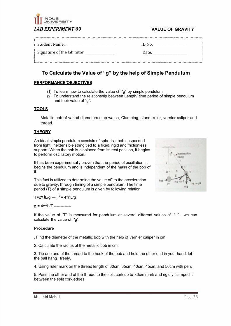
 An ideal simple pendulum consists of spherical bob suspendedfrom light, inextensible string tied to a fixed, rigid and frictionlesssupport. When the bob is displaced from its rest position, it beginsto perform oscillatory motion.

It has been experimentally proven that the period of oscillation, itbegins the pendulum and is independent of the mass of the bob ofit. 

This fact is utilized to determine the value of” to the accelerationdue to gravity, through timing of a simple pendulum. The timeperiod (T) of a simple pendulum is given by following relation

T=2  ∫L/g → T2= 4π2L /g

g = 4π2L /T -------------

If the value of “T” is measured for pendulum at several different values of “L” . we cancalculate the value of “g”. 

Procedure

. Find the diameter of the metallic bob with the help of vernier caliper in cm.

2. Calculate the radius of the metallic bob in cm.

3. Tie one and of the thread to the hook of the bob and hold the other end in your hand. letthe ball hang freely.

4. Using ruler mark on the thread length of 30cm, 35cm, 40cm, 45cm, and 50cm with pen.5. Pass the other and of the thread to the split cork up to 30cm mark and rigidly clamped itbetween the split cork edges.

Student Name: _______________________________ ID No. ____________________

Signature of the lab tutor ___________________ Date: _____________________

7/24/2019 Complete Textile Mechanics Lab

http://slidepdf.com/reader/full/complete-textile-mechanics-lab 29/47


Mujahid Mehdi Page 29

6. Adjust the height of the clamp so that the bob must be one or two inch above the groundlevel.

7. Displace the bob from its rest position with the small amplitude.

8. Start the stop watch and note down the time taken by the bob for 20 continues vibrations.

9. Similarly take more readings with lence 35cm ,40cm, 45cm, and 50cm.

10. Calculate the value of "G" by substituting the value of "L" and "T" in equation 7.1.

EXPERIMENT RESULTS / OBSERVATIONS 

The test result/Report should include the following particulars.

1. Diameter of the bob

2. Radius of the bob

3. Amplitude

4. Mass of the bob of the pendulum

S.Nos:

Length of the

thread "L" cm

Total length

L=(l+r) cm

Time (T) for

20 vibrations

in sec

Time period

T=t/20(sec)

1.

2.

3.

4.

5.

Observation:

 _________________________________________________________________________ 

 _________________________________________________________________________ 

 _________________________________________________________________________

Precaution:

1. Amplitude of vibration should be small.

2. Bob should move along a horizontal line without spinning.

3. Avoid slippage of thread through the cork.

7/24/2019 Complete Textile Mechanics Lab

http://slidepdf.com/reader/full/complete-textile-mechanics-lab 30/47


Mujahid Mehdi Page 30

Review Question: 

1. Discuss acceleration due to gravity?

 ___________________________________________________________________ 

 ___________________________________________________________________ 

 ___________________________________________________________________

2. Write down the regarding forces acting on simple pendulum during oscillation?

 ___________________________________________________________________ 

 ___________________________________________________________________ 

 ___________________________________________________________________

3. Define the term "Angular SHM"?

 ___________________________________________________________________ 

 ___________________________________________________________________ 

 ___________________________________________________________________

Final check List:

1. Clean your apparatus and work bench before you leave.

2. Keep the apparatus back to their proper place.

3. Submit your answers to question together with your data, calculation and result before

leaving the laboratory.

7/24/2019 Complete Textile Mechanics Lab

http://slidepdf.com/reader/full/complete-textile-mechanics-lab 31/47


Mujahid Mehdi Page 31

LAB EXPERIMENT 10

To demonstrate the working principle of Geneva mechanism on a

laboratory scale apparatus

Performance Objectives:

iv. To understand the work principle of Geneva mechanism.

v. To learn the importance in textile Engineering.

vi. To identify the factors affecting the performance of Geneva mechanism.

Apparatus:

Laboratory scale designed of Geneva mechanism.

Discussion / Theory :

The Geneva mechanism was originally invented by a watch maker. The name

derives from the devices eerier application in mechanical watches Switzerland and Geneva

being an important concern of watch making. It is also known as pin and star wheel. It is a

devise which is used to convert the continuous rotary into an intermittent rotary motion.

 As show in the Figure 121, the driver wheel is an ordinary sprocket with a pin fitted

as a point near the circumference. The driven wheel is shaped as show and has radical slots

cut at regular intervals around its circumference. As the pin rotates, it enters one of these

slots, moves the driven through a pre-determined angle, and then leaves the slot so that the

movement of the driven wheel casts. The drive wheel also has a raised circular blacking dies

that locks the driven wheel position between stops. The mechanism needs to be well

lubricated; it is often enclosing in a capsule.

The number of slots around the dream wheel, the number and position of pin on the

Denver wheel and the shaft spacing are arranged in achieve the desired intermittentmovement of the denser wheel. There is usually a large huu on the driver wheel to keep the

star wheel locked in position when it is not turning.

Geneva Wheel Design:

  Many factors contribute to a successful Geneva mechanism design such as material

used, surface finish, tolerances, loads, stress levels, lubricant, etc.

  Unsuccessful experimental application of this mechanism usually results in two

modes of failure pin wear and wheel breakage of these two modes, wear is the

handset to control.

  The present design approach here is to reduce wear by altering the geometry of

wheel to reduce the contact stress while maintaining acceptable stress level in other

regions of the wheel.

Student Name: _______________________________ ID No. ____________________

Signature of the lab tutor ___________________ Date: _____________________

7/24/2019 Complete Textile Mechanics Lab

http://slidepdf.com/reader/full/complete-textile-mechanics-lab 32/47


Mujahid Mehdi Page 32

  The design of the Geneva mechanism is initiated by specifying the hub radius, the

roller diameter and the number of slots. At least 3 slots are necessary but most

problems can be solved with wheel having from 4 to 12 slots.

  The lower wheel drives the upper one. The national movement of the lower wheel is

continues but the upper wheel only rotates intermittently (in steps). It takes sixrevolutions of the lower wheel to produce one revolution of the upper wheel. If there

is six slots present in the star wheel.

The drive pin on the lower wheel engages with the slots on the

Geneva

Wheel and makes it turn just enough so that it is position when the pin comes round again.

Procedure / Method:

11. Demonstrate the parts and working principle of the entire apparatus while it is turned

off.

12. Plug in the main power supply and explain the mechanics involved in the design of

the apparatus, while the apparatus is running.

13. Explain the variable factors exist in the apparatus, such as number of slots in the

drive wheel and number of pins on the driving wheel.

14. Remove the main power supply.

Test Results / Report:

The test result s / report should include the following particulars:

1) Manufacturer and model.

2) Important parts.

3) No of pins in drive wheel.

4) No of slots in driven wheel

5) Type of belt used.

7/24/2019 Complete Textile Mechanics Lab

http://slidepdf.com/reader/full/complete-textile-mechanics-lab 33/47


Mujahid Mehdi Page 33

Observation:

 _________________________________________________________________________ 

 _________________________________________________________________________ 

 _________________________________________________________________________  

Review Question:

1. Why the Geneva Mechanism is called as Pin and star wheel?

 ___________________________________________________________________ 

 ___________________________________________________________________ 

 __________________________________________________________________

2. State the applications of Geneva mechanism in textile?

 ___________________________________________________________________ 

 ___________________________________________________________________ 

 __________________________________________________________________

3. Discuss the factors by which we can regular the movement of the driven wheel?

 ___________________________________________________________________ 

 ___________________________________________________________________ 

 __________________________________________________________________

Final Checklist:

1. Clean your apparatus and workbench before you leave.

2. Keep the apparatus back to their proper places.

3. Submit your answer to questions together with your data, calculations and results

Leaving the laboratory.

7/24/2019 Complete Textile Mechanics Lab

http://slidepdf.com/reader/full/complete-textile-mechanics-lab 34/47


Mujahid Mehdi Page 34

LAB EXPERIMENT 11 TAPPET SHEDDING MECHANISM 

To study the power transfer in the tappet shedding system of

weaving loom

PERFORMANCE/OBJECTIVES

Upon successful completion of the experiment, the student will be able to:

1. Understand the importance of positive tappet shedding in weaving process.

2. Know how to change and set tappets for different weaves.

TOOLS

Positive tappet shedding mechanism.

THEORY

 A shedding mechanism separates the warp threads into two layers or divisions to form a

tunnel known as “shed”. The shed provides place for passage of the shuttle. A shed may be

formed by means of tappets, cams, etc.

Negative tappet shedding:

In a tappet shedding mechanism, if the tappets controls only one movement, either

an upward or downward movement of the heald shafts, then the shedding is known as

“Negative tappet shedding”. The heald shafts are returned by some external device likesprings, dead weights, roller, etc.

Positive tappet shedding:

In tappet shedding mechanism, if the tappets controls both the upward and

downward movements of the heald shafts, then the shedding mechanism is known as

“Positive tappets shedding”. 

Tappets and Cams:

These are irregular metallic pieces used to produce an up-and-down motion in

followers and levers. The up-and-down motion is obtained by giving rotary motion to these

pieces. If the followers and lever are required to get a continuous up-and-down movement, a

cam or wiper is used. If the followers and lever are required to produce up-and-down

movement with regular intervals of rest, tappets are used. A pair of tappets and a cam is

shown below. These are specified portion in tappets that correspond to “Dwell” periods, i.eregular intervals of the rest for the major parts involved in the motion.

Student Name: _______________________________ ID No. ____________________

Signature of the lab tutor ___________________ Date: _____________________

7/24/2019 Complete Textile Mechanics Lab

http://slidepdf.com/reader/full/complete-textile-mechanics-lab 35/47


Mujahid Mehdi Page 35

Negative tappet shedding mechanism:

Principle, construction and working:

Principle:

 A tappet is given a rotary motion so that it depresses a follower and a lever, known

respectively as the anti-friction bowl and the treadle arrangement, by means of which the

heald shaft is operated.
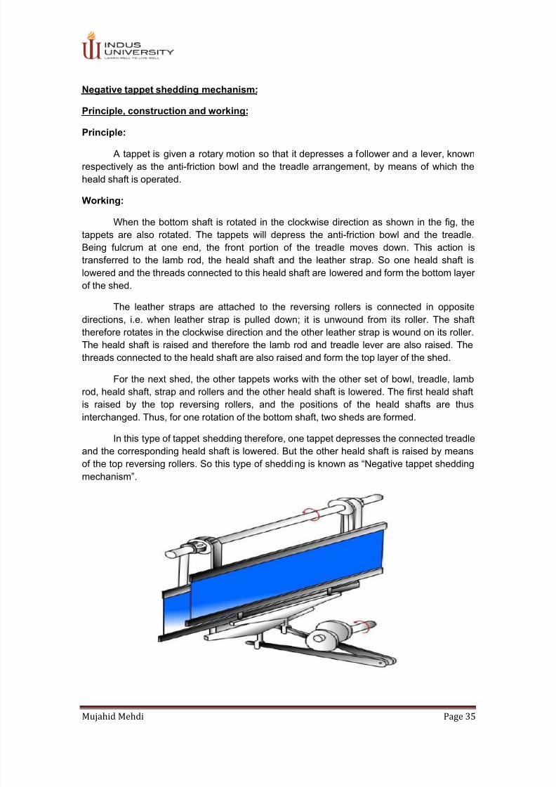
Working:

When the bottom shaft is rotated in the clockwise direction as shown in the fig, the

tappets are also rotated. The tappets will depress the anti-friction bowl and the treadle.

Being fulcrum at one end, the front portion of the treadle moves down. This action is

transferred to the lamb rod, the heald shaft and the leather strap. So one heald shaft islowered and the threads connected to this heald shaft are lowered and form the bottom layer

of the shed.

The leather straps are attached to the reversing rollers is connected in opposite

directions, i.e. when leather strap is pulled down; it is unwound from its roller. The shaft

therefore rotates in the clockwise direction and the other leather strap is wound on its roller.

The heald shaft is raised and therefore the lamb rod and treadle lever are also raised. The

threads connected to the heald shaft are also raised and form the top layer of the shed.

For the next shed, the other tappets works with the other set of bowl, treadle, lamb

rod, heald shaft, strap and rollers and the other heald shaft is lowered. The first heald shaft

is raised by the top reversing rollers, and the positions of the heald shafts are thus

interchanged. Thus, for one rotation of the bottom shaft, two sheds are formed.

In this type of tappet shedding therefore, one tappet depresses the connected treadle

and the corresponding heald shaft is lowered. But the other heald shaft is raised by means

of the top reversing rollers. So this type of shedding is known as “Negative tappet sheddingmechanism”. 

7/24/2019 Complete Textile Mechanics Lab

http://slidepdf.com/reader/full/complete-textile-mechanics-lab 36/47


Mujahid Mehdi Page 36

Timings and Setting:

1. Turn the crank to the top center position.

2. Fix the anti-friction bowls to the treadle levers; they should move freely in the slots.

3. Fix the treadle levers with a bracket to the back-rail of the loom.

4. Set the grid and grid bracket to the front rail of the loom.

5. Make sure that the tappets with the lower throw are fixed to the bottom shaft at the

starting handle side.

6. Fix the top reversing rollers to the top reversing roller shaft to be equidistant from the

ends and at the same time ensure that the connecting screws of the rollers are

symmetrical about the central axis of the shaft when the heald shafts are at the same

level. The roller of smaller diameter is always connected to the front heald shaft.

7. The heald shafts are connected to the top reversing rollers by means of cords and

leather straps. The leather straps are connected to the rollers, such that when one of

them winds on its roller the other strap unwinds from its roller and vice versa.

8. Lamb rods are connected to the heald shafts by cords.

9. Adjust the tappets on the bottom shaft and make sure of the following points:

  The tappets with a bigger throw should be connected to the back heald shaft.

  The bowls should have perfect contact with the tappet surfaces.

  The treadles should be at the same level and parallel to each other at the top

center positions.

  Heald shafts: The hook of the lamb rod of the front heald shaft should be

connected to the first notch of the treadle lever which that of the back heald shaft

should be connected to the third notch. If the depth of shed is altered, the

connections of the hooks to the treadle levers can be changed.

Points to be observed:

1. Turn the crank shaft through two revolutions and make sure that the bowls are always in

contact with the tappets.

2. The heald shafts should not touch the side frames or the slay.

3. Turn the crank shaft to the bottom center and check the size of shed. The bottom line of

warp sheet or the heald eyes of the lowered heald shaft should have a clearance of 1

mm from the race board and the top.

Top reversing rollers:

The bigger reversing roller P is connected to the back heald shaft K and the smaller

roller N is connected to the front heald shaft J. This is shown in fig.

RESULTS:

1. Turn the crank shaft through two revolutions and make sure that the bowls are always in

contact with the tappets.

2. The heald shafts should not touch the side frames or slay.

3. Turn the crank shaft to the bottom center and check the size of shed. The bottom line ofwarp sheet or the heald eyes of the lowered heald shaft should have a clearance of 1

mm from the race board and the top.

7/24/2019 Complete Textile Mechanics Lab

http://slidepdf.com/reader/full/complete-textile-mechanics-lab 37/47


Mujahid Mehdi Page 37

REVIEW QUESTIONS:

1. Why do we change the number of tappets?

 _________________________________________________________________

2. What is role of tappets?

3. Define Negative Shedding?

FINAL CHECK LIST:

1. Clean your equipment / materials and workbench before you leave.

2. Close all covers, nuts and bolts, which were opened.

3. Greasing and oiling is essential for all moving parts.

4. Return all equipment and materials to their proper storage area.

5. Switch off the machine before dismantling any part of the machine.

6. Submit your answers to questions together with your data, calculations and results

before the next lab.

7/24/2019 Complete Textile Mechanics Lab

http://slidepdf.com/reader/full/complete-textile-mechanics-lab 38/47


Mujahid Mehdi Page 38

LAB EXPERIMENT 12 DOBBY SHEDDING SYSTEM 

To study the power transfer in the dobby shedding system of

weaving loom 

PERFORMANCE OBJECTIVE

Upon successful completion of this experiment the student I‟ll be able to

i. Operate Dobby shedding mechanism.

ii. Construct various designs by their own choice on dobby weaving looms.

EQUIPMENT/ MACHINES

Negative dobby shedding machine equipped on weaving loom.

THEORY

Since the production of the pattern on tappet shedding is limited to 8 or 12 heald

frame .A dobby shedding is one of improved mechanism allows you to change the weaving

style by using a section mechanism up to 24 healed frames.in this mechanism the healed

frame are all operated by jacks levers and occupy less space as compared to tappet

shedding mechanism The selection of mechanism controls the loom frame in the position of

maximum or minimum shed opening as per the lifting plan ,which is controlled by a pattern

chain or an electromagnetic system allows the users to change the fabrics specificationwithout changing any can mechanism .

Student Name: ____________________________________ ID No. ____________________

Signature of the lab tutor________________________ Date: _____________________

7/24/2019 Complete Textile Mechanics Lab

http://slidepdf.com/reader/full/complete-textile-mechanics-lab 39/47


Mujahid Mehdi Page 39

It is very easy to change pattern chain whenever a new design required be weaving;

providing of course, the number of heald frames and order of drawing-in, there are many

types of dobbies available for weaving varieties of fabrics; there are also classified positive

and negative dobbies in action. Dobbies are further subdivided into;

i. 1-Single lift single jack dobby

ii. 2-Double lift double jack dobby

Single lift single jack dobby characterized by effecting healed frames movement

takes place by the same machine elements for every pick consequently and this element

must be ready for operation for any requited pick in the selected patterns whereas double

lift dobby is provided with two elements having opposite working cycle .one elements

responsible for even number of pick and the other for the odd number of picks .There is

available time taken by two crank revolutions of the loom for the selection of the healed

frames.

Construct ion:  

  In SAMHO (origin: Korea) dobby, a driving shaft is connected with a T-lever. The

shaft gets motion from a bottom shaft

  Two draw knives are connected with T-lever, at up and down & tey are engaged with

2 hooks

  The upper hook is supported by plain feeler via a needle and bottom hook by hooked

feeler

  Below the feelers, a pattern cylinder with pattern chain and peg plan is placed

  The hooks are joined with a driving lever which is pivoted. The driving lever is

connected with a jack lever via a connecting lever. The jack lever is pivoted at one

end.

  Jack lever is attached with heald frame via guide roller and connecting cord. Heald

frame is connected with a spring for lowering.

7/24/2019 Complete Textile Mechanics Lab

http://slidepdf.com/reader/full/complete-textile-mechanics-lab 40/47


Mujahid Mehdi Page 40

PROCEDURE/METHOD

The working of different parts of this dobby as:

1. When the driving shaft moves up and down, T-lever gives inward & outward

movement.

2. According to fabric design, when peg came in contact with the plain feeler, then the

left portion of feeler is raised and the right portion being lowered. As hooks are

supported with feeler, hooks are lowered and upper hook came in contact with upper

knife.

3. In this state, when connecting rod moves down, the upper draw knife moves left. As

a result upper hook also moves to the left. As driving lever is joined with jack lever

 joined with connecting lever, the jack lever moves to left at the same time. Thus the

heald shaft is lifted.

4. Similarly, when the right end of hooked feeler is lowered, then lower hook came in

contact with lower knife. In this state, when connecting rod moves up and the bottom

portion of T-lever moves to the left side.

5. As a result, bottom portion of driving lever moves to the left & the top portion of the

 jack lever moves to the left. Hence the heald shaft is again lifted.

6. The shaft will therefore be lowered with the help of return spring and will remain

down for next pick.

CALCULATION

If we produce 3/1 twill weaves which is possible to produce on dobby shedding motion. We

shall require minimum 8 lags with 4 repeats of design. As there is straight draft so the

drawing in order for war 1,2,3,4 and repeats are useful till the last warp end.

OBSERVATIONS:

 _________________________________________________________________________ 

 _________________________________________________________________________ 

 ________________________________________________________________________  

7/24/2019 Complete Textile Mechanics Lab

http://slidepdf.com/reader/full/complete-textile-mechanics-lab 41/47


Mujahid Mehdi Page 41

REVIEW QUESTIONS:

1- What is maximum range design repeats are possible to produce on dobby shedding

mounted on the looms at our laboratory and names different design possible to

weave?

 ___________________________________________________________________ 

 ___________________________________________________________________ 

 __________________________________________________________________

2- What are advantages of early shedding?

 ___________________________________________________________________ 

 ___________________________________________________________________ 

 __________________________________________________________________

3- What are advantages of late shedding?

 ___________________________________________________________________ 

 ___________________________________________________________________ 

 __________________________________________________________________

Final Check List:

1- Clean your equipment /material and tools before you leave.

2- Close all covers, nut bolts tightly which were opened.

3- Returns all tolls, equipment and material to their proper storage area.

4- Submit your answer to question together with your date, calculation, and results

before the next laboratory.

7/24/2019 Complete Textile Mechanics Lab

http://slidepdf.com/reader/full/complete-textile-mechanics-lab 42/47


Mujahid Mehdi Page 42

LAB EXPERIMENT 13 SHUTTLE PICKING MECHANISM 

TO STUDY THE POWER TRANSFER IN THE PICKING SYSTEM OF

SHUTTLE WEAVING LOOM 

PERFORMANCE OBJECT:

Upon successful completion of this experiment, the student will be able to:

i) Understand working of various picking mechanism.

ii) Learn the setting of under pick motion.

EQUIPMENT / MACHINES:

Under picking loom mechanism on conventional shuttle loom.

DISCUSSION / THEORY:

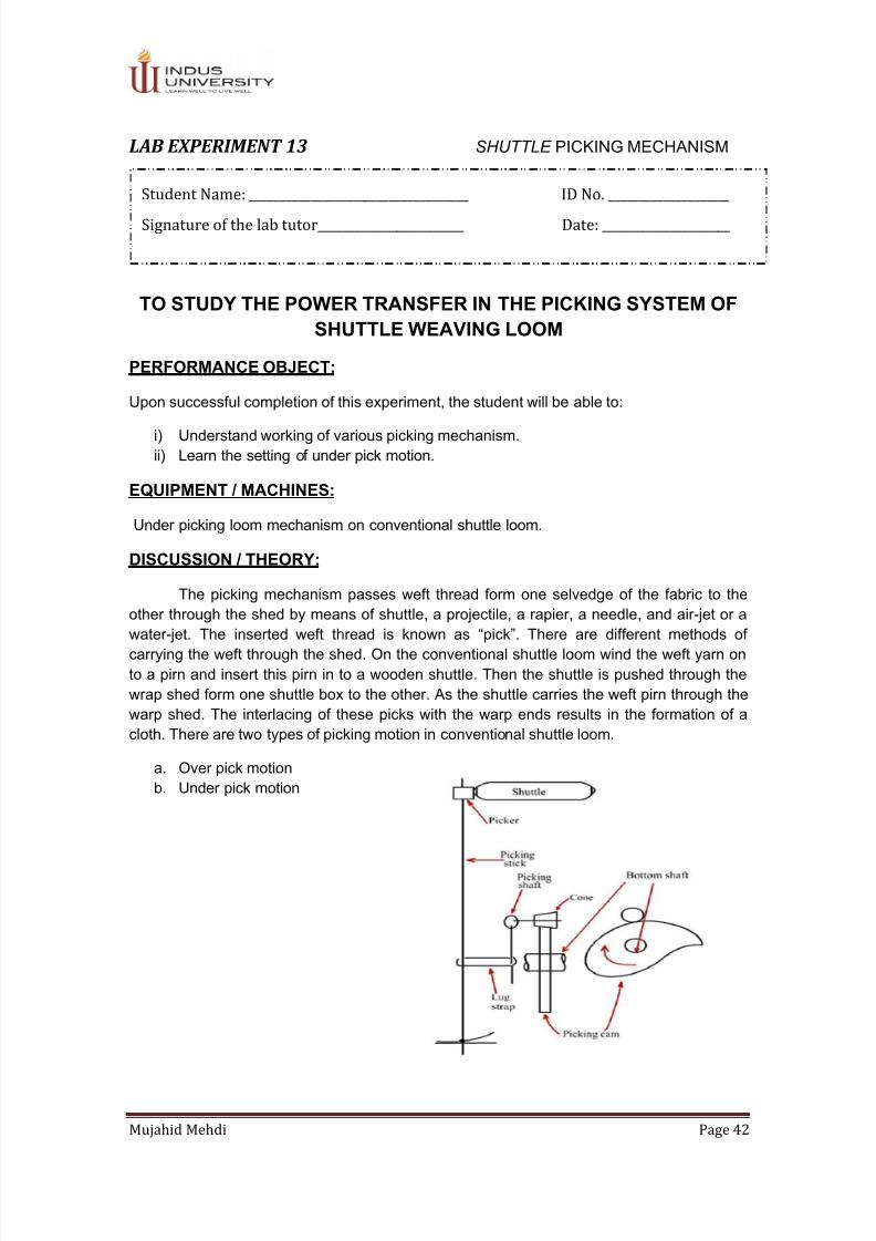
The picking mechanism passes weft thread form one selvedge of the fabric to the

other through the shed by means of shuttle, a projectile, a rapier, a needle, and air-jet or awater- jet. The inserted weft thread is known as “pick”. There are different methods ofcarrying the weft through the shed. On the conventional shuttle loom wind the weft yarn on

to a pirn and insert this pirn in to a wooden shuttle. Then the shuttle is pushed through the

wrap shed form one shuttle box to the other. As the shuttle carries the weft pirn through the

warp shed. The interlacing of these picks with the warp ends results in the formation of a

cloth. There are two types of picking motion in conventional shuttle loom.

a. Over pick motion

b. Under pick motion

Student Name: ____________________________________ ID No. ____________________

Signature of the lab tutor________________________ Date: _____________________

7/24/2019 Complete Textile Mechanics Lab

http://slidepdf.com/reader/full/complete-textile-mechanics-lab 43/47


Mujahid Mehdi Page 43

PROCEDURE / METHOD

In our laboratory we have done practical on side lever under pick motion on shuttle

loom as we know there are two types of under pick motion; cone lever pick and side leverpick. The side lever pick is simplest used for all types of fabric. All parts are fitted outside of

the loom frame, so easy to maintain the motion comprises of the following part:

1. A wooden side lever.

2. A picking shoe fixed on the side lever.

3. A wooden picking stick fixed to iron shoe.

4. The picker is loose on the picking stick and guided between the bottom grooves of

the shuttle box.

5. A bowl strikes down the side as it revolve with the striking device fixed to the bottom

shaft.

6. A spring attach to the bottom of the iron shoe returns picking stick after each forward

strike.

Settings of side lever under pick motion

i. Picking starts when the slay is about 60mm back from the front dead center and the

picking bowl comes in contact with the nose.

ii. Stroke i.e. movement of the picker, when the loom is rotated by hands depands upon

the width of the loom. Picking motion of the off side of the loom given about 5 cm

more movement than to the starting handle side.

iii. Picking stick return spring should be sufficient to bring it back after picking.

TEST REPORTS / RESULT

The length of strokes

Reed space in cm 40 44 48 52 56 60 64

Stroke length in cm 27 28 28 29 30 31 31

OBSERVATIONS:

 _________________________________________________________________________ 

 _________________________________________________________________________ 

 ________________________________________________________________________  

7/24/2019 Complete Textile Mechanics Lab

http://slidepdf.com/reader/full/complete-textile-mechanics-lab 44/47


Mujahid Mehdi Page 44

REVIEW QUESTION

1. Which picking mechanism is superior as per its working?

 ___________________________________________________________________ 

 ___________________________________________________________________ 

 __________________________________________________________________

2. What are the demerits of under pick mechanism?

 ___________________________________________________________________ 

 ___________________________________________________________________ 

 __________________________________________________________________

3. What is the use of buffer?

 ___________________________________________________________________ 

 ___________________________________________________________________ 

 __________________________________________________________________

FINAL CHECKLIST

1. Clean your apparatus and work bench before you leave.

2. Keep the apparatus back to their proper places.

3. Submit your answers to questions and results before the next laboratory experiment

according to the time table.

7/24/2019 Complete Textile Mechanics Lab

http://slidepdf.com/reader/full/complete-textile-mechanics-lab 45/47


Mujahid Mehdi Page 45

LAB EXPERIMENT 14 RAPIER PICKING MECHANISM 

To study the power transfer in the picking system of

rapier weaving loom

Performance objective:

Upon successful completion of this experiment, the student will be able to:

I.  Understand the working principle of rapier weaving machine.

II.  Know the advantage and disadvantages of rapier weaving machine.

EQUIPMENT /MACHINE

  Rapier Weaving Machine.

DISCUSSION / THEORY

Insertion of weft by rapier is a mechanically modern and refined version of the primitivemethod of fabric producing in which the weft was secured in a slot of a stick. The loom

equipped in our laboratory the gripped heads are attached to rapiers, which are flexible

tapes. The rapiers are made of coated steel or reinforced high performance man-made fiber

the major advantage of rapier weft insertion system is easy and reliable weft transmission to

the giver rapier even in the system on which the end of weft yarn is firmly gripped. In rapier

system the initial speed of the giver rapier is very low and enough time is available for weft

engagement with rapier. As the weft is placed in the way of rapier, the weft feed mechanism

need not be very precise. This also explains why the weft color change is so easy and

simple on rapier weaving machine.

Different makers have different ideas for driving the rapier. The main aims are

  To reduce the cost of manufacture.

  To make it simple, durable and ease of maintenance.

  To make in versatile.

  To reduce floor space.

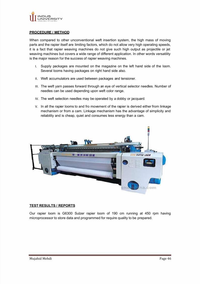
Sulzer Ruti G6300 rapier loom available at our laboratory will weave not only fashion fabric

with as many as a weft color but also furnishing fabrics, simple print base fabrics and denims

as efficiently as light to heavy weight industrial fabrics.

Student Name: ____________________________________ ID No. ____________________

Signature of the lab tutor________________________ Date: _____________________

7/24/2019 Complete Textile Mechanics Lab

http://slidepdf.com/reader/full/complete-textile-mechanics-lab 46/47


Mujahid Mehdi Page 46

PROCEDURE / METHOD

When compared to other unconventional weft insertion system, the high mass of moving

parts and the rapier itself are limiting factors, which do not allow very high operating speeds,

it is a fact that rapier weaving machines do not give such high output as projectile or jet

weaving machines but covers a wide range of different application. In other words versatility

is the major reason for the success of rapier weaving machines.

I.  Supply packages are mounted on the magazine on the left hand side of the loom.

Several looms having packages on right hand side also.

II.  Weft accumulators are used between packages and tensioner.

III.  The weft yarn passes forward through an eye of vertical selector needles. Number of

needles can be used depending upon weft color range.

IV.  The weft selection needles may be operated by a dobby or jacquard.

V.  In all the rapier looms to and fro movement of the rapier is derived either from linkage

mechanism or from a cam. Linkage mechanism has the advantage of simplicity and

reliability and is cheap, quiet and consumes less energy than a cam.

TEST RESULTS / REPORTS

Our rapier loom is G6300 Sulzer rapier loom of 190 cm running at 450 rpm having

microprocessor to store data and programmed for require quality to be prepared.

7/24/2019 Complete Textile Mechanics Lab

http://slidepdf.com/reader/full/complete-textile-mechanics-lab 47/47


REVIEW QUESTION

1. What are the advantages of linkage mechanism of driving of rapier?

 ___________________________________________________________________ 

 ___________________________________________________________________ 

 __________________________________________________________________

2. How many number of selection needles are used and why?

 ___________________________________________________________________ 

 ___________________________________________________________________ 

 __________________________________________________________________

FINAL CHECKLIST

4. Clean your apparatus and work bench before you leave.

5. Keep the apparatus back to their proper places.

6. Submit your answers to questions and results before the next laboratory experiment

according to the time table.


Recommended