443
CompleteView™ Administrator Manual CompleteView™ Version 4.7

CompleteView™ Administrator Manual CompleteView™ Version 4.7

Salient Systems Corporation CompleteView™ Administrators User Manual
Salient Systems Corporation i Simple.Scalable.Security
©2016 Salient Systems Corporation. All Rights Reserved Company and product names mentioned are registered trademarks of their respective owners.

Salient Systems Corporation CompleteView™ Administrators User Manual
Salient Systems Corporation ii Simple.Scalable.Security
End User License Agreement
Salient CompleteView™ SOFTWARE LICENSE:
1. GRANT OF LICENSE: Salient grants to you the right to use one (1) copy of the Salient CompleteView Server SOFTWARE on one (1) computer. Salient grants to you the right to use one (1) copy of the Salient CompleteView Client SOFTWARE on any numbers of computers, provided that the Salient CompleteView Client is solely used to connect to a Salient CompleteView Server. The SOFTWARE is in "use" on a computer when it is loaded into temporary memory (i.e. RAM) or installed into permanent memory (e.g. hard disk, CD‐ROM or other storage device) of that computer.
2. COPYRIGHT: The SOFTWARE is owned by Salient and/or its licensor(s), if any, and is protected by copyright laws and international treaty provisions. Therefore, you must treat the SOFTWARE like any other copyrighted material (e.g. a book or a musical recording) except that you may either (a) make a copy of the SOFTWARE solely for backup or archival purposes or (b) transfer the SOFTWARE to a single hard disk provided you keep the original solely for backup purposes.
3. OTHER RESTRICTIONS: You may not rent, lease or sublicense the SOFTWARE but you may transfer SOFTWARE and accompanying written materials on a permanent basis provided that you retain no copies and the recipient agrees to the terms of this agreement. You may not reverse engineer, decompile, or disassemble the SOFTWARE. If the SOFTWARE is an update or has been updated, any transfer must include the most recent update and all previous versions.
4. THIRD PARTY Software: The SOFTWARE may contain third party software, which requires notices and/or additional terms and conditions. Such required third party software notices and/or additional terms and conditions are located in the readme file or other product documentation. By accepting this license agreement, you are also accepting the additional terms and conditions, if any, set forth therein.
5. TERMINATION: This License is effective until terminated. Your rights under this License will terminate automatically without notice from Salient if you fail to comply with any term(s) of this License. Upon the termination of this License, you shall cease all use of the SOFTWARE and destroy all copies, full or partial, of the SOFTWARE.
6. GOVERNING LAW: This agreement shall be deemed performed in and shall be construed by the laws of United States, Texas.
7. DISCLAIMER: PROCUREMENT AND USE OF THE SOFTWARE ENTITLES BOTH SALIENT AND THE USER TO CERTAIN RIGHTS AND PRIVILEGES. CONTINGENT UPON STATE, MUNICIPAL, AND FEDERAL STATUTES. EXPECTATIONS OF FUNCTIONALITY, VIABILITY, USABILITY, AND/OR PERFORMANCE OF THE SOFTWARE MAY BE LIMITED OR OTHERWISE GOVERNED PURSUANT TO THE APPLICABLE SOFTWARE WARRANTY. THE SPECIFIC AGREEMENT BETWEEN SALIENT AND THE END USER MAY BE CHANGED WITHOUT NOTICE AT ANY TIME. ANY AND ALL UPDATES TO THE AGREEMENT MAY BE FOUND ON THE SALIENT WEBSITE AT http://www.salientsys.com.

Salient Systems Corporation CompleteView™ Administrators User Manual
Salient Systems Corporation iii Simple.Scalable.Security
Contents 1. About This Manual ........................................................................................................... 1
Scope ........................................................................................................................................... 1
Audience ...................................................................................................................................... 1
Document Conventions ............................................................................................................... 1
Typographical Conventions ..................................................................................................... 1
Reader Alerts ........................................................................................................................... 4
Screenshots .............................................................................................................................. 5
Illustrations .............................................................................................................................. 6
Command Line Examples ....................................................................................................... 7
Acronyms and Abbreviations ...................................................................................................... 9
2. System Requirements ..................................................................................................... 11
CompleteView™ Client Requirements ..................................................................................... 11
CompleteView™ Server Requirements .................................................................................... 11
3. VMS System Functional Overview .................................................................................. 12
4. VMS System Network Communications .......................................................................... 17
5. CompleteView™ VMS Software Suite, Overview ............................................................ 19
CV Server Suite Components ................................................................................................... 19
CV Client Suite Components .................................................................................................... 20
6. Microsoft® Windows® Integration .................................................................................. 23
CompleteView™ Windows® Applications .............................................................................. 24
CompleteView™, Windows® System Services ........................................................................ 25
Accessing CompleteView™ Windows® System Services ................................................... 26
CompleteView™, Active Directory® Connector ..................................................................... 30
Windows® Firewall .................................................................................................................. 32
Mandatory Firewall Exceptions............................................................................................. 32
Optional Firewall Exceptions ................................................................................................ 33
Camera Firewall Exceptions .................................................................................................. 33
Alarm Device and Other Exceptions ..................................................................................... 34
About Configuring Windows Firewall Exceptions ............................................................... 34
Configure Firewall Exceptions .............................................................................................. 35
Configure Windows® Firewall with Advanced Security ...................................................... 36

Salient Systems Corporation CompleteView™ Administrators User Manual
Salient Systems Corporation Simple.Scalable.Security
7. Connecting To CompleteView™ Servers .......................................................................... 42
Connect To Server Dialog ......................................................................................................... 45
CompleteView™ Utility Programs ........................................................................................... 46
8. CompleteView™ License Management ........................................................................... 47
CompleteView™ License keys ................................................................................................. 49
Obtaining a Hardware License Key ....................................................................................... 49
Obtaining a Software License Key ........................................................................................ 49
Retrieving the Server Product ID .......................................................................................... 50
Managing Feature Keys ............................................................................................................ 52
Accessing Feature Keys and Product ID ............................................................................... 52
Adding Feature Keys ............................................................................................................. 55
Removing Feature Keys ........................................................................................................ 56
Moving Camera Feature Keys ............................................................................................... 57
Moving Camera Feature Keys between Software License Keys .......................................... 57
9. Software Installation ...................................................................................................... 58
CompleteView™ Installation Wizard ....................................................................................... 58
Installing Gen I Capture Card Drivers ................................................................................... 68
Installing Gen II Capture Card Drivers ................................................................................. 69
10. System Configuration ..................................................................................................... 70
System Components .................................................................................................................. 71
Edge devices .......................................................................................................................... 71
Video client components ....................................................................................................... 72
The Video server components ............................................................................................... 73
Configuration Files .................................................................................................................... 74
The Server configuration file ................................................................................................. 74
The Client configuration file ................................................................................................. 75
11. CompleteView™ Configuration Utility ............................................................................ 76
Configuration Sessions .............................................................................................................. 76
To start the Configuration Utility .......................................................................................... 77
To create a server configuration session ................................................................................ 78
To create a client configuration session ................................................................................ 79
To open a saved configuration session .................................................................................. 81
Configuration Consoles ............................................................................................................. 82

Salient Systems Corporation CompleteView™ Administrators User Manual
Salient Systems Corporation Simple.Scalable.Security
Server Configuration Console ................................................................................................... 84
Server Configuration Console, System Menu ....................................................................... 85
Server Configuration Console, Toolbar ................................................................................. 90
Server Configuration Console Tree ....................................................................................... 93
Server Configuration Console Details Pane .......................................................................... 95
Client Configuration Console .................................................................................................... 96
Client Configuration Console System Menu ......................................................................... 97
Client Configuration Toolbar .............................................................................................. 102
Client Configuration Console Tree ...................................................................................... 105
Client Configuration Details Pane ....................................................................................... 107
12. Configuring CompleteView™ Servers ............................................................................ 108
Managing Server Configurations ............................................................................................ 109
To add a Server Configuration ............................................................................................ 111
To edit a Server Configuration credentials .......................................................................... 112
To delete a Server Configuration ......................................................................................... 114
To access the server license management dialogue ............................................................. 114
To reload a server configuration .......................................................................................... 115
To save a server configuration ............................................................................................. 116
To load a server configuration ............................................................................................. 117
To save a Server Configuration ........................................................................................... 118
To restore a server configuration backup ............................................................................ 119
To save a server configuration backup ................................................................................ 120
To access User functions from the server configuration menu ........................................... 121
To access Camera functions from the server configuration menu ...................................... 121
To access Alarm Device functions from the server configuration menu ............................ 121
To access Volume functions from the server configuration menu ...................................... 121
To access Schedule functions from the server configuration menu .................................... 122
Configuring the Server Configuration ..................................................................................... 123
Server Configurations, Server General Settings Window ................................................... 123
Server Configurations, Server Logging Window ................................................................ 126
Server Configuration, Server Email Window...................................................................... 128
Server Configuration, Server Tracking Window ................................................................. 130
Server Configuration, Server Integrations Window ............................................................ 132

Salient Systems Corporation CompleteView™ Administrators User Manual
Salient Systems Corporation Simple.Scalable.Security
Server Configuration, Axis One-Click Window ................................................................. 134
Server Configuration, Web Server ...................................................................................... 136
Server Configuration, Users/Groups ....................................................................................... 137
Users/Groups Functional Overview .................................................................................... 137
Creating and Managing Server Users/Groups ..................................................................... 138
Configuring Server Users/Groups ....................................................................................... 141
Server Configurations, Cameras ............................................................................................. 149
Analog Cameras .................................................................................................................. 149
IP Cameras ........................................................................................................................... 150
QuickTrack Cameras ........................................................................................................... 151
Camera Pan Tilt Zoom (PTZ) Control ................................................................................ 151
Advanced Camera Features ................................................................................................. 151
CompleteView™ Advanced Camera Features .................................................................... 152
Creating and Managing Camera Objects ............................................................................. 154
Configuring Cameras ........................................................................................................... 169
Audio Devices ......................................................................................................................... 216
Alarm Devices ......................................................................................................................... 218
Creating and Managing Alarm Devices .............................................................................. 218
Configuring Alarm Devices................................................................................................. 220
Serial Ports .............................................................................................................................. 227
Serial Ports Functional Overview ........................................................................................ 227
Creating and Managing Serial Ports .................................................................................... 228
Configuring Serial Ports ...................................................................................................... 229
Video Volumes ........................................................................................................................ 233
Video Volumes Functional Overview ................................................................................. 235
Creating and Managing Volumes ........................................................................................ 241
Configuring Video Volumes ............................................................................................... 244
Schedules ................................................................................................................................. 258
Schedules Functional Overview .......................................................................................... 258
Creating and Managing Schedules ...................................................................................... 260
Configuring Schedules ........................................................................................................ 264
NVRs & DVRs ........................................................................................................................ 273
Adding an NVR ................................................................................................................... 273

Salient Systems Corporation CompleteView™ Administrators User Manual
Salient Systems Corporation Simple.Scalable.Security
Adding Cameras to an NVR ................................................................................................ 274
Server Configurations, Diagnostic/Reporting ......................................................................... 277
Diagnostic/Reporting, Logging Window ............................................................................ 277
Diagnostic/Reporting, Cameras Window ............................................................................ 281
Diagnostic/Reporting, Configurations Window .................................................................. 283
13. Configuring CompleteView™ Clients ............................................................................. 287
Managing Client Configurations ............................................................................................. 289
To add a Client Configuration ............................................................................................. 291
To edit Client Configuration Credentials ............................................................................ 293
To delete a Client Configuration ......................................................................................... 295
To reload a Client Configuration ......................................................................................... 296
To save a Client Configuration ............................................................................................ 297
To load a Client Configuration ............................................................................................ 298
To save a client configuration to a file ................................................................................ 301
To restore a client configuration backup ............................................................................. 303
To save a client configuration backup ................................................................................. 304
To access User functions from the client configuration menu ............................................ 304
To access View functions from the client configuration menu ........................................... 305
To access Map functions from the client configuration menu ............................................ 305
To access Server functions from the client configuration menu ......................................... 305
To access Zone functions from the client configuration menu ........................................... 305
Configuring the Client Configuration ..................................................................................... 307
Client Configuration, Client General Settings Window ...................................................... 307
Client Configuration, Zones/Sites ........................................................................................... 309
Creating and Managing Client Zones/Sites ......................................................................... 310
Configuring Zones/Sites ...................................................................................................... 314
Client Configuration, Users/Groups ........................................................................................ 318
Client Users/Groups Functional Overview.......................................................................... 319
Creating and Managing Client Users/Groups ...................................................................... 320
Configuring Client Users and Groups ................................................................................. 323
Client Configuration, Servers .................................................................................................. 329
Client Configuration, Servers Functional Overview ........................................................... 329
Client Configuration, Creating and Managing Servers ....................................................... 329

Salient Systems Corporation CompleteView™ Administrators User Manual
Salient Systems Corporation Simple.Scalable.Security
Client Configuration, Configuring Servers ......................................................................... 336
Client Configuration, View Layouts ....................................................................................... 338
Views Layouts Functional Overview .................................................................................. 338
Creating and Managing View Layouts ................................................................................ 340
Configuring View Layouts .................................................................................................. 351
Client Configuration, Maps ..................................................................................................... 360
Creating and Managing Map Objects .................................................................................. 360
Configuring Maps ................................................................................................................ 362
14. CompleteView™ Server Process Maintenance .............................................................. 372
CompleteView Server Service ................................................................................................ 375
Server Service Maintenance Tasks ...................................................................................... 376
CompleteView Administrative Service ................................................................................... 384
Administrative Service Maintenance Tasks ........................................................................ 385
CompleteView Configuration Server ...................................................................................... 390
ConfigServer Service Maintenance Tasks ........................................................................... 392
Appendices .......................................................................................................................... 397
Additional Resources .............................................................................................................. 427

Salient Systems Corporation CompleteView™ Administrators User Manual
Salient Systems Corporation ix Simple.Scalable.Security
List of Figures Figure 1-1, Sample Screenshot ....................................................................................................... 5 Figure 1-2, Sample Drawing Image ................................................................................................ 6 Figure 1-3, Command Line Example Format ................................................................................. 7 Figure 1-4, Windows(R) CLI Shell ................................................................................................ 8 Figure 3-1, VMS Simplified Block Diagram ................................................................................ 12 Figure 4-1, VMS Network Communications ................................................................................ 17 Figure 5-1, CompleteView Software Suite ................................................................................... 19 Figure 6-1, Service Properties Dialogue ....................................................................................... 28 Figure 6-2, Active Directory Authentication ................................................................................ 30 Figure 6-3, Configure Firewall Exception .................................................................................... 36 Figure 6-4, MS Firewall with advanced security snap-in ............................................................. 41 Figure 7-1, Server Management Connections .............................................................................. 42 Figure 7-2, Client Server Transmit Datagram Flow ..................................................................... 43 Figure 7-3, Connect To Server Dialogue ...................................................................................... 45 Figure 8-1, Single Server License Model ..................................................................................... 47 Figure 8-2, Multi-Server License Model ...................................................................................... 48 Figure 8-3 License Not Found Dialogue ...................................................................................... 51 Figure 8-4 Feature Keys Dialogue ................................................................................................ 52 Figure 8-5 Access Feature keys .................................................................................................... 54 Figure 10-1, VMS System Component Relationships .................................................................. 70 Figure 10-2, Server Configuration File ......................................................................................... 74 Figure 11-1, Connect To Server Dialogue .................................................................................... 78 Figure 11-2, Client Configuration Dialogue ................................................................................. 79 Figure 11-3, Open session File Dialogue ...................................................................................... 81 Figure 11-4, Server Configuration Console .................................................................................. 84 Figure 11-5, Server Configuration Menu...................................................................................... 88 Figure 11-6, Server Configuration Toolbar .................................................................................. 90 Figure 11-7, Server Configuration Console Tree ......................................................................... 93 Figure 11-8, Server Configuration Console Details Pane ............................................................. 95 Figure 11-9, Client Configuration Console .................................................................................. 96 Figure 11-10, Client Configuration Menu Bar ............................................................................. 97 Figure 11-11, Client Configuration Menu .................................................................................. 100 Figure 11-12, Client Configuration Toolbar ............................................................................... 102 Figure 11-13, Client Toolbar, File Buttons ................................................................................. 102 Figure 11-14, Client Toolbar, Configuration Buttons ................................................................ 103 Figure 11-15, Client Configuration Console Tree ...................................................................... 105 Figure 11-16, Client Configuration Details Pane ....................................................................... 107 Figure 12-1, Server Menu ........................................................................................................... 109 Figure 12-2, Add Server Configuration Dialogue ...................................................................... 111 Figure 12-3, Question Dialogue .................................................................................................. 112 Figure 12-4, Information Dialogue ............................................................................................. 116 Figure 12-5, Out of Date Dialogue ............................................................................................. 116 Figure 12-6, Server Configuration - General .............................................................................. 123 Figure 12-7, Server Configuration – Logging Window .............................................................. 126

Salient Systems Corporation CompleteView™ Administrators User Manual
Salient Systems Corporation Simple.Scalable.Security
Figure 12-8, Server Configuration - Email ................................................................................. 128 Figure 12-9, Email Configuration ............................................................................................... 129 Figure 12-10, Server Configuration - Tracking .......................................................................... 130 Figure 12-11, Server Configuration - Integrations ..................................................................... 132 Figure 12-12, Server Configuration - Axis One Click ............................................................... 134 Figure 12-13, Server Configuration – Web Server ..................................................................... 136 Figure 12-14, Users/Groups Administration Tab ....................................................................... 141 Figure 12-15, User/Group Membership Box .............................................................................. 143 Figure 12-16, Users/Groups Camera Tab ................................................................................... 144 Figure 12-17, Users/Groups Advanced Window ........................................................................ 147 Figure 12-18, Cameras Menu ..................................................................................................... 155 Figure 12-19, Live View Dialogue ............................................................................................. 158 Figure 12-20, Move or Copy IP Cameras ................................................................................... 161 Figure 12-21, Camera Search/Add Dialogue .............................................................................. 165 Figure 12-22, Camera Edit Dialogue .......................................................................................... 167 Figure 12-23, Cameras General Tab ........................................................................................... 169 Figure 12-24, Cameras Volumes Window .................................................................................. 178 Figure 12-25, Cameras IP Window ............................................................................................ 180 Figure 12-26, Use On-Camera Alerting ...................................................................................... 184 Figure 12-27, Camera Alarm Event Configuration .................................................................... 185 Figure 12-28, Cameras PTZ Window ......................................................................................... 187 Figure 12-29, Cameras Motion/Alarm Window ......................................................................... 192 Figure 12-30, Actions Dialogue .................................................................................................. 197 Figure 12-31, Actions Dialogue Controls ................................................................................... 198 Figure 12-32, Add Action Dialogue ........................................................................................... 199 Figure 12-33, Add Action Dialogue Controls............................................................................. 199 Figure 12-34, Live View ............................................................................................................. 201 Figure 12-35, Cameras Audio Window ...................................................................................... 203 Figure 12-36, Cameras Email Window ...................................................................................... 205 Figure 12-37, Cameras Analytics Window ................................................................................. 208 Figure 12-38, Cameras Edge Storage Window........................................................................... 210 Figure 12-39, Edge Storage Settings .......................................................................................... 212 Figure 12-40, Edge Storage Synchronization Options ............................................................... 212 Figure 12-41, Cameras Advanced tab ......................................................................................... 214 Figure 12-42, Audio Devices Settings Tab ................................................................................. 216 Figure 12-43, Alarm Device Menu ............................................................................................. 218 Figure 12-44, Alarm Devices IP Tab .......................................................................................... 220 Figure 12-45, Alarm Devices Inputs tab ..................................................................................... 222 Figure 12-46, Alarm Devices Outputs Window ......................................................................... 224 Figure 12-47, Serial Ports Functional Diagram .......................................................................... 227 Figure 12-48, Serial Ports Settings Tab ...................................................................................... 230 Figure 12‐49, Volumes Menu ...................................................................................................... 242 Figure 12-50, Volumes General Tab .......................................................................................... 245 Figure 12-52, Volumes Cameras Tab ......................................................................................... 256 Figure 12-53, Schedules Menu ................................................................................................... 260

Salient Systems Corporation CompleteView™ Administrators User Manual
Salient Systems Corporation Simple.Scalable.Security
Figure 12-54, Schedule Error Dialogue ...................................................................................... 261 Figure 12-55, Schedule Type Dialogue ...................................................................................... 262 Figure 12-56, Schedules Edit Window ....................................................................................... 265 Figure 12-57, Schedules Manual Edit Controls .......................................................................... 268 Figure 12-58, Recording Plan Timescale Control ...................................................................... 271 Figure 12-58, NVR Right Click Menu ....................................................................................... 273 Figure 12-59, NVR Config Menu ............................................................................................... 273 Figure 12-60, NVR General Tab ................................................................................................ 274 Figure 12-61, NVR Camera Config Detail ................................................................................. 275 Figure 12-62, NVR Add Camera ................................................................................................ 276 Figure 12-63, Diagnostic/Reporting - Logging Details .............................................................. 277 Figure 12-64, Diagnostic/Reporting - Camera Details ............................................................... 281 Figure 12-65, Diagnostic/Reporting - Configurations Details .................................................... 283 Figure 12-66, Load Client Configuration Dialogue .................................................................... 285 Figure 13-1, Client Configuration Menu .................................................................................... 289 Figure 13-2, Client Container Menu Items ................................................................................. 290 Figure 13-3, Add Client Configuration Dialogue ....................................................................... 291 Figure 13-4, Question Dialogue .................................................................................................. 295 Figure 13-5, Information Dialogue ............................................................................................. 297 Figure 13-6, Load Client Configuration Dialogue ...................................................................... 298 Figure 13-7, Save Client Configuration ...................................................................................... 301 Figure 13-8, Client Container General Window ......................................................................... 307 Figure 13-9, Zones/Sites Menu ................................................................................................... 310 Figure 13-10, New Zone Dialogue ............................................................................................. 311 Figure 13-11, New Site Dialogue ............................................................................................... 312 Figure 13-12, Zones General Window ........................................................................................ 314 Figure 13-13, Zones Administration Tab.................................................................................... 315 Figure 13-14, Sites General Window .......................................................................................... 316 Figure 13-15, Sites Administration Window .............................................................................. 317 Figure 13-16, Client Configuration Utility Console Tree ........................................................... 318 Figure 13-17, Client Users/Groups Menu ................................................................................... 320 Figure 13-18, Users/Groups Administration Tab ....................................................................... 323 Figure 13-19, Users/Groups Credentials Window ...................................................................... 327 Figure 13-20, Servers Menu ....................................................................................................... 330 Figure 13-21, Add Server Dialogue ............................................................................................ 331 Figure 13-22, Add Server Question Dialogue ............................................................................ 331 Figure 13-23, Server Login Dialogue ......................................................................................... 332 Figure 13-24, Retrieving Server Information ............................................................................. 332 Figure 13-25, Change Server Address Dialogue ........................................................................ 333 Figure 13-26, Servers Cameras Window .................................................................................... 337 Figure 13-27, View Menus ......................................................................................................... 340 Figure 13-28, New View Dialogue ............................................................................................. 341 Figure 13-29, Autopopulate Views Dialogue ............................................................................. 342 Figure 13-30, View Object Menu ............................................................................................... 343 Figure 13-31, New View Dialogue ............................................................................................. 344

Salient Systems Corporation CompleteView™ Administrators User Manual
Salient Systems Corporation Simple.Scalable.Security
Figure 13-32, Autopopulate Views ............................................................................................. 345 Figure 13-33, Apply Template Warning ..................................................................................... 349 Figure 13-34, Delete Template Warning .................................................................................... 350 Figure 13-35, View Object General Settings Window ............................................................... 351 Figure 13-36, View Layout Object Edit Window ....................................................................... 352 Figure 13-37, View Layout Add Camera ................................................................................... 354 Figure 13-38, Add Map Dialogue ............................................................................................... 358 Figure 13-39, Web page Dialogue .............................................................................................. 359 Figure 13-40, Map Menu ............................................................................................................ 360 Figure 13-41, Maps Open File Dialogue .................................................................................... 363 Figure 13-42, Map Edit Window ................................................................................................ 366 Figure 13-43, Map Camera Live View ....................................................................................... 369 Figure 14-1, Server Package Selection ....................................................................................... 372 Figure 14-2, Installation Directory Listing ................................................................................. 374 Figure 14-3, Server Service Network Communications ............................................................. 375 Figure 14-4, CompleteView Server Service ............................................................................... 376 Figure 14-5, CompleteView Admin Service .............................................................................. 384 Figure 14-6, Select Admin Service ............................................................................................. 385 Figure 14-7, CompleteView™ Config Server Service ............................................................... 390 Figure 14-8, Select Config Server Service ................................................................................. 391 Figure 14-9, Axis Camera Basic Configuration ......................................................................... 402 Figure 14-10, Axis Camera Plain Config Page ........................................................................... 403 Figure 14-11, Axis Camera Image Group Settings ..................................................................... 404 Figure 14-12, Events Configuration Web Page .......................................................................... 406 Figure 14-13, Event Configuration/Recipient Setup .................................................................. 407 Figure 14-14, Action Rules Setup ............................................................................................... 408 Figure 14-15, Action Rule Dialogue ........................................................................................... 409 Figure 14-16, Action Rule Custom Parameters .......................................................................... 410 Figure 14-17, Symmetry VCA Setup.......................................................................................... 412 Figure 14-18, Symmetry CompleteView Alert Setup................................................................. 413 Figure 14-19, Symmetry Alarm Event Selection ....................................................................... 413 Figure 14-20, Symmetry Motion and Alarm Timings ................................................................ 414 Figure 14-21, DI Event Setup ..................................................................................................... 415 Figure 14-22, Symmetry HTTP Server Setting & Command Line ............................................ 416 Figure 14-23, Symmetry Event Profile ....................................................................................... 416
CompleteView™ Administrators User Manual
Salient Systems Corporation xiii
Simple.Scalable.Security
List of Tables Table 1-1, Typographical Conventions ........................................................................................... 3 Table 1-2, Reader Alerts ................................................................................................................. 4 Table 1-3, Acronyms and Abbreviations ...................................................................................... 10 Table 6-1, CompleteView Applications ....................................................................................... 24 Table 6-2, CompleteView System Services .................................................................................. 25 Table 6-3, CompleteView Services Default Settings ................................................................... 29 Table 6-4, Mandatory CV Firewall Exceptions ............................................................................ 32 Table 6-5, Optional CV Firewall Exceptions ............................................................................... 33 Table 6-6, Common Camera Firewall Exceptions ........................................................................ 33 Table 6-7, Inbound Rule Wizard Steps 1 & 2 ............................................................................... 38 Table 6-8, Inbound Rule Wizard Steps 3 & 4 ............................................................................... 39 Table 6-9, Inbound Rule Wizard Step 5 ....................................................................................... 40 Table 7-1, CompleteView Utility Programs ................................................................................. 46 Table 11-1, Configuration File Containers ................................................................................... 82 Table 11-2, Server Configuration System Menu .......................................................................... 85 Table 11-3, File Menu................................................................................................................... 86 Table 11-4, Server Configuration View Menu ............................................................................. 89 Table 11-5, Server Toolbar, File Buttons ..................................................................................... 91 Table 11-6, Server Toolbar, Configuration Buttons ..................................................................... 92 Table 11-7, Server Toolbar, Misc. Buttons................................................................................... 92 Table 11-8, File Menu................................................................................................................... 98 Table 11-9, Configure Clients View Menu ................................................................................. 101 Table 11-10, Client Toolbar, Misc. Buttons ............................................................................... 104 Table 12-1, Server Menu Items .................................................................................................. 110 Table 12-2, Server Configuration Network Settings .................................................................. 124 Table 12-3, General Tab AD Items ............................................................................................. 124 Table 12-4, General Tab Video Analytics Items ........................................................................ 125 Table 12-5, General Tab Global Settings ................................................................................... 125 Table 12-6, Logging Tab Items .................................................................................................. 127 Table 12-7, Tracking Window .................................................................................................... 131 Table 12-8, Tracking Behavior ................................................................................................... 131 Table 12-9, S2 Access Control Parameters ................................................................................. 133 Table 12-10, SureView Immix Parameters ................................................................................. 133 Table 12-11, Bold Manitou Parameters ...................................................................................... 133 Table 12-12, Axis Dispatch Server Parameters .......................................................................... 135 Table 12-13, Axis One-Click Component Parameters ............................................................... 135 Table 12-14, Server Configuration User Menu .......................................................................... 138 Table 12-15, User/Group Selectable attributes ........................................................................... 142 Table 12-16, PTZ Priority ........................................................................................................... 144 Table 12-17, Camera Permissions .............................................................................................. 145 Table 12-18, Camera Permission Attributes ............................................................................... 145 Table 12-19, Preset Permissions ................................................................................................. 145 Table 12-20, Preset Permission Attributes .................................................................................. 146

Salient Systems Corporation CompleteView™ Administrators User Manual
Salient Systems Corporation Simple.Scalable.Security
Table 12-21, Presets Permissions, Attributes ............................................................................. 148 Table 12-22, Analog Camera PTZ Control................................................................................. 150 Table 12-23, Live View PTZ Controls ....................................................................................... 159 Table 12-24, Live View Preset Controls ..................................................................................... 160 Table 12-25, Camera Parameter Settings .................................................................................... 170 Table 12-26, Stream Compression Settings ................................................................................ 176 Table 12-27, Volumes Settings ................................................................................................... 179 Table 12-28, Camera IP Settings ................................................................................................ 181 Table 12-29, On Camera Alert Settings ...................................................................................... 185 Table 12‐30, Camera Alarm Events Sample ................................................................................ 186 Table 12-31, Camera PTZ Settings ............................................................................................. 188 Table 12-32, PTZ Timeouts Settings .......................................................................................... 189 Table 12-33, Preset Tour Settings ............................................................................................... 190 Table 12-34, Recording Behavior Settings ................................................................................. 193 Table 12-35, Motion Zone Controls ........................................................................................... 193 Table 12-36, Motions Zones Dialogue ....................................................................................... 195 Table 12-37, Motion Zones Mode Group Buttons ...................................................................... 195 Table 12-38, Selected Zone Controls.......................................................................................... 196 Table 12-39, Live View PTZ Controls ....................................................................................... 202 Table 12-40, Live View Presets Controls ................................................................................... 202 Table 12-41, Camera Audio Settings .......................................................................................... 203 Table 12-42, Email Settings ........................................................................................................ 206 Table 12-43, Email Notification Limits ...................................................................................... 207 Table 12-44, Analytics Settings .................................................................................................. 209 Table 12-45, Audio Devices Settings ......................................................................................... 216 Table 12-46, Alarm Device IP Settings ...................................................................................... 221 Table 12-47, Alarm Device Inputs Settings ................................................................................ 223 Table 12-48, Alarm Device Inputs Settings ................................................................................ 225 Table 12-49, Alarm Device Output Triggers .............................................................................. 225 Table 12-50, Serial Comm Port Resources ................................................................................. 228 Table 12-51, Serial Port settings ................................................................................................. 230 Table 12-52, Video Volume Directory Structure ....................................................................... 233 Table 12-53, Storage Volumes Functional Diagram .................................................................. 236 Table 12-54, Database Scan Settings .......................................................................................... 246 Table 12-55, Volume Type Settings ........................................................................................... 247 Table 12-57, Archive Settings .................................................................................................... 250 Table 12-58, Backup Settings ..................................................................................................... 252 Table 12-59, Cameras Controls .................................................................................................. 256 Table 12-60, Schedules ............................................................................................................... 258 Table 12-61, Schedule Dialogue ................................................................................................. 261 Table 12-62, Schedule Error Dialogue ....................................................................................... 263 Table 12-63, Recording Mode Buttons ....................................................................................... 266 Table 12-64, Schedule Manual Editing Controls ........................................................................ 267 Table 12-65, Log File Specification ........................................................................................... 278 Table 12-66, Logging Settings .................................................................................................... 279

Salient Systems Corporation CompleteView™ Administrators User Manual
Salient Systems Corporation Simple.Scalable.Security
Table 12-67, Log File Specification ........................................................................................... 281 Table 12-68, Stream Properties ................................................................................................... 282 Table 12-69, Filter Log ............................................................................................................... 282 Table 12-70, Configurations Load Buttons ................................................................................ 284 Table 13-1, Servers Menu Items ................................................................................................. 330 Table 13-2, Cameras Window Controls ...................................................................................... 337 Table 13-3, View Container Menu Items ................................................................................... 340 Table 13-4, View Object Menu Items ......................................................................................... 343 Table 13-5, View Layout General Settings ................................................................................. 351 Table 13-6, View Layout Edit Controls ...................................................................................... 353 Table 13-7, Map General Settings Controls .............................................................................. 363 Table 13-8, Map Edit Window Controls..................................................................................... 367 Table 14-1, Change Directory Command ................................................................................... 373 Table 14-2, CompleteView Server Executable Images .............................................................. 373 Table 14-3, MainServer Command Line Arguments ................................................................. 378 Table 14-4, MainServer Unregister Command ........................................................................... 379 Table 14-5, MainServer Register Command .............................................................................. 380 Table 14-6, CompleteView™ HTTP Command Format ............................................................ 405 Table 14-7, CompleteView™ HTTP Command Variables ........................................................ 405 Table 14-8, CompleteView™ HTTP Command Actions ........................................................... 405 Table 14-9, Event Recipient Parameters ..................................................................................... 407 Table 14-10, Action Rule Parameters ......................................................................................... 409 Table 14-11, Action Rule Parm1 settings ................................................................................... 411 Table 14-12, Action Rule Parm2 settings ................................................................................... 411

CompleteView™ Administrators User Manual P a g e | 1
Salient Systems Corporation Simple.Scalable.Security
1. About This Manual
Scope
This manual provides information related to the software installation, configuration and maintenance of the CompleteView™ Video Management System software.
Audience
The CompleteView™ Administrator User Manual is for end‐user personnel who are responsible for the installation, configuration, daily operation and maintenance of Salient’s CompleteView™ Video Management System.
This manual assumes that the reader is familiar with the operation and administration of Microsoft® Windows desktop/server operating systems and networking technologies as well as the various hardware components needed to support networked hardware and software operation.
Document Conventions
This manual adheres to a set of style and format conventions designed to convey information consistently, clearly, and as briefly as possible.
Typographical Conventions
This manual adheres to certain typographical conventions that attach specific meaning to typefaces and styles used in explanations and procedures.
Table 1‐1 below enumerates the typographical conventions found throughout this document.

CompleteView™ Administrators User Manual P a g e | 2
Salient Systems Corporation Simple.Scalable.Security
Item Convention Explanation/Example
Acronyms All uppercase. Usually spelled out on first use
Video Management System (VMS)
Book/Document titles Title caps, italic. See the Video Client User Guide
Chapter/Section titles Title caps, in quotation marks. See Section 7, “Connecting To CompleteView™ Servers."
Command‐line commands and Mandatory arguments
All lowercase, bold.
dir /w where: dir = command /w = mandatory argument
Command‐line command optional arguments
All lowercase, bold in brackets.
copy /a [/v] where: copy = command /a = mandatory argument [/v] = optional argument
Command‐line command argument, variable parameters
Bold in braces.
AdminService /register /port{n} where: AdminService = command /register = argument /port{n} = argument {n} = variable parameter
Dialog box options Bold in brackets. Click [Next] to continue
Dialog box titles Bold. The Feature Keys dialogue box.
Directory names Initial capitalization; camel case can be used for readability
\\Completeview\video \\ CompleteView\Video
Emphasis or new words Italic CompleteView™ incorporates both client and server components

CompleteView™ Administrators User Manual P a g e | 3
Salient Systems Corporation Simple.Scalable.Security
Item Convention Explanation/Example
Error message strings Sentence case capitalization File not found.
File names Title case; camel casing can be used for readability.
Filename.doc FileName.doc
Folder and directory names
Bold in procedures; regular font elsewhere
Open the CompleteView folder. \\CompleteView\Video\arcive
Menu names Bold, title case Open the Server Configuration Menu
Parameters Italics in braces Right click {Selected Server} to open the Server Configuration Menu
Program names Title case CompleteView Admin Client
URLs Lowercase http://www.salientsys.com
Windows, named Title case Server Configuration Window
Windows, unnamed Lowercase untitled
Windows, tab names Bold in angle brackets. Open the Server Configuration window <General> tab.
Table 1‐1, Typographical Conventions

CompleteView™ Administrators User Manual P a g e | 4
Salient Systems Corporation Simple.Scalable.Security
Reader Alerts
Reader alerts notify the reader of supplementary and essential information.
Alert Meaning
Note Alerts the reader to useful supplementary information
Important Alerts the reader to essential information
Caution Alerts the reader to potential misconfiguration, data loss, security issues, or other more serious problems
Warning
Warns the reader that failure to take or avoid a specific action might result in malfunction of the hardware or software
Table 1‐2, Reader Alerts

CompleteView™ Administrators User Manual P a g e | 5
Salient Systems Corporation Simple.Scalable.Security
Screenshots
Screenshots illustrate explanations and procedures. Where used, screenshot illustrations conform to the format shown.
The Optional Heading may be included to describe the relationship between multiple related screenshots such as in a step‐by‐step procedure.
The Navigation Trail depicts the sequence of mouse‐clicks taken to arrive at the presented screenshot.
Screenshot is the subject screenshot being presented to the reader.
Description or User Direction may be used to provide a description of the screenshot presented or direct the reader to perform an action.
STEP‐1 <‐ Optional Heading
Start>All Programs>CompleteView>System Configuration <‐ Navigation Trail
<‐ Screenshot
Click [Configure Servers] <‐ Description or User Direction
Figure 1‐1, Sample Screenshot

CompleteView™ Administrators User Manual P a g e | 6
Salient Systems Corporation Simple.Scalable.Security
Illustrations
Illustrations are used throughout this manual to depict explanations and procedures. Where used, illustrations conform to the format shown.
Management Connections <‐ Optional Heading
<‐ Image
The Optional Heading may be included to provide an image title or brief description.
Image is the subject drawing or picture being presented to the reader.
Figure 1‐2, Sample Drawing Image

CompleteView™ Administrators User Manual P a g e | 7
Salient Systems Corporation Simple.Scalable.Security
Command Line Examples
Some procedures described in this manual must be performed at the command line prompt within a Windows® Command Shell. Example Command Line entries will be provided where needed. When provided command line examples will conform to the format shown.
Command Line Example Format
Command Line Prompt Command
C:/Program Files/CompleteView> AdminService /register [/port {n}]
Figure 1‐3, Command Line Example Format
The Command Line Prompt portion of each example depicts the prompt that should be visible to the user in the active Command Shell window.
The Command portion of each example depicts the command and arguments that should be input by the user.

CompleteView™ Administrators User Manual P a g e | 8
Salient Systems Corporation Simple.Scalable.Security
Windows® Shell Command Line Interpreter
Figure 1‐4, Windows(R) CLI Shell
Unless otherwise specified, command line procedures must be performed from within the CompleteView™ installation directory. To navigate to the CompleteView™ installation directory enter the command:
C:\..\..\<WindowsDefaultDirectory> cd ..\..\Program Files\<YourDirectory>
Where: <YourDirectory> = The CompleteView™ installation directory name, <CompleteView> by default

CompleteView™ Administrators User Manual P a g e | 9
Salient Systems Corporation Simple.Scalable.Security
Acronyms and Abbreviations
Acronym Meaning
AD Active Directory
API Application Programming Interface
AV Audio Video
CAM Camera
CLI Command Line Interpreter
COM Communication
CV CompleteView™
DC Domain Controller
EIA Electronic Industries Association
GPO Group Policy Object
GUI Graphical User Interface
GUID Globally Unique IDentifier
ID IDentifier
IETF Internet Engineering Task Force
IO or I/O Input/Output
IP Internet Protocol
IPsec Internet Protocol security
LAN Local Area Network
MMC Microsoft® Management Console
NAS Network Attached Storage
PIO Parallel Input Output
PTZ Pan Tilt Zoom camera control
RFC Request For Comment
RS Recommended Standard
RTP Real Time Protocol
RTCP Real Time Control Protocol
RTSP Real Time Streaming Protocol

CompleteView™ Administrators User Manual P a g e | 10
Salient Systems Corporation Simple.Scalable.Security
Acronym Meaning
SMTP Simple Mail Transfer Protocol
TCP Transmission Control Protocol
UDP User Datagram Protocol
UNC Universal Naming Convention
USB Universal Serial Bus
VB Visual Basic
VMS Video Management System
WAN Wide Area Network
XML eXtensible Markup Language
Table 1‐3, Acronyms and Abbreviations

CompleteView™ Administrators User Manual P a g e | 11
Salient Systems Corporation Simple.Scalable.Security
2. System Requirements
CompleteView™ Client Requirements
Client operating system minimum requirements:
Microsoft Windows (32 Bit) 7 or later Microsoft Windows (64 Bit) Windows 7 or later Microsoft DirectX 9.0 or later
Client hardware minimum requirements:
Core 2 Duo 2.0 GHz or faster 2 Gigabytes (GB) of system memory 10/100/1000 Ethernet Controller A graphics accelerator with a minimum of 256MB of video memory
CompleteView™ Server Requirements
Server operating system minimum requirements, Gen I analog video cards:
Microsoft Windows (32 Bit) Server 2008 or later Microsoft DirectX 9.0 or later
Server operating system minimum requirements, Gen II analog video cards:
Microsoft Windows (64 Bit) 7 / Server 2008 Microsoft DirectX 9.0 or later
Server operating system minimum requirements, IP Camera only:
Microsoft Windows (32 Bit) 7 or later / Server 2008 or later Microsoft Windows (64 Bit) 7 / Server 2008 or later Microsoft DirectX 9.0 or later
Server hardware minimum requirements:
Intel Pentium 4 CPU, 2.0 Gigahertz (GHz) or faster 1.0 Gigabyte (GB) of system memory One PCI 2.1 expansion slot per each Gen I Fusion4 video capture card One PCI‐e X1 expansion slot per each Gen I Fusion4‐e video capture card One PCI‐e expansion slot per each Gen II video capture card

CompleteView™ Administrators User Manual P a g e | 12
Salient Systems Corporation Simple.Scalable.Security
3. VMS System Functional Overview
In its simplest form, the Video Management System consists of Cameras, Video Servers and Video Clients.
Cameras generate video streams. Servers accept video streams as input, perform video stream processing, record video, and make live and recorded video available to video clients. Clients present live and recorded video from servers to end‐users.
In practice, the CompleteView™ VMS integrates a broad field of off‐the‐shelf and core technologies that provide the end‐user comprehensive video management capabilities.
VMS Block Diagram
Figure 3‐1, VMS Simplified Block Diagram

CompleteView™ Administrators User Manual P a g e | 13
Salient Systems Corporation Simple.Scalable.Security
Cameras and end‐devices are primarily responsible for providing video streams to VMS servers. There are two fundamental types of camera:
Analog Cameras
Network (aka IP) Cameras
Analog cameras provide analog video signals directly to video encoder cards installed in the CompleteView™ server. Communications with analog cameras, such as for Pan‐Tilt‐Zoom (PTZ) control, are accomplished using a separate serial communications channel.
Network cameras connect to the CompleteView™ server via an IP network. Network cameras provide digital video streams and perform all control communications via standard network interfaces.
CompleteView™ server video encoder cards and network cameras produce digital video streams that conform to one of several standard video streaming protocols and compression formats. These digital video streams are received and processed by the CompleteView™ server Stream Processing software.
Many network cameras also incorporate advanced capabilities, including:
Embedded Web Server
Edge Storage
Event/Alarm Triggering
Network cameras typically employ an embedded web server to provide user access to camera configuration settings as well as direct user access to camera video via the network.
Edge Storage provides camera video recording to an onboard device or other Network Attached Storage (NAS) solution.
Event/Alarm triggering provides event‐based notifications from cameras or other stand‐alone network attached general‐purpose I/O devices.

CompleteView™ Administrators User Manual P a g e | 14
Salient Systems Corporation Simple.Scalable.Security
CompleteView™ Servers accept video input from cameras, perform video stream processing, discrete camera recording, and make live and recorded video available to CompleteView™ clients.
Digital video streams are input to the CompleteView™ server in one of several compression formats:
MPEG4
MJPEG
H.264
CompleteView™ performs Stream Processing on the input video to provide advanced functionality including:
Server Motion Detection
Timestamp Overlay
Camera Name Overlay
Stream Properties Overlay
Dynamic Resolution Scaling
Dynamic Frame Throttling
Dynamic Video Decoding
Video Transcoding or Recompression
Camera Previews
Video Analytics
Email Notifications
Processed video streams are then made available for live streaming to video clients and per‐camera video recording.
Video recording occurs according to a user‐defined recording plan that is scheduled on a per‐camera basis.
The CompleteView™ server makes live and recorded video streams available to clients via the CV Client Service provided on the network interface, TCP port 4242, as well as the CV Web Client on port range 4502‐4534.

CompleteView™ Administrators User Manual P a g e | 15
Salient Systems Corporation Simple.Scalable.Security

CompleteView™ Administrators User Manual P a g e | 16
Salient Systems Corporation Simple.Scalable.Security
CompleteView™ Clients present camera video to end users. The CompleteView™ Client organizes camera video into pre‐defined View Layouts. View Layouts are organized on a per user basis via Users and Groups or on a per location basis via Zones and Sites.
Each View Layout contains a set of viewing tiles and each viewing tile contains a live or recorded video stream.
CompleteView™ clients access video on a per‐camera basis from one or more servers on the network. To the client, each server represents a set of cameras. When a user logs on to the client and loads a view layout, the view layout automatically accesses each server as needed in order to present the appropriate video streams.

CompleteView™ Administrators User Manual P a g e | 17
Salient Systems Corporation Simple.Scalable.Security
4. VMS System Network Communications
The CompleteView™ Video Management System relies upon Microsoft® Windows® client/server network services to accomplish communications between system components. CompleteView™ servers use a set of well‐known network ports and protocols to communicate with client systems and with other servers over the network. The ports and protocols servers use to communicate with IP cameras vary according to camera manufacturer and model. Nonetheless, most cameras adhere to one or more industry standard video compression and streaming protocols that provide streaming services on well‐known ports or dynamic port ranges.
Network Communications
Figure 4‐1, VMS Network Communications
Firewall appliances, host‐based firewalls, and Internet Protocol security (IPsec) filters are important components that must be implemented to secure a network. However, if these technologies are configured to block ports or application protocols used to provide a

CompleteView™ Administrators User Manual P a g e | 18
Salient Systems Corporation Simple.Scalable.Security
specific service such as video streaming, that service will no longer be available in response to client requests.
When planning a VMS network, it is imperative to ensure that network security requirements are harmonized with system functional requirements. Protocol and firewall requirements should be audited for each workstation and server in the system. IPsec filters and firewall exceptions should be carefully configured to ensure that all needed protocols and ports are available to every network member and, more importantly, that only needed protocols and ports are allowed.
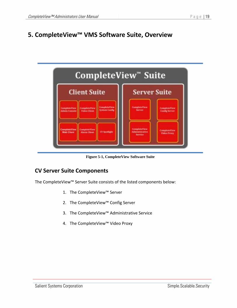
CompleteView™ Administrators User Manual P a g e | 19
Salient Systems Corporation Simple.Scalable.Security
5. CompleteView™ VMS Software Suite, Overview
CV Server Suite Components
The CompleteView™ Server Suite consists of the listed components below:
1. The CompleteView™ Server
2. The CompleteView™ Config Server
3. The CompleteView™ Administrative Service
4. The CompleteView™ Video Proxy
Figure 5-1, CompleteView Software Suite

CompleteView™ Administrators User Manual P a g e | 20
Salient Systems Corporation Simple.Scalable.Security
CompleteView™ Server is the core of the CompleteView software suite. CompleteView Server runs on the server hardware platform as a Microsoft® Windows® service, and is responsible for all aspects of video management including capture, storage, retrieval, analysis, and streaming.
CompleteView™ Config Server is a centralized database containing the viewing layouts for every user in an enterprise. In addition to the benefits offered by centralized storage and organization of these configurations, it also grants users the ability to roam to any computer in the enterprise on which the CompleteView Client is installed, while retaining individualized viewing layouts.
The CompleteView™ Administrator enables out‐of‐band management of the CompleteView Server system service. This application is required to remotely start and stop the CompleteView Server, and perform remote updates of the CompleteView software suite.
The Administrator application is installed automatically when the CompleteView Server component in the setup program is selected.
The CompleteView™ Video Proxy is a service that enables CompleteView™ Web Client users to view cameras and recorded video from multiple CompleteView servers in one interface. The Video Proxy acts as a single server location to which Web Client users can connect for CompleteView access.
CV Client Suite Components
The CompleteView™ Client Suite consists of the listed components below:
1. The CompleteView™ Video Client
2. The CompleteView™ Alarm Client
3. The CompleteView™ Web Client
4. CV Spotlight
5. The CompleteView™ Admin Console
6. The CompleteView™ System Configuration Utility

CompleteView™ Administrators User Manual P a g e | 21
Salient Systems Corporation Simple.Scalable.Security
The CompleteView™ Video Client is a Windows application installed on user workstations that offers users a simple yet powerful interface for performing complex video surveillance tasks.
Primary Features
Provide for the selection and viewing of live video and audio streams.
Organization of live video sources into an unlimited number of logically organized Viewing Layouts.
Display of camera locations on hyperlinked maps.
Searching among archived video for event recordings based upon the following criteria: server, camera, start‐date/time, end‐date/time and event type.
Smart Search performs searches on archived video to determine if motion has occurred at an earlier point in time. Smart Search accomplishes this by using video motion detection algorithms on previously recorded video events.
Time‐synchronized playback of video events from up to four video sources.
Exporting standardized video files to CD and DVD recordable optical discs.
Acquisition and export of still images as JPEG, uncompressed BMP or through evidence identification printouts.
Manipulation of PTZ controllable cameras.
The CompleteView™ Alarm Client is a black‐screen video client application. The user configures the application to monitor alarm events on one or more servers. Based upon user‐configurable monitoring schedules, live video will then be displayed when an alarm event occurs. The user can also quickly review the recorded video event in a side‐by‐side view with live video from the alarmed camera.
The CompleteView™ Web Client is a multi‐browser compatible web interface for CompleteView. CompleteView Web Client allows for live video display, Pan Tilt & Zoom, audio, and lighting control, as well as playback and exportation of recorded video from most Microsoft Silverlight™ compatible browsers without installing and managing a client software application.
CV SpotLight monitors alarm and motion events from selected cameras and displays video on event. CV SpotLight can be used standalone or in conjunction with other CompleteView Client applications. Used as a standalone client, the CV SpotLight provides a means of

CompleteView™ Administrators User Manual P a g e | 22
Salient Systems Corporation Simple.Scalable.Security
monitoring cameras without the need for a dedicated screen. Used with other CompleteView clients, the CV SpotLight adds pop up video alerts, and sound alerts on event to the CompleteView Video or Alarm Clients.
The CompleteView™ Admin Console is a Windows application that gives the administrator a tool to monitor the overall health, individual camera status, video archive usage and status, and other elements of every CompleteView server in the enterprise. This tool is also used to perform individual or group updates of the CompleteView software suite on selected servers. In version 46, multiple servers can be configured within one Console session. The servers appear as separate nodes in the left hand pane as they are opened.
In order to monitor a server, it must be running version 2.0 or later of the CompleteView Server application. In addition, to perform remote software updates or control the running state of the service, the CompleteView Administrative Service must be installed and operational.
The CompleteView™ System Configuration is a Windows application that allows administrators to configure every aspect of the video management system.
When used in conjunction with the CompleteView Config Server and the CompleteView Admin Console, the administrator can perform true single‐seat administration of virtually every aspect of the video surveillance infrastructure.

CompleteView™ Administrators User Manual P a g e | 23
Salient Systems Corporation Simple.Scalable.Security
6. Microsoft® Windows® Integration
The CompleteView™ video management system fully integrates with Microsoft® Windows® operating systems and networking technologies.
The CompleteView™ system is available in both 32‐bit and 64‐bit versions. See Section 2, “System Requirements,” for compatibility and system requirements.
CompleteView™ client and utility programs are Windows® applications that run in the foreground, and incorporate a Graphical User Interface (GUI) to provide user interaction with the system.
CompleteView™ server programs are Windows® system services that run in the background, do not incorporate a GUI, and whose primary purpose is to service requests from client and utility programs.

CompleteView™ Administrators User Manual P a g e | 24
Salient Systems Corporation Simple.Scalable.Security
CompleteView™ Windows® Applications
CompleteView™ client and administrative programs run in the foreground as Microsoft® Windows® applications.
Client and administrative programs provide a graphical user interface that enable the user to access and interact with VMS system resources and services.
CompleteView™ Windows® Applications
Icon Name Type Description
System
Configuration
System Configuration
Utility Enables configuration of all system elements.
Admin Console
Admin Console
Utility
Provides status & health monitoring for all critical system elements and events
Server GUI
Server GUI Utility Provides status & health monitoring for cameras configured on a single‐server.
Video Client
Video Client VMS Client Provides dedicated video and audio monitoring, playback and control.
Alarm Client
Alarm Client VMS Client Provides scheduled alarm‐driven video monitoring, playback and control.
CV Spotlight
CV Spotlight VMS Client Provides alarm‐driven video monitoring, playback and control.
CV Web Client
CV Web Client VMS Client Provides browser‐based live/recorded video display, export, and camera control.
Table 6‐1, CompleteView Applications

CompleteView™ Administrators User Manual P a g e | 25
Salient Systems Corporation Simple.Scalable.Security
CompleteView™, Windows® System Services
CompleteView™ server components run in the background as Windows® System Services. Generally, services provide core operating system features, such as Web serving, event logging, file serving, help and support, printing, cryptography, and error reporting. Services do not incorporate a GUI, and load automatically as part of application or operating system startup processes.
During installation, CompleteView™ automatically configures server services to start automatically as part of the operating system startup process. Their primary purpose is to service requests received via the Windows® TCP/IP service from CompleteView client and utility programs.
Services do not incorporate an application GUI, but they do have a set of properties that are configurable from the Services Snap‐in in the Windows® Computer Management Console.
CompleteView™ Windows® System Services
Icon Description
CompleteView Server
CompleteView main server
CompleteView Administrative Service
Provides main server remote control and remote software updates.
CompleteView
Configuration Server
User viewing layout profile, central database.
CompleteView Video Proxy
Permits CompleteView Web Client users to view cameras from multiple CompleteView™ servers in one interface. The Video Proxy acts as a single server location to which Web Client users can connect for CompleteView™ access.
Table 6‐2, CompleteView System Services

CompleteView™ Administrators User Manual P a g e | 26
Salient Systems Corporation Simple.Scalable.Security
From the Computer Management Console:
1. Start and stop CompleteView™ services.
2. Modify service properties.
Accessing CompleteView™ Windows® System Services
CompleteView™ server service properties can be viewed controlled and modified using the Services Snap‐in in the Windows® Computer Management Console.
From the Computer Management Console Services Snap‐in:
1. Start and stop CompleteView™ services.
2. Modify service properties.
To start Computer Management on the local computer:
Windows XP, Windows Server 2003:
Click Start, and select Control Panel. Click Performance and Maintenance, click Administrative Tools, and then double‐click Computer Management.
Windows 7, Windows 8, Windows Server 2008:
Click Start, and select Control Panel. Click System and Security, click Administrative Tools, and then double‐click Computer Management.
The Computer Management console for the local computer is displayed.
The Computer Management console consists of a window divided into three panes. The left pane contains the console tree, the middle pane contains details, and the right pane contains an action tree related to the item currently selected in the console tree.
“Computer Management (Local)" is displayed at the root of the console tree.

CompleteView™ Administrators User Manual P a g e | 27
Salient Systems Corporation Simple.Scalable.Security
When an item in the console tree is clicked, information about that item is displayed in the details pane. The information displayed is specific to the item selected in the console tree. In the console tree, expand System Tools, Storage, or Services and Applications to view the tools and services in each of these containers.
To access CompleteView™ services in the Computer Management Console:
1. In the console tree, expand Services and Applications then click Services.
2. The details pane will display a list of all currently installed system services and status information for each service. The Actions pane will display the action tree related to the currently selected service.
3. To select a service, double‐click the target service in the details pane.
For example, double‐click CompleteView™ Server. A properties dialogue box for the selected service will appear.
Service Properties Dialogue
Start>Control Panel>System and Security>Computer Management>Services>CompleteView Server

CompleteView™ Administrators User Manual P a g e | 28
Salient Systems Corporation Simple.Scalable.Security
Click [OK] to effect changes
Figure 6‐1, Service Properties Dialogue
The Service Properties dialogue <General> tab enables the System Administrator to manually stop or start a service and to configure the service startup type.
The Service Properties dialogue <Log On> tab allows the System Administrator to specify the service log on account. The service log on account determines service access permission to resources and objects on the operating system.
The Service Properties dialogue <Recovery> tab allows the System Administrator to specify how the service will behave in the event of a failure.
The Service Properties dialogue <Dependencies> tab lists the service dependencies. The present service will fail to run if a service it depends on is not running and a dependent service will fail if the present service is not running.
Typically, Windows® system services are configured as automatic, manual, or disabled:
An automatic service starts automatically when the operating system starts.
A service can be started manually by using the Computer Management Console, Services snap‐in.
A manual service can also be started by a related operating system service, a system device driver, or an action in the user interface that depends on the manual service.
A disabled service cannot be started automatically or manually. To start a disabled service, select an appropriate startup type.
By default, CompleteView™ server services are configured as automatic, having local system account permissions.

CompleteView™ Administrators User Manual P a g e | 29
Salient Systems Corporation Simple.Scalable.Security
Default Settings for CompleteView™ Services
Product Startup Type Log on as
CompleteView Server
Automatic Local system account
CompleteView Administrative Service
Automatic Local system account
CompleteView
Configuration Server
Automatic Local system account
CompleteView Video Proxy
Automatic Local system account
Table 6‐3, CompleteView Services Default Settings
Modifying CompleteView™ Services, default settings can cause VMS system malfunction.

CompleteView™ Administrators User Manual P a g e | 30
Salient Systems Corporation Simple.Scalable.Security
CompleteView™, Active Directory® Connector
CompleteView™ systems deployed on a Microsoft® domain network can be integrated with the network Active Directory (AD) directory service in order to simplify user/group management, and to facilitate user authentication.
Microsoft® Active Directory is a distributed directory service that enables secure, centralized management of the entire network. AD is a central repository of information and integrated services that provide the means to manage network resources including users, services, and devices. AD is installed on a Windows® network server that is configured for the Domain Controller (DC) role.
AD Authentication
Figure 6‐2, Active Directory Authentication

CompleteView™ Administrators User Manual P a g e | 31
Salient Systems Corporation Simple.Scalable.Security
The CompleteView™ Active Directory® Connector allows the System Administrator to define CompleteView™ users, groups, and permissions as part of the Windows® domain controller Active Directory users/groups schema. In this way, Active Directory® Connector eliminates the need to manually maintain identical user/group configurations across multiple CompleteView™ servers in a system. User/group configurations are maintained in a central location as part of the AD schema, and user authentication is performed by CompleteView™ servers against user credentials stored in the network Domain Controller Active Directory.
When implemented, an Active Directory® Connector can only be deployed within a single domain.
When using Active Directory® Connector, all CompleteView™ workstation and server computers must be members of the domain.
Active Directory integration is a feature of CompleteView™ Enterprise edition only.
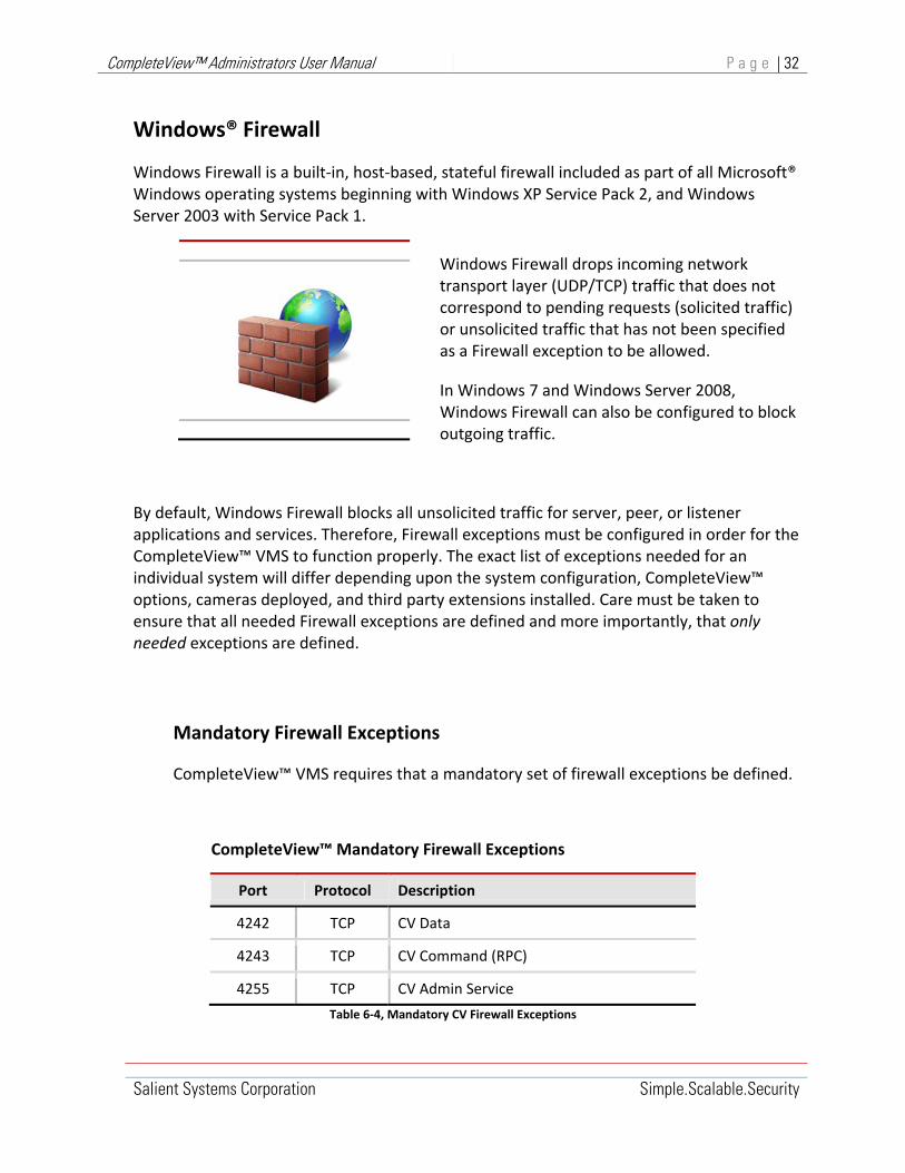
CompleteView™ Administrators User Manual P a g e | 32
Salient Systems Corporation Simple.Scalable.Security
Windows® Firewall
Windows Firewall is a built‐in, host‐based, stateful firewall included as part of all Microsoft® Windows operating systems beginning with Windows XP Service Pack 2, and Windows Server 2003 with Service Pack 1.
Windows Firewall drops incoming network transport layer (UDP/TCP) traffic that does not correspond to pending requests (solicited traffic) or unsolicited traffic that has not been specified as a Firewall exception to be allowed.
In Windows 7 and Windows Server 2008, Windows Firewall can also be configured to block outgoing traffic.
By default, Windows Firewall blocks all unsolicited traffic for server, peer, or listener applications and services. Therefore, Firewall exceptions must be configured in order for the CompleteView™ VMS to function properly. The exact list of exceptions needed for an individual system will differ depending upon the system configuration, CompleteView™ options, cameras deployed, and third party extensions installed. Care must be taken to ensure that all needed Firewall exceptions are defined and more importantly, that only needed exceptions are defined.
Mandatory Firewall Exceptions
CompleteView™ VMS requires that a mandatory set of firewall exceptions be defined.
CompleteView™ Mandatory Firewall Exceptions
Port Protocol Description
4242 TCP CV Data
4243 TCP CV Command (RPC)
4255 TCP CV Admin Service
Table 6‐4, Mandatory CV Firewall Exceptions

CompleteView™ Administrators User Manual P a g e | 33
Salient Systems Corporation Simple.Scalable.Security
Optional Firewall Exceptions
Depending upon system configuration, additional CV firewall exceptions may be required.
CompleteView™ Optional Firewall Exceptions
Port Protocol Description
4250 TCP CV Config Service
4502‐4534
TCP CV Web Client
8080 TCP CV Web Service
25 SMTP CV Email Notifications
Table 6‐5, Optional CV Firewall Exceptions
Camera Firewall Exceptions
Additional firewall exceptions are required in order to enable communication with all cameras in the system. These will vary according to the manufacturer and model of specific cameras. Some common ports used by camera protocols are listed below. For specific details about individual cameras, refer to the camera manufacturer documentation.
Common Camera Firewall Exceptions
Port Protocol Description
554 TCP Real Time Streaming Protocol (RTSP)
554 UDP Real Time Streaming Protocol, Unreliable (RTSPU)
6970‐7225 UDP RTP/RTCP session pool (generic stream implementation)
Table 6‐6, Common Camera Firewall Exceptions

CompleteView™ Administrators User Manual P a g e | 34
Salient Systems Corporation Simple.Scalable.Security
Alarm Device and Other Exceptions
Networked alarm devices and other third party extensions to the CompleteView™ VMS may also require Firewall Exceptions in order to communicate with the CompleteView™ system. For specific details about individual devices, refer to the documentation provided by the device manufacturer.
For specific details about integrating a third‐party product with CompleteView®, refer to the relevant product Integration Guide.
About Configuring Windows Firewall Exceptions
In order for CompleteView™ to function properly, firewall exceptions must be configured on individual servers and workstations connected to the network.
Firewall policy and firewall configuration on individual machines is integral to network‐wide security, as well as essential to application operability.
In a Windows® domain network, best practice urges that firewall configurations for domain members (individual server and workstation computers) be implemented through Active Directory Group Policy Objects (GPO). In this way, firewall configurations are centrally managed and automatically distributed to each domain member every time it establishes a network session.
For detailed information about Firewall and IPsec Policy deployments in Windows® Networks, refer to “Windows Firewall and IPsec Policy Deployment Step‐by‐Step Guide” http://technet.microsoft.com/en‐us/library/cc732400.aspx, Microsoft® online resource.
For complete information about Windows Firewall technologies, refer to “Network and Access Technologies, Windows Firewall” http://technet.microsoft.com/en‐us/network/bb545423.aspx, Microsoft® online resource.
In some instances, it may be desirable to manually configure the host‐based Windows® Firewall on each machine.
In Windows® XP, individual firewalls are configured by accessing Firewall from the Windows Security Center.
In Windows® Server 2003, individual firewalls are configured by accessing Firewall from the Windows® Control Panel.
In Windows® 7, Server 2008 and Server 2012 individual firewalls are configured by defining local firewall policy rules via the “Windows Firewall with Advanced Security”, MMC snap‐in.

CompleteView™ Administrators User Manual P a g e | 35
Salient Systems Corporation Simple.Scalable.Security
Configure Firewall Exceptions
This procedure creates individual firewall exceptions for all CompleteView™ mandatory ports and any needed optional ports.
Applies to Windows® XP and Windows® Server 2003.
Start Windows Firewall:
Windows® Server 2003:
1. Click Start, point to Control Panel, and then click Windows Firewall.
Windows® XP:
1. Click Start, click Control Panel, click Security Center then click Windows Firewall.
2. Click the Windows Firewall <Exceptions> tab
3. Click [Add Port]. The Add a Port dialogue will appear.
4. Enter the CompleteView™ port number and application name, click [OK].
5. Repeat step 3 and 4 for each CompleteView™ mandatory port and any needed optional port.

CompleteView™ Administrators User Manual P a g e | 36
Salient Systems Corporation Simple.Scalable.Security
Start>Control Panel>{Security Center}>Windows Firewall><Exceptions>
Click [Add Port] Enter {Port number} and {Name}, click [OK]
Add Exception for each required port
Figure 6‐3, Configure Firewall Exception
Configure Windows® Firewall with Advanced Security
This procedure uses the Firewall with Advanced Security MMC snap‐in to create a single firewall policy rule that permits all CompleteView™ communications.
Applies to Windows® 7, Windows® Server 2008 and Windows® Server 2008 (R2)
Start the Firewall with Advanced Security MMC snap‐in:
Windows® 7 or Windows® Server 2008 (R2):
1. Click Start, click Control Panel, in Control Panel, click System and Security.
2. Click Administrative Tools at the bottom of the screen.

CompleteView™ Administrators User Manual P a g e | 37
Salient Systems Corporation Simple.Scalable.Security
3. Double‐click Windows Firewall with Advanced Security, the Firewall with Advanced Security MMC snap‐in will appear. See Error! Reference source not found..
Windows® Server 2008: Windows® Server 2008:
1. Click Start, click Control Panel, in Control Panel click System and Maintenance.
2. Click Administrative Tools at the bottom of the screen.
3. Double‐click Windows Firewall with Advanced Security, the Firewall with Advanced Security MMC snap‐in will appear. See Error! Reference source not found..
4. In the Firewall with Advanced Security Console Tree, select Inbound Rules. 4. In the Firewall with Advanced Security Console Tree, select Inbound Rules.
5. In the Firewall with Advanced Security Actions Pane, click New Rule. The New Inbound Rule Wizard will appear.
6. Complete the New Inbound Rule Wizard, Step‐1 through Step‐5. See Table 6‐7 through Table 6‐9.

CompleteView™ Administrators User Manual P a g e | 38
Salient Systems Corporation Simple.Scalable.Security
New Inbound Rule Wizard
Step‐1
Rule Type
Select Port to apply rule to inbound traffic on specified CompleteView™ ports.
Select Port, Click [Next]
Step‐2
Protocol and Ports
Select TCP to apply rule only to inbound TCP protocol traffic on specified CompleteView™ ports.
Specify Completeview™ ports where:
4242 = CV Data 4243 = CV Command 4250 = CV Config Server 4255 = CV Admin Service 4502‐4534 = CV Web Server
Select {TCP}, Specify {local ports}, Click [Next]
Table 6‐7, Inbound Rule Wizard Steps 1 & 2

CompleteView™ Administrators User Manual P a g e | 39
Salient Systems Corporation Simple.Scalable.Security
New Inbound Rule Wizard
Step‐3
Action
Select Allow the connection to permit specified traffic on specified ports.
Select Allow the connection, Click [Next]
Step‐4
Profile
Select Domain or Private as appropriate for the network configuration.
Select Domain or Private, Click [Next]
Table 6‐8, Inbound Rule Wizard Steps 3 & 4

CompleteView™ Administrators User Manual P a g e | 40
Salient Systems Corporation Simple.Scalable.Security
New Inbound Rule Wizard
Name
Enter a Name and optional Description for the rule.
Click [Finish].
Enter {Name}, Click [Finish]
Table 6‐9, Inbound Rule Wizard Step 5

CompleteView™ Administrators User Manual P a g e | 41
Salient Systems Corporation Simple.Scalable.Security
Firewall with advanced security snap‐in
Actions Pane, Click New Rule
Figure 6‐4, MS Firewall with advanced security snap‐in

CompleteView™ Administrators User Manual P a g e | 42
Salient Systems Corporation Simple.Scalable.Security
7. Connecting To CompleteView™ Servers
In order to perform system configuration and maintenance tasks, it is necessary for the System Administrator to connect to and interact with CompleteView server processes. Server processes run as Microsoft® Windows® system services, and therefore do not incorporate a native Graphical User Interface (GUI). The CompleteView VMS includes utility programs that incorporate a GUI and communicate with server processes via Windows® native TCP/IP interfaces, thereby enabling system configuration and maintenance.
Figure 7‐1, Server Management Connections
Utility programs connect to server processes via the standard TCP/IP network services provided by Microsoft® operating systems. Utility programs may address server processes running on the local machine (the same computer), or they may address server processes running on remote computers.

CompleteView™ Administrators User Manual P a g e | 43
Salient Systems Corporation Simple.Scalable.Security
Server processes running on the local machine are addressed using the localhost loopback address.
Briefly:
Localhost is a name that translates to a loopback IP address.
Internet standards dictate that loopback IP addresses must fall within the address block 127.0.0.0/8. Refer to IETF “Request for Comments (RFC) 5735” for details.
Most commercial TCP/IP protocol stack implementations resolve the name localhost to the IP address 127.0.0.1. IP address 127.0.0.1 is the de facto standard localhost address.
Microsoft® Windows® operating systems incorporate a TCP/IP protocol stack that by default translates the localhost name to IP address 127.0.0.1.
Figure 7‐2, Client Server Transmit Datagram Flow

CompleteView™ Administrators User Manual P a g e | 44
Salient Systems Corporation Simple.Scalable.Security
All communications between CompleteView™ utility programs and server services are accomplished through the Microsoft® Windows® TCP/IP network service. It is a function of the network service to examine all datagram destination addresses and determine if individual datagrams are to be forwarded to the LAN, or looped back to the local machine. When a datagram is looped back, it is treated by the network service just as if received from the LAN. In this way, there is no distinction to the CompleteView™ software between loopback datagrams and datagrams received from across the network. The Windows® TCP/IP interface makes such communication details completely transparent to CompleteView™ client and server processes.
In order to connect with CompleteView™ servers anywhere in the network, a System Administrator need only know the target server IP address and have valid credentials for an administrator user account on that server. If localhost or any other loopback address is specified, the Windows® network service automatically establishes loopback connections.

CompleteView™ Administrators User Manual P a g e | 45
Salient Systems Corporation Simple.Scalable.Security
Connect To Server Dialog
CompleteView™ utility programs routinely connect with CompleteView™ servers as part of the configuration and maintenance tasks they perform. Whenever a utility program establishes its connection to a server, the System Administrator or User will be prompted with a Connect to Server dialogue box.
In the Connect to Server dialogue box, input the requested information as follows:
Address Field ‐ input the IP address of the target server. The name localhost may be used.
Username Field ‐ input the valid username for an administrator account on the target server. The default username for localhost connections is admin.
Password Field ‐ input the valid password for an administrator account on the target server. The default password for localhost connections is <blank>.
Figure 7‐3, Connect To Server Dialogue
Connect To Server
<‐ Target server IP address
<‐Target server account Username
<‐Target server account Password
Click [OK] to logon

CompleteView™ Administrators User Manual P a g e | 46
Salient Systems Corporation Simple.Scalable.Security
CompleteView™ Utility Programs
CompleteView™ utility programs provide the System Administrator with a graphical user interface and the means to interact with server services in order to configure, maintain and monitor CompleteView™ systems.
Utility Programs
Icon Program Description
System
Configuration
System Configuration Tool
Enables configuration of all system elements, user accounts and user‐specific viewing layouts on CompleteView™ servers and video clients
Admin Console
Admin Console
Provides status & health monitoring for all critical system elements and events.
Provides user indications, logging and email alerts for system events and fault conditions.
Supports server software updates.
Server GUI
Server GUI
Automatically installed along with each CompleteView™ server .
Provides status & health monitoring for cameras configured to the attendant server.
Provides user indications and logging for events and fault conditions.
Table 7‐1, CompleteView Utility Programs

CompleteView™ Administrators User Manual P a g e | 47
Salient Systems Corporation Simple.Scalable.Security
8. CompleteView™ License Management
CompleteView™ systems are licensed on a per camera basis.
In a deployed system, the CompleteView™ licensing schema requires camera licenses to be allocated among CompleteView™ servers.
Each server is provisioned with a License Key.
Every License Key incorporates a set of Feature Keys.
The Feature Keys within a License Key enable the set of cameras allocated to that server.
The Feature Keys within an individual server License Key also enable any other VMS capabilities or features allocated to that server.
Typically, all servers in a system incorporate a uniform set of capabilities and features, but each manages a different group of cameras
In a system that employs a single server as shown in Figure 8‐1 below, all cameras and features are maintained in a single License Key located at the server.
Figure 8‐1, Single Server License Model

CompleteView™ Administrators User Manual P a g e | 48
Salient Systems Corporation Simple.Scalable.Security
When properly configured, the server configuration agrees with the set of cameras and features contained in the License Key, and all client configurations agree with the server configuration.
In a system that employs multiple servers as shown in Figure 8‐2 below, the cameras and features included in the system are maintained in multiple license keys where one license key is allocated per server.
Figure 8‐2, Multi‐Server License Model
In this scenario, for each server, the set of cameras and features contained in its License Key agrees with its own configuration. In addition, client configurations must agree with the sum of server configurations.
In a multiple server system, all servers should incorporate the same set of VMS features, but each will manage a different set of cameras.
IP Camera Feature Keys can be moved between servers.

CompleteView™ Administrators User Manual P a g e | 49
Salient Systems Corporation Simple.Scalable.Security
CompleteView™ License keys
Every server in a CompleteView™ VMS System must be provisioned with a License Key. The server License Key includes Feature Keys for IP Cameras managed by that server, as well as Feature Keys to enable system‐wide functionality common to all servers in the system.
CompleteView Server software License and Feature Keys are stored in an encrypted format and distributed as either a ‘Hardware’ or ‘Software’ key.
CompleteView Server v2.0 and v3.x installations require a hardware license key.
CompleteView v4.x and later use a software license key.
Hardware License Keys are distributed in the form of a USB dongle that must be attached to each computer where the CompleteView Server software has been installed.
Software License Keys are distributed in the form of a license file named “cvserver.lic.” The cvserver.lic file must be located in the CompleteView™ installation directory on each server in the system.
Obtaining a Hardware License Key
Hardware License Keys are delivered along with the CompleteView™ software installation disks.
Simply insert the hardware License dongle into any unused USB port prior to installing the CompleteView™ Server Software.
Obtaining a Software License Key
Prior to version 4.5.1, software License Keys are obtained from Salient Systems after CompleteView™ server software installation. In CompleteView v4.6 and later, software license keys are generated at the time of installation, are private, and cannot be transferred from one server to another.
Prior to server software installation, an email should be received from [email protected] .
To obtain a software License key:
1. Install the CompleteView™ server software. This will generate a “Globally Unique Identifier” (GUID) for the server installation.
2. Retrieve the server GUID.

CompleteView™ Administrators User Manual P a g e | 50
Salient Systems Corporation Simple.Scalable.Security
3. Reply to [email protected] with the server GUID. [email protected] will respond with an email having the file ‘cvserver.lic’ attached.
4. Receive the “cvserver.lic” license file from [email protected] .
5. Save or copy the “cvserver.lic” license file to the CompleteView installation directory.
Retrieving the Server Product ID
The server Product ID is essential to generating server Licenses and Feature Keys.
Once a server software installation is complete, the server GUID can be accessed using the CompleteView Configuration Utility.
Connect to the target server:
1. Start the System Configuration Utility. Click Start and then click All Programs. Next click CompleteView, double‐click System Configuration. The configuration utility Select Task dialogue will appear.
2. Click [Configure Servers]. A Connect To Server dialogue will appear.
3. Input the IP address and valid credentials for an administrator account on that server. The localhost address and default account credentials may be used. Click [OK]. The CompleteView Server Configuration Console will appear.
4. In the Server Configurations console tree, mouse over and select the target server container. The details pane of the Server Configuration Console will display a set of tabbed windows. Select the General tab.
5. Click [Feature Keys]. A ‘License Not Found’ dialog will appear.

CompleteView™ Administrators User Manual P a g e | 51
Salient Systems Corporation Simple.Scalable.Security
License Not Found
Start>All Programs>CompleteView>System Configuration>{selected server}>General>[Feature Keys]
The Product ID is displayed in the dialogue text box, click [Close]
Figure 8‐3 License Not Found Dialogue

CompleteView™ Administrators User Manual P a g e | 52
Salient Systems Corporation Simple.Scalable.Security
Managing Feature Keys
Once a CompleteView™ system is operational, server License Keys may be modified by adding and removing Feature Keys, or by moving Feature Keys between servers. License keys will need to be modified in order to support system reconfiguration and upgrades.
Most often, License Keys are modified in order to add IP cameras to the system, remove IP cameras from the system, or, to move IP cameras between servers.
Accessing Feature Keys and Product ID
Every CompleteView server is provisioned with a License Key. Every License Key includes a Product ID that uniquely identifies the server installation and contains a set of Feature Keys.
Once a server software installation is complete and licensed, the server Product ID and Feature Keys are accessed using the CompleteView Configuration Utility.
On the server computer where CompleteView™ is installed and licensed:
1. Start the System Configuration Utility; click [Configure Servers].
2. Logon to the LocalHost server
3. Navigate to the <General> tab
4. Click [Feature Keys]. A Feature Keys dialog box will appear.
Figure 8‐4 Feature Keys Dialogue

CompleteView™ Administrators User Manual P a g e | 53
Salient Systems Corporation Simple.Scalable.Security
The Product ID is displayed in a shaded text box in the upper portion of the Feature Keys dialogue. The Product ID can be highlighted and copied, but not modified.
The license Feature Keys are displayed in a scroll box in the lower portion of the Feature Keys dialogue. Feature Keys can be selected with a mouse click. Once selected, Feature keys can be modified using the [Add], [Remove] or [Move] buttons beneath the Feature Key scroll box.

CompleteView™ Administrators User Manual P a g e | 54
Salient Systems Corporation Simple.Scalable.Security
STEP‐1
Start>All Programs>CompleteView>System Configuration
Start the System Configuration Utility, select Configure Servers button
STEP‐2
…>CompleteView>System Configuration>Server Configuration
Log onto the localhost server
STEP‐3
…>CompleteView>System Configuration>Server Configuration>General
Select [Feature Keys] button
Result
…>CompleteView>System Configuration>Server Configuration>General>Feature Keys
Access Product ID and Feature Keys
Figure 8-5 Access Feature keys

CompleteView™ Administrators User Manual P a g e | 55
Salient Systems Corporation Simple.Scalable.Security
Adding Feature Keys
To add a Feature Key, navigate to the Feature Keys Dialogue box. (See section 0)
1. In the Feature Keys dialogue, click [Add]. The Add Feature Key dialogue will appear.
2. In the Add Feature Key dialogue, input the Feature Key & Validation Code if required, click [OK].
STEP‐1 STEP‐2
Start>All Programs>CompleteView>System Configuration>Server Configuration>General>[Feature Keys]
Access the Feature Keys dialogue click [Add] Input Feature Key information click [OK]
The Add Feature Key validation code is only required when moving feature keys between servers. New feature keys can be added to servers without a validation code.

CompleteView™ Administrators User Manual P a g e | 56
Salient Systems Corporation Simple.Scalable.Security
Removing Feature Keys
To remove a Feature Key, access the Feature Keys Dialogue box. (See section 0)
1. In the Feature Keys dialogue, select the Feature Key to be removed. Click [Remove].
2. In the Question dialogue, click [Yes] or [No].
STEP-1 STEP-2
Start>All Programs>CompleteView>System Configuration>Server Configuration>General>[Feature Keys]
Select Feature Key to be removed, click [Remove]
Click [Yes] or [No]
Removing Feature Keys from a server License Key removes functionality from the server. The impact on the system configuration must be understood prior to modifying a server license or removing any feature key.

CompleteView™ Administrators User Manual P a g e | 57
Salient Systems Corporation Simple.Scalable.Security
Moving Camera Feature Keys
CompleteView™ systems are licensed on a per camera basis.
In a deployed system, the CompleteView™ licensing schema requires camera licenses to be allocated among CompleteView™ servers. At times, it may become necessary to re‐allocate the IP cameras in a system. To do so requires removing camera licenses from a source server and then adding them to a destination server.
Camera licenses are contained in Camera Feature Keys found in the CompleteView™ License Key provisioned at each server.
Moving Camera Licenses involves a process of removing Camera Licenses from the IP Camera Feature Key at a source server and then adding those IP Camera Licenses to the IP Camera Feature Key to a server license key.
Moving Camera Feature Keys between Software License Keys
To move camera licenses between servers provisioned with software license keys contact Salient Systems Customer Support:
Customer Support
Address: 10801 N. MoPac Expressway Building 3, Suite 700 Austin, TX 78759
Phone: 512‐617‐4802
Email: [email protected]

CompleteView™ Administrators User Manual P a g e | 58
Salient Systems Corporation Simple.Scalable.Security
9. Software Installation
CompleteView™ Installation Wizard
To install the CompleteView™ server software:
1. Insert the CompleteView installation CD into the CD‐DVD/ROM drive, and allow the CompleteView™ installer to run automatically,
‐OR‐
2. In the CompleteView™ installation CD root directory, double‐click the program file setup.exe.
The CompleteView™ Setup Wizard will launch.
Follow the instructions on the Welcome Dialogue screen and then click [Next] to continue. The User Information dialogue box will appear.
INSTALLATION WIZARD STEP - 1
Welcome Dialogue
Click [Next] to continue

CompleteView™ Administrators User Manual P a g e | 59
Salient Systems Corporation Simple.Scalable.Security
INSTALLATION WIZARD STEP - 2
User Information
Click [Next] to continue
In the User Information dialogue box, enter the Name and Company information into the fields provided. Click [Next] to continue.
The Select Packages screen will appear.

CompleteView™ Administrators User Manual P a g e | 60
Salient Systems Corporation Simple.Scalable.Security
INSTALLATION WIZARD STEP ‐3
Select Packages
Select applications to install, then click [Next] to continue
The Select Packages dialogue determines which CompleteView™ applications will be installed.
Any combination of Client and Server applications may be selected. Features should be selected based on the computer’s intended role.
To setup a client workstation, select options under the Client Applications section.
To configure a CompleteView server, select Server Application options.
Click Next to continue, the Installation Folder dialogue box will appear.

CompleteView™ Administrators User Manual P a g e | 61
Salient Systems Corporation Simple.Scalable.Security
INSTALLATION WIZARD STEP ‐4
Installation Folder
Click [Next] to continue
The Installation Folder dialogue determines where CompleteView™ components will be installed. By default, CompleteView is installed in C:\Program Files\CompleteView.
1. Specify the CompleteView™ installation folder.
2. Verify that the amount of available disk space exceeds the amount of disk Space required.
3. Click [Next] to continue, the Shutting Down Applications dialogue will appear.

CompleteView™ Administrators User Manual P a g e | 62
Salient Systems Corporation Simple.Scalable.Security
INSTALLATION WIZARD STEP ‐5
Shutting Down Applications
Click [Next] to continue
The CompleteView™ Installation Wizard inspects the host system for installed and running CompleteView™ components. When discovered, running components are shut down and stopped as required.
When the Shutting Down Applications process is complete, click [Next] to continue.
The Shortcut Folder dialogue will appear.

CompleteView™ Administrators User Manual P a g e | 63
Salient Systems Corporation Simple.Scalable.Security
INSTALLATION WIZARD STEP -6
Shortcut Folder
Click [Next] to continue
Use the Shortcut Folder dialogue to specify the Windows® Start Menu folder where CompleteView™ shortcut icons will be placed during installation.
1. Specify a CompleteView™ shortcut folder.
2. Click [Next] to continue.
The Ready to Install dialogue will appear.

CompleteView™ Administrators User Manual P a g e | 64
Salient Systems Corporation Simple.Scalable.Security
INSTALLATION WIZARD STEP ‐7
Ready To Install
Click [Next] to continue
The Ready To Install dialogue displays the user‐selected options that will be used to install CompleteView™.
1. Inspect and verify the selected installation options.
2. If necessary, use the [Back] button to return to previous dialogues and make changes.
3. Click [Next] to continue.
The Installing CompleteView™ dialogue will appear.

CompleteView™ Administrators User Manual P a g e | 65
Salient Systems Corporation Simple.Scalable.Security
INSTALLATION WIZARD STEP -8
Installing CompleteView™
Click [Cancel] to abort installation
The Installing CompleteView™ dialogue consists of two progress bars that indicate installation progress.
The upper progress bar indicates the installation progress for the individual component currently being installed.
The lower progress bar indicates overall installation progress.
1. Click [Cancel] to abort the installation.
‐OR‐
2. When the installation is complete, click [Next] to proceed

CompleteView™ Administrators User Manual P a g e | 66
Salient Systems Corporation Simple.Scalable.Security
INSTALLATION WIZARD STEP -9
Device Driver Installation
Click [Next] to continue
The Device Driver Installation dialogue installs the driver software for CompleteView™ analog video capture cards.
To install analog drivers click the appropriate [Install] button.
When installing Gen I capture card drivers, refer to Section “Installing Gen I Capture Card Drivers.”
When installing Gen II capture card drivers, refer to Section “Installing Gen II Capture Card Drivers.”
Once the appropriate analog capture card drivers have been installed or, if there are no analog capture cards in the system, click [Next] to proceed.
The Installation Successful dialogue will appear.

CompleteView™ Administrators User Manual P a g e | 67
Salient Systems Corporation Simple.Scalable.Security
INSTALLATION WIZARD STEP -10
Installation Successful
Click [Reboot] to restart the computer
The installation process is now complete.
If no errors were encountered, click [Reboot] to restart the computer.

CompleteView™ Administrators User Manual P a g e | 68
Salient Systems Corporation Simple.Scalable.Security
Installing Gen I Capture Card Drivers
Select Your Video Standard
Select video format. Click [Next] to continue.
If the option to install Gen I capture card drivers was selected during Step‐9 of the CompleteView™ Installation Wizard, the Select Your Video Standard dialogue will appear.
In the Select Your Video Standard Dialogue window, select the video format appropriate for the installation. Installations in North America require the NTSC format.
Click [Next] to continue, the driver installation will begin.
During installation, Windows® may prompt for confirmation to install each driver, there will be two drivers installed for each video port. For each prompt please click “Continue Anyway.”

CompleteView™ Administrators User Manual P a g e | 69
Salient Systems Corporation Simple.Scalable.Security
Installing Gen II Capture Card Drivers
Windows Security
Click [Install]
If the option to install Gen II capture card drivers was selected during Step‐9 of the CompleteView™ installation wizard, the Windows Security dialogue will appear.
Click [Install] to permit Gen II driver installation.
Gen II Driver Installation
Installing Gen II Driver Click [OK] to continue
The Gen II capture card drivers install automatically.
During installation, the Installing Driver message box appears. Upon completion, the Driver Installed dialogue box appears. Click [OK] to complete installation.

CompleteView™ Administrators User Manual P a g e | 70
Salient Systems Corporation Simple.Scalable.Security
10. System Configuration
Configuring the CompleteView™ VMS involves setting parameters needed to establish proper relationships between system components, and configuration of system devices and their interfaces for proper operation.
Component Relationships
Video Server Managed Componenets Video Client Managed
Compomnents
Figure 10‐1, VMS System Component Relationships
In the CompleteView™ system, every physical component is represented by a companion Component (software) Object. Component Objects embody the particular attributes and parameters needed by each component for proper initialization and operation.
A system component and its attendant Component Object can relate to hardware devices such as cameras, system resources such as disk storage, application data such as View Layouts, or networked resources such as video servers etc.
In general, system components can be categorized as edge devices, server subsystem components, and client subsystem components.

CompleteView™ Administrators User Manual P a g e | 71
Salient Systems Corporation Simple.Scalable.Security
Component objects are contained in CompleteView™ configuration files. There are two types of configuration file:
Server configuration files contain the Component Objects relating to components that are accessed and managed by CompleteView™ servers.
Client configuration files contain the Component Objects relating to components that are accessed and managed by CompleteView™ clients.
There is one active configuration file for each CompleteView™ client, and one for each CompleteView™ server. Every server and every client relies on its configuration file for an understanding of what resources exist in a system, as well as how to access, communicate with, initialize, and manage those resources.
Thus, the CompleteView™ system is configured by creating an Object in the appropriate configuration file and ensuring proper settings for the object properties for each system component or resource.
System Components
Edge devices
Edge Devices include cameras as well as other devices that augment basic camera functionality.
The basic function of a camera is to provide a constant video stream to the Video Server. Basic camera functionality can be augmented by a variety of capabilities including:
PTZ control
Companion audio streams
Access control I/O
Alarm information
Edge Storage
The wide variety of cameras available from different manufacturers includes many that integrate various combinations of these capabilities. Others may include only
CompleteView™ Administrators User Manual P a g e | 72
Salient Systems Corporation Simple.Scalable.Security
basic camera functionality. Some of these capabilities are implemented as a part of stand‐alone I/O devices that attach independently to the network or server subsystem.
Edge Device components include:
Cameras
Audio Devices
Alarm Devices
Video client components
The CompleteView™ Video Client is responsible for presenting camera video to the end user.
Individual Video Clients access camera video from one or more CompleteView™ Servers.
The video client software enables camera video to be organized into custom View Layouts for presentation to the end‐user. A single View Layout can contain video from multiple cameras from multiple servers, as well as map images and web pages.
Views are associated with either users or locations. Views associated with a user may only be accessed by that user. Views associated with locations can be accessed by any user having sufficient permissions to access the location containing a View Layout.
In addition to View Layouts,
Video Client components include:
Servers
Users/Groups
Zones/Sites
Views
Maps
CompleteView™ Administrators User Manual P a g e | 73
Salient Systems Corporation Simple.Scalable.Security
The Video server components
The CompleteView™ video server is responsible for initializing and managing cameras, performing video recording, and serving live and recorded video to video clients.
To a Video Client, each Video Server represents a group of cameras, wherefrom each camera provides a unique video stream. Servers make live and recorded camera video accessible to Clients via server user/group accounts that convey access permissions and control priorities to client user/group accounts.
In the course of providing camera video to clients, the video server performs many functions related to ensuring the proper operation of cameras and related edge devices, video stream processing to provide advanced features, and video storage and retrieval.
Video Server components include:
Users/Groups
Cameras
Audio Devices
Alarm Devices
Serial Ports
Volumes
Schedules
Diagnostics/Reporting

CompleteView™ Administrators User Manual P a g e | 74
Salient Systems Corporation Simple.Scalable.Security
Configuration Files
CompleteView™ system configuration information is contained in configuration files located on each server and client computer. The configuration files provide to each client or server its own independent understanding of the available system resources and related configuration parameters.
By default, configuration files on each computer are located in the CompleteView™ installation directory.
The Server configuration file
Server Configuration File
C:\Program Files\CompleteView\ servercfg.cvw
Figure 10‐2, Server Configuration File

CompleteView™ Administrators User Manual P a g e | 75
Salient Systems Corporation Simple.Scalable.Security
The Client configuration file
Client Configuration File
C:\Program Files\CompleteView\ clientcfg.cvw

CompleteView™ Administrators User Manual P a g e | 76
Salient Systems, Inc. Simple.Scalable.Security
11. CompleteView™ Configuration Utility
The CompleteView™ Configuration utility provides the ability to configure and maintain Server and Client configuration files.
When started, the configuration utility opens or creates a configuration Session that accesses one or more client or server configuration files. The configuration utility presents information from configuration files graphically in a Windows® console. From the Windows® console, the System Administrator can easily view and edit server and client configuration settings.
When configuring servers, the configuration utility always accesses the servercfg.cvw file in the CompleteView installation directory on the specified server.
When configuring clients the System Administrator directs the Configuration Utility to access the current client configuration file on the local machine, a client configuration file stored on disk or in a network share, or a configuration file stored on a CompleteView™ Configuration Server.
Configuring the client on the local machine always accesses the clientcfg.cvw file in the CompleteView™ installation directory.
A client configuration file stored on disk, in a network share or on a CompleteView™ Configuration Server may take the form <anyname>.cfw where <anyname> can be any valid windows filename but must have a .cfw file extension.
Configuration Sessions
A Configuration session is defined as the configuration file or set of configuration files opened by an instance of the Configuration Utility.
A configuration Session starts whenever the Configuration Utility opens a client configuration file, a server configuration file, or a saved configuration session. Once started, the System Administrator can add or delete configuration files to the session as needed.
When the configuration activity is complete, the open session may be saved for later use or discarded upon exit.

CompleteView™ Administrators User Manual P a g e | 77
Salient Systems Corporation Simple.Scalable.Security
To start the Configuration Utility
1. Click Start, click All Programs, click to open the CompleteView folder, and then click System Configuration.
2. The CompleteView™ System Configuration, the Select Task dialogue will appear.
Start>All Programs>CompleteView>System Configuration>
Open an existing session enables the System Administrator to open a saved configuration Session file.
Configure Servers enables the System Administrator to create a server configuration Session.
Configure Clients enables the System Administrator to create a client configuration Session.
Exit exits the CompleteView™ System Configuration utility.

CompleteView™ Administrators User Manual P a g e | 78
Salient Systems Corporation Simple.Scalable.Security
To create a server configuration session
1. Click Start, click All Programs, click to open the CompleteView™ folder, and then click System Configuration.
2. The CompleteView™ System Configuration Select Task dialogue will appear.
3. In the Select Task dialogue, click Configure Servers. A Connect to Server dialogue appears.
Connect To Server
<‐ Target server IP address
<‐Target server account Username
<‐Target server account Password
Click [OK] to logon Figure 11‐1, Connect To Server Dialogue
4. In the Connect to Server dialogue box, input the requested information as follows:
Address Field ‐ input the IP address of the target server. The name localhost may be used.
Username Field ‐ input the valid username for an administrator account on the target server. The default username for localhost connections is admin.
Password Field ‐ input the valid password for an administrator account on the target server. The default password for localhost connections is <blank>.

CompleteView™ Administrators User Manual P a g e | 79
Salient Systems Corporation Simple.Scalable.Security
5. Click [OK] to logon. The server Configuration Console will appear. Refer to section 0 for detailed information on the Server Configuration Console.
To create a client configuration session
1. Click Start, click All Programs, click to open the CompleteView folder, and then click System Configuration.
2. The CompleteView™ System Configuration Select Task dialogue will appear.
3. In the Select Task dialogue, click Configure Clients. A Client Configuration dialogue will appear.
Client Configuration
Click [OK] to continue
Figure 11‐2, Client Configuration Dialogue
4. In the Client Configuration dialogue, specify the client configuration file to be opened by the configuration session being created, where:
Local Configuration creates a client configuration session using the clientcfg.cvw file in the CompleteView™ installation directory on the local machine.

CompleteView™ Administrators User Manual P a g e | 80
Salient Systems Corporation Simple.Scalable.Security
Configuration File creates a client configuration session using a client configuration file specified via a browse for file dialogue.
Configuration Server creates a client configuration session using a client configuration file retrieved from a CompleteView™ Configuration server.
5. Click [OK], a dialogue will appear as follows:
When creating a Local Configuration session, a Logon dialogue will appear. In the Logon dialogue, input valid user account credentials for the localhost client and click [OK].
When creating a Configuration File session, a browse for file dialogue will open. Using the browse for file dialogue, navigate to and select a client configuration file then click [Open].
When creating a Configuration Server session, a Client Configuration dialogue will appear. In the Client Configuration dialogue, input the IP address and valid user account credentials for the target configuration server and then click [OK].
6. A Client Configuration console will open containing the client configuration file as specified by steps 4 through 5, above.

CompleteView™ Administrators User Manual P a g e | 81
Salient Systems Corporation Simple.Scalable.Security
To open a saved configuration session
1. Click Start, click All Programs, click to open the CompleteView folder, and then click System Configuration.
2. The CompleteView™ System Configuration Select Task dialogue will appear.
3. In the Select Task dialogue, click Open an Existing Session. An Open Session File dialogue will appear.
4. Using the Open Session File dialogue, navigate to and select a client configuration file.
5. Click [Open]. A Client Configuration console opens containing the selected client configuration file.
Start>All Programs>CompleteView>System Configuration>Open Existing Configuration
Figure 11‐3, Open session File Dialogue

CompleteView™ Administrators User Manual P a g e | 82
Salient Systems Corporation Simple.Scalable.Security
Configuration Consoles
The CompleteView™ Configuration Utility includes two Configuration Consoles. These Configuration Consoles provide the user interface that facilitates editing CompleteView™ client and server configuration files.
The CompleteView™ Server Configuration console automatically opens whenever the configuration utility accesses a server configuration file.
The CompleteView™ Client Configuration console automatically opens whenever the configuration utility accesses a client configuration file.
Both configuration consoles consist of a System Menu, a Configuration Toolbar and a split‐window divided into two panes.
In the split window, the left pane contains the console tree and the right pane contains the details pane. Details are presented in a set of tabbed windows within the details pane. After clicking an item in the console tree, information about that item is displayed in the details pane. The information displayed is specific to the selected item.
The console tree presents an explorer view of the information contained in CompleteView™ configuration files.
Configuration, Nested Containers
Server Configuration Client Configuration
Users/Groups Zones/Sites
Cameras Users/Groups
Audio Devices Servers
Alarm Devices
Serial Ports
Volumes
Schedules
Table 11‐1, Configuration File Containers
At the Console Tree root‐level, there is one or more Configuration Containers. Each Configuration Container relates to a CompleteView™ client or sever configuration file. Nested within each Configuration Container is a set of component object containers.

CompleteView™ Administrators User Manual P a g e | 83
Salient Systems Corporation Simple.Scalable.Security
Nested component object containers relate to categories of information found in configuration files such as Cameras or Users.
Objects represent members within a category such as Camera1 within the Cameras container or, User3 within the Users/Groups container. Every object defined in a configuration file corresponds with an actual device, user or other system component. Each object contains the configuration settings needed by the CompleteView™ System in order to interface with and manage an objects’ corresponding component.
The Configuration Console System Menu and Toolbar provide the commands and functions needed to create, edit and manage Component Objects within configuration files, client and server configurations as well as Configuration Sessions.

CompleteView™ Administrators User Manual P a g e | 84
Salient Systems Corporation Simple.Scalable.Security
Server Configuration Console
The Server Configuration Console provides the user interface that facilitates editing CompleteView™ server configuration files.
Start>All Programs>CompleteView>System Configuration>Configure Servers
Figure 11‐4, Server Configuration Console
The server configuration console consists of:
A System Menu
A Configuration Toolbar
A split‐window divided into a Console Tree and a Details Pane
A Status Bar

CompleteView™ Administrators User Manual P a g e | 85
Salient Systems Corporation Simple.Scalable.Security
Server Configuration Console, System Menu
The server configuration Menu Bar contains four drop‐down menus that provide the commands and functions needed to manage server configuration sessions and to create, edit and manage server Component Objects within server configuration files.
The system Menu is organized into four drop‐down menus:
The File Menu
The Server Configuration Menu
The View Menu
The Help Menu
To access commands within a drop‐down menu, mouse over the menu of choice and select. The drop‐down menu will appear.
The File Menu provides commands to manage Configuration Sessions.
The Server Configuration Menu provides commands to create and edit server Component Objects.
The View Menu provides control over the Status Bar and Toolbar display.
The Help Menu can provide software revision information or open this manual.
Start>All Programs>CompleteView>System Configuration>Configure Servers
Table 11‐2, Server Configuration System Menu

CompleteView™ Administrators User Manual P a g e | 86
Salient Systems Corporation Simple.Scalable.Security
The Server Configuration Console, File Menu
The File Menu contains commands for managing server Configuration Sessions.
A server Configuration Session is the set of server configuration files and their content, opened simultaneously by an instance of the configuration console.
A Session is created whenever the server Configuration Console is directed to access a configuration file. Once created a session may be saved, re‐opened, modified and saved again.
File Menu
Start>All Programs>CompleteView>System Configuration>Configure Servers>File
New Session Creates a new, empty session.
Open Session Open a previously saved session.
Save Session Save the current session using the current filename.
Save Session As Save the current session using a different filename
Save and Exit Save the current session and quit the System Config utility.
Exit Quit the System Config utility.
New session causes the current session to be abandoned and an empty session to be created. The content of the current session is lost.
Open Session causes the current session to be abandoned and a enables the user to browse for and open a previously saved session. The content of the current session is lost.
Save Session saves the current session using the current filename.
Save Session as opens a browse to dialogue and enables the user to save the current session using a different filename.
Table 11‐3, File Menu

CompleteView™ Administrators User Manual P a g e | 87
Salient Systems Corporation Simple.Scalable.Security
Save and Exit saves the current session using the current filename and quits the server configuration console.
Exit quits the server configuration console without saving the current configuration.

CompleteView™ Administrators User Manual P a g e | 88
Salient Systems Corporation Simple.Scalable.Security
The Server Configuration Console, Configuration Menu
The Server Configuration Menu contains commands for managing server Configurations within the current session.
Each Server Configuration opened within the session represents a server configuration file accessed by the server configuration utility.
Server Configuration Menu
Start>All Programs>CompleteView>System Configuration>Configure Servers>Server Configuration
Figure 11‐5, Server Configuration Menu

CompleteView™ Administrators User Manual P a g e | 89
Salient Systems Corporation Simple.Scalable.Security
The Server Configuration Console, View Menu
The View Menu contains commands for customizing the configuration console display by enabling or disabling the Configuration Console toolbar and status display.
View Menu
Start>All Programs>CompleteView>System Configuration>Configure Servers>View
Toolbar Enables/disables the Server Configuration
Status Bar Enables/disables the Server Configuration
Table 11‐4, Server Configuration View Menu

CompleteView™ Administrators User Manual P a g e | 90
Salient Systems Corporation Simple.Scalable.Security
Server Configuration Console, Toolbar
The server configuration toolbar contains the most commonly used items displayed in the system menus.
The toolbar buttons are arranged in three groups corresponding to the File Menu functions and the Configuration Menu functions as well as a set of miscellaneous buttons.
File Menu Buttons Configuration Menu Buttons Misc Buttons Figure 11‐6, Server Configuration Toolbar
Server Configuration Console Toolbar, File Buttons
The Server Toolbar File buttons provide session management functions that correspond with the system File Menu.
Server Toolbar, File Buttons
Icon Description
New Session
Open a new, empty session.
Open Session
Open a saved session.
Save Session
Save the current session using the current filename.
Save the current session and quit the System Config utility.

CompleteView™ Administrators User Manual P a g e | 91
Salient Systems Corporation Simple.Scalable.Security
Server Toolbar Configuration Buttons
The Server Toolbar Configuration buttons provide functions for editing server configurations that correspond with the system Configuration Menu.
Server Toolbar, Configuration Buttons
Button Description
Add Configuration
Add a server configuration to the current session.
Save the current server configuration.
Add Group
Add a new Group container within the selected Users/Groups container.
Add User
Add a new User to the selected Users/Groups container or, to the selected Group within a Users/Groups container.
Add Camera
Add a new Camera object to the selected Cameras container.
Search Cameras
Find a Camera on the network.
Add QuickTrack
Create a new QuickTrack camera source.
Add Alarm Device
Add a new Alarm Device object to the selected Alarm Device container.
New Volume
Create a new Volume on disk and add it to the selected Volumes container.
Table 11‐5, Server Toolbar, File Buttons

CompleteView™ Administrators User Manual P a g e | 92
Salient Systems Corporation Simple.Scalable.Security
New Schedule
Add a new Schedule object to the selected Schedules container.
Table 11‐6, Server Toolbar, Configuration Buttons
Server Toolbar Miscellaneous Buttons
The Server Toolbar Configuration buttons provide functions for arranging component objects within a server configuration.
Server Toolbar, Misc. Buttons
Icon Description
Up/Down Move selected object up or down in a list of objects.
Delete
Delete selected object.
Table 11‐7, Server Toolbar, Misc. Buttons

CompleteView™ Administrators User Manual P a g e | 93
Salient Systems Corporation Simple.Scalable.Security
Server Configuration Console Tree
The console tree presents one or more server configurations in a graphical format.
Every CompleteView™ server is associated with a configuration file. This file contains the configuration information relating to its associated server. When opened by the CompleteView™ Configuration Utility, this server configuration appears as a container at the root level of the console tree.
Figure 11‐7, Server Configuration Console Tree
The server configuration incorporates a set of sub‐containers that, in turn, contain component objects. Each component object relates to a physical system component or resource. Containers and component objects are managed using commands available in the system configuration menu, console toolbar or by selecting a
Start>All Programs>CompleteView>System Configuration>Configure Servers
Server Configuration
The server configuration container represents a corresponding server configuration file.
Users/Groups Displays the User and Group objects within the server configuration.
Cameras Displays the Camera objects within the server configuration.
Audio Dev ices Displays the Audio Device objects within the server configuration.
Alarm Dev ices Displays the Alarm Device objects within the server configuration.
Serial Ports Displays the Serial Port objects within the server configuration.
Volumes Displays the Volume objects within the server configuration.
Schedules Displays the Schedule objects within the server configuration.
Diagnostics/Reporting
Console Tree Containers/Objects

CompleteView™ Administrators User Manual P a g e | 94
Salient Systems Corporation Simple.Scalable.Security
container or component in the console tree and right clicking to display a drop‐down menu of commands relating to the selected component or container.
Component objects are configured for proper operation by setting properties displayed in the configuration console details pane.

CompleteView™ Administrators User Manual P a g e | 95
Salient Systems Corporation Simple.Scalable.Security
Server Configuration Console Details Pane
The server configuration console details pane contains a set of tabbed‐windows that relate to the currently selected object or container in the console tree.
Start>All Programs>CompleteView>System Configuration>Configure Servers
Figure 11‐8, Server Configuration Console Details Pane
Each tabbed window contains a set of controls that permit editing configuration settings for the selected currently object.

CompleteView™ Administrators User Manual P a g e | 96
Salient Systems Corporation Simple.Scalable.Security
Client Configuration Console
The client configuration console provides the user interface for editing CompleteView™ client configuration files.
Start>All Programs>CompleteView>System Configuration>Configure Clients
Figure 11‐9, Client Configuration Console
The server configuration console consists of:
A System Menu
A Configuration Toolbar
A split‐window divided into a Console Tree and a Details Pane
A Status Bar

CompleteView™ Administrators User Manual P a g e | 97
Salient Systems Corporation Simple.Scalable.Security
Client Configuration Console System Menu
The server configuration Menu Bar contains four drop‐down menus displaying the commands and functions needed to manage server configuration sessions. In addition, use the Menu Bar to create, edit and manage server Component Objects within server configuration files.
The system Menu is organized into four drop‐down menus:
The File Menu
The Server Configuration Menu
The View Menu
The Help Menu
To access commands within a drop‐down menu, mouse over the menu of choice and select it. The drop‐down menu will appear.
The File Menu provides commands to manage Configuration Sessions.
The Server Configuration Menu provides commands to create and edit server Component Objects.
The View Menu provides control over the Status Bar and Toolbar display.
The Help Menu can provide software revision information or open this manual.
Start>All Programs>CompleteView>System Configuration>Configure Clients
Figure 11‐10, Client Configuration Menu Bar

CompleteView™ Administrators User Manual P a g e | 98
Salient Systems Corporation Simple.Scalable.Security
The Client Configuration Console, File Menu
The File Menu contains commands for managing server Configuration Sessions.
A server Configuration Session is the set of server configuration files and their content, opened simultaneously by an instance of the configuration console.
A Session is created whenever the server Configuration Console is directed to access a configuration file. Once created a session may be saved, re‐opened, modified and saved again.
File Menu
Start>All Programs>CompleteView>System Configuration>Configure Servers>File
New Session Creates a new, empty session.
Open Session Open a previously saved session.
Save Session Save the current session using the current filename.
Save Session As Save the current session using a different filename
Save and Exit Save the current session and quit the System Config utility.
Exit Quit the System Config utility.
Table 11‐8, File Menu
New Session causes the current session to be abandoned and an empty session to be created. The content of the current session is lost.
Open Session causes the current session to be abandoned and enables the user to browse for and open a previously saved session. The content of the current session is lost.
Save Session saves the current session using the current filename.
Save Session As… opens a browse to dialogue and enables the user to save the current session using a different filename.

CompleteView™ Administrators User Manual P a g e | 99
Salient Systems Corporation Simple.Scalable.Security
Save and Exit saves the current session using the current filename and quits the server configuration console.
Exit quits the server configuration console without saving the current configuration.

CompleteView™ Administrators User Manual P a g e | 100
Salient Systems Corporation Simple.Scalable.Security
The Client Configuration Console Configuration Menu
The Server Configuration Menu contains commands for managing server Configurations within the current session.
Each Server Configuration opened within the session represents a server configuration file accessed by the server configuration utility.
Client Configuration Menu
Start>All Programs>CompleteView>System Configuration>Configure Servers>Server Configuration
Figure 11‐11, Client Configuration Menu

CompleteView™ Administrators User Manual P a g e | 101
Salient Systems Corporation Simple.Scalable.Security
The Client Configuration Console View Menu
The View Menu contains commands for customizing the configuration console display by enabling or disabling the Configuration Console toolbar and status display.
View Menu
Start>All Programs>CompleteView>System Configuration>Configure Clients>View
Toolbar Enables/disables the Server Configuration Console Toolbar.
Status Bar Enables/disables the Server Configuration Console Status Bar.
Table 11‐9, Configure Clients View Menu

CompleteView™ Administrators User Manual P a g e | 102
Salient Systems Corporation Simple.Scalable.Security
Client Configuration Toolbar
The client configuration toolbar contains the most commonly used items displayed in the system menus.
The toolbar buttons are arranged in three groups. The groups contain the File Menu functions, the Configuration Menu functions, and a set of miscellaneous buttons.
Start>All Programs>CompleteView>System Configuration>Configure Clients
File Menu Buttons Configuration Menu Buttons Miscellaneous Buttons
Figure 11‐12, Client Configuration Toolbar
Client Toolbar File Buttons
The Client Toolbar File buttons provide session management functions that correspond with the system File Menu.
Client Toolbar, File Buttons
Icon Description
New Session
Open a new, empty session.
Open Session
Open a saved session.
Save Session
Save the current session using the current filename.
Save the current session and quit the System Config utility.
Figure 11‐13, Client Toolbar, File Buttons

CompleteView™ Administrators User Manual P a g e | 103
Salient Systems Corporation Simple.Scalable.Security
Client Toolbar Configuration Buttons
The Client Toolbar Configuration buttons provide functions for editing server configurations that correspond with the system Configuration Menu.
Figure 11‐14, Client Toolbar, Configuration Buttons
Client Toolbar, Configuration Buttons
Button Description
Add Configuration
Add a Client configuration to the current session.
Add Group
Add a new Group container within the selected Users/Groups container.
Add User
Add a new User to the selected Users/Groups container or, to the selected Group within a Users/Groups container.
Add View
Add a new View object to the selected Views container.
Add Map
Add a new Map object to the selected Maps container.
Add Server
Add a new Server object to the selected Servers container.
Add Zone
Add a new Zone object to the selected Zones/Sites Container
Add Site
Add a new Site object to the selected Zones/Sites Container

CompleteView™ Administrators User Manual P a g e | 104
Salient Systems Corporation Simple.Scalable.Security
Client Toolbar Miscellaneous Buttons
The Server Toolbar Configuration buttons provide functions for arranging component objects within a client configuration.
Client Toolbar, Misc. Buttons
Icon Description
Up/Down Move selected object up or down in a list of objects.
Delete
Delete selected object
Table 11‐10, Client Toolbar, Misc. Buttons

CompleteView™ Administrators User Manual P a g e | 105
Salient Systems Corporation Simple.Scalable.Security
Client Configuration Console Tree
The console tree presents one or more server configurations in a graphical format.
Every CompleteView™ client is associated with a configuration file. This file contains the configuration information relating to its associated client. When opened by the CompleteView™ Configuration Utility, this client configuration appears as a container at the root level of the console tree.
The client configuration incorporates a set of sub‐containers that, in turn, contain component objects. Each component object relates to a system resource or physical system component.
Start>All Programs>CompleteView>System Configuration>Configure Clients
Client Configuration
The Client Configuration container corresponds to a single client configuration file.
This is the root container that organizes client objects into a set of related client objects.
Zones/SitesThe Zones/Sites container provides a logical grouping for Site objects and Zone containers.
A Site is a well defined collection of Views and Maps that relate to a physical location.
A Zone is a nested grouping of multiple Sites.
Users/GroupsThe Users/Groups container provides a logical grouping for User objects and Group containers.
A User is a well defined collection of Views and Maps that relate to a person or role. Users are granted specific permissions and must be authenticated.
A Group is a nested grouping of multiple Users. A Group conveys permissions to its members.
Servers The Servers container
Console Tree Containers/Objects
Figure 11‐15, Client Configuration Console Tree

CompleteView™ Administrators User Manual P a g e | 106
Salient Systems Corporation Simple.Scalable.Security
Containers and component objects are managed using commands available in the system configuration menu, console toolbar, or by selecting a container or component in the console tree. Right click to display a drop‐down menu of commands relating to the selected component or container.
Component objects are configured for proper operation by setting properties displayed in the configuration console details pane.

CompleteView™ Administrators User Manual P a g e | 107
Salient Systems Corporation Simple.Scalable.Security
Client Configuration Details Pane
The client configuration console details pane contains a set of tabbed‐windows that relate to the currently selected object or container in the console tree.
Start>All Programs>CompleteView>System Configuration>Configure Clients
Figure 11‐16, Client Configuration Details Pane
Each tabbed window contains a set of controls that permit editing configuration settings for the currently selected object.

CompleteView™ Administrators User Manual P a g e | 108
Simple.Scalable.Security
12. Configuring CompleteView™ Servers
Configuring a CompleteView™ server involves editing the contents of its servercfg.cvw configuration file using the System Configuration utility.
When a server is configured, the System Configuration utility performs the following actions:
1. The System Configuration utility connects to the target server via the Microsoft® Windows® TCP/IP network interface.
2. The System Configuration utility accesses the file servercfg.cvw located in the CompleteView™ installation directory on the target server.
3. A working copy of the servercfg.cvw file is loaded into the configuration utility and displayed at the root level of the console tree as a server configuration container.
The working copy of the target servercfg.cvw file used by the configuration utility is an offline ‘snapshot’ of the target server’s current configuration. Changes made using the configuration utility do not take effect until the modified ‘snapshot’ has been saved and the target CompleteView™ server process is restarted.
Once added to the console tree, the server configuration (container) can be expanded to reveal its sub‐containers. Sub‐containers can be expanded to reveal the objects they contain.
Component objects may be added, deleted, or reorganized within sub‐containers using System Configuration Menu commands, the configuration toolbar, or by right clicking on a selected object or container to display its context–sensitive drop‐down menu.
Applicable configuration settings for selected component objects and containers are accessed via tabbed windows in the configuration console details pane.

CompleteView™ Administrators User Manual P a g e | 109
Salient Systems Corporation Simple.Scalable.Security
Managing Server Configurations
Server Menu
Right click opens menu
Figure 12‐1, Server Menu

CompleteView™ Administrators User Manual P a g e | 110
Salient Systems Corporation Simple.Scalable.Security
Server Menu Items
Add Server Configuration Add a new server configuration to the current session.
Edit Credentials Edit the credentials used to selected server configuration.
Delete Server Configuration Remove selected client configuration/container.
Feature Keys Display license management dialog.
Reload Configuration Reload the source Server Configuration file into the selected Server Configuration container.
Save Configuration Save the selected Server Configuration to its source configuration file.
Load Configuration From Open a server configuration file from a specified location.
Save Configuration To Save the selected server configuration to a specified configuration file.
Load Backup Restore a server configuration backup file into the selected client configuration container.
Save Backup Save the selected server configuration to a backup.
User Open the User submenu relating to the selected server configuration.
Camera Open the Cameras submenu relating to the selected server configuration.
Alarm Device Open the Alarm Devices submenu relating to the selected server configuration.
Volume Open the Volumes submenu relating to the selected server configuration.
Schedule Open the Schedules submenu relating to the selected server configuration.
Table 12‐1, Server Menu Items

CompleteView™ Administrators User Manual P a g e | 111
Salient Systems Corporation Simple.Scalable.Security
To add a Server Configuration
1. At the root level of the Server Configuration console tree, select any server configuration container, then right‐click to open the Server Configuration menu. Mouse‐over and select Add Server Configuration.
‐ OR –
On the Server Configuration toolbar, click the [Add Server Configuration] button.
2. An Add Server Configuration dialogue will appear.
Add Server Configuration
Figure 12‐2, Add Server Configuration Dialogue
3. In the Add Server Configuration dialogue, input the IP Address, Username, and Password for the server to be added to the current server configuration session.
Click [OK].
4. A new Server Configuration container is created in the console tree and populated with configuration information from the specified server.

CompleteView™ Administrators User Manual P a g e | 112
Salient Systems Corporation Simple.Scalable.Security
To edit a Server Configuration credentials
1. At the root level of the Server Configuration console tree, select the target server configuration container. Right‐click to open the Server Configuration menu.
2. Mouse over and select Edit Credentials…
If the current configuration has not been saved since the last edit, a Question dialogue will appear.
Question Dialogue
Figure 12‐3, Question Dialogue
To proceed without saving, click [Yes]. Edits to the current configuration will be discarded. To abort the operation click [No].
If the current configuration has been saved or can be discarded, a Login dialogue will appear.

CompleteView™ Administrators User Manual P a g e | 113
Salient Systems Corporation Simple.Scalable.Security
Login Dialogue
3. In the Login dialogue, enter the new Username and Password to be used to access the selected Server Configuration.
Click [OK].
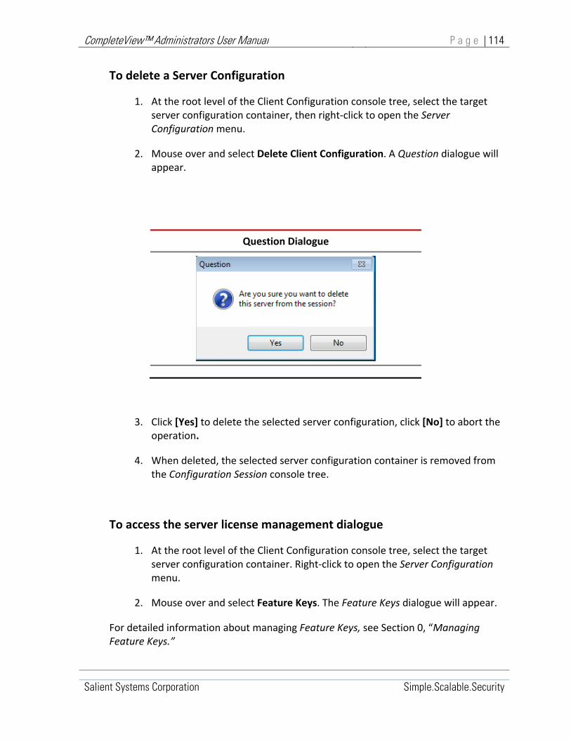
CompleteView™ Administrators User Manual P a g e | 114
Salient Systems Corporation Simple.Scalable.Security
To delete a Server Configuration
1. At the root level of the Client Configuration console tree, select the target server configuration container, then right‐click to open the Server Configuration menu.
2. Mouse over and select Delete Client Configuration. A Question dialogue will appear.
Question Dialogue
3. Click [Yes] to delete the selected server configuration, click [No] to abort the operation.
4. When deleted, the selected server configuration container is removed from the Configuration Session console tree.
To access the server license management dialogue
1. At the root level of the Client Configuration console tree, select the target server configuration container. Right‐click to open the Server Configuration menu.
2. Mouse over and select Feature Keys. The Feature Keys dialogue will appear.
For detailed information about managing Feature Keys, see Section 0, “Managing Feature Keys.”

CompleteView™ Administrators User Manual P a g e | 115
Salient Systems Corporation Simple.Scalable.Security
To reload a server configuration
1. At the root level of the Server Configuration console tree, select the target server configuration container, then right‐click to open the Server Configuration menu.
2. Mouse over and select Reload Configuration.
If the current configuration has not been saved since the last edit, a Question dialogue will appear.
Question Dialogue
To proceed without saving, click [Yes]. Edits to the current configuration will be discarded. To abort the operation click [No].
3. If edits to the current configuration have been saved or can be discarded, the selected server configuration container is reloaded from its source configuration file.

CompleteView™ Administrators User Manual P a g e | 116
Salient Systems Corporation Simple.Scalable.Security
To save a server configuration
1. At the root level of the Server Configuration console tree, select the target server configuration object. Right‐click to open the Server Configuration menu.
2. Mouse over and select Save Configuration. An Information dialogue will appear.
Information Dialogue
Figure 12‐4, Information Dialogue
3. In the Information dialogue, click [OK].
Out of Date Configuration Warning
If, while one Administrator is configuring a server, a second Administrator has altered that same server's configuration file, an "Out of Date Configuration" warning message is displayed when the first Administrator attempts to save the server configuration. The first Administrator is prompted to either reload the latest configuration and lose his or her changes, or save the configuration and overwrite the second Administrator's configuration file.
Out of Date Dialogue
Figure 12-5, Out of Date Dialogue

CompleteView™ Administrators User Manual P a g e | 117
Salient Systems Corporation Simple.Scalable.Security
To load a server configuration
1. At the root level of the Client Configuration console tree, select the server configuration container to be loaded with a new configuration. Right‐click to open the Server Configuration menu. Mouse over and select Load Configuration From...
2. A Load Server Configuration from dialogue will appear.
Load Configuration From
3. In the Load Server Configuration from dialogue, input the IP Address, Username, and Password for the server whose configuration is to be loaded into the selected server configuration object.
Click [OK].
4. The selected Server Configuration container is loaded with the configuration file from the specified server.

CompleteView™ Administrators User Manual P a g e | 118
Salient Systems Corporation Simple.Scalable.Security
To save a Server Configuration
1. At the root level of the Server Configuration console tree, select the server configuration container to be saved, then right‐click to open the Server Configuration menu.
2. Mouse over and select Save Configuration To... A Save Server Configuration to dialogue will appear.
Save Configuration To
3. In the Save Server Configuration To dialogue, input the IP Address, Username, and Password for the server where the configuration will be saved. Click [OK].
4. A new Server Configuration container is created in the console tree and populated with configuration information from the specified server.

CompleteView™ Administrators User Manual P a g e | 119
Salient Systems Corporation Simple.Scalable.Security
To restore a server configuration backup
1. At the root level of the Server Configuration console tree, select the target server configuration container, then right‐click to open the Server Configuration menu.
2. Mouse over and select Load Backup.
Question Dialogue
If the current configuration has not been saved since the last edit, a Question dialogue will appear.
To proceed without saving, click [Yes]. The current configuration will be discarded when the backup configuration is restored. To abort the operation click [No].
If the current configuration has been saved since the last edit or can be discarded, an Open dialogue will appear.
3. Using the Open dialogue, navigate to and select the configuration backup file to be loaded into the selected Server Configuration container.
4. Click [Open]. The selected server configuration backup file is restored to the selected server configuration container.

CompleteView™ Administrators User Manual P a g e | 120
Salient Systems Corporation Simple.Scalable.Security
To save a server configuration backup
1. At the root level of the Server Configuration console tree, select the server configuration container that will be used to create the configuration backup file. Right‐click to open the Server Configuration menu.
2. Mouse over and select Save Backup. A Save As dialogue will open.
3. Using the Save As dialogue, navigate to a destination folder and input a Filename for the backup configuration file being created.
4. Click [Save], a backup file is created from the selected configuration to the Destination Folder using the specified Filename.
By default, the Save As dialogue opens in the CompleteView installation folder. Backup files may be created in the CompleteView installation folder, or the System Administrator may use the Save As dialogue to navigate to any destination disk folder or network share where the backup file will be created using the specified filename.

CompleteView™ Administrators User Manual P a g e | 121
Salient Systems Corporation Simple.Scalable.Security
To access User functions from the server configuration menu
1. At the root level of the Server Configuration console tree, select the target server configuration container. Right‐click to open the Server Configuration menu.
2. Mouse‐over User. The User submenu will open.
For detailed information about managing Server Configuration Users, refer to Section 0, “Creating and Managing Users/Groups.”
To access Camera functions from the server configuration menu
1. At the root level of the Server Configuration console tree, select the target server configuration container. Right‐click to open the Server Configuration menu.
2. Mouse‐over Camera. The Camera submenu will open.
For detailed information about managing Server Configuration Cameras, refer to Section 0, “Creating and Managing Cameras.”
To access Alarm Device functions from the server configuration menu
1. At the root level of the Server Configuration console tree, select the target server configuration container. Right‐click to open the Server Configuration menu.
2. Mouse‐over Alarm Device, the Alarm Device submenu will open.
For detailed information about managing Server Configuration Alarm Devices, refer to Section 0, “Creating and Managing Alarm Devices.”
To access Volume functions from the server configuration menu
1. At the root level of the Server Configuration console tree, select the target server configuration container. Right‐click to open the Server Configuration menu.

CompleteView™ Administrators User Manual P a g e | 122
Salient Systems Corporation Simple.Scalable.Security
2. Mouse‐over Volume, the Volume submenu will open.
For detailed information about managing Server Configuration Volumes, refer to Section 0, “Creating and Managing Volumes.”
To access Schedule functions from the server configuration menu
1. At the root level of the Server Configuration console tree, select the target client configuration container. Right‐click to open the Server Configuration menu.
2. Mouse‐over Schedule, the Schedule submenu will open.
For detailed information about managing Server Configuration Schedules, refer to Section 0, “Creating and Managing Schedules.”

CompleteView™ Administrators User Manual P a g e | 123
Salient Systems Corporation Simple.Scalable.Security
Configuring the Server Configuration
Server Configurations, Server General Settings Window
The Server Container <General> window presents configuration parameters related to network communications, directory service authentication, and video analytics. The <General> pane also provides access to server license information.
Start>All Programs>CompleteView>System Configuration>Configure Servers>{Selected Server}>General
Server Configuration – General Tab
Figure 12‐6, Server Configuration ‐ General

CompleteView™ Administrators User Manual P a g e | 124
Salient Systems Corporation Simple.Scalable.Security
<General> Network Communication Settings
Friendly Server Name Specifies logical name used to access the server from the network.
TCP Port Numbers Specifies the network port numbers used to communicate with the server.
Table 12‐2, Server Configuration Network Settings
The Friendly Server Name corresponds to the Microsoft Windows local Computer Name. CompleteView™ references servers using the Friendly Server Name rather than an IP address.
The TCP Port Numbers define the network ports CV servers use to communicate with CV clients. By default, these are TCP 4242 and TCP 4343 where:
Data Port = 4242
Command Port = 424
The CV Data port is used by the server to listen for and respond to CV client requests.
The CV Command Port is needed for backward compatibility with CompleteView™ 1.x installations.
The Active Directory Authentication section establishes the credentials that CompleteView™ uses to authenticate users with the Active Directory domain.
<General> Active Directory Authentication
Domain Active Directory domain name
Username Active Directory username
Password Active Directory password
Re‐authentication Set User/Group re‐authentication frequency.
Table 12‐3, General Tab AD Items

CompleteView™ Administrators User Manual P a g e | 125
Salient Systems Corporation Simple.Scalable.Security
Domain Specifies the name of the AD domain used to authenticate an account. This is usually the internal (private) network domain.
Active Directory Username the User Account name used to authenticate with the specified AD domain.
Active Directory Password the User Account password used to authenticate with the specified AD domain.
Re‐authentication Frequency specifies the frequency of user and group re‐authentications.
CompleteView™ re‐authenticates users and groups with Active Directory after initial successful login. By default, re‐authentications happen upon every client request.
Re‐authentication Frequency enables periodic re‐authentication where per‐user and per‐group intervals can be set independently.
Periodic re‐authentication eliminates the need to re‐authenticate upon every client request, and can therefore result in improved client performance.
Re‐authentication Frequency:
User: Specifies User authentication interval in minutes
Groups: Specifies Group authentication interval in minutes
The Video Analytics section presents configuration settings for Agent VI analytics integration.
<General> Video Analytics
Proxy Specify Agent VI local port proxy
Engine Specify Agent VI
Enabled Enable/disable analytics
Table 12‐4, General Tab Video Analytics Items
<General> Global Settings
Global Settings If checked, all newly added users or groups will have access to all cameras, and all newly added cameras will be accessible to all users and groups.
Table 12‐5, General Tab Global Settings

CompleteView™ Administrators User Manual P a g e | 126
Salient Systems Corporation Simple.Scalable.Security
Server Configurations, Server Logging Window
The Server Configuration Logging tab enables support personnel to select which system events will be posted to the CompleteView™ log file.
The Logging window is organized into two sections, The Events to Log window and the Packet Loss parameters section.
Start>All Programs>CompleteView>System Configuration>Configure Servers>{Server}>Logging
Log File Configuration
Figure 12‐7, Server Configuration – Logging Window

CompleteView™ Administrators User Manual P a g e | 127
Salient Systems Corporation Simple.Scalable.Security
<Logging>
Events to Log Select system events to log
Packet Loss Set packet loss reporting thresholds
Table 12‐6, Logging Tab Items
The Events to Log window contains a list of system events that can be selected for logging. Click to check the corresponding checkbox for a system event to be logged.
The Packet Loss parameters determine the threshold at which packet loss events are posted to the log.
Maximum acceptable (%) determines the packet loss per‐cent threshold at which packet loss events are posted. The default setting is 5 per cent(5%).
Reporting interval (s) determines the interval length of time over which a packet loss sum is calculated. The default setting is 3600 seconds (one hour).

CompleteView™ Administrators User Manual P a g e | 128
Salient Systems Corporation Simple.Scalable.Security
Server Configuration, Server Email Window
Various CompleteView™ functions incorporate event‐driven email alerts. The Server Configuration Email window presents parameters to identify the email server and account information used system‐wide for email alert functionality.
The Email window specifies:
Email server information
Email account information
Sender information
Start>All Programs>CompleteView>System Configuration>Configure Servers>{ Server}>Email
Email Configuration
Figure 12‐8, Server Configuration ‐ Email

CompleteView™ Administrators User Manual P a g e | 129
Salient Systems Corporation Simple.Scalable.Security
<Email>
Mail Server IP Address of the Email (SMTP) server
Authentication Enable authentication/set account credentials
Sender Information Identify sender and sender return address
Figure 12‐9, Email Configuration
Mail Server (SMTP) is the address of the outgoing mail server.
Authentication Parameters must be set to contain the email account credentials used by CompleteView™ when sending email notifications, where:
Authentication indicates that the outgoing mail server requires authentication. If authentication is required, check to select the Authentication checkbox.
Username must be set to the outgoing mail server account Username if authentication is required.
Password must be set to the outgoing mail server account Password if authentication is required.
Sender Information fields should be populated with information identifiying the sender of CompleteView™ alert emails.
Sender Name should contain the name of the CompleteView™ Alert email sender. For example, “CV Administrator “
Sender Email should contain the sender’s return email address. For example, [email protected]

CompleteView™ Administrators User Manual P a g e | 130
Salient Systems Corporation Simple.Scalable.Security
Server Configuration, Server Tracking Window
The Server Configuration <Tracking> window presents settings that apply to the CompleteView™ PTZ camera Auto‐Attendant function.
The Tracking window contains a Zone Priority scroll box and a group of tracking behavior controls.
Using the <Tracking> window, behaviors are assigned to each Zone Priority level. Zone Priority levels in turn are assigned to the motion detect Zones defined on a per camera basis. For more information on defining per camera motion detect Zones, refer to Section “The Motion Zones Dialogue.”
The Zone Priority Hold Time, Dwell Time, and Cycle tracking behaviors are applied to all motion zones having the same Zone Priority on all cameras.
Start>All Programs>CompleteView>System Configuration>Configure Servers>{Selected Server}>Tracking
Tracking Configuration
Figure 12‐10, Server Configuration ‐ Tracking

CompleteView™ Administrators User Manual P a g e | 131
Salient Systems Corporation Simple.Scalable.Security
<Tracking> Window
Zone Priority Select zone priority level to configure
Table 12‐7, Tracking Window
Zone Priority allows configuration of 10 motion zone priority levels, with ten (10) being the highestand one (1) being the lowest.
Tracking Behavior
Hold Time Dwell before responding to new motion detect event
Dwell Time Dwell before cycling
Cycle Alternate between simultaneous motion detect events
Table 12‐8, Tracking Behavior
Tracking Behavior
Hold Time indicates the number of seconds CompleteView™ dwells on a preset before responding to a lower‐priority alarm. When motion is detected in a zone, CompleteView will show a preset location from one or more PTZ cameras as configured in the Actions Editor. Hold Time has no effect if a new motion event is in a higher priority zone than the currently alarmed zone, as CompleteView will respond to the higher priority zone immediately.
Dwell Time indicates the number of seconds that CompleteView™ should remain on a preset location before cycling.
Cycle enables Zone Cycling. When motion is detected in multiple zones, and the zones are configured with the same priority level, CompleteView™ will alternate between the presets that they were associated with using the Actions Editor.
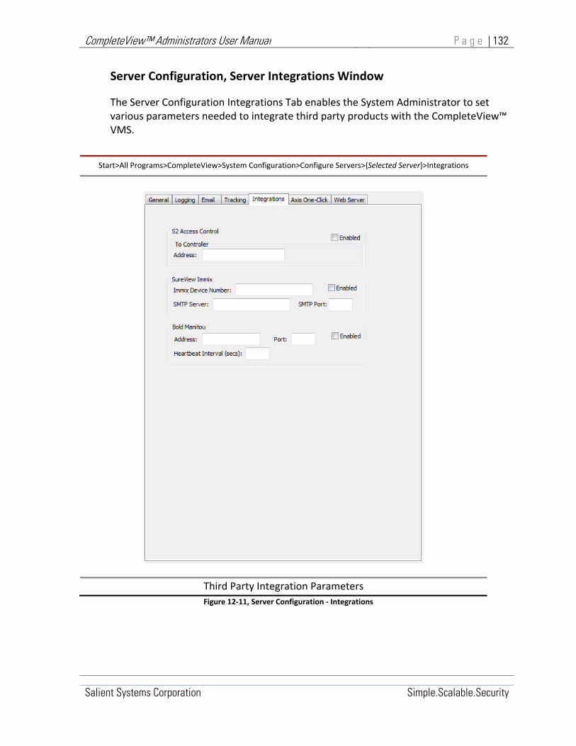
CompleteView™ Administrators User Manual P a g e | 132
Salient Systems Corporation Simple.Scalable.Security
Server Configuration, Server Integrations Window
The Server Configuration Integrations Tab enables the System Administrator to set various parameters needed to integrate third party products with the CompleteView™ VMS.
Start>All Programs>CompleteView>System Configuration>Configure Servers>{Selected Server}>Integrations
Third Party Integration Parameters
Figure 12‐11, Server Configuration ‐ Integrations

CompleteView™ Administrators User Manual P a g e | 133
Salient Systems Corporation Simple.Scalable.Security
S2 Access Control Parameters
Address Field: Enter the IP address of the S2 Netbox controller
Enabled Checkbox: Check to enable communications with the S2 Netbox controller
Table 12‐9, S2 Access Control Parameters
SureView Immix Parameters
Immix Device Number Field:
Enter the Immix Device number associated with the present CompleteView™ Server.
SMTP Server Field Enter the IP address of the SureView Immix server.
SMTP Port Field Enter the network port number the SureView Immix server uses for SMTP communications.
Enabled Checkbox: Check to enable communications with the SureView Immix controller.
Table 12‐10, SureView Immix Parameters
Bold Manitou Parameters
Address Field: Enter the IP address of the Bold Manitou server that will receive CompleteView™ alerts.
Port Enter the network port number used by the Bold Manitou server to receive CompleteView™ alerts.
Heartbeat Interval Enter the time in seconds between heartbeat messages sent from the CompleteView™ server to Bold Manitou.
Enabled Checkbox: Check to enable communications with the Bold Manitou server.
Table 12‐11, Bold Manitou Parameters

CompleteView™ Administrators User Manual P a g e | 134
Salient Systems Corporation Simple.Scalable.Security
Server Configuration, Axis One‐Click Window
The Axis One‐Click Tab enables the System Administrator to set various parameters needed to integrate Axis One‐Click with the CompleteView™ VMS.
Start>All Programs>CompleteView>System Configuration>Configure Servers>{Selected Server}>Axis One‐Click Tab
Axis One‐Click Parameters
Figure 12-12, Server Configuration ‐ Axis One Click

CompleteView™ Administrators User Manual P a g e | 135
Salient Systems Corporation Simple.Scalable.Security
Axis Dispatch Server
Dispatch Server Field:
Contains the Axis Dispatch Server hostname
User Name Field: Enter the Axis Dispatch Server account username obtained from Salient Systems.
Password Field Enter the Axis Dispatch Server account password obtained from Salient Systems.
Table 12‐12, Axis Dispatch Server Parameters
Axis One‐Click Component
External Address : Port
Enter the One Click Proxy server public (external) IP address and port number.
Internal Address : Port
Enter the One Click Connection Component private (internal) network IP address and port number.
Certificate Name
Enter the filename of the installed digital certificate.
The default certificate name is shown
The default path is C:\Program Files\Axis Communications\AXIS One‐Click Connection Component\stserver_ca.crt
Custom installations may require that a fully qualified pathname be specified.
Table 12‐13, Axis One‐Click Component Parameters

CompleteView™ Administrators User Manual P a g e | 136
Salient Systems Corporation Simple.Scalable.Security
Server Configuration, Web Server
The Web Server tab enables the System Administrator to activate or deactivate either or both the Embedded Web Server and Embedded Secure Web Server. The Web Client runs in the Microsoft Silverlight™ environment, which requires a port in the 4502‐4534 range. Configure either or both server ports with a unique port number within that range. Server authentication certificates may be modified by clicking the [Edit] button.
Start>All Programs>CompleteView>System Configuration>Configure Servers>{Selected Server}>Web Server Tab
Web Server Parameters
Figure 12-13, Server Configuration – Web Server

CompleteView™ Administrators User Manual P a g e | 137
Salient Systems Corporation Simple.Scalable.Security
Server Configuration, Users/Groups
CompleteView™ Users/Groups exist separately on both client and server machines.
In the video server, users and groups provide the means to convey camera access permissions, PTZ priorities, and API access to CompleteView™ clients.
In the video client, Users and Groups control access to video presentation View Layouts. Video client users gain access to live and recorded camera video from networked servers by automatically logging on to server user accounts when camera video from servers is accessed via view layouts.
Users/Groups Functional Overview
In the CompleteView™ Server, Users are persons or roles that require access to system resources such as live or recorded camera video.
Users are represented in the server configuration as User Objects in the Users/Groups container. The user object establishes a user account that provides the means to authenticate legitimate users via a username/password combination.
User objects convey camera access permissions to CompleteView™ clients, establish PTZ priorities used to resolve contention among users for control over specific cameras, and convey API access permission.
Groups provide a means to convey identical access permissions and PTZ priorities to multiple users.
Groups are represented in the server configuration as Group Objects in the Users/Groups container. During system configuration, users can be assigned membership in a group. When assigned to a group, the CompleteView™ user inherits the groups’ camera access permissions and PTZ priorities from the group settings. Membership in a group does not affect user authentication. Regardless of group membership, users must authenticate with their individual account credentials at login time.

CompleteView™ Administrators User Manual P a g e | 138
Salient Systems Corporation Simple.Scalable.Security
Creating and Managing Server Users/Groups
Commands available from the server configuration User Menu are used to create and manage video server users and groups.
To access the User Menu, select a user or group object and then right‐click. The User Menu will drop‐down to display.
The User Menu can also be accessed from the configuration console menu bar Server Configuration menu. Refer to section 0
Commonly used User Menu commands can also be invoked from the configuration console toolbar. Refer to section 0.
Start>All Programs>CompleteView>System Configuration>Configure Servers>Users/Groups
New Group Create a new Group object
New User Create a new User object.
Clone
Create a new user using the configuration settings of the currently selected User.
Delete Delete selected User or Group
New Password Create a new password for the selected User.
Click to select User/Group, right click opens menu
Table 12‐14, Server Configuration User Menu

CompleteView™ Administrators User Manual P a g e | 139
Salient Systems Corporation Simple.Scalable.Security
To create a new Group
1. In the Server Configuration console, select the Users/Groups container, then right click to open the Users/Group menu.
2. Mouse over and select New Group. A New Group dialogue will appear.
3. In the New Group dialogue box, enter a name for the group container. Click [OK].
4. The new group container is created in the Users/Group container and is ready for configuration.
To create a new User
1. In the Server Configuration console, select the Users/Groups container. Right click to open the Users/Group menu.
2. Mouse over and select New User. A New User dialogue will appear.
3. In the New User dialogue box, enter a name for the new user object. Click [OK]. A Password dialogue will appear.
4. In the Password dialogue box, enter a password for the new user object. Click [OK]. A Verify Password dialogue will appear.
5. In the Verify Password dialogue box, re‐enter the password previously entered for the new user object. Click [OK].
6. The new user object is created in the Users/Groups container and is ready for configuration.
To Clone a User
1. In the Server Configuration console, select the Users/Groups container. Right click to open the Users/Group menu.
2. Mouse over and select Clone. A New User dialogue will appear.
3. In the New User dialogue box, enter a name for the new user object. Click [OK]. A Password dialogue will appear.

CompleteView™ Administrators User Manual P a g e | 140
Salient Systems Corporation Simple.Scalable.Security
4. In the Password dialogue box, enter a password for the new user object. Click [OK]. A Verify Password dialogue will appear.
5. In the Verify Password dialogue box, re‐enter the password previously entered for the new user object. Click [OK].
6. The cloned user object is created in the Users/Groups container and is ready for configuration.
To delete a User or Group
1. In the Server Configuration console, expand the Users/Groups container.
2. Select the User or group to be deleted, then right click to open the Users/Group menu.
3. Mouse over and select Delete. A Remove User dialogue will appear.
4. In the Remove User dialogue, click [Yes] to delete the selected User or Group.
‐ OR –
Click [No] to abort the operation.
To a set a new password for a User
1. In the Server Configuration console, expand the Users/Groups container.
2. Select the User or group to be deleted, then right click to open the Users/Group menu.
3. Mouse over select New Password. A New Password dialogue will appear.
4. In the New Password dialogue box, enter a new password for the selected use. Click [OK]. A Verify Password dialogue will appear.
5. In the Verify Password dialogue box, re‐enter the password previously entered for the selected user object. Click [OK].

CompleteView™ Administrators User Manual P a g e | 141
Salient Systems Corporation Simple.Scalable.Security
Configuring Server Users/Groups
Server Users/Groups, Administration Window
The Users/Groups administration window presents attributes that can be set for Group containers and User objects.
When an attribute is set for a selected Group container, it will be inherited by all User objects within the Group.
When an attribute is set for a single selected User object, only the selected User will be affected.
Start>All Programs>CompleteView>System Configuration>Configure Servers>{Server}>Users/Groups>{User}>Administration
Figure 12‐14, Users/Groups Administration Tab

CompleteView™ Administrators User Manual P a g e | 142
Salient Systems Corporation Simple.Scalable.Security
The <Administration> window contains a group of selectable attributes and a membership window.
Selectable Attributes
Administrator Enable Administrator permissions for selected user
Log Events Log user activity
Active Directory Authentication
Manage User/Group via Active Directory.
Table 12‐15, User/Group Selectable attributes
The Administrator checkbox sets Administrator permissions for the selected User or Group.
If selected relative to a Group, all members of that group will inherit Administrator permissions. If selected relative to a single User, only the selected User will be granted Administrator permissions.
Administrator permissions enable users to modify CompleteView™ server configurations.
The Log Events checkbox causes system activity for the selected User or Group to be logged.
The Active Directory Authentication checkbox indicates that the Windows® Active Directory service centrally manages the selected user or group. Users and groups managed by Active Directory cannot be modified from within CompleteView™.

CompleteView™ Administrators User Manual P a g e | 143
Salient Systems Corporation Simple.Scalable.Security
Membership Box
User Membership List Group Membership List
Figure 12‐15, User/Group Membership Box
The Membership Box within the <Administration> window lists membership relationships between Users and Groups.
Memberships can be established or revoked by selecting or de‐selecting listed Users or Groups via their corresponding checkbox.
If a User object is selected in the Server Configuration console tree, The Membership Box lists all available Groups in the CompleteView™ system and indicates to which groups the selected user is a member.
A selected User can be added to a listed group by selecting the corresponding checkbox for that group.
A selected User can be removed from a listed group by de‐selecting the corresponding checkbox for that group.
If a Group object is selected in the Server Configuration console tree, the Membership Box lists all available Users in the CompleteView™ system and indicates which Users have membership in the selected Group.
Listed users can be added to a selected group by selecting the corresponding checkbox for that User.
Listed users can be removed from a selected group by de‐selecting the corresponding checkbox for that user.

CompleteView™ Administrators User Manual P a g e | 144
Salient Systems Corporation Simple.Scalable.Security
Users/Groups, Camera Window
Start>All Programs>CompleteView>System Configuration>Configure Servers>{Server}>Users/Groups>{User}>Administration
Figure 12‐16, Users/Groups Camera Tab
PTZ Section
PTZ Priority User/Group PTZ control access priority
Table 12‐16, PTZ Priority

CompleteView™ Administrators User Manual P a g e | 145
Salient Systems Corporation Simple.Scalable.Security
Permissions, Camera
Camera List Lists cameras available in the CompleteView™ system
Camera Permission Attributes
Lists attributes that can be independently associated with each camera
Table 12‐17, Camera Permissions
Camera Permissions, Attributes
View Enable user live viewing
Playback Enable user archive viewing
Snapshot Enable user snapshots
Audio Enable audio access on capable devices
Export Enable user Exports
PTZ Enable user PTZ controls
Light Enable user light control
Table 12‐18, Camera Permission Attributes
Permissions, Presets
Preset List List of PTZ presets allowed for the selected camera
Preset Permission Attributes
List attributes that can be independently associated with each PTZ preset.
Table 12‐19, Preset Permissions
Presets Permissions, Attributes
Set Permit user to modify selected preset.
Show Permit user to access selected preset.

CompleteView™ Administrators User Manual P a g e | 146
Salient Systems Corporation Simple.Scalable.Security
Table 12‐20, Preset Permission Attributes

CompleteView™ Administrators User Manual P a g e | 147
Salient Systems Corporation Simple.Scalable.Security
Users/Groups, Advanced Window
The Users/Groups Advanced Tab Window contains settings that enable third‐party control of the CompleteView™ server via the CompleteView™ Application Programming Interface (API).
When enabled, permission to use the API is granted to the User/Group currently selected in the server configuration, console tree.
Start>All Programs>CompleteView>System Configuration>Configure Servers>{Server}>Users/Groups>{User}>Advanced
Figure 12‐17, Users/Groups Advanced Window
The Users/Groups Advanced Window contains a warning disclosing potential security risks associated with allowing remote control of the CompleteView™ server, a

CompleteView™ Administrators User Manual P a g e | 148
Salient Systems Corporation Simple.Scalable.Security
checkbox control to acknowledge having read the warning, and a checkbox control to enable the API for the selected User or Group.
Presets Permissions, Attributes
I have read… Acknowledge security risks.
Grant user access… Permit API access to selected user.
Table 12‐21, Presets Permissions, Attributes
When selected, the “I have read…” checkbox enables the “Grant access…” checkbox.
When selected, the “Grant access…” permits API access to the selected user.
To enable API access for the selected user or group:
1. Read and understand the security admonishment.
2. Select the I Have Read… checkbox. The Grant user access… checkbox will become enabled.
3. Select the Grant user access… checkbox. API access by the selected user or group is now permitted.

CompleteView™ Administrators User Manual P a g e | 149
Salient Systems Corporation Simple.Scalable.Security
Server Configurations, Cameras
The primary function of cameras is to provide video streams to the CompleteView™ server. The fundamental function of the CompleteView™ server is to record camera video streams and to make both live and recorded camera video available to CompleteView™ clients. The CompleteView™ server performs stream processing of camera video in order to automate system operation and to provide a number of advanced features to the end user.
Many cameras also incorporate advanced features such as Pan‐Tilt‐Zoom (PTZ), Edge Storage and automatic On Camera Alerting. CompleteView™ fully integrates with many of these features on certain cameras.
For each physical camera in the system, there is a camera object in the server configuration file, Cameras container. Camera objects specify the configuration settings and properties for their associated physical device. Camera object properties and settings vary widely from camera to camera depending upon the camera type, manufacturer, model and capabilities.
The camera objects in the Cameras container represent three types of camera:
Analog Cameras
IP Cameras
QuickTrack Cameras
Analog Cameras
Analog surveillance cameras generate analog video signals and connect directly to Salient video capture cards in the CompleteView™ server. The video capture card converts the analog signal into a digital stream for processing and recording.
Once installed, a fixed‐analog camera provides its video signal to the CompleteView™ server via coaxial cable and requires no further maintenance or control communications.
Some analog cameras are capable of Pan‐Tilt‐Zoom (PTZ) control. Analog PTZ cameras typically accomplish PTZ control communications via a separate EIA Standard RS485 serial communications interface. The CompleteView™ server supports analog camera PTZ communications via onboard EIA Standard RS232 COM1 through COM4 serial ports. In the server computer, the COM1 through COM4 serial ports are typically virtualized via a USB interface, and require an external USB to RS485 converter.

CompleteView™ Administrators User Manual P a g e | 150
Salient Systems Corporation Simple.Scalable.Security
Analog Camera PTZ Serial Ports
Table 12‐22, Analog Camera PTZ Control
Over‐the‐coax control technologies, such as Pelco's Coaxitron®, are not directly supported by CompleteView™. However, it is possible to utilize Coaxitron® via intermediary hardware.
The most common solution to controlling 16 or fewer Pelco PTZ cameras via Coaxitron utilizes the Pelco CM‐6700 video matrix unit. Configure the second serial port (COM B) on the CM‐6700 for RS232 communications, and configure CompleteView™ to use the Pelco ASCII protocol. The CM‐6700 automatically converts from RS232 to Coaxitron® signaling, as well as from Pelco ASCII to Pelco P control protocols.
IP Cameras
Internet Protocol (IP) surveillance cameras generate digital video streams and connect to the CompleteView™ server via an IP network. IP cameras stream video according to several standard video compression and streaming protocols. Most are equipped with an embedded web server that can be accessed to enable control over any IP network such as the Internet or an intranet.
Configuring an IP camera often involves making complementary settings in the camera via its embedded web‐server interface, as well in CompleteView’s™ Configuration Utility.

CompleteView™ Administrators User Manual P a g e | 151
Salient Systems Corporation Simple.Scalable.Security
CompleteView™ supports advanced IP camera features including PTZ, Edge Storage, and on‐camera Alerting.
QuickTrack Cameras
A QuickTrack camera is a CompleteView™ virtual camera that allows Video Client users to record a series of cameras as one video feed.
An object in the server configuration Cameras container, a QuickTrack camera has no corresponding physical camera. In the Video Client, any camera can be dragged and dropped into the QuickTrack viewing panel to have its video displayed.
Additionally, the camera, along with any other camera brought into the QuickTrack panel, will be recorded as a single video feed. This allows for later review of all cameras being focused on.
Camera Pan Tilt Zoom (PTZ) Control
Pan‐Tilt‐Zoom camera control involves the ability to adjust a camera’s pitch and yaw within a range of motion. Using PTZ control, the camera position is adjusted to point at a desired location in order to achieve a particular field of view.
CompleteView™ can control many different PTZ camera models from a wide variety of manufacturers. Each manufacturer communicates with its PTZ cameras using a system of proprietary commands. These command sets are referred to as control protocols.
See Appendix ‘A’ for a list of PTZ control protocols supported by CompleteView.
Advanced Camera Features
CompleteView™ integrates with many advanced features offered by several camera manufacturers’ models.
Edge Storage
Edge storage is the ability of a camera to store video locally using onboard storage or to a stand‐alone Network Attached Storage (NAS) device.
During normal operation, CompleteView™ records video streams from cameras to its internal video storage volumes. Edge storage duplicates CompleteView™ video on the

CompleteView™ Administrators User Manual P a g e | 152
Salient Systems Corporation Simple.Scalable.Security
network, outside CompleteView™ storage volumes. When the video stream from a camera is interrupted, CompleteView™ will retrieve any missing recordings or fill any gaps in recordings from edge storage cameras and devices.
On‐Camera Alerting
CompleteView™ integrates with cameras that incorporate onboard event alerting features. Camera alerts initiate CompleteView™ motion/alarm recordings.
CompleteView™ Advanced Camera Features
CompleteView™ Motion Detection
CompleteView™ Motion Detection enables the System Administrator to define motion detect Zones within a camera field of view. During operation, video stream processing monitors motion‐detect Zones and generates a motion event when movement is detected within a Zone.
In turn, motion events are configured to trigger a number of possible responses, including motion recording, alarm triggering, and Auto‐Attendant activity.
CompleteView™ Digital PTZ
CompleteView™ video stream processing provides a Digital PTZ feature where PTZ capabilities are enabled within the fixed field of view of a non‐PTZ capable digital camera.
Digital PTZ allows the system operator to zoom in on an area within the camera’s field of view to get a closer look at activity in the screen. Once zoomed in, the user can pan and tilt the view, operate preset positions, and perform most functions that are available on traditional, mechanical PTZ cameras.
CompleteView™ PTZ Location Presets
PTZ Location Presets are the primitive elements that enable automated PTZ camera operation.
A PTZ camera preset is a pre‐determined set of viewing coordinates within a camera’s field of motion and view. Using the Live View dialogue, position a PTZ camera within its field of motion in order to achieve the desired field of view. Once a desired field of view is acquired, the Presets controls in the Live View dialogue can save the camera position as a Preset Location.

CompleteView™ Administrators User Manual P a g e | 153
Salient Systems Corporation Simple.Scalable.Security
CompleteView™ uses preset locations to automatically point a camera at well‐known locations in order to acquire a particular field of view.
Any number of Preset Locations may be associated with a PTZ camera.
Once recorded, Preset Locations can be used to create a Preset Tour for the camera, and to define Auto‐Attendant behaviors.
CompleteView™ Preset Tours
CompleteView™ facilitates automation of PTZ cameras by enabling a Preset Tour.
A preset tour consists of the PTZ camera alternating between two or more preset locations. Once preset locations have been defined for a camera, any or all may be included as part of the camera’s preset tour.
During operation, a camera on tour continuously proceeds through its presets included as part of its tour.
CompleteView™ Auto Attendant
CompleteView™ Auto‐Attendant automates system operation in response to motion detect events. Auto Attendant automatically redirects a PTZ camera or cameras to a location of interest upon detecting motion events from a fixed camera.
One or more motion detect Zones can be defined within the field of view for each fixed‐camera in the system. During operation, video stream processing monitors motion‐detect Zones and generates a motion event when movement is detected within a Zone.
One or more Preset Locations can be assigned to each PTZ‐camera in the system. The Auto‐Attendant can automatically redirect PTZ cameras having Preset Locations.
Upon detecting a motion event, the Auto‐Attendant takes action to redirect one or more PTZ cameras to assigned preset locations. Every PTZ camera participating in an Auto‐Attendant action can be redirected to a single Preset Location or directed to step through a sequence of Preset Locations.
An Auto‐Attendant action can be pre‐programmed for each motion detect zone defined on all fixed cameras in the system.

CompleteView™ Administrators User Manual P a g e | 154
Salient Systems Corporation Simple.Scalable.Security
The Auto‐Attendant prioritizes motion detection Zones, allowing PTZ cameras to hold a view on a high priority area. The cameras maintain their position even if motion has been detected in other, lower‐priority areas. The Auto‐Attendant automatically cycles between preset locations having equal priority levels.
CompleteView™ HTTP Notifications
CompleteView™ incorporates an embedded web server that provides an interface for cameras and other third party devices to remotely initiate and terminate camera recordings.
A third party device, such as an Axis camera, can trigger alarm or motion recording on a specified camera in CompleteView. When CompleteView’s web server is enabled, the third party device can send a specially formatted URL to tell CompleteView to start or stop alarm or motion recording on a specified camera.
Creating and Managing Camera Objects
The server configuration Cameras Menu enables a system administrator to manage camera objects.
While this section describes how to manage camera objects using the Cameras Menu, functions available from the Cameras Menu can also be accessed via corresponding buttons in the server configuration console toolbar.
Start>All Programs>CompleteView>System Configuration>Configure Servers>Cameras><{Camera}

CompleteView™ Administrators User Manual P a g e | 155
Salient Systems Corporation Simple.Scalable.Security
Add Camera Create a new IP Camera object.
Add QuickTrack Camera
Create a new QuickTrack Camera source.
Clone IP Camera Duplicate selected IP camera object.
Delete Camera Remove selected IP Camera object.
Move Up Reorder selected Camera object upward.
Move Down Reorder selected Camera object downward.
Live View View live video from selected camera.
Move/Copy IP Camera
Move IP Cameras between Servers.
Camera Search/Add
Search for cameras on the network.
Click to select Camera, right click opens menu
Figure 12‐18, Cameras Menu

CompleteView™ Administrators User Manual P a g e | 156
Salient Systems Corporation Simple.Scalable.Security
To create an IP Camera Object:
1. In the Server Configuration console tree, select the Cameras container. Right click to open the Cameras Menu.
2. Mouse over, and select Add Camera. A New Camera dialogue will appear.
3. In the New Camera dialogue box, enter a name for the IP Camera device object being created. Click [OK].
4. The new camera object is created in the cameras container and ready for configuration.
To create a QuickTrack camera source:
1. In the Server Configuration console tree, select the Cameras container. Right click to open the Cameras Menu.
2. Mouse over and select Add QuickTrack Camera. A New QuickTrack Camera dialogue will appear.
3. In the New QuickTrack Camera dialogue box, enter a name for the QuickTrack Camera object being created. Click [OK].
4. The new QuickTrack camera object is created in the cameras container and ready for configuration.
To clone an IP Camera Object:
1. In the Server Configuration console tree, select the Cameras container. Right click to open the Cameras Menu.
2. Mouse over and select Clone IP Camera. A New Camera dialogue will appear.
3. In the New Camera dialogue box, enter a name for the IP Camera object being created. Click [OK].
4. The cloned camera object is created in the schedules container and ready for configuration.

CompleteView™ Administrators User Manual P a g e | 157
Salient Systems Corporation Simple.Scalable.Security
To delete an IP Camera Object:
1. In the Server Configuration console tree expand the Cameras container. A list of camera objects will appear.
2. Select the camera to be deleted, then right click to open the Cameras Menu.
3. Mouse over and click Delete Camera. The selected camera object is removed from the server configuration Cameras container.
To reorder IP camera objects:
1. In the Server Configuration console tree expand the Cameras container. A list of Camera objects will appear.
2. Select the IP Camera Object to be moved.
3. Right click the selected Camera Object to open the Cameras Menu, then mouse over and click Move Up or Move Down as desired.
Reordering camera objects in the cameras container has no effect on the way CompleteView™ manages cameras.

CompleteView™ Administrators User Manual P a g e | 158
Salient Systems Corporation Simple.Scalable.Security
To Live View an IP Camera
1. In the Server Configuration console tree, select the Cameras container then right click to open the Cameras Menu.
2. Mouse over and select Live View. A Live View pop‐up window will appear.
Live View
View Window PTZ Presets
Figure 12‐19, Live View Dialogue
The Live View function is a convenient way to test each camera once it is configured.
The Live View pop‐up window is organized into three sections:
1. The View window
2. The PTZ Controls
3. The Preset Controls

CompleteView™ Administrators User Manual P a g e | 159
Salient Systems Corporation Simple.Scalable.Security
Live View PTZ Controls
Slider Control Adjust the PTZ speed
Arrow Buttons Each button moves the camera incrementally in the direction clicked.
Zoom Buttons Incrementally change the camera zoom‐level.
Focus Buttons Incrementally change the camera focus.
Iris Buttons Manually adjust the iris of the selected camera.
Table 12‐23, Live View PTZ Controls

CompleteView™ Administrators User Manual P a g e | 160
Salient Systems Corporation Simple.Scalable.Security
Live View Preset Controls
Presets List of existing presets by preset ID number and name
Presets Name Enter the desired name of the preset, select the number to which the name will correspond, set the camera, click Set. (Note: Name is only configurable for mechanical PTZ cameras.)
[Show] Button Show presets for the camera being configured
[Set] Button Set the current camera position (and name, if applicable) as a preset location.
Table 12‐24, Live View Preset Controls

CompleteView™ Administrators User Manual P a g e | 161
Salient Systems Corporation Simple.Scalable.Security
To move/copy IP Cameras:
Moving an IP Camera involves moving a camera object from a source server configuration to a destination server configuration.
Copying an IP Camera duplicates a camera object within a server configuration.
To move or copy IP Cameras use the Move or Copy IP Cameras dialogue. To open the Move or Copy IP Cameras dialogue:
1. In the Server Configuration console tree, select the Cameras container. Right click to open the Cameras Menu.
2. Mouse over and select Move/Copy IP Cameras… The Move or Copy IP Cameras dialogue will appear
Move or Copy IP Cameras
Source Server Button Group Destination Server
Figure 12‐20, Move or Copy IP Cameras

CompleteView™ Administrators User Manual P a g e | 162
Salient Systems Corporation Simple.Scalable.Security
The CompleteView™ VMS is licensed on a per camera basis. Moving cameras between servers requires available IP Camera license(s) on the destination server.
The Move or Copy IP Cameras dialogue is organized into three verticle sections:
The leftmost section presents the source, server configuration.
The rightmost section presents the destination, server configuration.
The middle section consists of two button groups that enable camera objects to be moved between the source and destination servers.
The source and destination sections of the Move or Copy IP Cameras dialogue, each consists of a Server drop‐down menu and a Cameras Window.
The Server drop‐down menu contains a list of available source or destination servers. Use this control to select the source and destination server configurations, respectively.
The Cameras Window contains a list of available camera objects in the selected source and destination server configurations. Available cameras are each listed alongside a corresponding checkbox. Use the corresponding checkbox to select or deselect the camera objects to be moved or copied.
To Copy an IP Camera:
1. In the Move or Copy IP Cameras dialogue source section, click the carat next to the Server drop‐down menu. A menu list of available source servers will open.
2. Mouse over and select the desired source server.
3. In the Move or Copy IP Cameras dialogue destination section, click the carat next to the Server drop‐down menu. A menu list of available destination servers will open.
4. Mouse over and select the desired destination server.
5. In the Move or Copy IP Cameras dialogue source section, click to check the corresponding checkbox for each camera to be copied.

CompleteView™ Administrators User Manual P a g e | 163
Salient Systems Corporation Simple.Scalable.Security
6. In the Move or Copy IP Cameras button group section, click the [Copy‐>] button. The selected camera objects are copied from the source Cameras Window to the destination Cameras Window.

CompleteView™ Administrators User Manual P a g e | 164
Salient Systems Corporation Simple.Scalable.Security
To Move an IP Camera:
1. In the Move or Copy IP Cameras dialogue source section, click the carat next to the Server drop‐down menu. A menu list of available source servers will open.
2. Mouse over and select the desired source server.
3. In the Move or Copy IP Cameras dialogue destination section, click the carat next to the Server drop‐down menu. A menu list of available destination servers will open.
4. Mouse over and select the desired destination server.
5. In the Move or Copy IP Cameras dialogue Cameras Window, click to check the corresponding checkbox for each camera to be moved.
6. In the Move or Copy IP Cameras source section, click the [Move‐>] button. The selected camera objects are moved from the source Cameras Window to the destination Cameras Window.
To search for and add IP Cameras:
The Camera Search/Add dialogue automatically discovers and lists µPnP compatible IP cameras attached to the network.
IP Cameras discovered in this way can then be automatically added to the current server configuration. Discovered cameras may be added singly or multiple discovered cameras may be added simultaneously.
When adding discovered cameras, the Camera Search/Add dialogue automatically tests the video stream from each camera being added. Upon successful testing a camera object is created for each tested camera and placed in the server configuration Cameras container.
If multiple cameras are added simultaneously, all of the cameras being added must use the same video compression type and share the same username/password credentials.
The CompleteView™ VMS is licensed on a per camera basis. Adding cameras to the current server configuration requires available IP Camera license(s).

CompleteView™ Administrators User Manual P a g e | 165
Salient Systems Corporation Simple.Scalable.Security
To detect µPnP compatible IP Cameras open the Camera Search /Add dialogue:
1. In the Server Configuration console tree, select the Cameras container then right click to open the Cameras Menu.
2. Mouse over and select Camera Search Add…. A Camera Search /Add dialogue will appear.
Camera Search/Add Dialogue
Figure 12‐21, Camera Search/Add Dialogue
When the Camera Search /Add dialogue displays, a passive µPnP discovery is in process. As µPnP notifications are received, the Camera Search /Add dialogue Discovered devices window is automatically populated with discovered devices.
The µPnP protocol utilizes multicast transmissions. Depending on the network configuration, multicast transmissions might not be propagated across physical network segments or IP subnets.

CompleteView™ Administrators User Manual P a g e | 166
Salient Systems Corporation Simple.Scalable.Security
To view the µPnP device information for a discovered device:
1. In the Camera Search /Add dialogue, double‐click to select a listed device. A Device Info dialogue will appear containing the µPnP information for the selected device.
2. Click [OK] to close the Device Info dialogue.
To add discovered cameras to the Server Configuration:
1. In the Camera Search /Add dialogue, select a listed camera. Multiple cameras can be selected by depressing and holding the [CTRL] or [SHIFT] key and click the listed cameras for selection.
2. In the Camera Search /Add dialogue, Username and Password textbox, enter a Username and Password, respectively, for the selected camera/cameras.
3. In the Camera Search /Add dialogue using the Stream Type radio buttons, select a video stream type.
4. In the Camera Search /Add dialogue, click [Add Selected Cameras]. An automated test of each selected camera begins.
The Camera Search /Add dialogue, Discovered devices window, Status column, indicates automated test progress and results as follows:
1.
Status Testing indicates that the automated camera‐add function is attempting to connect to the camera under test and acquire a video stream.
Status Added indicates that the automated test was successful and a camera object has been created for the camera under test.
Status Description
Testing… Automated test in progress
Added/Passed Automated test successful
Failed… Automated test failed
Skipped Add camera operation aborted

CompleteView™ Administrators User Manual P a g e | 167
Salient Systems Corporation Simple.Scalable.Security
Status Failed… indicates that the automated test was not successful. When encountered, an Edit Camera dialogue automatically displays.
Status Skipped indicates that the Add Camera operation has been aborted for the camera under test.
The Edit Camera Dialogue
The Edit Camera dialogue automatically displays whenever an Add Camera operation initiated by the Camera Search/Add function fails.
This dialogue contains settings that determine how a failed camera will be treated.
Edit Camera Dialogue
Figure 12‐22, Camera Edit Dialogue

CompleteView™ Administrators User Manual P a g e | 168
Salient Systems Corporation Simple.Scalable.Security
To reconfigure and retest a failed camera:
1. In the Edit Camera dialogue, verify and edit as needed:
a. The cameras configured Manufacturer and Model specification
b. The cameras configured video stream type
c. The cameras configured RTSP port
d. The cameras configured logon credentials
2. In the Edit Camera dialogue, Actions section, select the Retry radio button.
3. Click [Perform Action]. The automated video acquisition test is repeated.
To add a failed camera unconditionally:
1. In the Edit Camera, dialogue Actions section, select the Add without video acquisition test radio button.
2. Click [Perform Action]. The automated video acquisition test is not repeated and a camera object is unconditionally created for the camera under test.
To ignore a failed camera:
1. In the Edit Camera dialogue Actions section, select skip radio button.
2. Click [Perform Action]. The automated video acquisition test is not repeated and no camera object is created for the camera under test.

CompleteView™ Administrators User Manual P a g e | 169
Salient Systems Corporation Simple.Scalable.Security
Configuring Cameras
When a camera is selected in the Configuration Utility console tree, the console details pane contains a set of tabbed windows
Cameras, General Settings Window
The cameras <General> window contains settings relating to various camera parameters and video compressor settings.
The parameters and options available for configuration may vary depending the manufacturer and model of the camera being configured.
Start>All Programs>CompleteView>System Configuration>Configure Servers>Cameras>{Camera}>General
Figure 12‐23, Cameras General Tab

CompleteView™ Administrators User Manual P a g e | 170
Salient Systems Corporation Simple.Scalable.Security
Camera Parameter Settings
Enabled Specifies whether the camera input is enabled or disabled
Name An assigned unique name for the camera being configured
Video Quality Selects MPEG‐4 codec
Video Size Globally sets the video capture resolution for all cameras managed by the server being configured.
Lens Type Select standard or panomorph lens
Lens Orientation Select camera placement.
Lens Profile The registered panomorph lens number specific to Immervision, which can be found on the lens itself
Calibrate Fisheye (Only visible on Sentry360 models) – Used to launch calibration of certain Sentry360 fisheye cameras. See Appendix E for details.
Scheduled Recording FPS
Sets the recording frame rate for Scheduled video recordings
External Alarm Recording FPS
Sets the recording frame rate for External Alarm video recordings
Motion Detection FPS
Sets the recording frame rate for Motion Detection video recordings
Time Stamp Overlay Adds the date and time to the lower right‐hand corner of the video input
Camera Name Overlay
Adds the name of the camera, as defined in the Name setting, to the upper left‐hand corner of the video input
Stream Properties Overlay
Displays compression, bit rate, frame rate, and resolution information in the top left corner of the video input
Black and White Camera
Selects whether the camera connected to the input is black & white
Camera Adjustments
Camera Adjustments permits adjustments to be made to the video signal of directly‐connected analog cameras
Apply to all Cameras Applies selected settings of the current camera to ALL cameras
Table 12‐25, Camera Parameter Settings
The Enabled checkbox specifies that video input from the camera being configured is either enabled or disabled. Check this box to enable video from the camera being configured. The Enabled setting overrides the cameras’ recording Schedule, camera

CompleteView™ Administrators User Manual P a g e | 171
Salient Systems Corporation Simple.Scalable.Security
video is not recorded when a camera is disabled. In addition, both local and remote viewing of the camera is not available.
When a client connects to a disabled camera input, the user will receive a message indicating that connection to the server succeeded, but that the camera input is disabled.
The Name text box specifies the cameras assigned Name. The assigned name is used to identify the camera system‐wide and must be unique among all cameras in the system.
The Video Quality drop‐down menu selects the quality of video compressed using the MPEG‐4 codec. This setting affects both recorded and live‐view video.
MJPEG format will permit recording Scheduled recordings at a lower frame rate and Motion recordings at a higher frame rate. H.264 and MPEG4 will both record at the higher frame rate.
The Video Size drop‐down menu selects the video capture resolution for all cameras managed by the CompleteView™ Server. The actual video capture size specified by this configuration option cannot be overridden or otherwise changed by a video client.
When a mismatch occurs between the camera video size and the video size specified by a client, video viewing tile, the camera video will be adjusted accordingly.
For example, camera video sized to 160 x 120 and then displayed in a 640 x 480 CompleteView™ Client viewing tile will be stretched to fill the 640 x 480 display.
The Lens Type drop‐down menu applies only when using a supported panomorph lens on the selected camera.
The Lens Orientation setting applies to panomorph lenses, and will indicate Ceiling, Ground, or Wall.
Lens Profile describes the registered panomorph lens number, is specific to Immervision, and can be found on the lens.
The Scheduled Recording FPS drop‐down menu sets the video recording frame rate for Scheduled, continuous recording as specified in the camera recording Schedule.
The External Alarm Recording FPS drop‐down menu sets the video recording frame rate for video recorded during External Alarm events.

CompleteView™ Administrators User Manual P a g e | 172
Salient Systems Corporation Simple.Scalable.Security
The Motion Detection FPS drop‐down menu sets the video recording frame rate for video recorded during Motion Detect events.
The Time Stamp Overlay checkbox enables a date and time overlay at the lower right‐hand corner of the video input.
The Camera Name Overlay checkbox enables a camera Name overlay at the upper left‐hand corner of the video input. The camera Name is determined by the <General> window, Name setting.
The Stream Properties Overlay enables the display of compression, bitrate, frame rate, and resolution information.
The Black and White Camera checkbox specifies that the camera input is black and white video.
The Apply These Settings to All Cameras button applies selected settings from the current camera to all cameras on the server.
The selected settings include:
Time Stamp Overlay
Camera Name Overlay
Stream Properties Overlay
Video Quality
Keyframe Rate
Scheduled Recording FPS
External Alarm FPS

CompleteView™ Administrators User Manual P a g e | 173
Salient Systems Corporation Simple.Scalable.Security
Motion Detection FPS

CompleteView™ Administrators User Manual P a g e | 174
Salient Systems Corporation Simple.Scalable.Security
Camera Adjustments permits adjustments to be made to the video signal of directly connected analog cameras.
Gen I capture card adjustments:
Gen I Capture Card Adjustments
Brightness – Changes the brightness of the video.
Contrast – Changes the contrast of the video.
Hue – Changes the color balance of the video.
Saturation – Changes the color level of the video.
Sharpness – Changes the sharpness of the video.
Gamma – Changes the gamma level of the video.
White Balance – Changes the white balance of the video.
Backlight Comp – Enables / disables backlight compensation.
Defaults – Resets all adjustments to their default values.

CompleteView™ Administrators User Manual P a g e | 175
Salient Systems Corporation Simple.Scalable.Security
The checkboxes to the right of saturation, sharpness and gamma indicate whether automatic control of the adjustment is either enabled or disabled. Un‐check the ‘auto’ box in order to apply any change to these settings.
Gen II capture card adjustments:
Gen II Capture Card Adjustments
Brightness – Changes the brightness of the video.
Contrast – Changes the contrast of the video.
Hue – Changes the color balance of the video.
Saturation – Changes the color level of the video.

CompleteView™ Administrators User Manual P a g e | 176
Salient Systems Corporation Simple.Scalable.Security
Sharpness – Changes the sharpness of the video.
Defaults – Resets all adjustments to their default values.
Enable Deinterlacing – Analog video produces a picture (or frame) by “painting” two separate, interlaced visual fields. When Enable Deinterlacing is selected, CompleteView digitally combines both fields and presents them as one cohesive image, which is useful for video processing purposes. In the process of digitizing and combining the interlaced fields, some video artifacts and motion‐blurring may arise from the time delay intrinsic to the separate field renderings in the original interlaced video. CompleteView includes smoothing functionality to address the potential anomalies. Generally speaking, Enable Deinterlacing should be on, unless there is known deinterlacing of the video stream before it reaches the CompleteView server.
Enable Motion Based Smoothing – Initiates smoothing on deinterlaced video, based on detected motion in the camera’s field of view. If no motion is detected, no smoothing is applied. Use the slider to increase or decrease motion sensitivity.
Enable Median Smoothing – If checked, smoothing is always on.
Enable Noise Reduction – When selected, will apply an algorithm to “clean up” analog video, reducing grain and video artifacts. Use the Luma Strength slider to enhance or decrease the achromatic (black and white) elements of the video picture. Use the Chroma Strength slider to enhance or decrease the color elements of the video picture.
Stream Compression Settings
Stream Compression settings allow the System Administrator to specify the video compression used for the various streams that can originate from a single cameras' video.
Camera Video Stream Compression Settings
From Camera Select compression type for stream from camera
Record As Select compression type for recording
Stream as Select compression type for streaming to clients
Table 12‐26, Stream Compression Settings

CompleteView™ Administrators User Manual P a g e | 177
Salient Systems Corporation Simple.Scalable.Security
The “From Camera” compression setting specifies the compression used for a video stream as received from the camera.
The “Record As” compression setting specifies the compression used for a video stream as recorded to a video storage volume.
The “Stream As” compression setting specifies the compression used for the video stream provided to video clients.
GOP Length sets the preferred number Group Of Pictures CompleteView grabs from the camera.
The three camera video streams may be encoded independently using one of three CODECS:
MJPEG: IP cameras use MJPEG (Motion JPEG) video compression by default. MJPEG generates larger video files than Basic MPEG4. The larger video files use more disk space, and as a result, both video retention time is decreased and more network bandwidth is consumed. The MJPEG video compressor may also be used with analog CCTV cameras.
This video compressor is best suited to low frame‐rate camera sources, and those where there is constant large‐scale movement, such as a pan‐tilt‐zoom camera that is on a preset tour.
Enhanced MPEG4: This video compression codec utilizes the latest enhancements in MPEG4, resulting in extremely high quality MPEG4 video files that are much smaller than those compressed with MJPEG. When compared to Basic MPEG4, using this codec results in a slight increase in video retention time and a decrease in network bandwidth consumption. Enhanced MPEG4, however, allows video size to be different for each camera input using the codec.
H.264: This codec provides the highest level of compression resulting in the lowest files sizes and highest retention times.
H.264 consumes the most processing power (CPU cycles) as compared with the other codecs. When using H.264, it is highly recommended to select "Disable Stream Processing" in the <IP> window settings to reduce CPU utilization.

CompleteView™ Administrators User Manual P a g e | 178
Salient Systems Corporation Simple.Scalable.Security
Cameras, Volumes Window
The <Volumes> window enables the System Administrator to associate the camera being configured with video storage volumes available on the server. When required by established Schedules, video from the camera being configured is automatically stored in real‐time to its associated storage volumes.
Backup and Archive video volumes cannot be associated with a camera for automatically storing camera video.
Start>All Programs>CompleteView>System Configuration>Configure Servers>Cameras>{Camera}>Volumes
Figure 12‐24, Cameras Volumes Window

CompleteView™ Administrators User Manual P a g e | 179
Salient Systems Corporation Simple.Scalable.Security
Volumes Settings
Volume List of storage volumes available on the server
Table 12‐27, Volumes Settings
The <Volumes> window contains a Volume list box. The Volume list box contains a list of all storage volumes available for association with the camera being configured. Each volume in the list corresponds to a checkbox control.
To associate the camera being configured with a storage volume, select the checkbox control corresponding to the target storage volume.

CompleteView™ Administrators User Manual P a g e | 180
Salient Systems Corporation Simple.Scalable.Security
Cameras, IP Window
Start>All Programs>CompleteView>System Configuration>Configure Servers>Cameras>{Camera}>IP
Figure 12‐25, Cameras IP Window

CompleteView™ Administrators User Manual P a g e | 181
Salient Systems Corporation Simple.Scalable.Security
Camera IP Settings
Manufacturer Selects the camera manufacturer
Model Selects the camera model
Address Specify the cameras’ IP address
Camera ID Select the cameras’ channel number
HTTP Port Specify the camera web service TCP port number
RTSP/Stream/Control Port
Specify the camera RTSP port
Configure Access cameras’ web‐service configuration
Username Camera web service logon username
Password Camera web service logon password
Image Path Path to a still image on the camera
Timeout Camera communications timeout in seconds
Retries Camera communications retries
Stream Type Select video stream compression format
Disable Stream Processing
Disables any decoding of the video stream on the recording server
Compression of Recorded Video
use the original compressed image as received from the camera
Table 12‐28, Camera IP Settings
The Manufacturer drop down menu contains a list of supported cameras. Mouse over and select the manufacturer of the camera being configured.
The Model drop down menu contains a list of supported camera models from the selected manufacturer.
The Address text field specifies the hostname or IP address of the camera being configured. Enter the IP address or hostname of the IP camera.
CompleteView™ Administrators User Manual P a g e | 182
Salient Systems Corporation Simple.Scalable.Security
The Camera ID drop down menu applies only to multi‐channel analog to digital video encoders. The drop down menu contains the list of channels available on the encoder. Select the camera's channel number from this list.
The HTTP Port text field specifies the TCP port number serviced by the cameras built‐in web server. Enter the web‐server port number for the camera being configured.
The RTSP Port/Stream Port/Control Port text fields specify ports used to support the streaming protocol employed by the camera being configured. These fields appear depending upon the Manufacturer and Camera selected.
The RTSP Port applies to MPEG‐4 video streams only. The default RTSP port is 554.
The Stream Port and Control Port fields are complementary, and generally apply to implementations of the Real Time Transport (RTP)/Real Time Control (RTCP) Protocol pair.
The Configure button automatically launches a web browser and accesses the camera web server.
The Username and Password fields specify user account credentials needed to access the camera web service.
The Image Path field applies only to the Generic IP Camera drivers. Specify the path to a still image on the camera being configured.
For example, if the full path to the still image is 'http://myipcamera/images/still.jpg', then enter 'images/still.jpg' as the image path.
The Timeout control specifies the time in seconds CompleteView™ waits for responses to communication attempts with the camera. When a timeout occurs, the

CompleteView™ Administrators User Manual P a g e | 183
Salient Systems Corporation Simple.Scalable.Security
communication attempt will retry according to the value specified by the Retries control.
The default timeout is 3 seconds. Change the 3‐second timeout only at the direction of Salient support personnel.
The Retries Control specifies the quantity of attempts CompleteView™ will make to communicate with a camera before determining the camera is unreachable.
The default retry count is three (3). Change this setting only at the direction of Salient support personnel.
The Stream Type radio buttons select the CODEC used to decode video from the camera being configured.
The Disable Stream Processing checkbox disables all processing by the recording server of the video stream input from the camera. When stream processing is disabled, video is recorded exactly as received from the camera.
This option increases server performance, however, features such as transcoding, Dynamic Resolution Scaling, text overlay and motion detection, camera preview in setup, snapshot image attachments to email alerts, camera name overlay & timestamp overlay will not be available
Compression of Recorded Video – This switch controls whether or not CompleteView™ should use the original compressed image as received from the camera, or recompress the images using the video compressor specified in the <General> window of the camera configuration.
If the original video from the camera is chosen, CompleteView™ will be unable to add the date/time, camera name, or other text overlays to the archived video files. The overlays will appear in all live video streams.

CompleteView™ Administrators User Manual P a g e | 184
Salient Systems Corporation Simple.Scalable.Security
On Camera Alerting
CompleteView™ supports edge based device alarms on many manufacturers’ cameras. Alarms are contingent upon the feature set of the specific make and model of camera.
Start>All Programs>CompleteView>System Configuration>Configure Servers>Cameras>{Camera}>IP
Figure 12-26, Use On-Camera Alerting
The On‐Camera Alerting controls function in concert with the event and alarm feature set of many IP cameras. The list of available features will differ from camera to camera.
On‐camera alerting will work for cameras streaming MJPEG or MPEG4 video streams. Within the camera’s interface, 'Trigger Data' must be turned on for the camera to provide CompleteView with camera event notifications.

CompleteView™ Administrators User Manual P a g e | 185
Salient Systems Corporation Simple.Scalable.Security
Camera Specific, On Camera Alert Settings
Use On‐Camera Alerting Enables camera based alerting
Configure Alerts Open the Camera Alarm Events dialogue
Table 12‐29, On Camera Alert Settings
To enable camera‐based alerting, check the Use On‐Camera Alerting checkbox.
To configure camera‐based alerts, click the [Configure Alerts] button. The Camera Alarm Events dialogue will appear:
Figure 12‐27, Camera Alarm Event Configuration
The Camera Alarm Event Configuration dialogue lists a number of event types. Each event type is associated with one or more actions.

CompleteView™ Administrators User Manual P a g e | 186
Salient Systems Corporation Simple.Scalable.Security
Enable events and their associated actions by selecting the Alarm from the list, and selecting the Enable checkbox. Select the recording event type by selecting the Alarm, and choosing either Motion or Alarm from the dropdown menu. Click [OK] when done.
On‐Camera Events
Motion Events Trigger actions upon camera‐based motion detection
Audio Events Trigger actions upon camera‐based audio detection
Detect Tampering Triggers actions upon camera‐based tampering detection
On Camera IO Triggers Triggers actions upon camera‐based digital input activity
Video Loss Triggers actions upon encoder based video loss detection
Table 12‐30, Camera Alarm Events Sample
Each event type is able to trigger a recording
Event‐Triggered Recordings run for the duration of the event and are marked as either Alarm or Motion Detect recordings as described in the On‐Camera Event Configuration dialogue box.
Using HTTP Notifications
Cameras can trigger CompleteView™ Motion or Alarm recording in response to on‐camera events. The CompleteView™ integrated web‐server provides an HTTP command format used to receive HTTP notifications from third party devices.
Implementing camera‐based HTTP notifications requires configuration steps taken in CompleteView™ as well as on the camera.
Enable the CompleteView™ web server
Setup notification command URLs on the camera

CompleteView™ Administrators User Manual P a g e | 187
Salient Systems Corporation Simple.Scalable.Security
Axis One Click Connection
CompleteView supports Axis One Click Connection feature built into most Axis Communications cameras. Axis One Click Connection simplifies installation by reducing the IP configuration necessary to connect the camera to the CompleteView Video Management System. Please contact Salient for Axis One Click Connection setup documentation.
Cameras, PTZ Window
The Cameras <PTZ> window contains the settings required to enable Pan‐Tilt‐Zoom control over the camera being configured.
The <PTZ> window organizes camera PTZ settings into three groups:
PTZ Settings
Timeouts
Preset Tour
Start>All Programs>CompleteView>System Configuration>Configure Servers>Cameras>{Camera}>PTZ
Figure 12‐28, Cameras PTZ Window

CompleteView™ Administrators User Manual P a g e | 188
Salient Systems Corporation Simple.Scalable.Security
Camera PTZ Settings
The PTZ Settings group specifies the communications parameters required to interface with the PTZ camera being configured.
Camera PTZ Settings
PTZ Enabled Enables PTZ camera control functions
Protocol Selects the control protocol CompleteView™ uses to communicate with the selected camera
ID Assigns the camera ID, should equal the camera physical ID
Flip Directions Mirrors left/right movement commands
Serial Port For analog cameras, specifies which RS‐232C serial port on the CompleteView™ Server is used to communicate with the PTZ camera
Default Monitor Assigns a default monitor to use when selecting the camera on an analog matrix switch
Table 12‐31, Camera PTZ Settings
The PTZ Enabled checkbox enables PTZ camera control functions for the camera being configured.
The Protocol drop down menu selects the control protocol CompleteView™ uses to
communicate with the camera being configured.
Most PTZ camera manufacturers communicate with their cameras using proprietary protocols. Use the Protocol drop down menu to select the appropriate camera manufacturer/protocol.
The Digital PTZ protocol enables CompleteView™ to perform virtual PTZ operations within the cameras’ fixed field of view.
The ID box assigns an ID number to the PTZ camera. This value should equal the physical ID number of the camera. Please refer to the documentation that came with the PTZ camera for more information on configuring the camera ID.
The Flip Directions checkbox causes mirrored operation of left/right movement commands.
The Serial Port drop down menu applies to analog PTZ cameras. This setting specifies which RS‐232C serial port on the CompleteView™ server connects to the PTZ camera being configured.

CompleteView™ Administrators User Manual P a g e | 189
Salient Systems Corporation Simple.Scalable.Security
The Default Monitor control enables and assigns a default monitor for use when selecting the camera on an analog matrix switch.
PTZ Timeouts Settings
PTZ Timeouts Settings
Arbitration Timeout PTZ contention back off period in seconds
Inactivity Timeout Timeout period specified to detect camera inactivity
Auto‐Home after Inactivity Delay period specified before automatic actions upon inactivity timeout
Auto‐Home Preset Cameras’ preset home attitude or location
Table 12‐32, PTZ Timeouts Settings
The Arbitration Timeout specifies the back off period that expires when contention occurs between users attempting to control the same camera.
User access to camera PTZ controls is prioritized. The user with the highest priority always gains immediate PTZ control. When users having the same or lower priority contend for access to a camera already under user control, CompleteView™ initiates the Arbitration Timeout.
If the Arbitration Timeout expires without any control activity from the user currently granted PTZ access, PTZ control passes to the contending user with the highest priority.
If PTZ activity occurs during the Arbitration Timeout, the timeout resets and continues to run.
The arbitration timer continues to run in this manner until PTZ control passes due either to timer expiration or contention from a higher priority user.
Inactivity Timeout is the period, measured in seconds, CompleteView™ waits in order to detect an idle camera. If no communication has been received during the Inactivity Timeout, the camera is treated as idle and the following behaviors occur:

CompleteView™ Administrators User Manual P a g e | 190
Salient Systems Corporation Simple.Scalable.Security
If a preset tour is defined and active, then CompleteView™ will restart the tour from the beginning.
If a preset tour is defined but inactive (a user turned off the preset tour in the CompleteView Client), and the Auto‐Home after inactivity timeout has been enabled, then CompleteView will show the Auto‐Home Preset location.
If no preset tour is defined, and the Auto‐Home after inactivity timeout has been enabled, then CompleteView™ will show the Auto‐Home Preset location.
If neither a preset tour nor auto‐home after inactivity timeout is enabled, CompleteView will do nothing.
Auto‐Home after Inactivity sets the number of seconds that CompleteView™ should wait after control input ends before performing an automatic action.
Auto‐Home Preset Sets the number of seconds that CompleteView™ should wait after control input ends before performing an automatic action.
Preset Tour Settings
The Preset Tour settings determine preset tour behavior.
Preset Tour Settings
Enable Enable/disable preset tour
Off on Server Start Enable/disable automatic tour startup
Dwell Time Time in seconds to wait at a preset location before proceeding to the next
Location Scroll Box List of pre‐set locations
Table 12‐33, Preset Tour Settings
The Enable checkbox determines if the Preset Tour will run. Check to select and enable the preset tour.

CompleteView™ Administrators User Manual P a g e | 191
Salient Systems Corporation Simple.Scalable.Security
The Off on Server Start checkbox determine if the Preset Tour runs automatically upon CompleteView™ server startup. Check to select and disable automatic preset tour start.
The Dwell Time Control specifies the length of time, in seconds, the camera attitude should remain at a pre‐set location before proceeding to the next.

CompleteView™ Administrators User Manual P a g e | 192
Salient Systems Corporation Simple.Scalable.Security
Cameras, Motion/Alarm Window
The Motion / Alarm tab contains settings controlling software motion detection and external alarm IO behavior of the CompleteView™ server.
Start>All Programs>CompleteView>System Configuration>Configure Servers>Cameras>{Camera}>Motion/Alarm
Figure 12‐29, Cameras Motion/Alarm Window

CompleteView™ Administrators User Manual P a g e | 193
Salient Systems Corporation Simple.Scalable.Security
Motion/Alarm Recording Behavior Settings
Pre‐alarm/Pre‐motion Time in seconds to record prior to a motion/alarm event
Post Motion Time in seconds to continue recording after a motion event
Post Alarm Time in seconds to continue recording after an alarm event
Send To Preset Execute Show Preset (n) command upon alarm event
Table 12‐34, Recording Behavior Settings
The Pre‐alarm/Pre‐motion control specifies the time in seconds to capture video prior to a motion/alarm event. Pre‐ motion/alarm recording is specified in 5‐second increments, and is adjustable from 5 to 120 seconds.
The Post Motion control specifies the time in seconds to continue recording after a motion event.
The Post Alarm control specifies the time in seconds to continue recording after an alarm event.
The Send to Preset Before Alarm Recording checkbox configures CompleteView™ to execute a Show Preset (n) command upon an external alarm event.
Motion Zone Controls
Motion Zones Opens the Motion Detect Configuration Editor
Motion Sensitivity Sets the motion detection sensitivity
Motion Zone Actions Enable
Enables automatic PTZ auto‐attendant response to motion events
Only When Motion Scheduled
Restricts Motion Zone commands to periods of time when motion recording is scheduled
Table 12‐35, Motion Zone Controls
The Motion Zones button opens the Motion Detect Configuration Editor. Refer to Section The Motion Zones Dialogue for details on configuring motion detect zones.

CompleteView™ Administrators User Manual P a g e | 194
Salient Systems Corporation Simple.Scalable.Security
The Motion Sensitivity slider control sets the sensitivity of the motion detection engine for the selected camera. The sensitivity scale is from zero (0) to one hundred 100, with a default value of 80. Lowering this value decreases the sensitivity of the motion detection, while increasing the value makes the motion detection more sensitive.
Motion Zone Actions Enable checkbox enables automatic PTZ auto‐attendant response to motion events for the camera being configured.
The Only When Motion Scheduled checkbox Restricts Motion Zone commands to periods of time when motion recording is scheduled.

CompleteView™ Administrators User Manual P a g e | 195
Salient Systems Corporation Simple.Scalable.Security
The Motion Zones Dialogue
The Motion Zones dialogue sets the areas, or zones, that the video motion detection (VMD) engine should analyze for movement. Use as few zones as possible, as each motion zone enabled requires additional CPU processing time. The more zones there are, the more CPU time is required to perform motion analysis. In addition, try to avoid the overlapping of zones.
Motion Zones Dialogue
Table 12‐36, Motions Zones Dialogue
Mode Group Buttons
Select Zone Select an existing motion detect zone
New Zone Add a new motion detect zone
Erase Zone Delete the selected motion detect zone
Erase All Delete all motion detect zones
Table 12‐37, Motion Zones Mode Group Buttons
The Select Zone button selects an existing zone for action editing.

CompleteView™ Administrators User Manual P a g e | 196
Salient Systems Corporation Simple.Scalable.Security
The New Zone button adds a new motion detect zone within the camera field of view. To add a motion detect zone:
1. Select the [New Zone] button.
2. Within the camera field of view, click and hold the left mouse button at the upper‐left hand corner of where to begin the zone. Drag the mouse to expand the zone. When the zone is covering the location to be analyzed, release the mouse button and the motion detection zone will be created.
The Erase Zone button deletes a single motion detect zone. To delete a motion detect zone:
1. Select the [Erase Zone] button.
2. Within the camera field of view, select a motion detect zone. The selected motion detect zone is deleted from the camera field of view.
The Erase All button deletes all motion detect zones from the camera field of view.
Selected Zone Group Controls
Priority Set Auto Attendant priority level for the selected zone
Actions Opens the Actions dialogue
Table 12‐38, Selected Zone Controls
The Selected Zone group of controls determines CompleteView™ Auto‐Attendant behavior for each zone.
The Priority drop down list specifies Auto‐Attendant PTZ priority for the selected zone.
The Actions button opens the Actions dialogue. The Actions dialogue is used to create and edit actions taken by the CompleteView™ Auto‐Attendant upon motion detect events within each motion detect zone.

CompleteView™ Administrators User Manual P a g e | 197
Salient Systems Corporation Simple.Scalable.Security
The Actions Dialogue
Together, the Actions dialogue and the Add Action dialogue provide the ability to specify an action or sequence of actions taken by the CompleteView™ Auto‐Attendant upon motion detection within a zone.
An Action involves directing a particular PTZ camera to a particular PTZ preset, e.g. field of view, location.
The Actions dialogue lists the Action or sequence of actions to be taken upon motion detection within a zone, provides the ability to add new actions or remove existing actions.
Actions Dialogue
Figure 12‐30, Actions Dialogue

CompleteView™ Administrators User Manual P a g e | 198
Salient Systems Corporation Simple.Scalable.Security
Actions Dialogue Controls
Add Add an action
Remove Delete selected action
Live View Open a Live View video window
OK Close the Actions dialogue saving changes
Cancel Close the Actions dialogue discarding changes
Figure 12‐31, Actions Dialogue Controls
The Add button opens the Add Action dialogue. The add action dialogue is used to assign or edit the list of Send Camera actions taken by the CompleteView™ Auto‐Attendant upon motion detect occurring within each motion detect zone.
The Remove button deletes the selected Action.
The Live View button opens a Live View video window. Use the Live View video window to define camera presets. A PTZ camera preset is the physical attitude of the camera with respect to elevation and train within its field of motion. CompleteView™ uses presets to point the camera at well‐known locations in order to achieve a particular field of view.
The OK button closes the Actions dialogue saving changes.
The Cancel button closes the Actions dialogue discarding changes.

CompleteView™ Administrators User Manual P a g e | 199
Salient Systems Corporation Simple.Scalable.Security
The Add Action Dialogue
The Add Action dialogue defines an action to be taken upon motion detection within a zone.
An Action involves directing a particular PTZ camera to a particular PTZ preset location, i.e. field of view.
The Add Action dialogue provides the ability to associate a camera with a preset and add that association to the Actions dialogue, actions list.
Add Action Dialogue
Figure 12‐32, Add Action Dialogue
Add Action Dialogue Controls
Send Camera Select camera that will execute this action
To Preset Select the preset location for Send Camera to view
Live Open a Live View video window
OK Close the Actions dialogue saving changes
Cancel Close the Actions dialogue discarding changes
Figure 12‐33, Add Action Dialogue Controls

CompleteView™ Administrators User Manual P a g e | 200
Salient Systems Corporation Simple.Scalable.Security
The Send Camera drop down list selects the camera that will execute this action. Upon motion detection with a zone, CompleteView™ issues a Send Camera command to the selected camera. The Send Camera command directs the camera to the preset location specified by the To Preset drop down list.
The To Preset drop down list selects the preset location to view. The preset location specified by the To Preset control is the destination of the Send Camera command issued to the camera specified by the Send Camera control.
The Live button opens a Live View video window. Use the Live View video window to define camera presets. A PTZ camera preset is the physical attitude of the camera with respect to elevation and train within its field of motion. CompleteView™ uses presets to point the camera at well‐known locations in order to achieve a particular field of view.
The OK button closes the Actions dialogue saving changes.
The Cancel button closes the Actions dialogue discarding changes.
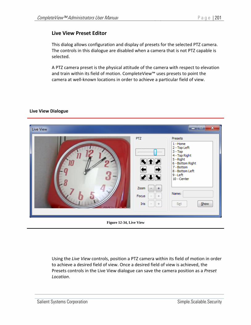
CompleteView™ Administrators User Manual P a g e | 201
Salient Systems Corporation Simple.Scalable.Security
Live View Preset Editor
This dialog allows configuration and display of presets for the selected PTZ camera. The controls in this dialogue are disabled when a camera that is not PTZ capable is selected.
A PTZ camera preset is the physical attitude of the camera with respect to elevation and train within its field of motion. CompleteView™ uses presets to point the camera at well‐known locations in order to achieve a particular field of view.
Live View Dialogue
Figure 12-34, Live View
Using the Live View controls, position a PTZ camera within its field of motion in order to achieve a desired field of view. Once a desired field of view is achieved, the Presets controls in the Live View dialogue can save the camera position as a Preset Location.

CompleteView™ Administrators User Manual P a g e | 202
Salient Systems Corporation Simple.Scalable.Security
Live View PTZ Controls
PTZ Slider Control Adjust the velocity of PTZ camera movements
PTZ Direction Buttons Move the camera field of view in the indicated direction
Zoom Control zoom for mechanical and digital PTZ cameras
Focus Manual focus control for mechanical PTZ cameras
Ins Manual iris control for mechanical PTZ cameras
Table 12‐39, Live View PTZ Controls
Live View Presets Controls
Presets List List of existing presets by preset ID number and name
Presets Name Enter the desired name of the preset, select the number to which the name will correspond, set the camera, click Set. (Note: Name is only configurable for mechanical PTZ cameras.)
Show Show presets for the camera being configured
Set Set the current camera position (and name, if applicable) as a preset location
Table 12‐40, Live View Presets Controls

CompleteView™ Administrators User Manual P a g e | 203
Salient Systems Corporation Simple.Scalable.Security
Cameras, Audio Window
The camera configuration <Audio> window enables a system audio source to be associated with the video stream from the camera being configured.
Start>All Programs>CompleteView>System Configuration>Configure Servers>Cameras>{Camera}>Audio
Figure 12‐35, Cameras Audio Window
Camera Audio Settings
Enable Audio Enable audio stream association
Audio Source Specify the audio source
Channel Select left or right audio channel
Table 12‐41, Camera Audio Settings

CompleteView™ Administrators User Manual P a g e | 204
Salient Systems Corporation Simple.Scalable.Security
The Enable Audio checkbox enables CompleteView™ to associate an audio stream with the video stream from the camera being configured.
The Audio Source drop down menu specifies the audio device or stream to associate with the video stream from the camera being configured.
The Channel radio buttons assign either the left or the right channel from the selected audio source to the video stream from the camera being configured.
An Audio Feature Key is required to enable camera audio.

CompleteView™ Administrators User Manual P a g e | 205
Salient Systems Corporation Simple.Scalable.Security
Cameras, Email Window
CompleteView™ can deliver email notifications to one or more recipients when certain alarm events occur. This is configurable on a per‐camera basis.
An email server must be configured in the Server Configuration <Email> window in order for camera alarm emails to be delivered.
The camera configuration <Email> window determines which alarm events will cause an email to be transmitted and specifies the content of transmitted emails.
Start>All Programs>CompleteView>System Configuration>Configure Servers>Cameras>{Camera}>Email
Figure 12‐36, Cameras Email Window

CompleteView™ Administrators User Manual P a g e | 206
Salient Systems Corporation Simple.Scalable.Security
Email Settings
Send Email on Select notification event
Enable Email Notifications Enable email notifications
Include Snapshot Include .jpeg still image as attachment
Email Subject Email Notification Subject Line
Recipients Recipient List
Apply to All Cameras Applies the settings to all cameras
Table 12‐42, Email Settings
The Send Email on dropdown list selects the event for which to configure an email notification. Once configured, CompleteView™ transmits email notifications for each event occurrence. Email notifications may be configured for multiple events.
Notification Events include:
Sync Loss: When CompleteView™ detects a loss of video signal, the server generates a notification email with an optional JPEG still image file attachment. By default, the JPEG still image is taken from the start of the event.
External Alarm: When an external alarm event occurs, the server generates a notification email with an optional JPEG still image file attachment. By default, the JPEG still image is taken from the start of the event.
Motion Detected: When a motion detected event occurs, the server generates a notification email with an optional JPEG still image file attachment. By default, the JPEG still image is taken from the start of the event.
Sync Gained: Following a Sync Lost event, when CompleteView™ reconnects to the camera, the server generates a notification email with an optional JPEG still image file attachment. By default, the JPEG still image is taken from the start of the event.
Recording Failed: If a recording fails to be written to a camera volume, an email notification is sent.
The Email Notifications Enabled checkbox configures CompleteView™ to transmit email notifications.

CompleteView™ Administrators User Manual P a g e | 207
Salient Systems Corporation Simple.Scalable.Security
The Include Snapshot checkbox configures CompleteView™ to include a JPEG still image as a file attachment to the notification email. Each 320 x 240 JPEG still image is approximately 10KB in size.
The Delay before Taking Snapshot control specifies a delay period, in seconds, after the alarm has triggered before taking the snapshot.
The Email Subject text box specifies the notification email header, subject line.
The Recipients text box specifies Internet format email addresses of the persons who should receive the notification. Include multiple recipients by separating the email addresses with a comma.
Email Notification Limits Settings
Maximum Emails Enable and specify the max quantity emails sent per occurrence
Minimum Interval Between Emails
Enable and specify the minimum interval between emails sent per occurrence
Delay Prior to Sending Enable and specify time delay between event and email
Only After Enable and select Event Type limitation
Table 12‐43, Email Notification Limits
The Maximum Emails checkbox and spinner control enables and specifies a limit on the quantity of email notifications sent per event occurrence. Check the Maximum Emails checkbox to enable the email quantity limit and specify the maximum quantity using the maximum quantity, spinner control.
The Minimum Interval between Emails checkbox and text box enables and specifies a minimum delay between email notifications when multiple emails are sent per event occurrence. Check the Maximum Interval checkbox to enable the delay and specify the delay in seconds in the textbox.

CompleteView™ Administrators User Manual P a g e | 208
Salient Systems Corporation Simple.Scalable.Security
The Delay Prior to Sending Email checkbox and text box enables and specifies the time emails are sent, in seconds, from the chosen event to the configured recipients.
The Only After checkbox and dropdown menu enables and specifies what type of event prompts an email. Select either External Alarm or Motion detected. If left unchecked, either event will trigger an email.
Cameras, Analytics Window
The <Analytics> window contains settings that control CompleteView™ integration with Agent VI analytics.
CompleteView™ can deliver video streams to an integrated Agent VI video analytics system and associate alarm events from the integrated analytics system with alarm recordings.
Start>All Programs>CompleteView>System Configuration>Configure Servers>Cameras>{Camera}>Analytics
Figure 12‐37, Cameras Analytics Window

CompleteView™ Administrators User Manual P a g e | 209
Salient Systems Corporation Simple.Scalable.Security
Analytics Settings
Analyze Video Select this option to have the CompleteView server analyze the video stream and transmit a feature stream to the associated Agent VI server.
Record Alarms Select to record alarm on event notification from the Agent VI server.
External Identifier This number associates a sensor from the Agent VI system to the corresponding camera in CompleteView. Make sure the sensor number configured in Agent VI matches this number.
Table 12‐44, Analytics Settings

CompleteView™ Administrators User Manual P a g e | 210
Salient Systems Corporation Simple.Scalable.Security
Cameras, Edge Storage Window
The <Edge Storage> window enables CompleteView™ integration with edge storage recording on devices that support Edge Storage. CompleteView™ can configure the target devices to record to an internally installed SD card or to a separate Network Attached Storage (NAS) storage device. The device will record its video stream at the same resolution and frame rate configured by the CompleteView™ server.
When a camera stream is interrupted by a network outage or other event, CompleteView™ will retrieve any missing recordings from the camera’s SD card or associated NAS server.
Start>All Programs>CompleteView>System Configuration>Configure Servers>Cameras>{Camera}>Edge Storage
Figure 12‐38, Cameras Edge Storage Window

CompleteView™ Administrators User Manual P a g e | 211
Salient Systems Corporation Simple.Scalable.Security
Edge Storage integration is currently available for use with Axis cameras. The controls in the Edge Storage window are available when an Axis edge storage camera is selected in the CompleteView™ camera configuration <IP> window. Currently, Axis supports only H.264 for Edge Storage, and the SanDisk Extreme is highly recommended for use as the media. NAS drives should be 200Gb or greater, and network latency is a consideration when storing large amounts of video data
Edge Storage Settings
SD Card Storage Options
Format SD Card: Performs a one‐time initial format of the SD card internally installed in the Axis camera.
This option is reset once CompleteView has completed the format. The configuration must be reloaded to see the change

CompleteView™ Administrators User Manual P a g e | 212
Salient Systems Corporation Simple.Scalable.Security
Network Share Storage Options
Hostname or IP: Hostname or IP address of the NAS Server.
Share Path: The UNC pathname to the shared netwrok folder where camera video will be stored.
Username/Password:
Figure 12‐39, Edge Storage Settings
Edge Storage Synchronization Options
Figure 12‐40, Edge Storage Synchronization Options
In order to avoid and minimize network congestion, CompleteView™ can be configured to synchronize camera recordings on a schedule. Remote cameras operating over limited network bandwidth can have their recordings synchronized to CompleteView™ at a time when the network is experiencing less traffic. The synchronization schedule is configured under ‘Synchronization Options’.
1. Run video synchronization at: Set the calendar control to the day on which the first synchronization event is to begin.

CompleteView™ Administrators User Manual P a g e | 213
Salient Systems Corporation Simple.Scalable.Security
2. Using the time control to the right of the calendar control, set the time of day at which the synchronization event should occur.
3. Below the date and time controls, set the frequency by number of days or hours between synchronization events. In the example in the screen shot, the synchronization is set to start on 8/21/2013 and occur at 1am every day.
Advanced Window
The Advanced window contains the Dynamic Frame Throttling and Dynamic Video Decoding enabling checkboxes.

CompleteView™ Administrators User Manual P a g e | 214
Salient Systems Corporation Simple.Scalable.Security
Start>All Programs>CompleteView>System Configuration>Configure Servers>Cameras>{Camera}>Advanced
Figure 12-41, Cameras Advanced tab
Dynamic Frame Throttling
When Dynamic Frame Throttling (DFT) is enabled, CompleteView Server monitors incoming video queue length. When queue length exceeds a certain threshold, DFT engages and processes only key video frames until the queue length is restored to normal levels. This helps reduce video latency, maintain video quality, and reduce CPU load. The frame throttling only affects live video to CompleteView clients. Playback is unaffected, and all video data is available for review. When DFT is applied to a video stream, a start/stop log entry is created, and an overlay is displayed indicating DFT activity.
Dynamic Video Decoding
Dynamic Video Decoding (DVD) monitors which camera feeds are currently being viewed in Live Mode. Feeds that are not being actively viewed are not processed for

CompleteView™ Administrators User Manual P a g e | 215
Salient Systems Corporation Simple.Scalable.Security
live viewing by the server, significantly reducing CPU load. It should be noted that feeds configured for Server Motion Detection, Server Video Analytics, and video feeds pushed to Immix (which is typically a server wide setting) will not enjoy the benefits of DVD, as those functions require constant video stream processing. Some cameras are capable of On‐Camera Motion Detection which does not rely on the CompleteView server for processing, hence they are able to take advantage of DVD. DVD is compatible with approximately 80% of current camera drivers supported by CompleteView, including Generic RTSP drivers.
Max. Latency
The maximum latency field sets the limit of video latency, denoted in seconds, before DFT is applied to the video stream. The Max Number of GOPs must also be reached before DFT is applied.
Max Number of GOPs
The maximum number of GOPs field denotes the maximum number of GOPs (Group of Pictures) buffered before DFT is applied to the video stream. The Max latency must also be reached before DFT is applied.

CompleteView™ Administrators User Manual P a g e | 216
Salient Systems Corporation Simple.Scalable.Security
Audio Devices
The settings in the Audio Devices group of options allows configuration of each audio device independently in a CompleteView™ Server.
Audio Devices, Settings Window
Start>All Programs>CompleteView>System Configuration>Configure Servers>Audio Devices><{Device}>Settings
Figure 12‐42, Audio Devices Settings Tab
Audio Devices Settings
Capture Quality Set audio quality
Channel Mode Specify left/right channel operation
Table 12‐45, Audio Devices Settings

CompleteView™ Administrators User Manual P a g e | 217
Salient Systems Corporation Simple.Scalable.Security
The Capture Quality setting determines the rate at which CompleteView™ samples input analog audio to produce a digital audio stream where:
Low = 8000 Kb/s
Medium = 11,025 Kb/s
High = 22,050 Kb/s
The Channel Mode setting determines how CompleteView™ distributes audio to left and right channels, where:
Mono Directs monophonic audio to a single audio channel
Stereo Directs stereophonic audio to two complementary audio channels
Split‐Channel Directs monophonic audio to two independent audio channels
An Audio Feature Key is required to enable CompleteView™ audio functionality.

CompleteView™ Administrators User Manual P a g e | 218
Salient Systems Corporation Simple.Scalable.Security
Alarm Devices
CompleteView™ is capable of integrating with third party Digital I/O devices. Digital inputs detect, and digital outputs assert, external alarm conditions.
CompleteView™ uses alarm inputs to trigger recordings from specific cameras.
Alarm outputs from CompleteView™ indicate the occurrence of camera events such as analog camera sync loss or other external events.
Alarm devices can be embedded in IP cameras. They may be stand‐alone network attached devices or directly attached to the CompleteView™ server via a USB port. It is possible to add a single device or any combination of alarm devices to a CompleteView™ server.
For each physical alarm device in the system, there is an alarm device object in the server configuration file, in the Alarm Devices container. Alarm device objects specify the configuration settings and properties of their associated physical devices.
Creating and Managing Alarm Devices
The Alarm Devices Menu enables a system administrator to manage alarm device objects.
This section describes how to manage alarm device objects using the Alarm Devices Menu. Note that the functions available from the Alarm Devices Menu can also be accessed via corresponding buttons in the server Configuration Console Toolbar.
Start>All Programs>CompleteView>System Configuration>Configure Servers>Alarm Devices
Add Alarm Device
Add a new Alarm Device object
Delete Alarm Device
Remove selected Alarm Device object.
Click to select Volume, right click opens menu
Figure 12‐43, Alarm Device Menu
To create a new alarm device object:
CompleteView™ Administrators User Manual P a g e | 219
Salient Systems Corporation Simple.Scalable.Security
1. In the Server Configuration console tree, select the Alarm Devices container and right click to open the Alarm Devices Menu.
2. Mouse over and select Add Alarm Device. A New Alarm dialogue will appear.
3. In the New Alarm dialogue box, enter a name for the alarm device object being created.
4. Click [OK]. The new alarm device object is created in the Alarm Devices container and ready for configuration.
To delete an alarm device object:
1. In the Server Configuration console tree, expand the Alarm Devices container. A list of alarm device objects will appear.
2. Select the alarm device to be deleted, then right click to open the Alarm Devices Menu.
3. Mouse over and click Delete Alarm Device. The selected alarm device object is removed from the server configuration Alarm Devices container.

CompleteView™ Administrators User Manual P a g e | 220
Salient Systems Corporation Simple.Scalable.Security
Configuring Alarm Devices
Alarm Devices, IP Window
The Alarm Devices <IP> window enables a system administrator to configure the network communication parameters associated with the selected alarm device.
The parameters displayed in the <IP> window may change according to the device manufacturer and model.
Start>All Programs>CompleteView>System Configuration>Configure Servers>Alarm Devices><{Device}>IP
Figure 12‐44, Alarm Devices IP Tab

CompleteView™ Administrators User Manual P a g e | 221
Salient Systems Corporation Simple.Scalable.Security
Alarm Device <IP> Settings
Device Model Select manufacturer/model
Address (Hostname/IP) Device IP address or hostname
Username Device username
Password Device password
Timeout Communications attempt timeout
Retries Communications attempt retries
Table 12‐46, Alarm Device IP Settings
The Device Model dropdown menu specifies the manufacturer and model of the alarm device being configured. The parameters displayed and available in all alarm device configuration windows may change depending upon the Device Model selected.
The Address (Hostname/IP) specifies the network IP address or hostname for the selected alarm device, if applicable to the selected Device Model.
The Username text box specifies the username for the device, if applicable to the selected Device Model.
The Password text box specifies the device’s password, if applicable to the selected Device Model.
The Timeout control specifies the time in seconds that CompleteView™ will wait for a response upon communication attempts to the alarm device being configured. Change this setting only at the direction of Salient technical support.

CompleteView™ Administrators User Manual P a g e | 222
Salient Systems Corporation Simple.Scalable.Security
The Retries control specifies the quantity of successive communication attempts CompleteView™ will perform upon timeout. Change this setting only at the direction of Salient tech nical support.
Alarm Devices, Inputs Window
The alarm devices <Inputs> window contains settings that specify the behavior of digital inputs from the alarm device being configured, as well as CompleteView™ behavior upon detecting active alarm inputs.
Depending upon the manufacturer and model of the alarm device being configured, the quantity of available inputs will vary.
Start>All Programs>CompleteView>System Configuration>Configure Servers>Alarm Devices><{Selected Device}>Inputs
Figure 12‐45, Alarm Devices Inputs tab

CompleteView™ Administrators User Manual P a g e | 223
Salient Systems Corporation Simple.Scalable.Security
Alarm Device <Inputs> Settings
Input Select the digital input to configure
Trigger When Closed Select trigger state = closed
Trigger When Open Select trigger state = open
Trigger Recording On Camera Select CompleteView™ response to trigger
Table 12‐47, Alarm Device Inputs Settings
The Input drop down list selects the alarm device digital input to be configured.
Available inputs are configured independently. For each available input, select the input from the input drop down list, then set the desired trigger and recording behaviors.
The Trigger When Closed radio button configures CompleteView™ to detect a trigger condition the alarm device digital input circuit is closed.
The Trigger When Open radio button configures CompleteView™ to detect a trigger condition when the alarm device digital input circuit is open.
The Trigger Recording on Camera list specifies which camera or cameras begin recording when CompleteView™ detects a trigger condition on the input being configured.
By selecting one or more camera inputs, CompleteView will utilize the alarm input to drive video recording. It is important to note that in order for the recording to take place, the External Alarm Recording mode in the Recording Schedule must be enabled. If the input is alarmed, but external alarm recording is not currently active in the recording schedule, then video recording will not occur.

CompleteView™ Administrators User Manual P a g e | 224
Salient Systems Corporation Simple.Scalable.Security
Alarm Devices, Outputs Window
The alarm devices <Outputs> window contains settings that specify CompleteView™ behavior when controlling digital outputs from the alarm device being configured.
Depending upon the manufacturer and model of the alarm device being configured, the quantity of available outputs will vary.
Start>All Programs>CompleteView>System Configuration>Configure Servers>Alarm Devices><{Device}>Outputs
Figure 12‐46, Alarm Devices Outputs Window

CompleteView™ Administrators User Manual P a g e | 225
Salient Systems Corporation Simple.Scalable.Security
Alarm Device <Outputs> Settings
Output Select the digital output to configure.
Name User definable output name
Close When Triggered Select trigger state = closed
Open When Triggered Select trigger state = open
Camera Triggering Output Select the camera triggering the output
Table 12‐48, Alarm Device Inputs Settings
The Output drop down list selects the alarm device digital output to be configured.
The available outputs are configured independently. For each available output, select the output from the drop down list then set the desired trigger and recording behaviors.
The Name field allows a user‐definable name to be given to the alarm being configured. Enter a new name, and click [Update Name].
The Close When Triggered radio button specifies the output state be closed when true.
The Open When Triggered radio button specifies the output state be open when true.
The Camera Triggering Output list specifies the camera or cameras that generate triggers for the output being configured.
Alarm Device Output Triggers
Software Trigger Allows triggering of the output by a Video Client user.
Trigger On External Alarm Set output true upon external alarm
Trigger on Motion Set output true upon camera motion detect
Trigger on Sync Loss Set output true upon camera sync loss
Table 12‐49, Alarm Device Output Triggers

CompleteView™ Administrators User Manual P a g e | 226
Salient Systems Corporation Simple.Scalable.Security
The Software Trigger radio button allows a Video Client user to trigger the desired output from within the camera window. If configured, an icon representing a door, an alarm, or a generic trigger will appear in the upper right hand corner of the camera’s view in the Video Client software. The icon can be clicked to actuate the output.
The Trigger on External Alarm radio button configures CompleteView™ to set the output true upon an external alarm condition.
The Trigger on Motion radio button configures CompleteView™ to set the output true upon camera motion detect.
The Trigger on Sync Loss configures CompleteView™ to set the output true upon camera sync loss.

CompleteView™ Administrators User Manual P a g e | 227
Salient Systems Corporation Simple.Scalable.Security
Serial Ports
Serial ports connect to analog cameras in order to exert Pan, Tilt, and Zoom (PTZ) motion control. CompleteView™ supports PTZ serial communications via the server computer COM1 through COM4 serial ports.
Serial Ports Functional Overview
CompleteView™ supports using the server computer serial ports COM1 through COM4 for PTZ motion control over analog cameras.
Analog cameras employ a variety of connectivity methods and protocols for PTZ control. Always consult the camera manufacturer’s documentation for instructions before installation.
Serial Ports Functional Diagram
Figure 12‐47, Serial Ports Functional Diagram
In general, most analog camera PTZ control serial interfaces conform to some variation of the Electronic Industry Association (EIA) Recommended Standard (RS)
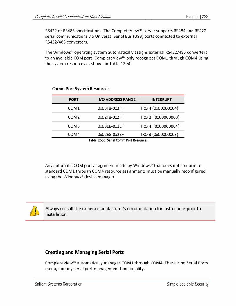
CompleteView™ Administrators User Manual P a g e | 228
Salient Systems Corporation Simple.Scalable.Security
RS422 or RS485 specifications. The CompleteView™ server supports RS484 and RS422 serial communications via Universal Serial Bus (USB) ports connected to external RS422/485 converters.
The Windows® operating system automatically assigns external RS422/485 converters to an available COM port. CompleteView™ only recognizes COM1 through COM4 using the system resources as shown in Table 12‐50.
Comm Port System Resources
PORT I/O ADDRESS RANGE INTERRUPT
COM1 0x03F8‐0x3FF IRQ 4 (0x00000004)
COM2 0x02F8‐0x2FF IRQ 3 (0x00000003)
COM3 0x03E8‐0x3EF IRQ 4 (0x00000004)
COM4 0x02E8‐0x2EF IRQ 3 (0x00000003) Table 12‐50, Serial Comm Port Resources
Any automatic COM port assignment made by Windows® that does not conform to standard COM1 through COM4 resource assignments must be manually reconfigured using the Windows® device manager.
Creating and Managing Serial Ports
CompleteView™ automatically manages COM1 through COM4. There is no Serial Ports menu, nor any serial port management functionality.
Always consult the camera manufacturer’s documentation for instructions prior to installation.

CompleteView™ Administrators User Manual P a g e | 229
Salient Systems Corporation Simple.Scalable.Security
Configuring Serial Ports
Configure Serial Ports by entering the appropriate RS232 serial communications parameters in the Settings window for each port.
To configure a serial port:
1. Expand the Serial Ports container
2. In the configuration utility console tree, select the serial port to be configured. The Settings Window for the selected serial port will appear in the Configuration Window details pane.
3. In the Serial Port Settings Window, input the serial port communications parameters.

CompleteView™ Administrators User Manual P a g e | 230
Salient Systems Corporation Simple.Scalable.Security
Serial Ports Settings Window
The Serial Port Settings Window contains the parameters needed to configure RS‐232 serial communication ports for operation with analog cameras.
Start>All Programs>CompleteView>System Configuration>Configure Servers>Serial Ports><{Port}>Settings
Figure 12‐48, Serial Ports Settings Tab
Serial Port Settings
Baud Rate Specify the symbol‐signaling rate.
Data Bits Specify the quantity of data bits per 8‐bit symbol.
Parity Specify the type of Parity checking.
Stop Bits Specify the quantity of stop‐bits per transmitted symbol.
Flow Control Specify the type of flow control.
Table 12‐51, Serial Port settings

CompleteView™ Administrators User Manual P a g e | 231
Salient Systems Corporation Simple.Scalable.Security
Baud Rate specifies the speed of serial communications between the CompleteView™ server and the USB to RS422/485 converter in bits per second. The default baud rate is 9600 bits per second.
Baud rate options are:
1200 bits per second
2400 bits per second
4800 bits per second
9600 bits per second
14400 bits per second
19200 bits per second
38400 bits per second
57600 bits per second
Data Bits specifies the number of bits used as a data character from each 8‐bit symbol transmitted or received on the serial communications interface. The default setting is for 8‐bit characters.
Typically, this setting will change depending on the use of parity checking. If no parity checking is implemented, data characters are 8‐bits. If odd or even parity checking is implemented, data characters are 7‐bits plus one parity bit.
Data Bit options are:
7‐bit characters
8‐bit characters
Parity specifies the type of parity checking that will be performed against each 8‐bit symbol received on the serial communications interface. The default Parity setting is “none”.
Parity options are:

CompleteView™ Administrators User Manual P a g e | 232
Salient Systems Corporation Simple.Scalable.Security
Odd Parity – the parity bit is set or cleared in order to make the total quantity of ‘1’ bits in the received 8‐bit symbol an odd number.
Even Parity – the parity bit is set or cleared in order to make the total quantity of ‘1’ bits in the received 8‐bit symbol an even number.
None – no parity checking is performed.
Stop Bits specifies the minimum idle time in bit periods after transmitting an 8‐bit symbol on the serial communications interface. The default Stop Bit setting is “1”.
Stop Bit options are:
1‐bit period
1.5‐bit periods
2‐bit periods
Flow Control specifies the type of character flow control implemented on the serial communications interface. The default Flow Control setting is “None”.
Flow Control options are:
Hardware – flow control uses RS232 RTS/CTS hardware signaling.
Software – flow control uses XON/XOFF character signaling.
None – no flow control is used

CompleteView™ Administrators User Manual P a g e | 233
Salient Systems Corporation Simple.Scalable.Security
Video Volumes
A Video Volume is a file system directory where CompleteView™ stores video recorded from cameras:
Volume Objects represent each Video Volume in the server configuration file. Volume Objects contain attributes describing how related physical storage is accessed and managed.
Volume Objects reside in the server configuration file Volumes Container. Every volume object is configured to associate a set of cameras with the Video Volume physical storage where camera video is recorded.
The Volume Object creates a many‐to‐many relationship between cameras and storage; multiple cameras can be associated with a single volume and a single camera can be associated with multiple volumes. Only cameras related to a video volume via a Volume Object can contribute video to that volume.
Video Volume physical storage may exist on a local disk volume, a removable disk volume or on a network share. Local disk Volumes are accessed by using the Microsoft® file‐system pathname format. Volumes on a network share are accessed by using a Universal Naming Convention pathname.
Video Volumes Directory Structure
CompleteView™ Volume Folders:
Folder: “\CV Volume‐A\” == Volume Object: “\\VideoShare\CV Volume‐A”
Folder: “\CV Volume‐B\” == Volume Object: “\\VideoShare\CV Volume‐B”
Each physical CV Volume folder corresponds directly to a server configuration logical Volume Object.
CompleteView™ Volume Camera Sub‐Folders:
Example Directory Structure Legend: “==” read as “corresponds to”
Table 12‐52, Video Volume Directory Structure

CompleteView™ Administrators User Manual P a g e | 234
Salient Systems Corporation Simple.Scalable.Security
The Video Volume directory structure consists of a volume folder, camera sub‐folders and fixed‐length video files:
Volume folders are created by the System Administrator when creating CompleteView™ Video Volumes. To be properly configured, every volume folder must correspond to a logical Volume Object in a Server Configuration. This association is made when Volume Objects are created using the System Configuration Utility.
Camera sub‐folders are created and managed automatically by CompleteView™. For each camera associated with a volume, CompleteView maintains a set of camera sub‐folders within that volume. One sub‐folder is created for each day of camera operation. The quantity of subfolders that can be maintained for each camera is determined by video volume size.
Video files contain video recorded from individual cameras. Camera video is organized into fixed‐length “chunks” where each chunk is stored in sequence, as a file, into its appropriate camera sub‐folder.

CompleteView™ Administrators User Manual P a g e | 235
Salient Systems Corporation Simple.Scalable.Security
Video Volumes Functional Overview
There are five types of CompleteView™ Video Volume:
Regular Storage Volume
Export Storage
Permanent Storage Volume
Archive Only Volume
Backup Only Volume
Regular Storage Volumes are used to store video recorded from cameras
Export Storage Volumes are used as a central repository for exported video clips, and can be used to extract more detailed information about the exported clips.
Permanent Storage Volumes are Read‐Only volumes used to store video.
Archive Only Volumes store aged video that has been automatically moved from associated Regular Storage Volumes.
Backup Only Volumes store aged video automatically copied from associated Regular Storage Volumes.
Regular Storage Volume Operation
A Regular Storage Volume is used to store video recorded from individual cameras. Each Regular Storage Volume is associated with a specific set of cameras. Video is written to a regular storage volume by its associated cameras according to a recording schedule defined for each camera. For more information about recording schedules, refer to Section 0, Schedules.
Within a video volume folder there exists a set of subfolders for each camera associated with that volume. Camera subfolders each contain approximately 24 hours of video recorded from their respective cameras. Within camera subfolders, recorded video is stored sequentially as multiple fixed‐length files of a manageable size to facilitate playback and search functions.
Once camera video has been recorded to a Regular Storage Volume, it can be accessed by CompleteView™ clients via their playback interfaces.

CompleteView™ Administrators User Manual P a g e | 236
Salient Systems Corporation Simple.Scalable.Security
Clients initiate per‐camera searches through storage volumes when requested to playback video. Per‐camera searches are limited to the video contained in volumes having an association with the camera being searched. If a camera is associated with more than one storage volume, video from that camera is stored and can be searched sequentially within a volume and then in a contiguous manner across multiple volumes.
Storage Volumes Functional Diagram
Table 12‐53, Storage Volumes Functional Diagram
As camera video is recorded, the size of a Regular Storage Volume could continue to grow and might outgrow the capacity of the physical disk on which it resides, unless it is carefully managed. If allowed to occur, this would affect the integrity of all volumes residing on the same physical disk.

CompleteView™ Administrators User Manual P a g e | 237
Salient Systems Corporation Simple.Scalable.Security
In order to manage Regular Storage Volume growth, CompleteView™ incorporates Volume management features that include a timed purge of old video records, and a free space threshold purge of video records.
The timed purge occurs when stored video reaches its allotted length of storage time, set in days.
The free space threshold purge occurs when the amount of free space on the volume falls below its set minimum (in MB). When the amount of free space falls below this threshold, CompleteView™ automatically begins deleting the oldest video records on the volume in order to maintain the specified minimum free space on the physical disk.
As video records age, they can be automatically moved from a Regular Storage Volume to an associated Archive Only Volume, or they can be copied from a Regular Storage Volume to an associated Backup Only Volume.
Regular Storage Volume Archive and Backup functions are mutually exclusive.
Moving storage volume records to an Archive Only Volume provides a way to manage the volume size. Copying storage volume records to a Backup Only Volume provides a way to ensure volume content.

CompleteView™ Administrators User Manual P a g e | 238
Salient Systems Corporation Simple.Scalable.Security
Export Storage Volume Operation
An Export Storage volume functions as a central repository for video clips selected for exportation in CompleteView. Creation of Export Storage volumes is optional, and multiple volumes may be created. Advantages of using export volumes are evident in both the exportation process and administratively. During the exportation process, the Video Client user is identified by name and is compelled to provide a description of the export, if configuration is done correctly. In addition, all exportation operations are viewable as recorded video for the specific camera in Admin Console. It should be noted that if multiple export volumes are created and the volume currently in use reaches capacity, new video clips will cascade into the next export volume with available space. If no Export Storage volumes are created, the export to server option will be disabled, and a path in which to save the video will need to be selected.
The Store All Exports and Store Server Export Queue options offer flexible means of documenting Video Client user and description information, based on server configuration and data entered in the Video Client.
If Store All Exports is checked, Store Server Export Queue is automatically selected as well. This configuration will give Video Client users the option to save the clip to a local disk or CD/DVD, but also creates a copy of the exported file on the Export Storage Volume. In addition, Video Client users are compelled to enter a description of the exportation.
If only Store Server Export Queue is selected, Video Client users are given the option to save the file locally, to a CD/DVD, or use the Export Storage volume. If the export volume is selected, users are compelled to enter a description of the clip. If a local disk is selected, no description is required.
If neither Store All Exports nor Store Server Export Queue are selected, Video Client users will not have the option to select the Export Storage volume, but a record of the exportation will be placed in the camera’s recorded video information in Admin Console (only a record of the exportation will be available, not the video itself).
Execute export operation dictates when the exportation and storage of the video clips occurs. Selecting Immediately performs the exportation as soon as all prompts are answered. In some environments, it is advantageous to schedule the exportations during off‐peak times. Select Specific Time and enter the appropriate value to delay exportation until the desired time.

CompleteView™ Administrators User Manual P a g e | 239
Salient Systems Corporation Simple.Scalable.Security
Email Settings allow specific users to be notified when the Export Storage volume is reaching its capacity. Select Send notification email…, enter the value (in MB) of remaining space to serve as a threshold, and enter a comma separated list of emails (or just one). Note that the CompleteView email server must be configured for notifications to be sent. See the Server Configuration, Server Email Window section for more details.
Permanent Storage Volume Operation
CompleteView will find recorded video for the associated cameras on this volume type when a search is initiated through a playback interface. This is used less frequently than Regular Storage and Archive Only volume types. An example of this volume type would be to define the location of video which has been restored from a backup or the location of video moved from Regular Storage by a 3rd party archiving program.
Archive Only Volume Operation
Archive Only Volumes store aged video that has been automatically moved from associated Regular Storage Volumes. Generally, older video is archived in order to maintain free space on storage volume disks. Therefore, whenever possible, Archive Only Volumes and Regular Storage Volumes should exist on separate physical storage media.
Backup Only Volume Operation
Backup Only Volumes store aged video automatically copied from Regular Storage Volumes.
Archive Only or Backup Only Configuration Guidelines
It is strongly recommended that these guidelines be employed for best performance.
Improper configuration of archive or backup video volumes can result in video being unintentionally purged.
1. The Archive Only or Backup Only volume should be on its own partition and not used for any other purpose.
2. Multiple "Regular Storage" volumes should not be configured to archive to the same "Archive Only" or Backup Only volume. Each "Regular Storage"

CompleteView™ Administrators User Manual P a g e | 240
Salient Systems Corporation Simple.Scalable.Security
volume to be archived or backed up should have its own dedicated "Archive Only" or Backup Only volume associated with it.
3. When scheduling archive or backup activity from multiple Regular Storage volumes on a single server, schedule the archive or backup of each volume to occur at separate times. Plan the archive or backup schedule for each Regular Storage volume so that no other volume on the same server will perform an archive or backup simultaneously.
4. Make sure the archive or backup volume is larger than the contents that will be stored on it.
5. Schedule archiving or backup to occur when there will be limited recording on the "Regular Storage" volume and limited network activity. Keep in mind that video may not be available for playback when it is being archived or backed up, and server performance may be affected during the archive or backup event.
Improper configuration of archive or backup video volumes can result in video being unintentionally purged.

CompleteView™ Administrators User Manual P a g e | 241
Salient Systems Corporation Simple.Scalable.Security
Creating and Managing Volumes
Creating CompleteView™ Volumes is a two‐part process. It involves creating a file system directory on a local disk or network share, and then creating corresponding CompleteView™ Volume Objects within the server configuration Volumes Container.
First, create the file system folders where CompleteView™ will store its video volumes. The file‐system directory structure may be organized in any way that suits the local system or network configuration.
Figure 10 41, Video Volume Example Directory
The directory structure must include a folder for each CompleteView™ video volume, and each video volume folder must correspond to a Volume Object in the server configuration.
CompleteView™ video volume folders may exist on local disks or in network shares located anywhere on the network. Wherever they exist, every video volume folder must be assigned a corresponding Volume Object in the CompleteView server configuration. Once video volume folders have been created, use the server configuration utility to create and configure corresponding Volume Objects in the CompleteView™ server configuration.
Example Directory Structure
A CV Volume is created in each sub‐folder

CompleteView™ Administrators User Manual P a g e | 242
Salient Systems Corporation Simple.Scalable.Security
Volumes Menu
The server configuration Volumes Menu enables a system administrator to manage volume objects.
While this section describes how to manage volume objects using the Volumes Menu, note that the functions available from the Volumes Menu can also be accessed via corresponding buttons in the console toolbar.
Start>All Programs>CompleteView>System Configuration>Configure Servers>Volumes><{Volume}
New Volume
Add a new volume object
Delete Volume
Remove a volume object
Move Up Reorder selected volume upward
Move Down Reorder selected volume downward
Click to select Volume, right click opens menu
Figure 12‐49, Volumes Menu
To create a new volume:
1. Create a file system folder to contain the new volume on a physical disk or in a network share.
2. In the Server Configuration console tree, select the Volumes container then right click to open the Volumes Menu.
3. Mouse over and select New Volume. A Browse for Folder dialogue will appear.
4. Using the Browse for Folder dialogue, navigate to and select the folder created in step 1 to contain the New Volume. Click [OK].
5. The New Volume is now created and ready to be configured.

CompleteView™ Administrators User Manual P a g e | 243
Salient Systems Corporation Simple.Scalable.Security
When a new volume is created, a Volume Object is placed in the server configuration Volumes Container. The Volume Object is associated with physical storage where the new video volume resides. The volume object contains attributes that tell the CompleteView™ system what cameras are associated with the volume and how that volume is to be managed.
Once created, a new volume must be configured to ensure it will function as needed. By default, new volumes are configured to function as Regular Storage volumes and have an association with all cameras on the server.
To delete a volume:
1. In the Server Configuration console tree, expand the Volumes container. A list of volumes objects will appear.
2. Select the volume to be deleted, then right click to open the Volumes Menu.
3. Mouse over and click Delete Volume. The selected Volume object is removed from the server configuration Volumes container.
When a volume is deleted, the Volume object is removed from the server configuration Volumes container. However, the file system folder that contains the camera video is not deleted from the disk or network share where it resides. The physical volume remains in the file system but it is no longer recognized by CompleteView™ for the purpose of playback searches or archive and backup functions.
To re‐order volume objects in the volumes container:
1. In the Server Configuration console tree expand the Volumes container. A list of Volumes objects will appear.
2. Select the Volume Object to be moved.
3. Right click the selected Volume Object to open the Volumes Menu, then mouse over and click Move Up or Move Down as desired.
Reordering volume objects in the volumes container has no effect on the way CompleteView™ manages volumes.
CompleteView™ Administrators User Manual P a g e | 244
Salient Systems Corporation Simple.Scalable.Security
Configuring Video Volumes
Configuring a Video Volume involves setting the attributes of a video Volume Object contained in the server configuration Volumes Container.
These attributes can be categorized as follows:
Individual volume association with physical storage
Volume function e.g. type
Management and maintenance behavior for individual volumes
Individual volume association with cameras
Volume attributes are configured through controls contained in the tabbed‐windows pane of the server configuration console. The volume configuration controls are organized into two tabbed‐windows:
The General settings window
The Camera associations window
The General Settings window contains:
Volume management settings
Volume function (type) selection
Volume maintenance settings
The Camera Associations window contains:
Camera association settings

CompleteView™ Administrators User Manual P a g e | 245
Salient Systems Corporation Simple.Scalable.Security
Volume General Settings Window
General Settings Controls
General settings for a video volume are configured through controls contained in the General tabbed‐window that relates to a selected volume.
To access the General setting controls for a volume:
1. In the Server Configuration Console Tree, expand the target Server Configuration and then expand the Volumes Container.
2. Select the target Volume object. The details pane of the server configuration console now displays tabbed windows containing configuration controls for the selected Volume.
3. In the details pane of the server configuration console, click the General tab. The details pane now displays the General settings window relating to the selected volume.
Start>All Programs>CompleteView>System Configuration>Configure Servers>{Server}>Volumes><{Volume}>General
Figure 12‐50, Volumes General Tab

CompleteView™ Administrators User Manual P a g e | 246
Salient Systems Corporation Simple.Scalable.Security
Volume/Database Synchronization
During normal operation, access to specific chunks of video within video volumes is accomplished by reference through a video volume database maintained by CompleteView™. At times, this database is automatically synchronized with the video files in the volume physical storage. The Database Scan Settings let the System Administrator determine if such synchronization should occur whenever the server configuration is updated.
Database Scan Settings
Scan Volume Upon Saving Configuration
Synchronize this volume when server configuration changes.
Scan All Volumes Upon Saving Configuration
Synchronize all volumes when server configuration changes.
Table 12‐54, Database Scan Settings
Scan Volume upon Saving Configuration causes the individual physical volume and the volume database to synchronize whenever the server configuration is updated.
Scan All Volumes upon Saving Configuration causes all physical volumes and the volume database to synchronize whenever the server configuration is updated.
To enable or disable individual Volume/Database synchronization upon configuration changes:
1. In the Database Scan Settings portion of the volume configuration General settings window, mouse over and click to check or un‐check the Scan Volume Upon Saving checkbox, where:
Checked = Enabled
Un‐checked = Disabled
To enable or disable all Volume/Database synchronization upon configuration changes:
1. In the Database Scan Settings portion of the volume configuration General settings window, mouse over and click to check or un‐check the Scan All Volume Upon Saving checkbox, where:

CompleteView™ Administrators User Manual P a g e | 247
Salient Systems Corporation Simple.Scalable.Security
Checked = Enabled
Un‐checked = Disabled
Volume Type Selection
Volume Type Settings
Regular Storage Volume functions as read /write video storage
Export Storage Volume functions as repository for exported video
Permanent Storage
Volume functions as read only video storage
Archive Only Volume contains aged video moved from a Regular Storage volume
Backup Only Volume contains aged video copied from a Regular Storage volume
Table 12‐55, Volume Type Settings

CompleteView™ Administrators User Manual P a g e | 248
Salient Systems Corporation Simple.Scalable.Security
Volume Management Settings
Volume Management Settings
Path Specifies the file system path to video volume folder
Free Space Threshold for Writing
Free‐space video purge threshold
Keep video for days Timed video purge threshold
Begin Removal At Time of day to perform timed purge
Enable Archive Enable archive for this volume
Enable Backup Enable backup for this volume
Table 12‐56, Volume Management Settings
Path specifies the pathname to the Video Volume folder that corresponds with the Video Volume object currently being configured.
To specify a Path:
1. Type the destination pathname into the Path textbox
‐ OR ‐
1. Click the […] button, a Browse for Folder dialogue will appear.
2. Using the Browse for Folder dialogue, navigate to the destination Video Volume folder and click to select.
3. In the Browse for Folder dialogue, click [OK].
4. The Path textbox updates to display the destination folder pathname.
Free Space Threshold for Writing (MB) specifies the point at which disk‐full purges occur in a video volume.
When the amount of available disk space falls below this threshold a volume will be treated as full and video will be purged from that volume using a first‐in‐first‐out mechanism. As a camera attempts to write to a full volume the oldest recorded video from that camera, more than one day old, is purged the volume to free up disk space for new video.

CompleteView™ Administrators User Manual P a g e | 249
Salient Systems Corporation Simple.Scalable.Security
When a Free Space Threshold purge occurs approximately 24 hours of video relative to a specific camera is deleted.
To specify the Free Space Threshold:
1. Into the Free Space Threshold textbox, Type the minimum required disk space in Megabytes (MB).
Keep Video for Days enables timed purges from a video volume, specifies the time in days, that video must age before being purged and sets the time of day that purges will occur.
To specify timed purges:
1. Select the Keep Video For checkbox. This enables the timed purge function. Use the up/down carat in the associated numeric textbox, set the minimum number of days video must age before being purged.
2. Set the Begin Removal at time using the up/down carat in the associated numeric textbox.
Enable Archive enables archiving of video from the current volume. When video is archived, it is moved from the source Storage Volume to a destination Archive Volume. Archived video is purged from the source volume. A Storage Volume may be enabled for either archiving or enabled for backup but cannot be enabled for both.
To enable archiving for a volume:
1. Ensure the Enable Backup checkbox is unchecked.
2. Click to check the Enable Archive checkbox. The Enable Archive settings will appear in the lower portion of the General Settings Window.
3. Configure the Archive Settings.

CompleteView™ Administrators User Manual P a g e | 250
Salient Systems Corporation Simple.Scalable.Security
Volume Archive Configuration
Archive Settings
Archive Video to this Volume
Specify destination archive volume
Keep Local Video For Specify backup video age threshold
Begin Archive At Specify time of day to search for and backup aged video
Archive Video Every Specify frequency in days to search for and backup aged video
Start Today Begin backup operations today
Only Move Video Recorded As…
Filter aged video to be backed up
Table 12‐56, Archive Settings
Archive Video to this Volume specifies the destination Archive Volume for video archived from the Storage Volume being configured.
To specify the destination Archive Volume:
1. Click the archive volume drop‐down menu carat to open archive volume menu. A menu list of available archive volumes will appear.
2. Mouse over and select a destination archive volume.
Keep Local Video For (days) specifies the minimum age threshold for video to be archived and the time of day at which archiving will occur.
The minimum age threshold for video to be archived is the minimum length of time in days that video must age in the Storage Volume before being moved to the specified Archive Volume.
To specify the minimum age threshold:
1. Set the Keep Local Video For (days) threshold using the up/down carat in the associated numeric textbox.
2. Set the Begin Archive time using the Up/Down carat in the associated numeric textbox.
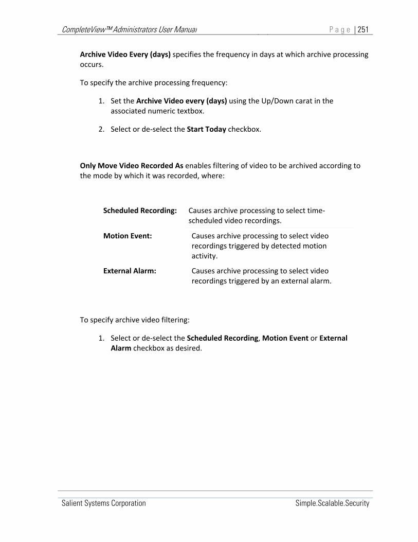
CompleteView™ Administrators User Manual P a g e | 251
Salient Systems Corporation Simple.Scalable.Security
Archive Video Every (days) specifies the frequency in days at which archive processing occurs.
To specify the archive processing frequency:
1. Set the Archive Video every (days) using the Up/Down carat in the associated numeric textbox.
2. Select or de‐select the Start Today checkbox.
Only Move Video Recorded As enables filtering of video to be archived according to the mode by which it was recorded, where:
Scheduled Recording: Causes archive processing to select time‐scheduled video recordings.
Motion Event: Causes archive processing to select video recordings triggered by detected motion activity.
External Alarm: Causes archive processing to select video recordings triggered by an external alarm.
To specify archive video filtering:
1. Select or de‐select the Scheduled Recording, Motion Event or External Alarm checkbox as desired.

CompleteView™ Administrators User Manual P a g e | 252
Salient Systems Corporation Simple.Scalable.Security
Volume Backup Configuration
Enable Backup enables backup of video from the volume being configured. When video is backed up, it is copied from the source Storage Volume to a destination Backup Volume. Video in source volume remains. A Storage Volume may be enabled for either backup or enabled for archiving but cannot be enabled for both.
To enable archiving for a volume:
1. Ensure the Enable Archive checkbox is unchecked.
2. Click to check the Enable Backup checkbox. The Backup settings will appear in the lower portion of the General Settings Window.
3. Configure the Backup Settings.
Backup Settings
Backup Video to this Volume
Specify destination backup volume
Backup Video Older Than
Specify backup video age threshold
Begin Backup At Specify time of day to search for and backup aged video
Backup Video Every Specify frequency in days to search for and backup aged video
Start Today Begin backup operations today
Only Move Video Recorded As…
Filter aged video to be backed up
Table 12‐57, Backup Settings
Backup Video to this Volume specifies the destination Backup Volume for video backed‐up from the Storage Volume being configured.
To specify the destination Backup Volume:
1. Click the archive volume drop‐down menu carat to open archive volume menu. A menu list of available archive volumes will appear.
2. Mouse over and select a destination backup volume.
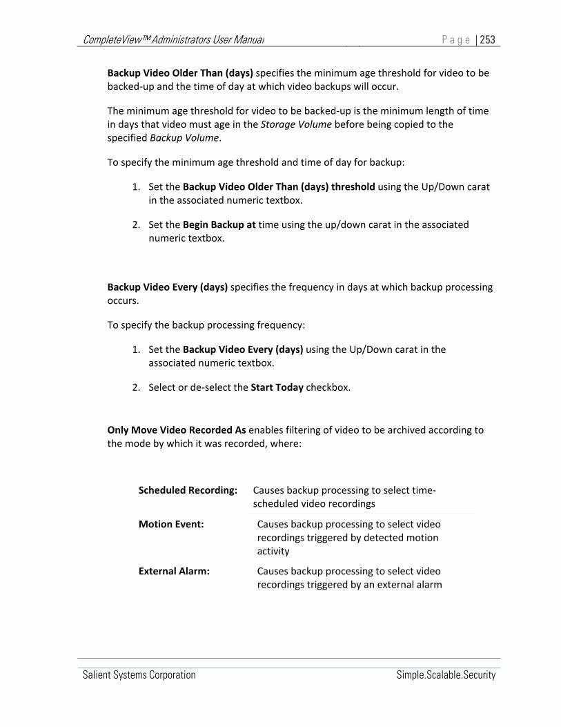
CompleteView™ Administrators User Manual P a g e | 253
Salient Systems Corporation Simple.Scalable.Security
Backup Video Older Than (days) specifies the minimum age threshold for video to be backed‐up and the time of day at which video backups will occur.
The minimum age threshold for video to be backed‐up is the minimum length of time in days that video must age in the Storage Volume before being copied to the specified Backup Volume.
To specify the minimum age threshold and time of day for backup:
1. Set the Backup Video Older Than (days) threshold using the Up/Down carat in the associated numeric textbox.
2. Set the Begin Backup at time using the up/down carat in the associated numeric textbox.
Backup Video Every (days) specifies the frequency in days at which backup processing occurs.
To specify the backup processing frequency:
1. Set the Backup Video Every (days) using the Up/Down carat in the associated numeric textbox.
2. Select or de‐select the Start Today checkbox.
Only Move Video Recorded As enables filtering of video to be archived according to the mode by which it was recorded, where:
Scheduled Recording: Causes backup processing to select time‐scheduled video recordings
Motion Event: Causes backup processing to select video recordings triggered by detected motion activity
External Alarm: Causes backup processing to select video recordings triggered by an external alarm

CompleteView™ Administrators User Manual P a g e | 254
Salient Systems Corporation Simple.Scalable.Security
To specify archive video filtering:
1. Select or de‐select the Scheduled Recording, Motion Event or External Alarm checkbox as desired.

CompleteView™ Administrators User Manual P a g e | 255
Salient Systems Corporation Simple.Scalable.Security
Volumes, Camera Associations Window
Camera Associations configuration applies to Regular Storage volumes and Permanent Storage volumes.
Association to a Regular Storage volume permits camera video read/write access to the volume; the associated camera may record video to the volume and playback controls may retrieve that cameras video from the volume.
Association to a Permanent Storage volume permits read‐only access; the associated camera may not record any new video to the volume, but playback controls can retrieve that cameras previously recorded video from the volume.
Cameras may be associated with multiple volumes.
When recorded to multiple volumes, camera video will, from its earliest record, be written sequentially within a volume and then contiguously across all associated volumes.
Conversely, when playing back video that was recorded across multiple volumes, playback controls read camera video from its earliest record sequentially within a volume and then contiguously across all associated volumes.
Camera Association Controls
Camera associations for a video volume are configured through controls contained in the Cameras tabbed‐window that relates to a selected volume.
To access the camera association controls for a volume:
1. In the server‐configuration console tree, expand the target Server Configuration, and then expand the Volumes Container.
2. Select the target Regular Storage or Permanent Storage Volume object. The details pane of the server configuration console now displays tabbed windows containing configuration controls for the selected Volume.
3. In the details pane of the server configuration console, click the Cameras tab. The details pane now displays the Camera association window relating to the selected volume.

CompleteView™ Administrators User Manual P a g e | 256
Salient Systems Corporation Simple.Scalable.Security
Start>All Programs>CompleteView>System Configuration>Configure Servers>Volumes><{Volume}>Cameras
Figure 12‐51, Volumes Cameras Tab
Cameras Controls
Cameras Enumeration of all configured cameras
Select All Provides one‐click selection of all configured cameras
Table 12‐58, Cameras Controls
The Cameras scroll box lists all cameras and QuickTrack cameras available for association with the video volume being configured. In the scroll box, cameras are listed by name alongside a corresponding checkbox control.
The Select All checkbox selects all listed cameras for association with the volume being configured. Likewise, when this control transitions from selected to unselected all camera associations are cleared.

CompleteView™ Administrators User Manual P a g e | 257
Salient Systems Corporation Simple.Scalable.Security
To select a camera for association:
1. In the Cameras list scroll box, mouse over and click to check the Camera Checkbox corresponding to the associated camera.
To de‐select a camera for association:
1. In the Cameras list scroll box, mouse over and click to clear the Camera Checkbox corresponding to the associated camera.
To select all cameras for association:
1. Mouse over and click to check the Select All checkbox.
To de‐select all cameras for association:
1. Mouse over and click to clear the Select All checkbox.

CompleteView™ Administrators User Manual P a g e | 258
Salient Systems Corporation Simple.Scalable.Security
Schedules
Recording Schedules control the way video from cameras is recorded to Video Volumes.
Schedules Functional Overview
Pre‐defined schedules determine when and how video is recorded from individual cameras.
Once a camera is initialized, it provides a video stream that is constantly available to CompleteView™ servers. The camera video stream is only recorded to a video volume by servers according to the cameras pre‐defined schedule.
CompleteView™ Servers support four types of recording schedule as shown in Table 12‐59, below.
Schedules
Every Day The default schedule established for all cameras.
Weekend The weekend schedule established for all cameras.
Weekday The weekday schedule established for all cameras.
Date A schedule defined for all cameras on a particular day.
Table 12‐59, Schedules
The four schedule types determine how camera video is recorded over calendar time. Each server can provide one “Every Day” schedule, one “Weekend” schedule, one “Weekday” schedule and multiple “Date” schedules.
During configuration, individual cameras can be added to an Every Day, Weekend, Weekday or Date schedule by defining hourly‐ and event‐based recording parameters within that schedule for each camera to be included.
The calendar schedules are prioritized where:
The “Everyday” schedule runs every day of the week and has the lowest priority. This is the default or catchall schedule available to cameras when no higher priority schedule exists.

CompleteView™ Administrators User Manual P a g e | 259
Salient Systems Corporation Simple.Scalable.Security
The “Weekday” schedule runs Monday through Friday. The weekday schedule will always override any conflicting “Everyday” schedule defined for a camera.
The “Weekend” schedule runs every Saturday and Sunday. The weekend schedule will always override any conflicting “Everyday” schedule defined for a camera.
“Date” schedules run on only on the selected date and have the highest priority. Date schedules will always override any conflicting “Everyday,” “Weekday” or “Weekend” schedule defined for a camera.
Calendar schedules are prioritized where:
The Everyday schedule has the lowest priority.
The Weekday and Weekend schedules override the Everyday schedule.
Date schedules override Weekday, Weekend and Everyday schedules.

CompleteView™ Administrators User Manual P a g e | 260
Salient Systems Corporation Simple.Scalable.Security
Creating and Managing Schedules
Schedules are located in the server configuration, Schedules container. Schedules can be managed using functions available on the Schedules Menu.
Schedules Menu
The server configuration Schedules Menu enables a system administrator to manage schedule objects.
While this section describes how to manage schedule objects using the Schedules Menu, note that the functions available from the Schedules Menu can also be accessed via corresponding buttons in the server configuration toolbar.
Start>All Programs>CompleteView>System Configuration>Configure Servers>Schedules><{Schedule}
New Schedule
Add a new schedule object
Clone Schedule
Copy a schedule object
Delete Schedule
Remove selected schedule object.
Click to select Volume, right click opens menu
Figure 12‐52, Schedules Menu
To create a new schedule object:
1. In the Server Configuration console tree, select the Schedules container then right click to open the Schedules Menu.
2. Mouse over and select New Schedule. A Schedule Type dialogue will appear.

CompleteView™ Administrators User Manual P a g e | 261
Salient Systems Corporation Simple.Scalable.Security
Schedule Type Dialogue
Select the type of schedule being created
Table 12‐60, Schedule Dialogue
3. In the Schedule Type dialogue box, use the radio buttons to select the type of schedule being created.
If the schedule type selected is Date, specify the date on which the schedule is to be run.
4. Click [OK]. The new schedule object will be created in the schedules container and ready for configuration.
If a schedule of the specified type already exists, an error dialogue will appear:
Schedule Error Dialogue
Select [Yes] to edit, [No] to replace the existing schedule.
Figure 12‐53, Schedule Error Dialogue
To clone an existing schedule object:

CompleteView™ Administrators User Manual P a g e | 262
Salient Systems Corporation Simple.Scalable.Security
1. In the Server Configuration console tree , select the schedule to be cloned then right click to open the Schedules Menu.
2. Mouse over and select Clone Schedule. A Schedule Type dialogue will appear.
Schedule Type Dialogue
Select the type of schedule being created
Figure 12‐54, Schedule Type Dialogue
3. In the Schedule Type dialogue box, use the radio buttons to select the type of schedule being created.
If the schedule type selected is Date, specify the date on which the schedule is to be run.
4. Click [OK]. The selected schedule will be copied to a new schedule object. The new schedule object will be created in the schedules container and ready for configuration.
If a schedule of the specified type already exists, an error dialogue will appear:

CompleteView™ Administrators User Manual P a g e | 263
Salient Systems Corporation Simple.Scalable.Security
Schedule Error Dialogue
Select [Yes] to edit, [No] to replace the existing schedule.
Table 12‐61, Schedule Error Dialogue
To delete a schedule:
1. In the Server Configuration console tree, expand the Schedules container. A list of schedule objects will appear.
2. Select the schedule to be deleted, then right click to open the Volumes Menu.
3. Mouse over and click Delete Schedule. The selected schedule object is removed from the server configuration Schedules container.

CompleteView™ Administrators User Manual P a g e | 264
Salient Systems Corporation Simple.Scalable.Security
Configuring Schedules
Configuring Schedules involves establishing 24‐hour recording plans for each camera as part of an Everyday, Weekday, Weekend, or Date calendar‐schedule.
Conflicts arising from cameras belonging to multiple calendar‐schedules are resolved according to schedule priorities where:
The Everyday schedule has the lowest priority.
The Weekday and Weekend schedules override the Everyday schedule.
Date schedules override Weekday, Weekend and Everyday schedules.
Configure Schedules by entering a recording plan for each camera into the schedule being configured.
To configure a schedule:
1. In the configuration utility console tree: expand the Schedules container
2. Select the schedule to be configured. The Edit Window for the selected calendar‐schedule will appear in the Configuration Utility details pane.
3. In the Schedules Edit Window, define a 24‐hour recording plan for each camera to participate in the currently selected calendar‐schedule.

CompleteView™ Administrators User Manual P a g e | 265
Salient Systems Corporation Simple.Scalable.Security
Schedules, Edit Window
The Schedules Edit Window provides controls that enable creating and editing a 24‐hour recording plan for each camera.
Recording plans can be created or edited manually, using the Edit Window manual controls, or they may be edited graphically using the recording plan timescale control associated with each camera.
Start>All Programs>CompleteView>System Configuration>Configure Servers>Schedules><{Selected Schedule}>Edit
Figure 12‐55, Schedules Edit Window
Edit Window controls are organized into several groups:
The Camera List
Recording Mode Buttons
Recording Plan Timescale Control
Manual Editing Controls

CompleteView™ Administrators User Manual P a g e | 266
Salient Systems Corporation Simple.Scalable.Security
The Cameras List enumerates all cameras configured on the server. Each camera in the list is associated with a radio button used to select an individual camera and a timescale/slider control. The 24‐hour timescale is a graphical representation of the individual recording plan that repeats daily for the selected camera. A system mouse or other pointing device may be used to select periods within the 24‐hour timescale during which different recording modes can be applied.
Recording Mode Buttons toggle recording mode selection on or off. Once recording modes are selected, they will be applied to the next time‐period specified within the selected cameras 24‐hour recording plan.
Multiple recording modes may be selected to occur simultaneously. External Alarm and Motion recording may be selected in any combination with Scheduled mode, or, in any combination with Pre‐alarm mode.
Pre‐alarm mode and Scheduled mode recording are mutually exclusive.
Recording Mode, Buttons
Scheduled Enables continuous mode recording
Ext. Alarm Enables recording upon external alarm event
Motion Enables recording upon motion detected event
Pre‐Alarm Enables pre‐alarm recording
Erase De‐select any selected recording mode buttons
Table 12‐62, Recording Mode Buttons
Scheduled Mode provides a continuous video recording for the duration of the time‐period(s) specified in the 24‐hour recording plan associated with the selected camera. Multiple Scheduled mode recording periods may exist within a single 24‐period.
A 24‐hour recording plan may specify Scheduled Mode recordings to occur simultaneously with External Alarm or Motion recording.
Ext. Alarm Mode provides video recordings triggered by an external signal input to the selected camera. The post‐alarm duration of Alarm Mode recordings is configurable in

CompleteView™ Administrators User Manual P a g e | 267
Salient Systems Corporation Simple.Scalable.Security
the Camera Configuration Motion/Alarm window. Refer to Section 0, “Cameras, Motion/Alarm Window” for more information.
Motion Mode provides video recordings triggered by motion detected within a predefined zone, within a cameras field of view. The predefined zones and post‐ event duration of Motion recordings are user‐configurable in the Camera Configuration Motion/Alarm window. Refer to Section 0, “Cameras, Motion/Alarm Window” for more information.
Pre‐alarm Mode provides pre‐event video recording when enabled simultaneously with Motion triggered or External Alarm triggered recording. The pre‐event duration of Pre‐Alarm Mode recordings is user‐configurable in the Camera Configuration Motion/Alarm window. Refer to Section 0, “Cameras, Motion/Alarm Window” for more information.
Erase de‐selects any previously selected recording mode buttons.
Manual Editing Controls enable the system administrator to specify and edit recording periods and recording modes within the 24‐hour recording plan for the selected camera.
Start Control Manually sets the start time for a recording period.
End Control Manually sets the end time for a recording period.
Insert Button Insert a recording period into the recording plan for the currently selected camera.
Copy Schedule Button Copy the recording plan from the currently selected camera.
Paste Schedule Button Paste a recording plan to the currently selected camera.
Remove Selected Button
Delete the recording plan from the currently selected camera.
Schedule Window Display a list of recording periods within the recording plan for the currently selected camera.
Table 12‐63, Schedule Manual Editing Controls
Pre‐alarm and Scheduled recording modes cannot be selected simultaneously. When pre‐alarm recording is enabled, scheduled recording is automatically disabled. Simultaneously selecting Motion Mode or External Alarm Mode, and scheduled recording, will automatically disable pre‐alarm recording.

CompleteView™ Administrators User Manual P a g e | 268
Salient Systems Corporation Simple.Scalable.Security
The Schedule window lists the recording periods that occur during a 24‐hour recording plan. Each recording period is associated with one or more recording modes. When a recording period is associated with multiple recording modes the Schedule window lists the same period, once for each mode.
Figure 12‐56, Schedules Manual Edit Controls

CompleteView™ Administrators User Manual P a g e | 269
Salient Systems Corporation Simple.Scalable.Security
Schedule window entries are formatted into three columns as follows:
Recording Mode Start Time End Time
S 00:00 23:59
The Recording Mode column indicates the recording mode that is active for the period specified by Start Time and End Time, where:
S = Scheduled Recording Mode
A =External Alarm Recording Mode
M = Motion Alarm Recording Mode
P = Pre‐Alarm Recording Mode
The Start Time column indicates the period start time.
The End Time column indicates the period end time.
The periods and recording modes listed in the Schedule window are also depicted graphically along the timescale control associated with the selected camera/recording plan.

CompleteView™ Administrators User Manual P a g e | 270
Salient Systems Corporation Simple.Scalable.Security
To manually create a recording period within a recording plan
1. Use the Recording Mode Buttons to select the recording mode/modes that will apply to the period being created.
2. Use the Start control to specify the period begin time.
3. Use the End control to specify the period end time.
4. Click the [Insert>>] button.
Upon clicking [Insert>>], an entry is created in the Schedule window specifying the Start and End time for each recording mode selected.
The newly created period(s) will also be depicted graphically along the timescale control associated with the selected camera/recording plan.
To manually delete a recording period from within a recording plan
1. In the Schedule window, select the period entry to be deleted.
2. Click the [Remove Selected] button.
The selected period is removed from the Schedule window and the graphical timescale control associated with the selected camera/recording plan is updated.
To manually copy a recording plan
An entire Recording Plan may be copied from one camera and pasted to another.
1. In the Camera list, select the radio button associated with camera/recording plan to be copied.
2. Click the [Copy Schedule] button.
3. In the Camera list, select the radio button associated with camera that will receive the copied recording plan.
4. Click the [Paste Schedule] button.
Upon clicking [Paste Schedule], the copied recording plan is pasted to the selected camera.

CompleteView™ Administrators User Manual P a g e | 271
Salient Systems Corporation Simple.Scalable.Security
Recording Plan Timescale Controls
Each camera in the Camera List is associated with a Timescale control. The timescale control graphically depicts and enables graphical editing of a cameras 24‐hour recording plan.
Figure 12‐57, Recording Plan Timescale Control
The timescale control illustrates the 24‐hour timeline on a scale of 0 to 24 in 15‐minute, 30‐minute and 1‐hour increments.
Periods and recording modes within the 24‐hour timeline are depicted as horizontal colored bars where:
Green = Scheduled Recording Mode
Yellow = External Alarm Recording Mode
Red = Motion Alarm Recording Mode
Cyan = Pre‐Alarm Recording Mode
The periods and recording modes depicted along the Timescale are also listed in the Schedule window associated with the selected camera/recording plan.

CompleteView™ Administrators User Manual P a g e | 272
Salient Systems Corporation Simple.Scalable.Security
To create a recording period using the Timescale control
1. Use the Recording Mode Buttons to select the recording mode/modes that will apply to the period being created.
2. Click and drag along the timescale where the recording period is to be created.
A recording period is created within the 24‐hour timescale after the desired time is selected. The recording period is illustrated as one or more colored horizontal bars where, one bar is created for each recording mode applied to the recording period.
To delete a recording period using the Timescale control
1. From the Recording Mode Buttons, select the [Erase] button. All recording mode buttons will become de‐selected.
2. Click and drag along the timescale where the recording period is to be deleted.
Any recording periods along the path of the mouse‐pointer will be deleted after selection.
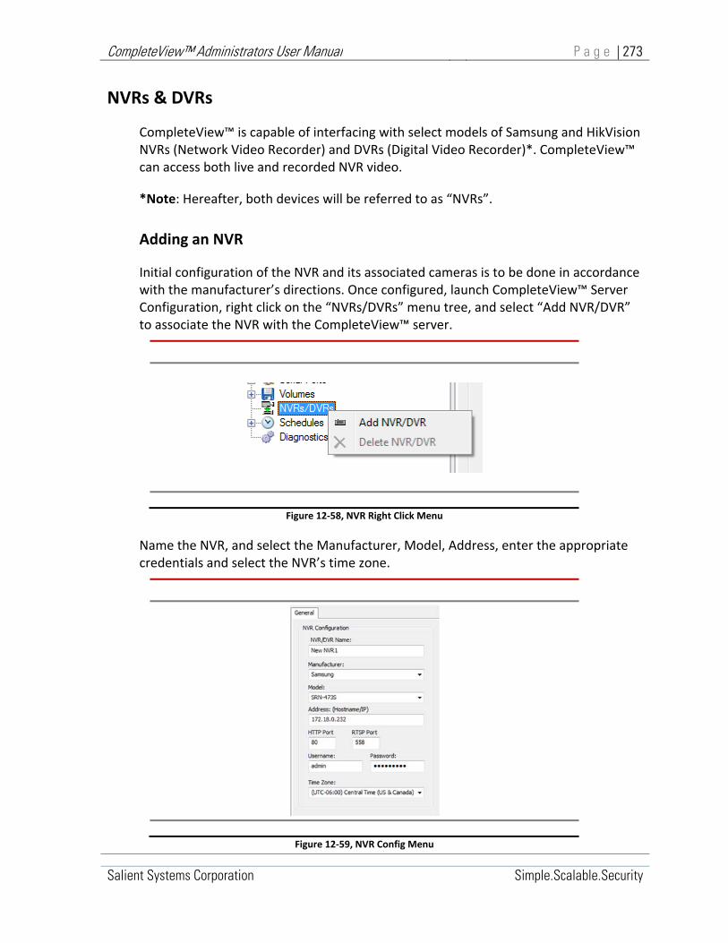
CompleteView™ Administrators User Manual P a g e | 273
Salient Systems Corporation Simple.Scalable.Security
NVRs & DVRs
CompleteView™ is capable of interfacing with select models of Samsung and HikVision NVRs (Network Video Recorder) and DVRs (Digital Video Recorder)*. CompleteView™ can access both live and recorded NVR video.
*Note: Hereafter, both devices will be referred to as “NVRs”.
Adding an NVR
Initial configuration of the NVR and its associated cameras is to be done in accordance with the manufacturer’s directions. Once configured, launch CompleteView™ Server Configuration, right click on the “NVRs/DVRs” menu tree, and select “Add NVR/DVR” to associate the NVR with the CompleteView™ server.
Figure 12‐58, NVR Right Click Menu
Name the NVR, and select the Manufacturer, Model, Address, enter the appropriate credentials and select the NVR’s time zone.
Figure 12‐59, NVR Config Menu

CompleteView™ Administrators User Manual P a g e | 274
Salient Systems Corporation Simple.Scalable.Security
Note that the number of accessible channels for certain models of NVR are limited. The limitations are reflected in the number of available cameras assignable to a given NVR.
Figure 12‐60, NVR General Tab
Adding Cameras to an NVR
After successfully configuring the NVR, adding cameras works similarly to adding non‐NVR cameras in CompleteView™. In Server Configuration, right click on “Cameras,” select “Add Camera”, and enter a meaningful name.
Select the make of the camera from the Manufacturer dropdown (which will be the same make as the NVR that was just added), then select the model of the NVR from the Model dropdown.
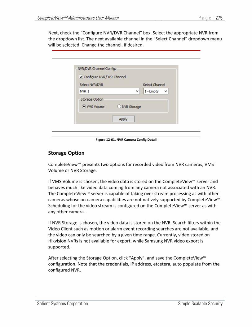
CompleteView™ Administrators User Manual P a g e | 275
Salient Systems Corporation Simple.Scalable.Security
Next, check the “Configure NVR/DVR Channel” box. Select the appropriate NVR from the dropdown list. The next available channel in the “Select Channel” dropdown menu will be selected. Change the channel, if desired.
Figure 12‐61, NVR Camera Config Detail
Storage Option
CompleteView™ presents two options for recorded video from NVR cameras; VMS Volume or NVR Storage.
If VMS Volume is chosen, the video data is stored on the CompleteView™ server and behaves much like video data coming from any camera not associated with an NVR. The CompleteView™ server is capable of taking over stream processing as with other cameras whose on‐camera capabilities are not natively supported by CompleteView™. Scheduling for the video stream is configured on the CompleteView™ server as with any other camera.
If NVR Storage is chosen, the video data is stored on the NVR. Search filters within the Video Client such as motion or alarm event recording searches are not available, and the video can only be searched by a given time range. Currently, video stored on Hikvision NVRs is not available for export, while Samsung NVR video export is supported.
After selecting the Storage Option, click “Apply”, and save the CompleteView™ configuration. Note that the credentials, IP address, etcetera, auto populate from the configured NVR.

CompleteView™ Administrators User Manual P a g e | 276
Salient Systems Corporation Simple.Scalable.Security
Figure 12‐62, NVR Add Camera

CompleteView™ Administrators User Manual P a g e | 277
Salient Systems Corporation Simple.Scalable.Security
Server Configurations, Diagnostic/Reporting
The Diagnostic/Reporting object in the Server Configurations console tree provides system support personnel with useful troubleshooting tools.
In the server configurations console tree click Diagnostic/Reporting to display the Diagnostic/Reporting details pane.
The details pane contains a set of tabbed windows. Each window presents configuration parameters and information related to a particular diagnostic tool.
To access a diagnostic tool, click its associated tab.
Diagnostic/Reporting, Logging Window
The Logging pane enables support personnel to configure log file content and behavior.
The Logging pane is loosely organized into two sections where the left half of the window contains a log file specification and the right half of the display presents “Logging Settings” that determine log file behavior.
Start>All Programs>CompleteView>System Configuration>Configure Servers>{Selected Server}>Diagnostics/Reporting>Logging
Figure 12‐63, Diagnostic/Reporting ‐ Logging Details

CompleteView™ Administrators User Manual P a g e | 278
Salient Systems Corporation Simple.Scalable.Security
Log File Specification
The log‐file specification section in the Logging window consists of:
1. The log file Path Specification
2. The CompleteView™ Component Window
Log File Specification
Log File Path: Specify where CompleteView™ log files will be stored.
Component Window List the software components that contribute to the log file.
Table 12‐64, Log File Specification
The Log File Path specification determines where CompleteView™ log files will be stored. By default, log files are stored in the .\logs subdirectory of the CompleteView™ installation folder. Typically, the .\logs subdirectory can be found at c:\Program Files\CompleteView\logs.
The Log File Path dialogue consists of a pathname text box and a […] button.
The Log File Path text box displays the currently defined log file path. The currently defined path can be changed by typing a new pathname into the pathname text box or by clicking the […] button thereby opening a browse for folder dialogue and browsing to the new log file folder.
The Component Window is a two‐column display consisting of a component column and a logging level column.
The component column lists the CompleteView™ software components that can contribute to the log file.
The logging level column lists the logging level at which each component currently contributes. The logging level determines how much diagnostic information a software component generates and sends to the log file.

CompleteView™ Administrators User Manual P a g e | 279
Salient Systems Corporation Simple.Scalable.Security
Logging Settings
Logging Settings determine how logging functions behave. The Logging Settings portion of the logging window presents options that affect logging activity, process and log file behaviors.
Logging Settings
Log Level Specify the logging activity level permitted for each software component that contributes to the log file.
Immediate Flush Allows log events to be immediately written to disk.
Rollover Logfiles Start a new log file whenever updated system configurations are saved.
Keep Logs For Specify log file retention period in days.
Table 12‐65, Logging Settings
The Log Level drop‐down menu contains the logging activity settings that can be assigned to each software component in the Component Window.
To assign a log level to a software component:
1. In the Component Window, select the software component to be modified.
2. In the Logging Settings section, click the carat in the Log Level drop down box to open the menu. Mouse‐over and then select the new log level.
3. In the Component Window, the log level associated with the selected software component will change to reflect the new setting.
Log levels range from {None} to {Trace}. Selecting {None} disables logging for the selected component. Specify {Trace} to enable the most verbose logging activity for the selected component. When logging activity is increased, more system resources are required to support the logging function and overall system performance may be affected.
The Immediate Flush checkbox enables log entries to be immediately written to disk. Software components generate log entries according their associated log level, these entries are posted to a memory‐resident queue. The memory‐resident queue periodically writes its content to the log file on disk. When Immediate Flush is selected the memory‐resident queue writes log entries to the log file on disk immediately as

CompleteView™ Administrators User Manual P a g e | 280
Salient Systems Corporation Simple.Scalable.Security
they are posted. Selecting Immediate Flush greatly increases disk activity and overall system performance will likely be affected.
The Rollover Logfiles checkbox causes the current log file to be closed and a new log file to be opened whenever updated system settings are saved.
The Keep Logs field specifies the number of days log files are kept on disk.

CompleteView™ Administrators User Manual P a g e | 281
Salient Systems Corporation Simple.Scalable.Security
Diagnostic/Reporting, Cameras Window
Start>All Programs>CompleteView>System Configuration>Configure Servers>{Selected Server}>Diagnostics/Reporting>Cameras
Figure 12‐64, Diagnostic/Reporting ‐ Camera Details
Log File Specification
Log File Path: Specify where CompleteView™ log files will be stored.
Camera Window List of cameras associated with the selected server.
Table 12‐66, Log File Specification
The Log File Path specification determines where CompleteView™ log files will be stored. By default, log files are stored in the .\logs subdirectory of the CompleteView™ installation folder. Typically, the .\logs subdirectory can be found at c:\Program Files\CompleteView\logs.
The Log File Path dialogue consists of a pathname text box and a […] button.

CompleteView™ Administrators User Manual P a g e | 282
Salient Systems Corporation Simple.Scalable.Security
The Log File Path text box displays the currently defined log file path. The currently defined path can be changed by typing a new pathname into the pathname text box or by clicking the […] button thereby opening a browse for folder dialogue and browsing to the new log file folder.
The Camera Window displays the cameras associated with the CompleteView™ server. Select a camera or cameras to log information.
Stream Properties
Stream Properties
Log File Name Specifies stream properties Log File Name.
Log Stream Properties
Saves the stream properties of selected cameras.
Include All Cameras
Includes all cameras on the selected server.
Table 12‐67, Stream Properties
The Stream Properties log captures frame rate, bitrate and resolution information for individual or multiple cameras, and saves the data to the specified log file. Camera names are added to the log.
Filter Logging
Filter Logging
Log File Name Specifies Filter Logging Log File Name.
Duration Time in seconds to record Filter Logging data.
Filter The name of the filter being applied to the camera data.
Select All Selects all cameras to save to Filter Log.
Table 12‐68, Filter Log
Filter logging captures specific frames, frame numbers, time stamps, and fps information for the selected cameras. A new folder reflecting the camera name is created for each camera selected.
Both Stream Properties and Filter Logging data are generally used for debugging and troubleshooting, and under normal circumstances will not need to be accessed.

CompleteView™ Administrators User Manual P a g e | 283
Salient Systems Corporation Simple.Scalable.Security
Diagnostic/Reporting, Configurations Window
The Configurations Window enables support personnel to examine CompleteView™ server or client configuration files retrieved from the localhost, from configuration files saved to disk or from a configuration server.
The Configurations Window contains a configuration view window and a collection of buttons that enable configuration files to be loaded into the view window and optionally saved as XML files.
Start>All Programs>CompleteView>System Configuration>Configure Servers>Diagnostics/Reporting>Configurations
Figure 12‐65, Diagnostic/Reporting ‐ Configurations Details

CompleteView™ Administrators User Manual P a g e | 284
Salient Systems Corporation Simple.Scalable.Security
Configurations Window Load Buttons
View Server Configuration
Loads the localhost server configuration file
Load Server Configuration
Load a saved server configuration file from disk
Load Client Configuration
Load client configuration files
Save as CSV File
Save the currently loaded configuration file from the configuration view window to disk. Select which sections are to be saved, and click [OK].
Save as XML File
Save the currently loaded configuration file from the configuration view window to disk
Table 12‐69, Configurations Load Buttons
The View Server Configuration button causes the localhost server configuration to be loaded into the configuration view window.
The Load Server Configuration button opens a browse for file dialogue. Using the browse for file dialogue, navigate to and select a server configuration file to load into the configuration view window. Configuration files are those having a .cvw file extension.
The Load Client Configuration button opens a Load Client Configuration dialogue:

CompleteView™ Administrators User Manual P a g e | 285
Salient Systems Corporation Simple.Scalable.Security
Load Client Configuration
Click [OK] to continue
Figure 12‐66, Load Client Configuration Dialogue
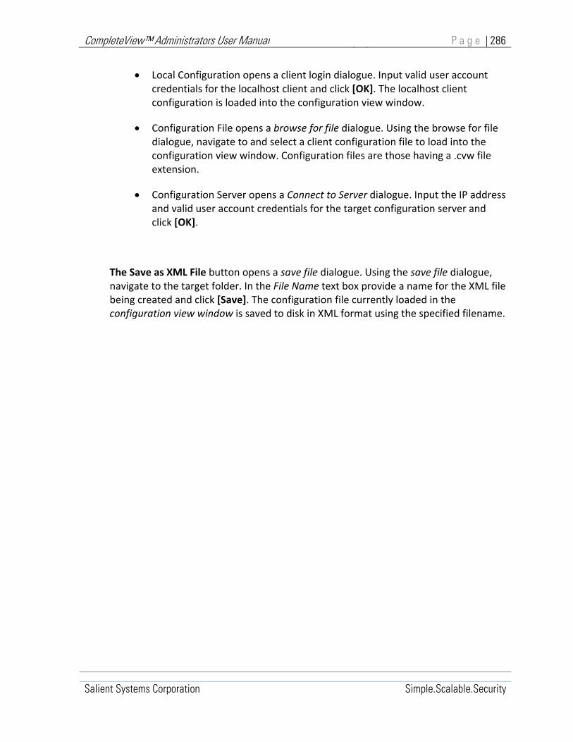
CompleteView™ Administrators User Manual P a g e | 286
Salient Systems Corporation Simple.Scalable.Security
Local Configuration opens a client login dialogue. Input valid user account credentials for the localhost client and click [OK]. The localhost client configuration is loaded into the configuration view window.
Configuration File opens a browse for file dialogue. Using the browse for file dialogue, navigate to and select a client configuration file to load into the configuration view window. Configuration files are those having a .cvw file extension.
Configuration Server opens a Connect to Server dialogue. Input the IP address and valid user account credentials for the target configuration server and click [OK].
The Save as XML File button opens a save file dialogue. Using the save file dialogue, navigate to the target folder. In the File Name text box provide a name for the XML file being created and click [Save]. The configuration file currently loaded in the configuration view window is saved to disk in XML format using the specified filename.

CompleteView™ Administrators User Manual P a g e | 287
Salient Systems, Inc. Simple.Scalable.Security
13. Configuring CompleteView™ Clients
CompleteView™ clients organize camera video from servers into Views for presentation to the user.
In order to do this configuration settings relating to various system components must be maintained by each client. Configuration settings are kept in a configuration file named clientcfg.cvw located in the CompleteView™ installation directory on each client computer.
Configuring a CompleteView™ client involves editing the content of its clientcfg.cvw configuration file using the System Configuration utility.
When a client is to be configured, the System Configuration utility performs the following actions:
1. The System Configuration utility accesses a client configuration file from one of three sources:
a. The local machine
b. An offline configuration file located on disk or in a network share
c. An offline configuration file located on a CompleteView™ Configuration Server.
When configuring the local machine client, the System Configuration utility accesses the file clientcfg.cvw located in the CompleteView™ installation directory.
When editing an offline client configuration, the System Configuration utility accesses the offline configuration file specified during the client configuration, startup dialogue.
Offline configuration filenames must include a .cvw file extension.
2. A working copy of the specified configuration file is loaded into the configuration utility and displayed at the root level of the console tree as a client configuration container.
The working copy of the target configuration file used by the utility is a ‘snapshot’ of the source configuration file. Changes made to the working copy do not take effect until the modified ‘snapshot’ has been saved and, if applicable, the local machine client has been restarted.
CompleteView™ Administrators User Manual P a g e | 288
Salient Systems, Inc. Simple.Scalable.Security
Once added to the configuration utility console tree, the client configuration (container) can be expanded to reveal its sub‐containers and sub‐containers can be expanded to reveal the component objects they contain.
Component objects may be added, deleted or reorganized within sub‐containers using System Configuration Menu commands, the configuration toolbar, or by right clicking on a selected object or container to display its context–sensitive drop‐down menu.

CompleteView™ Administrators User Manual P a g e | 289
Salient Systems, Inc. Simple.Scalable.Security
Managing Client Configurations
Client Configuration Menu
Figure 13‐1, Client Configuration Menu

CompleteView™ Administrators User Manual P a g e | 290
Salient Systems, Inc. Simple.Scalable.Security
Client Menu Items
Add Client Configuration Create a new client configuration/container.
Edit Credentials Edit selected client configuration credentials.
Delete Client Configuration Remove selected client configuration/container.
Reload Configuration Reload the selected client configuration from its source location.
Save Configuration Save the selected client configuration to its source location.
Load Configuration From Open a client configuration file from a specified location.
Save Configuration To Save the selected client configuration to a specified configuration file.
Load Backup Restore a client configuration backup file into the selected client configuration container.
Save Backup Save the selected client configuration to a backup.
User Open the User submenu relating to the selected configuration.
View Open the View submenu relating to the selected configuration.
Map Open the Map submenu relating to the selected configuration.
Server Open the Server submenu relating to the selected configuration.
Zone Open the Zone submenu relating to the selected configuration.
Figure 13‐2, Client Container Menu Items

CompleteView™ Administrators User Manual P a g e | 291
Salient Systems, Inc. Simple.Scalable.Security
To add a Client Configuration
1. At the root level of the Client Configuration console tree, select any client configuration object, then right‐click to open the Client Configuration menu. Mouse over and select Add Client Configuration.
‐ OR –
On the Client Configuration toolbar, click the [Add Client Configuration] button.
2. An Add Client Configuration dialogue will appear.
Add Client Configuration
Figure 13‐3, Add Client Configuration Dialogue
3. In the Add Client Configuration dialogue, select the radio button corresponding to the source of the configuration file to be added, where:
Local Configuration designates the client configuration file used by the local machine Video Client.
Configuration File refers to an unspecified client configuration file that has been previously saved to a disk folder or network share.
Configuration Server refers to an unspecified client configuration file stored on a CompleteView™ Configuration Server.
Click [OK]
4. One of the following responses will occur:

CompleteView™ Administrators User Manual P a g e | 292
Salient Systems, Inc. Simple.Scalable.Security
If Local Configuration was selected the local machine configuration is added to the configuration session.
If Configuration File was selected a Browse for File dialogue will appear. Using the Browse for File dialogue navigate to and select the target configuration file.
If Configuration Server was selected an Add Client Configuration logon dialogue is displayed. Input the IP Address and logon credentials for the target CompleteView™ Configuration Server and click [OK].

CompleteView™ Administrators User Manual P a g e | 293
Salient Systems, Inc. Simple.Scalable.Security
To edit Client Configuration Credentials
1. At the root level of the Client Configuration console tree, select the target client configuration object, then right‐click to open the Client Configuration menu.
2. Mouse over and select Edit Credentials…
If the current configuration has not been saved since the last edit, a Question dialogue will appear.
Question Dialogue
To proceed without saving click [Yes], to abort the operation click [No]
If the current configuration has been saved or does not need to be saved, a Login dialogue will appear.
Login Dialogue

CompleteView™ Administrators User Manual P a g e | 294
Salient Systems, Inc. Simple.Scalable.Security
3. In the Login dialogue, enter the new Username and Password that will be used to access the selected Client Configuration. Click [OK].

CompleteView™ Administrators User Manual P a g e | 295
Salient Systems, Inc. Simple.Scalable.Security
To delete a Client Configuration
1. At the root level of the Client Configuration console tree, select the target client configuration object then right‐click to open the Client Configuration menu.
2. Mouse over and select Delete Client Configuration. A Question dialogue will appear.
3. Click [Yes].
Question Dialogue
Figure 13‐4, Question Dialogue

CompleteView™ Administrators User Manual P a g e | 296
Salient Systems, Inc. Simple.Scalable.Security
To reload a Client Configuration
1. At the root level of the Client Configuration console tree, select the target client configuration object, then right‐click to open the Client Configuration menu.
2. Mouse over and select Reload Configuration.
If the current configuration has not been saved since the last edit, a Question dialogue will appear.
Question Dialogue
To proceed without saving click [Yes], to abort the operation click [No].
3. If edits to the current configuration have been saved or can be discarded, the selected client configuration container is reloaded from its source configuration file.

CompleteView™ Administrators User Manual P a g e | 297
Salient Systems, Inc. Simple.Scalable.Security
To save a Client Configuration
1. At the root level of the Client Configuration console tree, select the target client configuration object, then right‐click to open the Client Configuration menu.
2. Mouse over and select Save Configuration. An Information dialogue will appear.
Information Dialogue
Figure 13‐5, Information Dialogue
3. In the Information dialogue, click [OK].
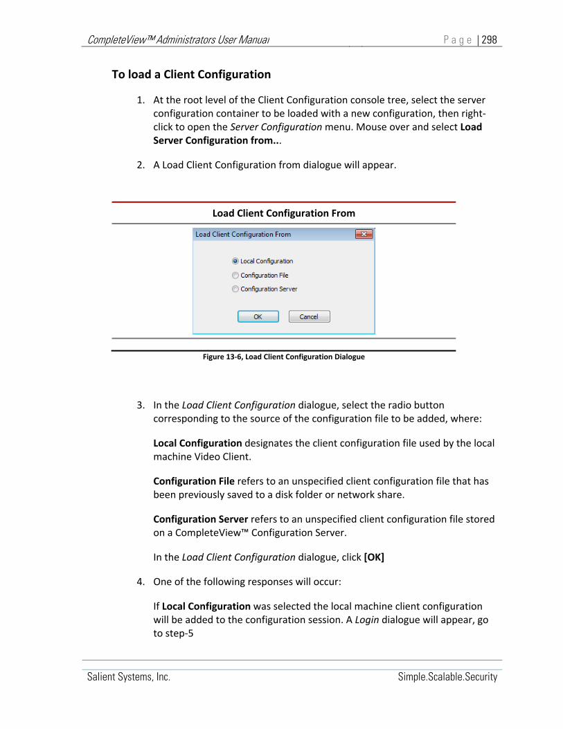
CompleteView™ Administrators User Manual P a g e | 298
Salient Systems, Inc. Simple.Scalable.Security
To load a Client Configuration
1. At the root level of the Client Configuration console tree, select the server configuration container to be loaded with a new configuration, then right‐click to open the Server Configuration menu. Mouse over and select Load Server Configuration from...
2. A Load Client Configuration from dialogue will appear.
Load Client Configuration From
Figure 13‐6, Load Client Configuration Dialogue
3. In the Load Client Configuration dialogue, select the radio button corresponding to the source of the configuration file to be added, where:
Local Configuration designates the client configuration file used by the local machine Video Client.
Configuration File refers to an unspecified client configuration file that has been previously saved to a disk folder or network share.
Configuration Server refers to an unspecified client configuration file stored on a CompleteView™ Configuration Server.
In the Load Client Configuration dialogue, click [OK]
4. One of the following responses will occur:
If Local Configuration was selected the local machine client configuration will be added to the configuration session. A Login dialogue will appear, go to step‐5

CompleteView™ Administrators User Manual P a g e | 299
Salient Systems, Inc. Simple.Scalable.Security
If Configuration File was selected a Browse for File dialogue will appear. Using the Browse for File dialogue navigate to and select the configuration file to be loaded into the selected Client Configuration object. A Login dialogue will appear, go to step‐5
If Configuration Server was selected a Load Client Configuration from dialogue is displayed.
Load Client Configuration From
In the Load Client Configuration from dialogue, input the IP Address, Username and Password for the CompleteView Configuration Server where the target, client configuration file is stored. Select the configuration file to be loaded into the selected Client Configuration object. A Login dialogue will appear, go to step‐5.
5. In the Login dialogue, input the Username and Password for the client configuration file to be loaded. Click [OK].
Load Client Configuration

CompleteView™ Administrators User Manual P a g e | 300
Salient Systems, Inc. Simple.Scalable.Security
The selected client configuration file is loaded into the selected client configuration container.

CompleteView™ Administrators User Manual P a g e | 301
Salient Systems, Inc. Simple.Scalable.Security
To save a client configuration to a file
1. At the root level of the Client Configuration console tree, select the client configuration container to be saved, then right‐click to open the Client Configuration menu. Mouse over and select Save Client Configuration to...
2. A Save Client Configuration to dialogue will appear.
Save Client Configuration To…
Figure 13‐7, Save Client Configuration
3. In the Save Client Configuration dialogue, select the radio button corresponding to the destination of the configuration file to be added, where:
Local Configuration designates that the current configuration will be saved to the local‐machine client configuration file.
Configuration File designates that the current configuration will be saved to an unspecified file in a disk folder or network share.
Configuration Server designates that the current configuration will be stored on a CompleteView™ Configuration Server.
In the Save Client Configuration to… dialogue, click [OK].
4. One of the following responses will occur:
If Local Configuration was selected the current configuration is saved to the local‐machine client configuration file, go to step‐5.
If Configuration File was selected a Save Client Configuration To dialogue will appear. Using the Save Client Configuration To dialogue navigate to and
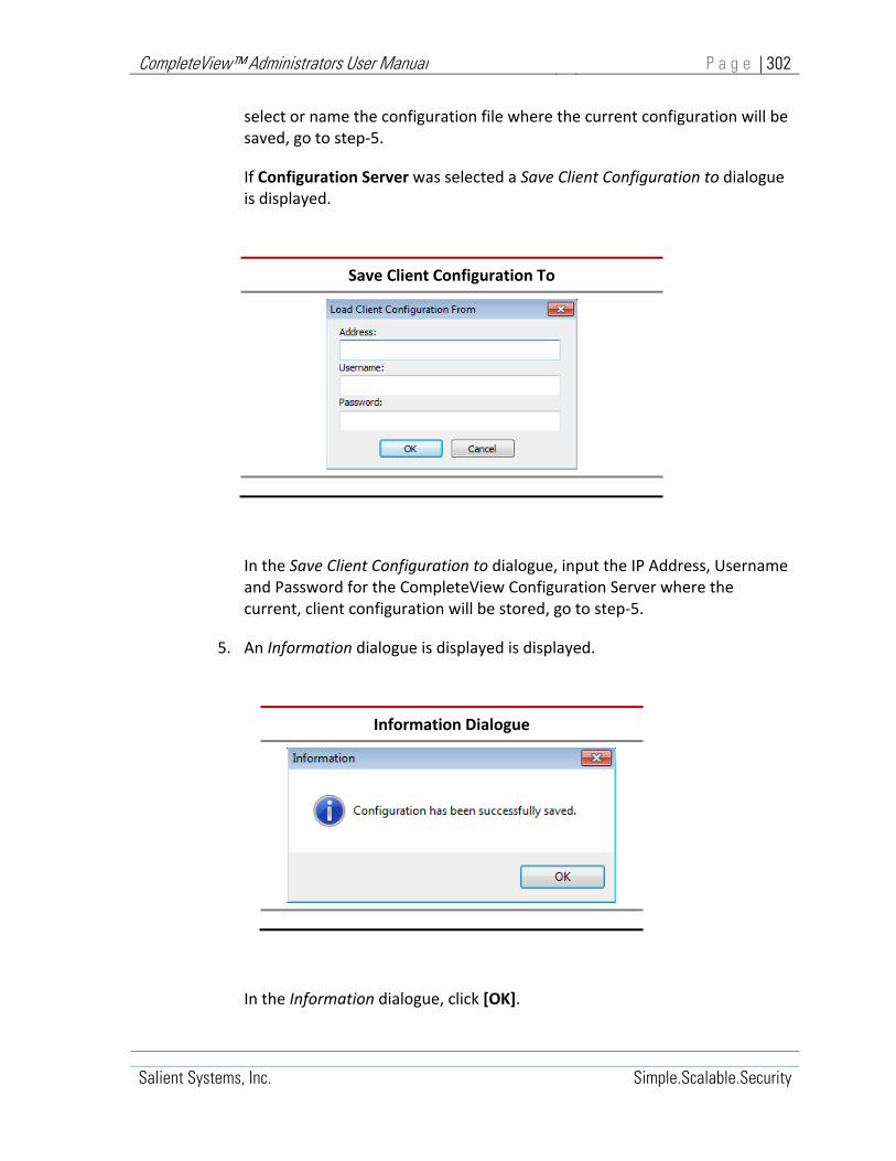
CompleteView™ Administrators User Manual P a g e | 302
Salient Systems, Inc. Simple.Scalable.Security
select or name the configuration file where the current configuration will be saved, go to step‐5.
If Configuration Server was selected a Save Client Configuration to dialogue is displayed.
Save Client Configuration To
In the Save Client Configuration to dialogue, input the IP Address, Username and Password for the CompleteView Configuration Server where the current, client configuration will be stored, go to step‐5.
5. An Information dialogue is displayed is displayed.
Information Dialogue
In the Information dialogue, click [OK].

CompleteView™ Administrators User Manual P a g e | 303
Salient Systems, Inc. Simple.Scalable.Security
To restore a client configuration backup
1. At the root level of the Client Configuration console tree, select the target client configuration object, then right‐click to open the Client Configuration menu.
2. Mouse over and select Load Backup.
Question Dialogue
If the current configuration has not been saved since the last edit, a Question dialogue will appear.
To proceed without saving click [Yes], the current configuration will be discarded when the backup configuration is restored. To abort the operation click [No].
If the current configuration has been saved since the last edit or can be discarded, an Open dialogue will appear.
3. Using the Open dialogue navigate to and select the configuration backup file to be loaded into the selected Client Configuration object.
4. Click [Open]. The selected client configuration backup file is restored to the selected client configuration container.
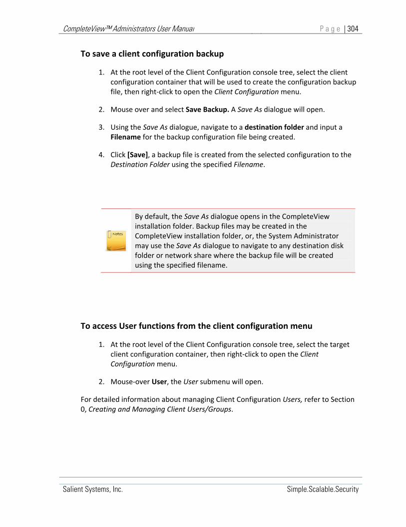
CompleteView™ Administrators User Manual P a g e | 304
Salient Systems, Inc. Simple.Scalable.Security
To save a client configuration backup
1. At the root level of the Client Configuration console tree, select the client configuration container that will be used to create the configuration backup file, then right‐click to open the Client Configuration menu.
2. Mouse over and select Save Backup. A Save As dialogue will open.
3. Using the Save As dialogue, navigate to a destination folder and input a Filename for the backup configuration file being created.
4. Click [Save], a backup file is created from the selected configuration to the Destination Folder using the specified Filename.
By default, the Save As dialogue opens in the CompleteView installation folder. Backup files may be created in the CompleteView installation folder, or, the System Administrator may use the Save As dialogue to navigate to any destination disk folder or network share where the backup file will be created using the specified filename.
To access User functions from the client configuration menu
1. At the root level of the Client Configuration console tree, select the target client configuration container, then right‐click to open the Client Configuration menu.
2. Mouse‐over User, the User submenu will open.
For detailed information about managing Client Configuration Users, refer to Section 0, Creating and Managing Client Users/Groups.

CompleteView™ Administrators User Manual P a g e | 305
Salient Systems, Inc. Simple.Scalable.Security
To access View functions from the client configuration menu
1. At the root level of the Client Configuration console tree, select the target client configuration container, then right‐click to open the Client Configuration menu.
2. Mouse‐over View, the View submenu will open.
For detailed information about managing Client Configuration Views, refer to Section 0, Creating and Managing Views.
To access Map functions from the client configuration menu
1. At the root level of the Client Configuration console tree, select the target client configuration container, then right‐click to open the Client Configuration menu.
2. Mouse‐over Map, the Map submenu will open.
For detailed information about managing Client Configuration Maps, refer to Section 0, Creating and Managing Map Objects.
To access Server functions from the client configuration menu
1. At the root level of the Client Configuration console tree, select the target client configuration container, then right‐click to open the Client Configuration menu.
2. Mouse‐over Server, the Server submenu will open.
For detailed information about managing Client Configuration Servers, refer to Section 0, Creating and Managing Server Objects.
To access Zone functions from the client configuration menu
1. At the root level of the Client Configuration console tree, select the target client configuration container. Right‐click to open the Client Configuration menu.

CompleteView™ Administrators User Manual P a g e | 306
Salient Systems, Inc. Simple.Scalable.Security
2. Mouse‐over Zone, the Zone submenu will open.
For detailed information about managing Client Configuration Zones, refer to Section 0, Creating and Client Zones/sites.
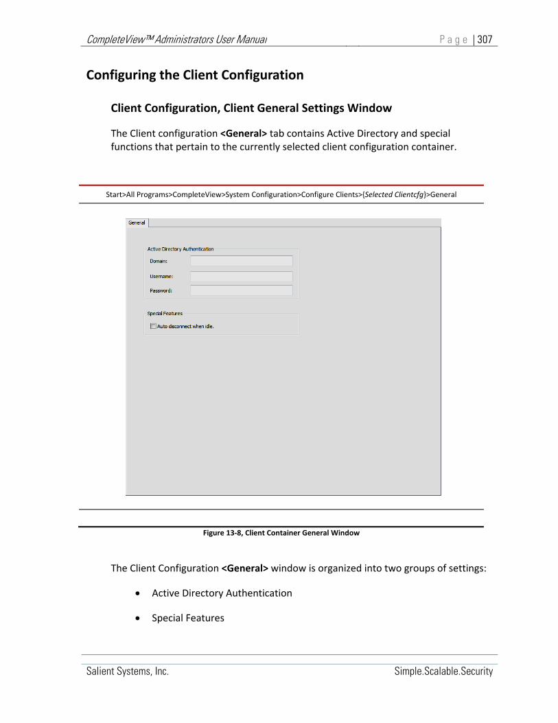
CompleteView™ Administrators User Manual P a g e | 307
Salient Systems, Inc. Simple.Scalable.Security
Configuring the Client Configuration
Client Configuration, Client General Settings Window
The Client configuration <General> tab contains Active Directory and special functions that pertain to the currently selected client configuration container.
Start>All Programs>CompleteView>System Configuration>Configure Clients>{Selected Clientcfg}>General
Figure 13‐8, Client Container General Window
The Client Configuration <General> window is organized into two groups of settings:
Active Directory Authentication
Special Features

CompleteView™ Administrators User Manual P a g e | 308
Salient Systems, Inc. Simple.Scalable.Security
Active Directory Authentication is a CompleteView™ Enterprise feature. These settings specify the AD domain and user credentials within that domain that CompleteView™ will use to authenticate network membership.
1. Domain – Specifies the domain with which CompleteView™ will authenticate.
2. Username – The domain Username used for authentication.
3. Password – The Password associated with the domain Username.
The Auto‐disconnect when idle checkbox configures the client to disconnect from servers automatically when the client window is minimized or the screen saver becomes active. Client will automatically reconnect when window is restored or screen saver is deactivated.

CompleteView™ Administrators User Manual P a g e | 309
Salient Systems, Inc. Simple.Scalable.Security
Client Configuration, Zones/Sites
CompleteView™ provides the ability to organize view layouts and maps through the Sites & Zones feature. Organizing view layouts and maps using Sites & Zones is similar to organizing files in folders. The structure created using Sites & Zones appears in the Video Client.
A Zone is the top‐level object in the structure. A Zone can contain other Zones as well as sites within it but Zones do not contain views and maps. Sites are the bottom level organizational object and can contain any number of view layouts and/or maps but no other sites and Zones.
A common structure may begin with Zones named to represent states. With the Zones, which represent a state there, may be sites representing cities. Each site there would contain view layouts and maps. For example, there may be a Zone names "Texas" with a site names "Austin" which would contain the views and maps.
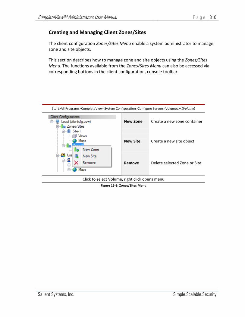
CompleteView™ Administrators User Manual P a g e | 310
Salient Systems, Inc. Simple.Scalable.Security
Creating and Managing Client Zones/Sites
The client configuration Zones/Sites Menu enable a system administrator to manage zone and site objects.
This section describes how to manage zone and site objects using the Zones/Sites Menu. The functions available from the Zones/Sites Menu can also be accessed via corresponding buttons in the client configuration, console toolbar.
Start>All Programs>CompleteView>System Configuration>Configure Servers>Volumes><{Volume}
New Zone Create a new zone container
New Site Create a new site object
Remove Delete selected Zone or Site
Click to select Volume, right click opens menu
Figure 13‐9, Zones/Sites Menu

CompleteView™ Administrators User Manual P a g e | 311
Salient Systems, Inc. Simple.Scalable.Security
To create a new zone container
1. In the Client Configuration, console tree click to expand the Zones/Sites container.
To create a new zone container subordinate within the Zones/Sites container, select the Zones/Sites container.
‐ OR ‐
To create a new zone container within a subordinate the Zone container, select the subordinate Zone container within the Zones/Sites container.
2. Right click to open the Zones/Sites menu.
3. Mouse over and select New Zone. A New Zone dialogue will appear.
4. In the New Zone dialogue box, enter a name for the zone being created.
5. Click [OK]. A new zone container is created in the Zones/Sites container or in the selected, subordinate Zone container.
Enter a Zone name
Figure 13‐10, New Zone Dialogue
To create a new site object
1. In the Client Configuration, console tree click to expand the Zones/Sites container.

CompleteView™ Administrators User Manual P a g e | 312
Salient Systems, Inc. Simple.Scalable.Security
To create a new zone container subordinate within the Zones/Sites container, select the Zones/Sites container.
‐ OR ‐
To create a new zone container within a subordinate Zone container, select the subordinate Zone container within the Zones/Sites container.
2. Right click to open the Zones/Sites menu.
3. Mouse over and select New Zone. A New Zone dialogue will appear.
4. In the New Zone dialogue box, enter a name for the zone being created.
5. Click [OK]. A new zone container is created in the Zones/Sites container or in the selected, subordinate Zone container.
Enter a Site name
Figure 13‐11, New Site Dialogue

CompleteView™ Administrators User Manual P a g e | 313
Salient Systems, Inc. Simple.Scalable.Security
To remove a site object or zone container:
1. In the Client Configuration, console tree click to expand the Zones/Sites container, then select the zone or site to be removed.
2. Right click to open the Zones/Sites menu.
3. Mouse over and select Remove. The selected zone or site is removed from the Zones/Sites container.

CompleteView™ Administrators User Manual P a g e | 314
Salient Systems, Inc. Simple.Scalable.Security
Configuring Zones/Sites
Zones, General Window
The Zones <General> window contains a textbox control that displays and enables the System Administrator to edit the name of the currently selected Zone.
Start>All Programs>CompleteView>System Configuration>Configure Clients>{Selected Clientcfg}>Zones/Sites>{Selected Zone}>General
Figure 13‐12, Zones General Window
To edit the Zone name:
1. Mouse over the textbox control and click to place the windows cursor into the textbox.
2. Type a new name or edit the existing name as required.

CompleteView™ Administrators User Manual P a g e | 315
Salient Systems, Inc. Simple.Scalable.Security
Zones Administration Window
The Zones <Administration> window contains a greyed out Users/Groups list box.
Start>All Programs>CompleteView>System Configuration>Configure Clients>{Clientcfg}>Zones/Sites>{Zone}>Administration
Figure 13‐13, Zones Administration Tab
The Zones <Administration> window performs no active functions.

CompleteView™ Administrators User Manual P a g e | 316
Salient Systems, Inc. Simple.Scalable.Security
Sites, General Window
The Sites <General> window contains a textbox control that displays and enables the System Administrator to edit the name of the currently selected Zone.
Start>All Programs>CompleteView>System Configuration>Configure Clients>{Clientcfg}>Zones/Sites>{Zone}>General
Figure 13‐14, Sites General Window
To edit the Site name:
1. Mouse over the textbox control and click to place the windows cursor into the textbox.
2. Type a new name or edit the existing name as required.

CompleteView™ Administrators User Manual P a g e | 317
Salient Systems, Inc. Simple.Scalable.Security
Sites, Administration Window
The Sites <Administration> window contains a Users/Groups list box that enables the System Administrator to select which Users and Groups are permitted to access Views and Maps within the currently selected Site.
Start>All Programs>CompleteView>System Configuration>Configure Clients>{Clientcfg}>Zones/Sites>{Zone}>General
Figure 13‐15, Sites Administration Window
`
The Users/Groups window lists the Users and groups currently defined in the CompleteView™ system. Each entry in the list is associated with a corresponding checkbox. The checkbox is used to assign users access permission to the Views and Maps contained within the currently selected Site.
In order to grant access permission to a listed User or Group, select its corresponding checkbox.

CompleteView™ Administrators User Manual P a g e | 318
Salient Systems, Inc. Simple.Scalable.Security
Client Configuration, Users/Groups
In the CompleteView™ Client, Users and Groups provide for:
Local client access permissions
The ability to organize View Layouts on a per User or per Group basis
The ability to grant users permission to access view Layouts organized on a per Site basis
The ability to assign video server account credentials to individual video client users or groups of users.
Video client user accounts are defined in the “clientcfg.cvw,” client configuration file. The client configuration can be edited using the CompleteView™ Client Configuration Utility. Client configurations include a Users/Groups container. User Objects and Group Objects exist within the client configuration Users/Groups container.
Each user object and each group object is associated with a Views container and a Maps container. Thus, unique view layouts and maps can be created for each user and each group. In this way, Views and Maps are organized on per‐user and per‐group basis.
Client Configuration Utility Console Tree
User Object Group Object
Figure 13‐16, Client Configuration Utility Console Tree
Individual users and groups may also be given permission to access Views and Maps that are organized on a per‐site basis via settings in the Zones/Sites <Administration> configuration. For more details on Zones/Sites Administration, refer to Section 0, “Sites Administration Window.”

CompleteView™ Administrators User Manual P a g e | 319
Salient Systems, Inc. Simple.Scalable.Security
Client Users/Groups Functional Overview
During normal operation, CompleteView™ users log onto a local instance of the Video Client application using account credentials associated with a user object defined in the local client configuration. The client user account provides permission to access View Layouts and Maps defined in the local client configuration.
When logged in to the Video Client, in the video client console tree, the user is presented with View Layouts and Maps as follows:
1. Those defined in the client configuration specifically for the individual User.
2. Those defined in the client configuration for any Group to which the individual User belongs.
3. Those defined in the client configuration for any Site, which specifically permits the individual User or any Group to which the individual User belongs.
View Layouts depend on camera video provided by remote video servers. Whenever a client attempts to access camera video from a server via a View Layout, the client must then also authenticate with the server being accessed.
By default, the client account credentials will be used for server authentication.
Settings in the client configuration Users/Groups, Credentials Window allow video client users and groups to be assigned account credentials for each server in the system that is known to the client configuration.
Known servers are defined in the client configuration file Servers, container. For more information about defining and configuring servers in the client configuration file, refer to Section 0, “Client Configuration, Servers.”
The same server account credentials may be specified for multiple video client users. A single server account that is shared by multiple clients enables “role” based permissions to be assigned to multiple client Users/Groups.

CompleteView™ Administrators User Manual P a g e | 320
Salient Systems, Inc. Simple.Scalable.Security
Creating and Managing Client Users/Groups
Commands available from the client configuration User Menu are used to create and manage video client users and groups.
To access the User Menu, select a user or group object and then right‐click. The User Menu will drop‐down to display.
The User Menu can also be accessed from the configuration console menu bar Server Configuration menu. Refer to Section 0, “Client Configuration Console”
Commonly used User Menu commands can also be invoked from the configuration console toolbar. Refer to Section 0, “Client Configuration Toolbar”
Start>All Programs>CompleteView>System Configuration>Configure Servers>Volumes><{Volume}
New Group Create a new Group object
New User Create a new User object
Clone
Create a new user using the configuration settings of the currently selected User
Delete Delete selected User or Group
New Password
Create a new password for the selected User
Click to select Volume, right click opens menu
Figure 13‐17, Client Users/Groups Menu

CompleteView™ Administrators User Manual P a g e | 321
Salient Systems, Inc. Simple.Scalable.Security
To create a new Group
1. In the Client Configuration console, select the Users/Groups container then right click to open the Users/Group menu.
2. Mouse over and select New Group. A New Group dialogue will appear.
3. In the New Group dialogue box, enter a name for the group container. Click [OK].
4. The new group container is created in the Users/Group container and is ready for configuration.
To create a new User
1. In the Client Configuration console, select the Users/Groups container. Right click to open the Users/Group menu.
2. Mouse over and select New User. A New User dialogue +will appear.
3. In the New User dialogue box, enter a name for the new user object. Click [OK]. A Password dialogue will appear.
4. In the Password dialogue box, enter a password for the new user object. Click [OK]. A Verify Password dialogue will appear.
5. In the Verify Password dialogue box, re‐enter the password previously entered for the new user object. Click [OK].
6. The new user object is created in the Users/Groups container and is ready for configuration.
To Clone a User
1. In the Client Configuration console, select the Users/Groups container then right click to open the Users/Group menu.
2. Mouse over and select Clone. A New User dialogue will appear.
3. In the New User dialogue box, enter a name for the new user object. Click [OK]. A Password dialogue will appear.

CompleteView™ Administrators User Manual P a g e | 322
Salient Systems, Inc. Simple.Scalable.Security
4. In the Password dialogue box, enter a password for the new user object. Click [OK]. A Verify Password dialogue will appear.
5. In the Verify Password dialogue box, re‐enter the password previously entered for the new user object. Click [OK].
6. The cloned user object is created in the Users/Groups container and is ready for configuration.
To delete a User or Group
1. In the Client Configuration console, expand the Users/Groups container.
2. Select the User or group to be deleted, then right click to open the Users/Group menu.
3. Mouse over and select Delete. A Remove User dialogue will appear.
4. In the Remove User dialogue, click [Yes] to delete the selected User or Group.
‐ OR –
Click [No] to abort the operation.
To a new password for a User
1. In the Client Configuration console, expand the Users/Groups container.
2. Select the User or group to be deleted then right click to open the Users/Group menu.
3. Mouse over and select New Password. A New Password dialogue will appear.
4. In the New Password dialogue box, enter a new password for the selected use. Click [OK]. A Verify Password dialogue will appear.
5. In the Verify Password dialogue box, re‐enter the password previously entered for the selected user object. Click [OK].

CompleteView™ Administrators User Manual P a g e | 323
Salient Systems, Inc. Simple.Scalable.Security
Configuring Client Users and Groups
Users Administration Window
The User configuration <Administration> window contains checkbox controls that enable the System Administrator to assign a variety of attributes to individual Users.
Start>All Programs>CompleteView>System Configuration>Configure Clients>{Clientcfg}>Users/Groups>{Usr/Grp}>Administration
Figure 13‐18, Users/Groups Administration Tab

CompleteView™ Administrators User Manual P a g e | 324
Salient Systems, Inc. Simple.Scalable.Security
The Administrator checkbox assigns Administrator privilege to the currently selected User. If set, the user can view and modify selected CompleteView™ Server configurations.
The Auto Fullscreen checkbox enables automatic full screen operation for the selected user. When set the CompleteView™ Client application will automatically enter Fullscreen viewing mode upon User logon.
The Auto Sequence checkbox enables Auto‐Sequence operation for the selected user. When set, the CompleteView Client application will automatically begin sequencing between live‐view layouts upon User logon.
The Disable Auto Login checkbox overrides the Auto Login feature of the Video Client. Only users whose permissions are subordinate to an Administrator are subject to Auto Login deactivation.
The Active Directory Authentication checkbox indicates that the selected User is a user object centrally managed by the Windows® Active Directory. Windows® AD user objects cannot be edited via the CompleteView™ client configuration tool.
The Hide Nodes group of checkboxes give the System Administrator control over what becomes visible to the selected User upon Video Client logon.
The Hide Nodes group includes one checkbox control for each node type that can appear in the Video Client console tree. When a Hide Nodes checkbox is selected, the corresponding node type is hidden from the video client User.
At least one node type must be unchecked, otherwise nothing will be visible to the Video Client user.
The Member of these groups list box enables the System Administrator to assign the selected User to one or more groups. The box displays a list of all local groups. Each listed group associates with a corresponding checkbox control. When checked, the user is a member of the group and inherits any view layouts that have been created for that group(s).

CompleteView™ Administrators User Manual P a g e | 325
Salient Systems, Inc. Simple.Scalable.Security
Groups Administration Window
The Group configuration <Administration> window contains checkbox controls that enable the System Administrator to assign a variety of attributes to Groups. Attributes assigned to Groups are inherited by all group‐member Users.
Start>All Programs>CompleteView>System Configuration>Configure Clients>{Clientcfg}>Users/Groups>{Usr/Grp}>Administration
The Administrator checkbox assigns Administrator privilege to the currently selected Group. If set, the group members can view and modify CompleteView™ Server configurations.
The Auto Fullscreen checkbox enables automatic full screen operation for the group members. When set the CompleteView™ Client application will automatically enter Fullscreen viewing mode upon User logon.

CompleteView™ Administrators User Manual P a g e | 326
Salient Systems, Inc. Simple.Scalable.Security
The Auto Sequence checkbox enables Auto‐Sequence operation for the selected user. When set, the CompleteView Client application will automatically begin sequencing between live‐view layouts upon User logon.
The Active Directory Authentication checkbox indicates that the selected Group is a group object centrally managed by the Windows® Active Directory. Windows® AD group objects cannot be edited via the CompleteView™ client configuration tool.
The Hide Nodes checkboxes give the System Administrator control over what becomes visible to members of the selected Group upon Video Client logon.
The Hide Nodes checkboxes include one checkbox control for each node type that can appear in the Video Client console tree. When a Hide Nodes checkbox is selected, the corresponding node type is hidden from group members when they log onto the CompleteView™ video client.
At least one node type must be unchecked, otherwise nothing will be visible to group members when they log onto the CompleteView™ video client.
The Users in this group list box enables the System Administrator to assign users to the group being configured. The box displays a list of all local users. Each listed user associates with a corresponding checkbox control. When checked, the user is a member of the group being configured and inherits any view layouts that have been created for that group.

CompleteView™ Administrators User Manual P a g e | 327
Salient Systems, Inc. Simple.Scalable.Security
Users/Groups, Credentials Window
The <Credentials> window enables the System Administrator to assign video server user credentials to local client groups and individual users.
During normal operation, CompleteView™ users log onto a local instance of the Video Client application using local user account credentials. Whenever a client attempts to access a protected system resource, such as a camera on a server, the client must then also authenticate with a valid user account on the server being accessed.
By default, the local account credentials will be used for server authentication whenever a client attempts to access a protected resource.
Settings in the <Credentials> window allow video client users and groups to be assigned account credentials for each server in the system. The same server account credentials may be specified for multiple video client users.
A single server account that is shared by multiple clients is known as a role account.
The primary benefit of using role accounts is that there is less administration required to manage users on each video server.
Start>All Programs>CompleteView>System Configuration>Configure Clients>{Clientcfg}>Users/Groups>{Usr/Grp}>Credentials
Figure 13‐19, Users/Groups Credentials Window

CompleteView™ Administrators User Manual P a g e | 328
Salient Systems, Inc. Simple.Scalable.Security
Servers List Box:
The Servers list box contains a list of each video server that is defined in the currently selected client configuration.
Credentials Settings:
These settings determine what credentials will be supplied to video servers by the local client users and groups.
Passthrough is the default credentials setting. The user credentials supplied during the client login are used to authenticate to the selected video server.
Alternate From Group – Deprecated
Alternate – Utilize the user credentials specified below to authenticate to the selected video server.
Username – The username used to authenticate to the selected video server.
Password – The valid password for the username entered above.

CompleteView™ Administrators User Manual P a g e | 329
Salient Systems, Inc. Simple.Scalable.Security
Client Configuration, Servers
In the CompleteView™ Client, servers provide video from cameras.
To the video client, servers are defined in the “clientcfg.cvw,” client configuration file. The client configuration can be edited using the CompleteView™ Client Configuration Utility. Client configurations include a Servers container. Server objects exist within the client configuration server’s container.
Each server object in the client configuration represents a remote video server in the CompleteView™ system. Server objects are configured with a valid IP address for each server. To the video client, each server represents the set of cameras that it manages. A camera list from each server is used to organize camera video into View Layouts for presentation to video client users.
Client Configuration, Servers Functional Overview
In the CompleteView™ system, Video Servers provide camera video, to Video Clients.
Settings in the Client Configuration, Users/Groups and Client Configuration, Zones/Sites are used to organize camera video from servers into View Layouts. View Layouts define the video presentation that is experienced by users when they log into the CompleteView™ video client.
In order to access the camera video provided by servers, each remote video server in the system must be defined in the client configuration Servers container.
Client Configuration, Creating and Managing Servers
Commands available from the client configuration Servers Menu are used to create and manage server objects.
To access the Servers Menu, select the Servers container in the Client Configuration Utility console tree. Right‐click to display the Servers Menu.
The Servers Menu can also be accessed from the Client Configuration menu, Server sub‐menu. Refer to Section 0, “Client Configuration Console”
Commonly used User Menu commands can also be invoked from the configuration console toolbar. Refer to Section 0, “Client Configuration Toolbar”
Server objects are created and managed by using functions available in the Server Container Menu and the Server Object Menu.

CompleteView™ Administrators User Manual P a g e | 330
Salient Systems, Inc. Simple.Scalable.Security
Menu functions can also be accessed via buttons on the client configuration Console Toolbar.
Start>All Programs>CompleteView>System Configuration>Configure Clients>Servers><{Server}
Click to select Server, right click opens menu
Figure 13‐20, Servers Menu
Servers Menu Items
Add Server Create a new server object in the client configuration, Servers container.
Change Server Address Change the IP address of the selected server.
Delete Server Delete a server object from the client configuration, Servers container.
Update Cached Information
Update cached information from the selected server.
Table 13‐1, Servers Menu Items
To add a server to the client configuration
1. In the Client Configuration console tree, select the Server container. Right click to open the Server Menu.

CompleteView™ Administrators User Manual P a g e | 331
Salient Systems, Inc. Simple.Scalable.Security
2. Mouse over and select Add Server. An Add Server dialogue will appear.
Add Server Dialogue
Enter IP address of remote server being added
Figure 13‐21, Add Server Dialogue
3. In the Add Server dialogue box, enter the IP address of the server being added. A Question dialogue box will appear:
Add Server Question Dialogue
Click [Yes] or [No]
Figure 13‐22, Add Server Question Dialogue
As new servers are added to the client configuration, the client configuration utility automatically queries each server for camera configuration information. The Question dialogue refers to the account credentials that will be used by the configuration utility during setup. Credentials established here do not affect the credentials used by video client users that access the server during normal operation.
Click [No] and the configuration utility will access the server using the CompleteView™ default admin account username and password.
‐ OR –
Click [Yes] and a Login dialogue will appear
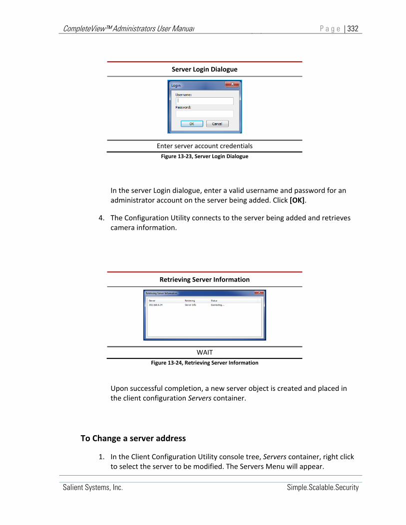
CompleteView™ Administrators User Manual P a g e | 332
Salient Systems, Inc. Simple.Scalable.Security
Server Login Dialogue
Enter server account credentials
Figure 13‐23, Server Login Dialogue
In the server Login dialogue, enter a valid username and password for an administrator account on the server being added. Click [OK].
4. The Configuration Utility connects to the server being added and retrieves camera information.
Retrieving Server Information
WAIT
Figure 13‐24, Retrieving Server Information
Upon successful completion, a new server object is created and placed in the client configuration Servers container.
To Change a server address
1. In the Client Configuration Utility console tree, Servers container, right click to select the server to be modified. The Servers Menu will appear.

CompleteView™ Administrators User Manual P a g e | 333
Salient Systems, Inc. Simple.Scalable.Security
2. In the Servers Menu, mouse over and select Change Server Address. A Change Server Address dialogue will appear.
Change Server Address Dialogue
Enter server address, click [OK]
Figure 13‐25, Change Server Address Dialogue
3. In the Change Server Address dialogue, enter a new address for the server being modified. Click [OK].
The Configuration Utility will attempt to access the server at its new address. When successful configuration information for the modified server will be retrieved and cached, server information is updated.

CompleteView™ Administrators User Manual P a g e | 334
Salient Systems, Inc. Simple.Scalable.Security
To delete a server from the client configuration
1. In the Client Configuration Utility console tree, Servers container, right click to select the server object to be deleted. The Servers Menu will appear.
2. In the Servers Menu, mouse over and select Delete Server. The selected server object is deleted from the Servers container.
When Deleting a Server, the selected server object is deleted from the Servers container without further confirmation or warning.

CompleteView™ Administrators User Manual P a g e | 335
Salient Systems, Inc. Simple.Scalable.Security
To update cached server information
1. In the Client Configuration Utility console tree, Servers container, right click to select the server object to be updated. The Servers Menu will appear.
2. In the Servers Menu, mouse over and select Update Cached Information.
A Retrieving Server Information dialogue will briefly display.
Retrieving Server Information
WAIT
When successful, configuration information is retrieved from the target server and used to update information cached in the current client configuration.

CompleteView™ Administrators User Manual P a g e | 336
Salient Systems, Inc. Simple.Scalable.Security
Client Configuration, Configuring Servers
In the client configuration, server objects only require that a valid IP address be provided for each remote server being represented by each server object.
Server IP addresses are provided for server objects at the time the server object is created. Server objects require no further configuration.
Each server object in the client configuration is associated with a list of cameras retrieved from the remote server it represents. The cameras list for the selected server is visible the <Cameras> window in the Client Configuration console Details Pane.

CompleteView™ Administrators User Manual P a g e | 337
Salient Systems, Inc. Simple.Scalable.Security
Servers, Cameras Window
The Servers <Cameras> window contains a list box that contains a list of the cameras that are managed by the currently selected server.
To access the <Cameras> window for a particular server object: in the client configuration Servers container, select the target server object.
The <Cameras> window for the selected server object will appear in the configuration utility details pane.
Start>All Programs>CompleteView>System Configuration>Configure Clients>{Clientcfg}>Servers>{Server}>Cameras
Figure 13‐26, Servers Cameras Window
Cameras Window Controls
Cameras List of cameras managed by the selected server.
Update Cached Information Update cached information from the selected server.
Table 13‐2, Cameras Window Controls

CompleteView™ Administrators User Manual P a g e | 338
Salient Systems, Inc. Simple.Scalable.Security
Client Configuration, View Layouts
View Layouts define the format of video presentations available to users when they log into the CompleteView™ video client application.
View Layouts are defined in the client configuration file “clientcfg.cvw.” The client configuration can be edited using the CompleteView™ Client Configuration Utility.
Client configurations include multiple Views containers. View Layout objects exist within the Views containers.
Views containers are subordinate to User and Group objects. In the CompleteView™ Enterprise edition, Views containers are also subordinate to Sites. Every User object, Group object and Site object has an associated Views container that may contain an unlimited number of View Layouts. Thus, custom View Layouts may be established for individual users, roles performed by groups of users and by physical location.
Views Layouts Functional Overview
During operation, CompleteView™ users log onto a local instance of the Video Client application using account credentials associated with a user object defined in the local client configuration. The client user account provides permission to access View Layouts defined in the client configuration.
When logged in to the Video Client, in the video client console tree, the user is presented with View Layouts as follows:
1. Those defined in the client configuration specifically for the individual User.
2. Those defined in the client configuration for any Group to which the individual User belongs.
3. Those defined in the client configuration for any Site, which specifically permits the individual User or any Group to which the individual User belongs.
View Layouts depend on camera video provided by remote video servers. Whenever a client attempts to access camera video from a server via a View Layout, the client must then also authenticate with the server being accessed.
By default, the client account credentials will be used for server authentication.

CompleteView™ Administrators User Manual P a g e | 339
Salient Systems, Inc. Simple.Scalable.Security
Settings in the client configuration Users/Groups, Credentials Window allow video client users and groups to be assigned account credentials for each server in the system that is known to the client configuration.
Known servers are defined in the client configuration file Servers, container. For more information about defining and configuring servers in the client configuration file, refer to Section 0, “Client Configuration, Servers.”
The same server account credentials may be specified for multiple video client users. A single server account that is shared by multiple clients enables “role” based permissions to be assigned to multiple client Users/Groups.
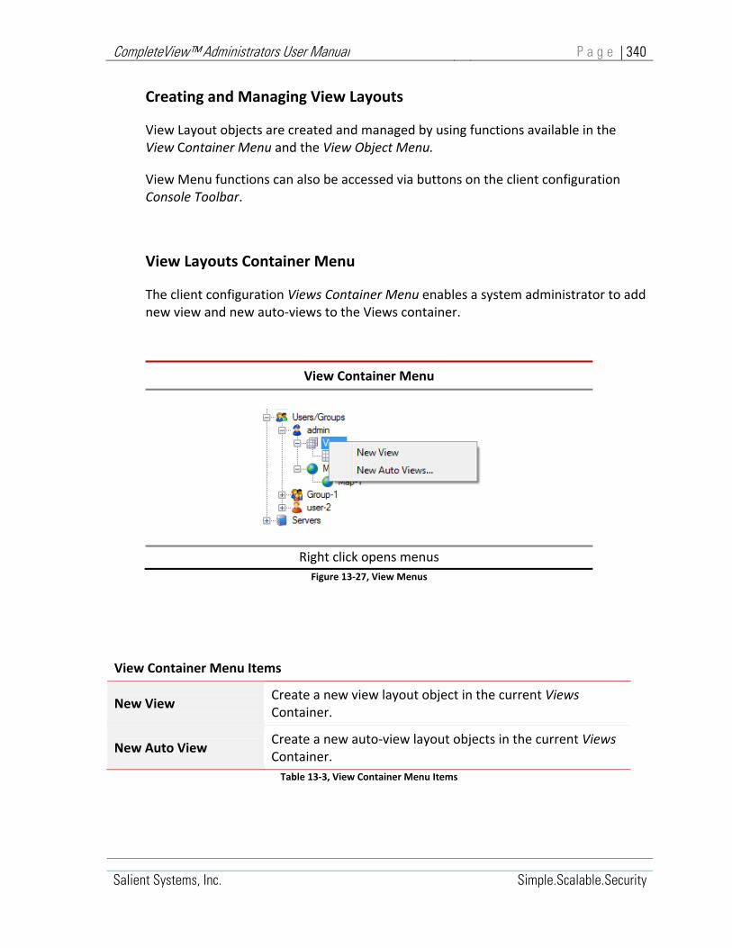
CompleteView™ Administrators User Manual P a g e | 340
Salient Systems, Inc. Simple.Scalable.Security
Creating and Managing View Layouts
View Layout objects are created and managed by using functions available in the View Container Menu and the View Object Menu.
View Menu functions can also be accessed via buttons on the client configuration Console Toolbar.
View Layouts Container Menu
The client configuration Views Container Menu enables a system administrator to add new view and new auto‐views to the Views container.
View Container Menu
Right click opens menus
Figure 13‐27, View Menus
View Container Menu Items
New View Create a new view layout object in the current Views Container.
New Auto View Create a new auto‐view layout objects in the current Views Container.
Table 13‐3, View Container Menu Items

CompleteView™ Administrators User Manual P a g e | 341
Salient Systems, Inc. Simple.Scalable.Security
To create a new View layout object
1. In the Client Configuration console tree, select the Views container. Right‐click to open the Views menu.
2. Mouse over and select New View. A New View dialogue will appear.
New View Dialogue
Enter View name and click [OK]
Figure 13‐28, New View Dialogue
3. In the New View dialogue box, enter a name for the view being created.
4. Click [OK]. A new view object is created in the current Views container.

CompleteView™ Administrators User Manual P a g e | 342
Salient Systems, Inc. Simple.Scalable.Security
To create a new Auto View
The Auto View function automatically creates a View object in the current Views container and populates it with all of the cameras from a specified server.
1. In the Client Configuration console tree, select the Views Container then right‐click to open the Views Container Menu.
2. Mouse over and select New Auto Views. An Autopopulate Views dialogue appears.
Autopopulate Views
Figure 13‐29, Autopopulate Views Dialogue
3. In the Autopopulate Views dialogue:
a. Open the Server drop‐down menu, mouse over and select the server from which to auto‐populate.
b. Open the Aspect Ratio drop‐down menu. Mouse over and select the desired aspect ratio.
c. Open the Grid Size drop‐down menu, then mouse over and select the desired grid size.
4. Click [OK]. The new View object is created in the Views container and populated with cameras from the specified server.
The new View object configuration may now be edited per the procedures described in Section 0, “Configuring Views.”

CompleteView™ Administrators User Manual P a g e | 343
Salient Systems, Inc. Simple.Scalable.Security
View Layout Menu
The client configuration View Menu enables a system administrator to add and remove view objects within a views container.
Figure 13‐30, View Object Menu
View Object Menu Items
New View Create a new View Layout object
Auto Populate Automatically create and configures a new View Layout object
Clone Create a copy of the currently selected view layout object
Remove View Removes the currently selected view layout object
Save As Template Saves the currently selected view configuration as a template
Apply Template Applies a saved template to the currently selected view layout
Delete Template Removes the selected Template
Table 13‐4, View Object Menu Items
View Object Menu
Click to select View, Right click opens menu

CompleteView™ Administrators User Manual P a g e | 344
Salient Systems, Inc. Simple.Scalable.Security
To create a new View
1. In the Client Configuration console tree, select the Views container, then right‐click to open the Views menu.
2. Mouse over and select New View. A New View dialogue will appear.
New View Dialogue
Enter View name and click [OK]
Figure 13‐31, New View Dialogue
3. In the New View dialogue box, enter a name for the view being created. Click [OK]. A new view object is created in the current Views container.

CompleteView™ Administrators User Manual P a g e | 345
Salient Systems, Inc. Simple.Scalable.Security
To auto‐populate a View
1. In the Client Configuration, console tree expand the Views container and then select the View Object that will be auto‐populated.
2. Right‐click the selected View Object; the view object menu will appear.
3. Mouse over and select Autopopulate… An Autopopulate Views dialogue displays.
Autopopulate Views
Figure 13‐32, Autopopulate Views
4. In the Autopopulate Views dialogue:
a. Open the Server drop‐down menu, mouse over and select the server from which to auto‐populate.
b. Open the Aspect Ratio drop‐down menu, then mouse over and select the desired aspect ratio.
c. Open the Grid Size drop‐down menu, then mouse over and select the desired grid size.
5. Click [OK]. The new View object is created in the Views container and populated with cameras from the specified server.
The new View object configuration may now be edited per the procedures described in Section 0, “Configuring Views.”

CompleteView™ Administrators User Manual P a g e | 346
Salient Systems, Inc. Simple.Scalable.Security
To clone a View
1. In the Client Configuration console tree, expand the Views container. Select the View Object that will be cloned.
2. Mouse over and select Clone… A New View dialogue will appear.
New View Dialogue
Enter View name and click [OK]
3. In the New View dialogue box, enter a name for the view being created. Click [OK]. A new view object is created in the current Views container.
To remove a View Layout
1. In the Client Configuration, console tree expand the Views container and then select the View Object that will be auto‐populated.
2. Right‐click the selected View Object; the view object menu will appear.
3. Mouse over and select Remove View. The selected view object is deleted from the Views Container.
When removing a View Layout, the selected View Layout object is deleted from the Views container without further confirmation or warning.

CompleteView™ Administrators User Manual P a g e | 347
Salient Systems, Inc. Simple.Scalable.Security
To save a View Layout as a template
Once created, View Layout objects may be saved as a template that can be applied to other view layout objects.
1. In the Client Configuration console tree, expand the Views container and select the View Object that will be used as a template.
2. Right‐click the selected View Object; the view object menu will appear.
3. Mouse over and select Save as Template. A New Template dialogue will appear.
New Template Dialogue
Enter Template name and click [OK]
4. In the New Template dialogue box, enter a name for the template being created. Click [OK].
A new view template is saved using the specified template name; the new view template does not appear in the Views container.

CompleteView™ Administrators User Manual P a g e | 348
Salient Systems, Inc. Simple.Scalable.Security
The list of view templates is accessible from the View object menu, Apply Template function.

CompleteView™ Administrators User Manual P a g e | 349
Salient Systems, Inc. Simple.Scalable.Security
To apply a template to a View Layout
1. In the Client Configuration, console tree expand the Views container and select the View Object that will be applied a template.
2. Right‐click the selected View Object; the view object menu will appear.
3. Mouse over Apply Template. A menu list of available templates will appear.
4. In the list of available templates, mouse‐over and select the template that will be applied to the selected view object; a warning will be displayed:
Apply Template Warning
Figure 13‐33, Apply Template Warning
5. To apply the selected Template, Click [Yes]. The selected template is applied to the selected view object.

CompleteView™ Administrators User Manual P a g e | 350
Salient Systems, Inc. Simple.Scalable.Security
To delete a View template
1. In the Client Configuration console tree, expand the Views container and select a View Object.
2. Right‐click the selected View Object; the view object menu will appear.
3. Mouse‐over Delete Template, a menu list of available templates will appear.
6. In the list of available templates, mouse‐over and select the template to be deleted; a warning will appear:
Delete Template Warning
Figure 13‐34, Delete Template Warning
7. To delete the selected Template, Click [Yes].

CompleteView™ Administrators User Manual P a g e | 351
Salient Systems, Inc. Simple.Scalable.Security
Configuring View Layouts
View Layouts, General Settings Window
The View Layout object <General> window contains settings that determine how the selected View Layout is presented to the user.
Individual View Layouts may be presented as one in a sequence of rotating View Layouts, the <General> settings are used to enable and configure rotating behavior for the selected View Layout.
Start>All Programs>CompleteView>System Configuration>Configure Clients>{Client}>Users/Groups>{User}>Views>{View}
Figure 13‐35, View Object General Settings Window
View Layout General Settings
View Name The name of the view layout as it is displayed to the user
In Sequence Enables view layout timed rotation behavior
Dwell Time Specifies timed rotation sequence pause in seconds
Table 13‐5, View Layout General Settings

CompleteView™ Administrators User Manual P a g e | 352
Salient Systems, Inc. Simple.Scalable.Security
View Layout, Edit Window
Start>All Programs>CompleteView>System Configuration>Configure Clients>{Client}>Users/Groups>{User}>Views>{View}
Figure 13‐36, View Layout Object Edit Window

CompleteView™ Administrators User Manual P a g e | 353
Salient Systems, Inc. Simple.Scalable.Security
View Layout Edit Controls
Server Servers, contains a drop‐down list of each video server object that is defined in the currently selected client configuration, Servers container.
Cameras Cameras, contains a scroll‐box list of all cameras that are available on the video server currently selected in the Server list. Each camera is represented by a thumbnail still image
Refresh Refresh, Reloads the list of cameras and thumbnail images for the currently selected video server.
Aspect Ratio Aspect Ratio sets the aspect ratio of the tiled view display. Set the aspect ratio control to match the aspect ratio of the target display monitor.
Grid Scale Grid Scale enables a snap‐to grid in the layout editor window and determines the grid size.
Title Bar Check to overlay the title bar on the video window. Note this does not change the aspect ratio of the video window
Frame Rate Sets the maximum live view frame rate for all currently selected camera
Quality Sets the video compression visual quality (low, medium, high) for all currently selected cameras
Table 13‐6, View Layout Edit Controls

CompleteView™ Administrators User Manual P a g e | 354
Salient Systems, Inc. Simple.Scalable.Security
To add a camera to a view layout
Add cameras to the view layout by dragging a camera thumbnail image from the camera list onto the grid position where it should appear.
1. In the View Layout <Edit> window cameras list, mouse over and click to drag a camera thumbnail onto the onto the view layout drawing pane. A Viewing Tile containing video from the selected camera will appear on the grid.
Start>All Programs>CompleteView>System Configuration>Configure Clients>{Client}>Users/Groups>{User}>Views>{View}
Figure 13‐37, View Layout Add Camera
When adding QuickTrack cameras to a View Layout, a maximum of one QuickTrack camera can be added per view layout.

CompleteView™ Administrators User Manual P a g e | 355
Salient Systems, Inc. Simple.Scalable.Security
To resize a camera in a view layout
The lower right‐hand corner of each camera Viewing Tile is an Anchor Point. Click and drag the anchor point to resize the camera video Viewing Tile. Release the mouse button when the Viewing Tile reaches the desired size.
Start>All Programs>CompleteView>System Configuration>Configure Clients>{Client}>Users/Groups>{User}>Views>{View}
Cameras can be resized to a 16x9 aspect ratio, or, to a 4x3 aspect ratio from their original size. Corridor View cameras at a 9x16 aspect ratio, can be resized to a 4x3 aspect ratio from their original size.

CompleteView™ Administrators User Manual P a g e | 356
Salient Systems, Inc. Simple.Scalable.Security
To Delete a camera from a View Layout
In the drawing pane of the View Layout <Edit> window:
1. Mouse over and then left‐click on a camera video Viewing Tile to select it, the selected camera video viewing tile will become highlighted.
2. Press the delete button on the keyboard, the selected camera video viewing tile will be deleted from the layout pane of the View Layout <Edit> window.
‐ OR‐
1. Mouse over and then right‐click on a camera video Viewing Tile to select it, the selected camera video viewing tile will become highlighted and a [Delete] button will appear.
2. Mouse over and select the [Delete] button. The selected camera video viewing tile will be deleted from the layout pane of the View Layout <Edit> window.
Start>All Programs>CompleteView>System Configuration>Configure Clients>{Client}>Users/Groups>{User}>Views>{View}

CompleteView™ Administrators User Manual P a g e | 357
Salient Systems, Inc. Simple.Scalable.Security
Adding Maps and Web Pages to a View Layout
In the View Layout <Edit> window, the Cameras list will contain three non‐camera objects:
Map Viewing Tile
Web Page Viewing Tile
Empty Viewing Tile
Start>All Programs>CompleteView>System Configuration>Configure Clients>{Client}>Users/Groups>{User}>Views>{View}
Dropping a Map Viewing Tile onto the View Layout drawing surface adds a map to the view layout.
Dropping a Web Page Viewing Tile onto the View Layout drawing surface adds a web page to the view layout.
Dropping an Empty Viewing Tile onto the View Layout drawing surface adds an empty tile o the view layout.

CompleteView™ Administrators User Manual P a g e | 358
Salient Systems, Inc. Simple.Scalable.Security
To add a map to the View Layout
Maps are added to a View Layout in a manner similar to the way camera video is added.
1. From the cameras list in the View Layout <Edit> window, mouse over and click to drag the Map thumbnail onto the View Layout drawing pane. A Map dialogue will appear.
Figure 13‐38, Add Map Dialogue
2. In the Map dialogue, select a map and then click [OK].
‐ OR –
Double‐click to select a map.
A Viewing Tile for the selected map will appear on the drawing pane. The map‐viewing tile may be moved and resized.
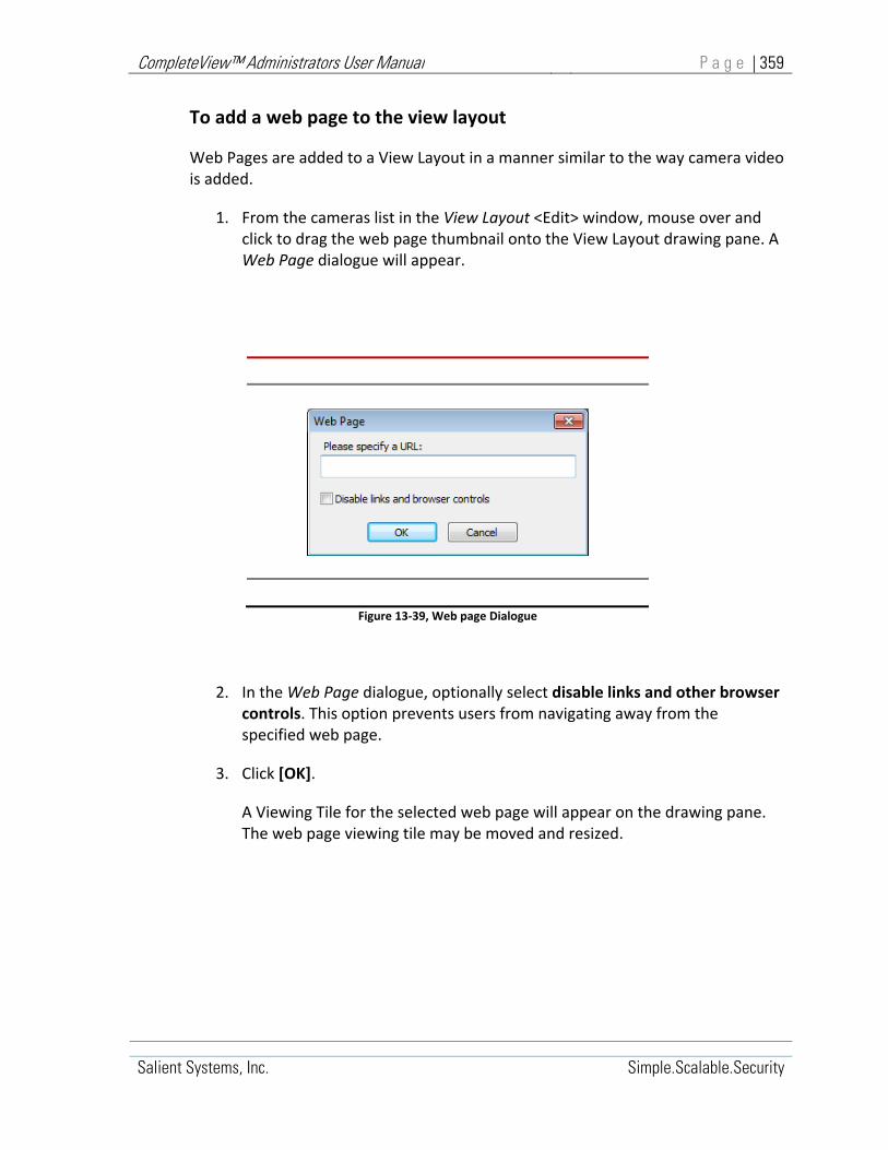
CompleteView™ Administrators User Manual P a g e | 359
Salient Systems, Inc. Simple.Scalable.Security
To add a web page to the view layout
Web Pages are added to a View Layout in a manner similar to the way camera video is added.
1. From the cameras list in the View Layout <Edit> window, mouse over and click to drag the web page thumbnail onto the View Layout drawing pane. A Web Page dialogue will appear.
Figure 13‐39, Web page Dialogue
2. In the Web Page dialogue, optionally select disable links and other browser controls. This option prevents users from navigating away from the specified web page.
3. Click [OK].
A Viewing Tile for the selected web page will appear on the drawing pane. The web page viewing tile may be moved and resized.

CompleteView™ Administrators User Manual P a g e | 360
Salient Systems, Inc. Simple.Scalable.Security
Client Configuration, Maps
Creating and Managing Map Objects
Map objects are created and managed by using functions available in the Map Menu.
Map Menu functions can also be accessed via buttons on the client configuration Console Toolbar.
The client configuration Map Menu enables a system administrator to add and remove map objects within the maps container.
Start>All Programs>CompleteView>System Configuration>Configure Clients>Maps
New Map Create a new Map object
Remove Delete selected Map object
Click to select Map, right click opens menu
Figure 13‐40, Map Menu
To create a new map object
1. In the Client Configuration console tree, expand the Zones/Sites container and select the Maps container.
2. Right click to open the Maps menu.
3. Mouse over and select New Map. A New Map dialogue will appear.
4. In the New Map dialogue box, enter a name for the map to be created. Click [OK]. A new Map object is created in the Maps container.

CompleteView™ Administrators User Manual P a g e | 361
Salient Systems, Inc. Simple.Scalable.Security
To delete a map object
1. In the Client Configuration, console tree expand the Zones/Sites container.
2. Within the expanded Zones/Sites container, expand Maps container and then select the Map object to be deleted.
3. Right click to open the Maps menu.
4. Mouse over and select Remove. The selected Map is deleted from the Maps container.

CompleteView™ Administrators User Manual P a g e | 362
Salient Systems, Inc. Simple.Scalable.Security
Configuring Maps
Maps, General Window
The <General> tab enables the System Administrator to import image files for use as maps and to select the imported map image for use in the View Layout currently being configured.
Start>All Programs>CompleteView>System Configuration>Configure Clients>{Client}>Users/Groups>{User}>Views>{View}

CompleteView™ Administrators User Manual P a g e | 363
Salient Systems, Inc. Simple.Scalable.Security
Map <General> Settings Window Controls
Map Name Map Name is the name given to the map currently being configured.
Image Name Image Name is the name of the image being used in the map currently being configured.
Images Images is the list of images available for use in the map currently being configured.
Import Button The Import Button is used to import an image file into the Images list.
Select Button The Select Button is used to select an image from the Images list for use in the map currently being configured.
Delete Button The Delete Button is used to delete an image from the Images.
Cached File Name Cached File Name displays the temporary filename assigned to the imported image currently selected in the Images list.
Table 13‐7, Map General Settings Controls
To import an image file
1. In the Client Configuration, Map <General> window, click [Import]. An Open file dialogue will appear.
Open File Dialogue
Double‐click file selection
Figure 13‐41, Maps Open File Dialogue
2. Using the Open file dialogue, navigate to and double‐click the image file to be imported.

CompleteView™ Administrators User Manual P a g e | 364
Salient Systems, Inc. Simple.Scalable.Security
3. The selected image is added to the list of available map images in the Images list box
To select an imported image file
1. In the Client Configuration, Map <General> window, Images list box, mouse over and click to highlight a listed image.
A preview of the image will appear
The image Cached File Name will be displayed
2. When the desired image is highlighted, click [Select].
The name of the newly selected image will appear in the Image Name field.
To delete an imported image file
1. In the Client Configuration, Map <General> window, Images list box, mouse over and click to highlight the image to be deleted.
A preview of the image will appear
The image Cached File Name will be displayed
2. When the desired image is highlighted, click [Delete].
The image file is deleted from the Images list box.

CompleteView™ Administrators User Manual P a g e | 365
Salient Systems, Inc. Simple.Scalable.Security
Import any number of files as maps. Once imported, an image becomes available for use as a map. Once selected, an image is used as a map.

CompleteView™ Administrators User Manual P a g e | 366
Salient Systems, Inc. Simple.Scalable.Security
Map, Edit Window
Once a map image has been selected by using settings in the <General> window, the map can be tailored using the <Edit> window, to closely represent the placement and orientation of cameras in an actual physical location.
Using the <Edit> window, the System Administrator may:
Place cameras on the map
Edit camera field‐of‐view‐cones
Link to other maps
Figure 13‐42, Map Edit Window
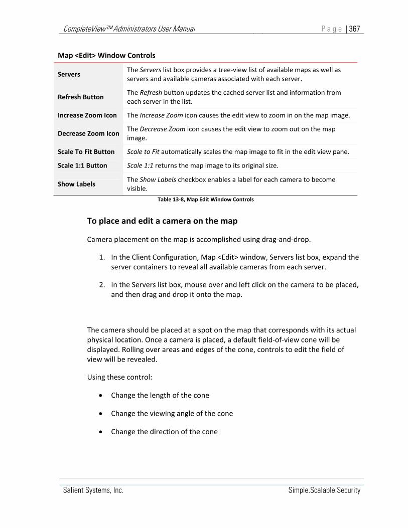
CompleteView™ Administrators User Manual P a g e | 367
Salient Systems, Inc. Simple.Scalable.Security
Map <Edit> Window Controls
Servers The Servers list box provides a tree‐view list of available maps as well as servers and available cameras associated with each server.
Refresh Button The Refresh button updates the cached server list and information from each server in the list.
Increase Zoom Icon The Increase Zoom icon causes the edit view to zoom in on the map image.
Decrease Zoom Icon The Decrease Zoom icon causes the edit view to zoom out on the map image.
Scale To Fit Button Scale to Fit automatically scales the map image to fit in the edit view pane.
Scale 1:1 Button Scale 1:1 returns the map image to its original size.
Show Labels The Show Labels checkbox enables a label for each camera to become visible.
Table 13‐8, Map Edit Window Controls
To place and edit a camera on the map
Camera placement on the map is accomplished using drag‐and‐drop.
1. In the Client Configuration, Map <Edit> window, Servers list box, expand the server containers to reveal all available cameras from each server.
2. In the Servers list box, mouse over and left click on the camera to be placed, and then drag and drop it onto the map.
The camera should be placed at a spot on the map that corresponds with its actual physical location. Once a camera is placed, a default field‐of‐view cone will be displayed. Rolling over areas and edges of the cone, controls to edit the field of view will be revealed.
Using these control:
Change the length of the cone
Change the viewing angle of the cone
Change the direction of the cone

CompleteView™ Administrators User Manual P a g e | 368
Salient Systems, Inc. Simple.Scalable.Security
It is not possible to add a QuickTrack camera to a map.
To display a snapshot from a camera on the map
On the map being edited, mouse over a camera; a snapshot from the camera video stream will be displayed.

CompleteView™ Administrators User Manual P a g e | 369
Salient Systems, Inc. Simple.Scalable.Security
To display a live‐view stream from a camera on the map
On the map being edited, mouse over a camera and then right‐click. A camera pop‐up menu will display.
From the pop‐up menu, mouse over and select Live View.
A Live View window will appear.
Figure 13‐43, Map Camera Live View
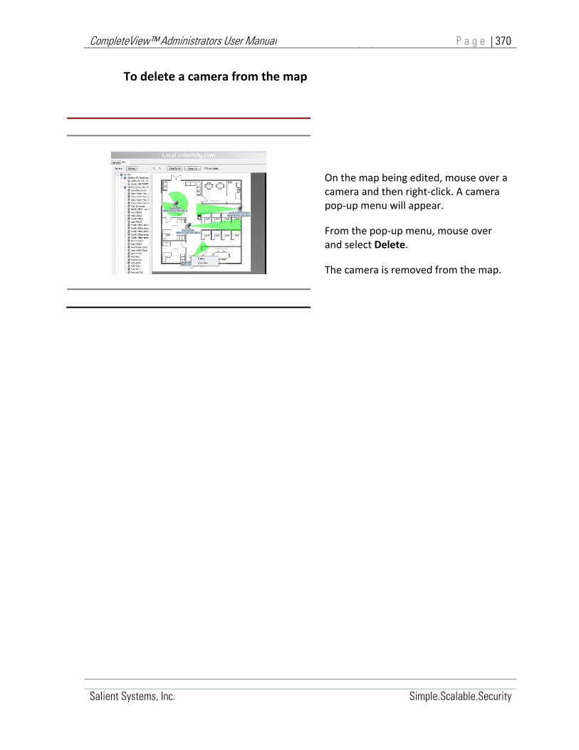
CompleteView™ Administrators User Manual P a g e | 370
Salient Systems, Inc. Simple.Scalable.Security
To delete a camera from the map
On the map being edited, mouse over a camera and then right‐click. A camera pop‐up menu will appear.
From the pop‐up menu, mouse over and select Delete.
The camera is removed from the map.

CompleteView™ Administrators User Manual P a g e | 371
Salient Systems, Inc. Simple.Scalable.Security
To place a link to another map
Map link placement onto the map being edited is accomplished using drag‐and‐drop.
1. In the Client Configuration, Map <Edit> window, Servers list box, expand the Map containers to reveal all available maps.
2. In the Servers list box, mouse over and left click on the map link to be placed and then drag and drop it onto the map being edited.
To test a link to another map
On the map being edited, mouse over a map link and then right‐click. A map link pop‐up menu will appear.
From the pop‐up menu, mouse over and select Jump To Map Link.
To delete a map link
1. On the map being edited, mouse over a map link and then right‐click. A map link pop‐up menu will appear.
2. From the pop‐up menu, mouse over and select Delete Map Link.
3. The map link is removed from the map being edited.

CompleteView™ Administrators User Manual P a g e | 372
Salient Systems, Inc. Simple.Scalable.Security
14. CompleteView™ Server Process Maintenance
CompleteView Server Processes run under the Microsoft® Windows® operating system as Windows® System Services. Each server process listens for and responds to client request via an assigned TCP port. Server‐process maintenance tasks are performed from the Windows® Command Interpreter by invoking a server process executable image and passing to it, command line arguments.
Ordinarily, system administrators are not required to perform Server Process maintenance. Server processes install automatically during software installation and start automatically during system boot. Server Process maintenance tasks are normally performed only during troubleshooting by Salient Systems customer support or engineering staff.
Server processes install automatically during CompleteView™ Software installation when the corresponding Server Application checkbox is selected in the “Select Packages” dialog.
If “CompleteView Server” was selected with a checkmark during installation, the “CompleteView Server” process and the “CompleteView Administrative Service” process was automatically installed.
If “CompleteView Config Server” was selected with a checkmark during installation, the “CompleteView Configuration Server” process was automatically installed.
If “Server Applications” was selected with a checkmark during installation, all processes related to the “CompleteView Server” and “CompleteView Configuration Server” were automatically installed.
The default location of the CompleteView installation directory can be found at the “.\Program Files\completeview\” subdirectory of the Windows system root directory.
Server‐process maintenance tasks are performed from the Windows® command shell. To open a command shell, click start and click run. A Run dialogue box will appear. Type {cmd} in the Run dialogue text box and then click [OK], a Windows® command shell will open.
Navigate to the CompleteView installation directory.
Server Applications
Figure 14-1, Server Package Selection

CompleteView™ Administrators User Manual P a g e | 373
Salient Systems, Inc. Simple.Scalable.Security
Navigate to the CompleteView installation directory
C:\..\..\{WindowsDefaultDirectory} cd ..\..\Program Files\CompleteView
Table 14‐1, Change Directory Command
The CompleteView™ installation directory will contain one or more of the below listed executable image files relating to installed Server Processes.
Executable Images
Image File Server Process
MainServer.exe: CompleteView Server
AdminService.exe: CompleteView Administrative Service
ConfigServer.exe: CompleteView Configuration Server
MainServer64.exe: CompleteView Server, 64 bit edition
AdminService64.exe: CompleteView Administrative Service, 64 bit edition
ConfigServer64.exe: CompleteView Administrative Service, 64 bit edition
Table 14-2, CompleteView Server Executable Images
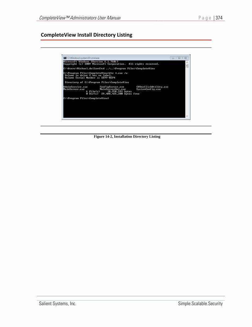
CompleteView™ Administrators User Manual P a g e | 374
Salient Systems, Inc. Simple.Scalable.Security
Figure 14-2, Installation Directory Listing
CompleteView Install Directory Listing
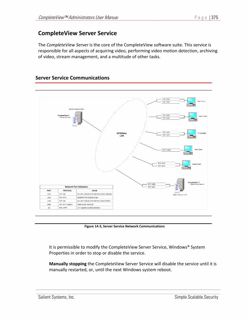
CompleteView™ Administrators User Manual P a g e | 375
Salient Systems, Inc. Simple.Scalable.Security
CompleteView Server Service
The CompleteView Server is the core of the CompleteView software suite. This service is responsible for all aspects of acquiring video, performing video motion detection, archiving of video, stream management, and a multitude of other tasks.
Figure 14‐3, Server Service Network Communications
It is permissible to modify the CompleteView Server Service, Windows® System Properties in order to stop or disable the service.
Manually stopping the CompleteView Server Service will disable the service until it is manually restarted, or, until the next Windows system reboot.
Server Service Communications

CompleteView™ Administrators User Manual P a g e | 376
Salient Systems, Inc. Simple.Scalable.Security
Manually disabling the CompleteView Server Service will leave it disabled it until the service is manually re‐enabled. Once disabled, the service will not automatically restart upon successive Windows system reboots.
Figure 14‐4, CompleteView Server Service
Server Service Maintenance Tasks
The following maintenance tasks are available to the CompleteView™ Server Service:
Register the CompleteView Server Service as a Windows® System Service.
Unregister the CompleteView Server Service as a Windows® System Service.
Run the Server Service in "interactive mode", e.g. as a normal application.
Specify the TCP port where the CompleteView™ Server service listens for client requests.
Maintenance tasks for the Server Service are performed from the Windows® Command Shell by invoking MainServer.exe executable image in the CompleteView installation directory from a command line, along with the appropriate command line argument(s).
Server Service in Windows® Computer Management Console
Start>All Programs>Administrative Tools>Computer Management>Services and Applications>Services
Click to select CompleteView™ Server Service

CompleteView™ Administrators User Manual P a g e | 377
Salient Systems, Inc. Simple.Scalable.Security
Before performing a MainServer maintenance task from the Windows® Command Shell, ensure the Server Service is either not registered or not currently running as a Windows® System Service. From the Windows® ‘Computer Management Console’, verify that the ‘CompleteView Server Service’ is either stopped or absent; reference Figure 14‐6 above.
When run from a Windows® Command Line, MainServer.exe starts in interactive mode, performs the task requested by the /<arg1> /<arg2> arguments and exits. If invoked without any command line arguments, AdminService.exe starts in interactive mode and immediately exits. If invoked with the /<arg1> = /noservice, MainServer.exe starts and runs in interactive mode.

CompleteView™ Administrators User Manual P a g e | 378
Salient Systems, Inc. Simple.Scalable.Security
Example:
C:\Program Files\CompleteView>MainServer /<arg1> [/<arg2>]
Where:
/<arg1>= /<arg2>=
/register [/port{n}]
Registers the CompleteView Server Service as a Windows® System Service and adds it to the list of System Services in the Windows® ‘Computer Management’ Console. The optional /port{n} argument may be included in order to specify the TCP port CompleteView™ Server will use to listen for client connections where {n} represents the desired port number.
If the /port {n} argument is omitted AdminService will register using the default port, TCP 4255.
/<arg1>= /unregister Un‐registers the CompleteView CompleteView™ Server Service as a Windows® System Service and removes it from the list of System Services.
/<arg1>= /noservice Run the CompleteView™ CompleteView™ Server Service in "interactive mode", e.g. as a Windows® application.
Table 14‐3, MainServer Command Line Arguments

CompleteView™ Administrators User Manual P a g e | 379
Salient Systems, Inc. Simple.Scalable.Security
Un‐Register MainServer
To unregister MainServer as a Windows® System Service and remove it from the list of System Services in the Windows® ‘Computer Management’ Console:
a) From the Windows® ‘Computer Management Console’, verify that the ‘CompleteView ServerService’ is stopped; reference Figure 14‐6.
b) Open a Windows® Command Shell and change the current directory to the CompleteView installation directory.
c) At the command line prompt enter the ServerService ‘unregister’ command.
Example:
C:/Program Files/CompleteView/> MainServer /unregister
Where:
/ unregister Unregisters MainServer as a Windows® System Service and removes it from the list of system services.
Table 14‐4, MainServer Unregister Command
Upon command completion, the Server Service will be unregistered as a Windows® System Service and removed from the list of System Services in the Windows® ‘Computer Management’ Console.

CompleteView™ Administrators User Manual P a g e | 380
Salient Systems, Inc. Simple.Scalable.Security
Register MainServer
To register MainServer as a Windows® System Service and add it to the list of System Services in the Windows® ‘Computer Management’ Console:
a) From the Windows® ‘Computer Management Console’, verify that the ‘CompleteView Server Service’ is absent; reference Figure 14‐6.
b) Open a Windows® Command Shell and change the current directory to the CompleteView installation directory.
c) At the command line prompt, enter the ServerService ‘register’ command.
Example:
C:\Program Files\CompleteView>MainServer /<arg1> [/<arg2>]
Where:
/<arg1>=
/<arg2>=
/register
[/port{n}]
Registers the CompleteView Server Service as a Windows® System Service and adds it to the list of System Services in the Windows® ‘Computer Management’ Console. The optional /port{n} argument may be included in order to specify the TCP port Server Service will use to listen for client connections where {n} represents the desired port number.
If the /port {n} argument is omitted Server Service will register using the default TCP port, 4255.
Table 14‐5, MainServer Register Command
Upon command completion, the Server Service registers as a Windows® System Service and appears on the list of System Services in the Windows® ‘Computer Management’ Console.

CompleteView™ Administrators User Manual P a g e | 381
Salient Systems, Inc. Simple.Scalable.Security
When the optional ‘/port {n}’ argument is omitted Server Service will register using the default port, TCP 4255.
When the optional ‘/port {n}’ argument is included Server Service will register using the TCP port specified by {n}.

CompleteView™ Administrators User Manual P a g e | 382
Salient Systems, Inc. Simple.Scalable.Security
Reassign MainServer TCP Port
In order to re‐assign the MainServer TCP Port, the MainServer service must be un‐registered and then re‐registered.
To re‐assign the Server Service TCP Port:
a) From the Windows® ‘Computer Management Console’, verify that the CompleteView™ Server Service’ is ‘Stopped’; reference Figure 14‐6.
b) Open a Windows® Command Shell and change the current directory to the CompleteView installation directory.
c) At the command line prompt enter the Server Service ‘unregister’ command:
C:/Program Files/CompleteView/ServerService /unregister
d) Upon command completion a new command line prompt will appear.
e) At the command line prompt enter the Server Service ‘register’ command, where {n} represents the desired TCP Port number :
C:/Program Files/CompleteView/MainServer/register /port {n}
f) From the Windows® ‘Computer Management Console’, start the ‘CompleteView™ Server Service’; reference Figure 14‐6.

CompleteView™ Administrators User Manual P a g e | 383
Salient Systems, Inc. Simple.Scalable.Security
Run MainServer in Interactive Mode
To run MainServer in interactive mode:
a) From the Windows® ‘Computer Management Console’, verify that the ‘CompleteView™ Server Service’ is either stopped or absent; reference Figure 14‐6.
b) Open a Windows® Command Shell and change the current directory to the CompleteView installation directory.
c) At the command line prompt enter the MainServer ‘run’ command :
“C:/Program Files/CompleteView/MainServer”
Upon command completion the MainServer will be running in Interactive Mode, e.g. as a Windows® Application.

CompleteView™ Administrators User Manual P a g e | 384
Salient Systems, Inc. Simple.Scalable.Security
CompleteView Administrative Service
The CompleteView Administrative Service, AdminService.exe, runs as a Windows® System Service. AdminService enables Remote Software Updates and remote control of the CompleteView Server, Windows® System Service from Admin Console clients.
Figure 14-5, CompleteView Admin Service
It is permissible to modify the CompleteView Administrative Service, Windows® System Properties in order to stop or disable the service. The Administrative Service should only be stopped or disabled when remote software updates or remote control of the CompleteView Server service is not desired.
Manually stopping the CompleteView Admin Service will disable the service until it is manually restarted, or, until the next Windows system reboot.
Manually disabling the CompleteView Admin Service will leave it disabled it until the service is manually re‐enabled. Once disabled, the service will not automatically restart upon successive Windows system reboots
Changes to the Administrative Service, Windows® System Properties can be accomplished via the Windows® Administrative Tools, Computer Management console.

CompleteView™ Administrators User Manual P a g e | 385
Salient Systems, Inc. Simple.Scalable.Security
Start>All Programs>Administrative Tools>Computer Management>Services and Applications>Services
Figure 14‐6, Select Admin Service
Administrative Service Maintenance Tasks
The following maintenance tasks can be performed for the CompleteView Administrative Service:
Register the CompleteView Administrative Service as a Windows® System Service.
Unregister the CompleteView Administrative Service as a Windows® System Service.
Run the Administrative Service in "interactive mode", e.g. as a normal application.
Specify the TCP port where the Administrative service will listen for client connections.
Maintenance tasks for the Administrative Service are performed from the Windows® Command Shell by invoking AdminService.exe executable image in the CompleteView installation directory from a command line, along with the appropriate command line argument(s).

CompleteView™ Administrators User Manual P a g e | 386
Salient Systems, Inc. Simple.Scalable.Security
Example:
C:\Program Files\CompleteView>AdminService /<arg1> [/<arg2>]
Where:
/<arg1> [ /<arg2>]=
/register [ /port{n}]
Registers the CompleteView
Administrative Service as a Windows® System Service and adds it to the list of System Services in the Windows® ‘Computer Management’ Console. The optional /port{n} argument may be included in order to specify the TCP port AdminService will use to listen for client connections where {n} represents the desired port number.
If the /port{n} argument is omitted AdminService will register using the default port, TCP 4255.
/<arg1>= /unregister Un‐registers the CompleteView
Administrative Service as a Windows® System Service and removes it from the list of System Services.
/<arg1>= /noservice Run the Administrative Service in "interactive mode", e.g. as a Windows® application.
When run from a Windows® Command Line, AdminService.exe starts in interactive mode, performs the task requested by the /<arg1> /<arg2> arguments and exits. If invoked without any command line arguments, AdminService.exe starts in interactive mode and immediately exits. If invoked with the /<arg1> = /noservice, AdminService.exe starts and runs in interactive mode
Before performing an AdminService maintenance task from the Windows® Command Shell, ensure the AdminService is either not registered or not currently running as a Windows® System Service. From the Windows® ‘Computer Management Console’,

CompleteView™ Administrators User Manual P a g e | 387
Salient Systems, Inc. Simple.Scalable.Security
verify that the ‘CompleteView Administrative Service’ is either stopped or absent; reference Figure 14‐6, above.

CompleteView™ Administrators User Manual P a g e | 388
Salient Systems, Inc. Simple.Scalable.Security
Un‐Register AdminService
To unregister AdminService Service as a Windows® System Service and removes it from the list of System Services in the Windows® ‘Computer Management’ Console:
d) From the Windows® ‘Computer Management Console’, verify that the ‘CompleteView Administrative Service’ is stopped; reference Figure 14‐6.
e) Open a Windows® Command Shell and change the current directory to the CompleteView installation directory.
f) At the command line prompt enter the AdminService ‘unregister’ command:
“C:/Program Files/CompleteView/AdminService /unregister”
Upon command completion, the AdminService will be unregistered as a Windows® System Service and removed from the list of System Services in the Windows® ‘Computer Management’ Console.
Register AdminService
To register AdminService Service as a Windows® System Service and add it to the list of System Services in the Windows® ‘Computer Management’ Console:
d) From the Windows® ‘Computer Management Console’, verify that the ‘CompleteView Administrative Service’ is absent; reference Figure 14‐6.
e) Open a Windows® Command Shell and change the current directory to the CompleteView installation directory.
f) At the command line prompt enter the AdminService ‘register’ command :
“C:/Program Files/CompleteView/AdminService /register [/port {n}]”
Upon command completion the AdminService will be registered as a Windows® System Service and added to the list of System Services in the Windows® ‘Computer Management’ Console.
When the optional ‘/port {n}’ argument is omitted AdminService will register using the default port, TCP 4255.
When the optional ‘/port {n}’ argument is included AdminService will register using the TCP port specified by {n}.

CompleteView™ Administrators User Manual P a g e | 389
Salient Systems, Inc. Simple.Scalable.Security
Reassign AdminService TCP Port
In order to re‐assign the AdminService TCP Port, the AdminService must be un‐registered and then re‐registered.
To re‐assign the AdminService TCP Port:
g) From the Windows® ‘Computer Management Console’, verify that the ‘CompleteView Administrative Service’ is ‘Stopped’; reference Figure 14‐6.
h) Open a Windows® Command Shell and change the current directory to the CompleteView installation directory.
i) At the command line prompt enter the AdminService ‘unregister’ command :
“C:/Program Files/CompleteView/AdminService /unregister”
j) Upon command completion a new command line prompt will appear.
k) At the command line prompt enter the AdminService ‘register’ command, where {n} represents the desired TCP Port number :
“C:/Program Files/CompleteView/AdminService /register /port {n}”
l) From the Windows® ‘Computer Management Console’, start the ‘CompleteView Administrative Service’; reference Figure 14‐6.
Run AdminService in Interactive Mode
To run AdminService in interactive mode:
a) From the Windows® ‘Computer Management Console’, verify that the ‘CompleteView Administrative Service’ is either stopped or absent; reference Figure 14‐6.
b) Open a Windows® Command Shell and change the current directory to the CompleteView installation directory.
c) At the command line prompt enter the AdminService ‘run’ command :
“C:/Program Files/CompleteView/AdminService”
Upon command completion the AdminService will be running in Interactive Mode, e.g. as a Windows® Application.

CompleteView™ Administrators User Manual P a g e | 390
Salient Systems, Inc. Simple.Scalable.Security
CompleteView Configuration Server
The CompleteView™ Configuration Server, configserver.exe, runs as a Windows® System Service.
The Configuration Server is a centralized database containing the Video Client configuration for every user in the enterprise. In addition to the benefits offered by centralized storage of these configurations, it also grants users the ability to roam to any computer in the network on which the CompleteView Client is installed, while retaining its individual viewing layouts.
Figure 14‐7, CompleteView™ Config Server Service
The Config Server is also an important component in CompleteView's client update process.
Each CompleteView Client that utilizes the configuration server can be configured to check for newer client software during the login process. If a newer version of the client application is found, then the user will be prompted to update their client software. The actual process of updating the client software is entirely automatic and does not require user or administrator intervention.
The Config Server may be installed on any Windows‐based computer in the network, regardless of whether or not it is running the CompleteView Server application.
This application is installed by selecting the CompleteView Config Server component in the setup program.
It is permissible to modify the CompleteView Configuration Service, Windows® System Properties in order to stop or disable the service.

CompleteView™ Administrators User Manual P a g e | 391
Salient Systems, Inc. Simple.Scalable.Security
Manually stopping the CompleteView Configuration Service will disable the service until it is manually restarted, or, until the next Windows system reboot.
Manually disabling the CompleteView Configuration Service will leave it disabled it until the service is manually re‐enabled. Once disabled, the service will not automatically restart upon successive Windows system reboots
Changes to the Configuration Service, Windows® System Properties can be accomplished via the Windows® Administrative Tools, Computer Management console.
Start>All Programs>Administrative Tools>Computer Management>Services and Applications>Services
Figure 14‐8, Select Config Server Service

CompleteView™ Administrators User Manual P a g e | 392
Salient Systems, Inc. Simple.Scalable.Security
ConfigServer Service Maintenance Tasks
The following maintenance tasks can be performed for the CompleteView ConfigServer Service:
Register the CompleteView ConfigServer Service as a Windows® System Service.
Unregister the CompleteView ConfigServer Service as a Windows® System Service.
Run the ConfigServer Service in "interactive mode", e.g. as a Windows® application.
Specify the TCP port where the ConfigServer service will listen for client connections.
Maintenance tasks for the ConfigServer Service are performed from the Windows® Command Shell by invoking ConfigServer.exe executable image in the CompleteView installation directory from a command line, along with the appropriate command line argument(s).

CompleteView™ Administrators User Manual P a g e | 393
Salient Systems, Inc. Simple.Scalable.Security
Example:
C:\Program Files\CompleteView> ConfigServer /<arg1> [/<arg2>]
Where:
/<arg1> [ /<arg2>]=
/register [port{n}]
Registers the CompleteView
ConfigService as a Windows® System Service and adds it to the list of System Services in the Windows® ‘Computer Management’ Console. The optional /port{n} argument may be included in order to specify the TCP port ConfigServer will use to listen for client connections where {n} represents the desired port number.
If the /port {n} argument is omitted ConfigServer will register using the default port, TCP 4255.
/<arg1>= /unregister Un‐registers the CompleteView
ConfigService as a Windows® System Service and removes it from the list of System Services.
/<arg1>= /noservice Run the ConfigService in "interactive mode", e.g. as a Windows® application.
When run from a Windows® Command Line, ConfigServer.exe starts in interactive mode, performs the task requested by the /<arg1> /<arg2> arguments and exits. If invoked without any command line arguments, AdminService.exe starts in interactive mode and immediately exits. If invoked with the /<arg1> = /noservice, ConfigServer.exe starts and runs in interactive mode

CompleteView™ Administrators User Manual P a g e | 394
Salient Systems, Inc. Simple.Scalable.Security
Before performing a ConfigServer Service maintenance task from the Windows® Command Shell, ensure the ConfigServer Service is either not registered or not currently running as a Windows® System Service. From the Windows® ‘Computer Management Console’, verify that the ‘CompleteView ConfigService’ either is stopped or absent, reference Figure 14‐6, above.
Un‐Register ConfigServer Service
To unregister ConfigServer Service as a Windows® System Service and removes it from the list of System Services in the Windows® ‘Computer Management’ Console:
1. From the Windows® ‘Computer Management Console’, verify that the ‘CompleteView ConfigServer Service’ is stopped; reference Figure 14‐6.
2. Open a Windows® Command Shell and change the current directory to the CompleteView installation directory.
3. At the command line prompt enter the ConfigServer ‘unregister’ command :
“C:/Program Files/CompleteView/ ConfigServer/unregister”
Upon command completion, the ConfigServer will be unregistered as a Windows® System Service and removed from the list of System Services in the Windows® ‘Computer Management’ Console.
Register ConfigServer
To register ConfigServer Service as a Windows® System Service and add it to the list of System Services in the Windows® ‘Computer Management’ Console:
1. From the Windows® ‘Computer Management Console’, verify that the ‘CompleteView ConfigServer Service’ is absent; reference Figure 14‐6.
2. Open a Windows® Command Shell and change the current directory to the CompleteView installation directory.
3. At the command line prompt enter the ConfigServer ‘register’ command :
“C:/Program Files/CompleteView/ ConfigServer/register [/port {n}]”

CompleteView™ Administrators User Manual P a g e | 395
Salient Systems, Inc. Simple.Scalable.Security
Upon command completion, the ConfigServer will be registered as a Windows® System Service and added to the list of System Services in the Windows® ‘Computer Management’ Console.
When the optional ‘/port {n}’ argument is omitted ConfigServer will register using the default port, TCP 4255.
When the optional ‘/port {n}’ argument is included ConfigServer will register using the TCP port specified by {n}.
Reassign ConfigServer TCP Port
In order to re‐assign the ConfigServer TCP Port, the ConfigServer must be un‐registered and then re‐registered.
To re‐assign the ConfigServer TCP Port:
1. From the Windows® ‘Computer Management Console’, verify that the ‘CompleteView ConfigService’ is ‘Stopped’; reference Figure 14‐6.
2. Open a Windows® Command Shell and change the current directory to the CompleteView installation directory.
3. At the command line prompt enter the ConfigServer ‘unregister’ command:
“C:/Program Files/CompleteView/ ConfigServer /unregister”
Upon command completion a new command line prompt will appear.
4. At the command line prompt enter the ConfigServer ‘register’ command, where {n} represents the desired TCP Port number :
“C:/Program Files/CompleteView/ ConfigServer /register /port {n}”
5. From the Windows® ‘Computer Management Console’, start the ‘CompleteView ConfigService’; reference Figure 14‐6.

CompleteView™ Administrators User Manual P a g e | 396
Salient Systems, Inc. Simple.Scalable.Security
Run ConfigServer in Interactive Mode
To run ConfigServer in interactive mode:
1. From the Windows® ‘Computer Management Console’, verify that the ‘CompleteView ConfigService’ either is stopped or absent, reference Figure 14‐6.
2. Open a Windows® Command Shell and change the current directory to the CompleteView installation directory.
3. At the command line prompt enter the ConfigServer ‘run’ command :
“C:/Program Files/CompleteView/ ConfigServer”
Upon command completion the ConfigServer will be running in Interactive Mode, e.g. as a Windows® Application.

CompleteView™ Administrators User Manual P a g e | 397
Salient Systems, Inc. Simple.Scalable.Security
Appendices

CompleteView™ Administrators User Manual P a g e | 398
Salient Systems, Inc. Simple.Scalable.Security
Appendix – A, PTZ Camera Control Protocols
Analog Camera Control Protocols (EIA Standards RS‐422/485)
AD ASCII Continuous American Dynamics ASCII; Continuous commands
AD ASCII Make/Break American Dynamics ASCII; Start/Stop commands
AD Pelco P
Canon VC‐C4
Kalatel
Digital CompleteView™ Digital PTZ control for fixed analog or IP cameras
Panasonic WV‐CS850 Conv Panasonic Conventional
Panasonic WV‐CS850 New Panasonic New
Pelco ASCII For CM6x00 video matrix switch and CM9760
Pelco D
Pelco P
Philips Biphase
RVision
SAE
Samsung
Sensormatic For Sensormatic and American Dynamics cameras
Sony EVI‐D30/D31 Sony Visca protocol
Ultrak KD6 (Diamond) Ultrak; formerly known as the Diamond protocol
VCL
Vicon

CompleteView™ Administrators User Manual P a g e | 399
Salient Systems, Inc. Simple.Scalable.Security
IP Camera Control Protocols (EIA Standards RS‐422/485)
ACTi HTTP IP ACTi IP camera driver
ACTi Pelco D IP ACTi IP camera driver
ACTi Pelco P IP ACTi IP camera driver
AD Illustra
AD
Axis V2 IP Axis Communications V2 API
Axis V2 IP version 4.0 Axis Communications V2 API; Use for camera/encoder firmware
Bosch BiCom
Bosch OSRD
Bosch Pelco‐D
Brickcom
Canon
Digital CompleteView™ Digital PTZ control for fixed analog or IP cameras
FLIR Nexus (DLTV) IP, Nexus (IR) IP
Generic‐D Generic Dynacolor IP PTZ Protocol
Hikvision Speed Dome
Mobotix IP Mobotix 360 degree IP cameras
Panasonic IP All Panasonic cameras
Pelco API
Pelco
Samsung
Sony IP Continuous Move
Sony IP‐Move Sony IP‐Move
Sony Visca IP All other Sony cameras
Toshiba IK‐WB IP Toshiba IK‐WB01A/11A
Toshiba IK‐WB21A Toshiba IK‐WB21A

CompleteView™ Administrators User Manual P a g e | 400
Salient Systems, Inc. Simple.Scalable.Security
IP Camera Control Protocols (EIA Standards RS‐422/485)
Vivotek

CompleteView™ Administrators User Manual P a g e | 401
Salient Systems, Inc. Simple.Scalable.Security
Appendix – B, Generic IP Camera Drivers
CompleteView has been designed as a flexible platform for supporting IP imaging devices. Accordingly, a generic driver model is available that supports a basic functionality for most IP cameras.
Generic IP Camera for MJPEG
Repetitive HTTP requests for a JPEG image:
Enter the path* for a JPEG image on the camera. Examples include "image", "jpeg", and "axis‐cgi/jpg/image.cgi?camera=2".
Generic IP MJPEG Streaming Camera for MJPEG
An HTTP request for streaming JPEG images:
Enter the path* for an MJPEG stream on the camera. Examples include "image", "nphMotionJpeg", and "axis‐cgi/mjpg/video.cgi".
Generic IP RTSP Streaming Camera for MPEG‐4
RTSP control of MPEG‐4 video over RTP, both tunneled through HTTP. Enter the path* for an MPEG‐4 stream on the camera.
A URL path follows the domain name (and optional port number) and precedes the query string. For example, in the URL, "http://192.168.1.100:80/image?speed=10", "image" is the path. However, CompleteView’s use of "path" includes everything after the domain name (and optional port number), which also includes the query string, if present. Therefore, from the example URL, one may enter "image?speed=10" as the path. If one does not enter the path beginning with a slash character ("/"), as in our example, CompleteView™ provides one. For those rare cases where the camera does not allow a path, enter a single slash character instead of leaving the path field blank.

CompleteView™ Administrators User Manual P a g e | 402
Salient Systems, Inc. Simple.Scalable.Security
Appendix – C, Axis Event Camera Configuration
In order to function properly, On‐Camera Event Alerting must be configured in CompleteView™, along with the Trigger Data feature and alerting mechanisms in the camera. If streaming MJPEG only, access the configuration via HTTP.
To configure the Axis camera Trigger Data and the camera alerting mechanisms utilized by CompleteView™:
1. In the CompleteView™ camera configuration <IP> window, click the [Configure] button. A web browser will launch and automatically navigate to the cameras’ Basic Configuration page.
Axis Camera Basic Configuration Web Page
Navigate to: System Options > Advanced > Plain Config
Figure 14‐9, Axis Camera Basic Configuration
2. From the Axis camera Basic Configuration web page, navigate to the Plain Config page.

CompleteView™ Administrators User Manual P a g e | 403
Salient Systems, Inc. Simple.Scalable.Security
Follow the hyperlinks: System Options>Advanced>Plain Config
Axis Camera Plain Config Web Page
Select Image Group parameters
Figure 14‐10, Axis Camera Plain Config Page
3. On the Axis camera Plain Config web page, select the Image Group parameters to modify.
From the Select Group drop down menu, select Image. Click the [Select Group] button.
A screen containing the Image Group settings will appear

CompleteView™ Administrators User Manual P a g e | 404
Salient Systems, Inc. Simple.Scalable.Security
Axis Camera Image Group Settings
Figure 14‐11, Axis Camera Image Group Settings
4. In the Axis Camera Image Group parameters, Image IO parameters, select the Trigger data enabled checkbox.
5. In the Axis Camera Image Group parameters, Image IO Overlay parameters, select the User data enabled checkbox.
Trigger Data alarming works with Motion JPEG, MPEG4 video streams and cameras with FW 5.60 and lower. HTTP notification method is currently used only for MJPEG and for other stream types, event notifications are received over RTSP and do not require any additional configurations on the camera except for creating motion zones.

CompleteView™ Administrators User Manual P a g e | 405
Salient Systems, Inc. Simple.Scalable.Security
HTTP Notification Command Format:
CompleteView™ HTTP Command Format
Notification URL
http://[address]:[port]/axis‐event.cgi?camera=[camera]&event=[action]
Table 14‐6, CompleteView™ HTTP Command Format
CompleteView™ HTTP Command Variables
[address] IP address or fully qualified hostname of the CompleteView™ server
[port] CompleteView™ web service port (default=8080)
[camera] CompleteView™ camera number
[action] Command to CompleteView™
Table 14‐7, CompleteView™ HTTP Command Variables
CompleteView™ HTTP Commands
motion_on Initiate motion recording
motion_off Terminate motion recording
alarm_on Initiate alarm recording
alarm_off Terminate alarm recording
Table 14‐8, CompleteView™ HTTP Command Actions

CompleteView™ Administrators User Manual P a g e | 406
Salient Systems, Inc. Simple.Scalable.Security
Axis Camera Event Notification Setup
The Axis camera must be configured to send a URL based notification to CompleteView on the desired event. The Axis camera event alerting interface varies slightly across different camera firmware revisions. Please refer to Axis documentation for the camera being configured for specific instructions.
Identify the CompleteView™ server as the event recipient
Define Action Rules for each camera‐triggered event
To identify the CompleteView™ server as the event recipient
Axis Camera Events Configuration Web Page
Navigate to: Setup > Events > Recipients
Figure 14‐12, Events Configuration Web Page
1. On the Axis camera Setup web page, expand the Events menu and select Recipients.
2. Click [Add…]. The Axis camera Event Configuration/Recipient Setup dialogue will appear.

CompleteView™ Administrators User Manual P a g e | 407
Salient Systems, Inc. Simple.Scalable.Security
3. On the Axis camera Event Configuration/Recipient Setup dialogue, input the recipient parameters.
Axis Camera Event Configuration/Recipient Setup
Input recipient parameters
Figure 14‐13, Event Configuration/Recipient Setup
Event Recipient Parameters
Name Any unique descriptive name such as CompleteView™ Server
Type HTTP
URL http://[address]:[port]/axis‐event.cgi Where: [address] = CompleteView™ server IP address [port] = CompleteView™ web service TCP port
User Name User account name used to log onto the CompleteView™ server
Password User account password used to log onto the CompleteView™ server, the password must not be blank
Table 14‐9, Event Recipient Parameters

CompleteView™ Administrators User Manual P a g e | 408
Salient Systems, Inc. Simple.Scalable.Security
4. On the Axis camera Event Configuration/Recipient Setup dialogue, click [Test].
A popup window should appear and report Upload Successful.
5. Click [OK] to save and close the Event Configuration/Recipient Setup dialogue.
Setup the Axis Camera Action Rules
1. On the Axis camera Setup web page, expand the Events menu and select Action Rules.
2. Click [Add…]. The Axis camera Event Configuration/Action Rules Setup dialogue will appear.
Action Rules
Navigate to: Setup > Events > Action Rules
Figure 14‐14, Action Rules Setup

CompleteView™ Administrators User Manual P a g e | 409
Salient Systems, Inc. Simple.Scalable.Security
Action Rule Setup
Navigate to: Setup > Events > Action Rule Setup
Figure 14‐15, Action Rule Dialogue
Action Rule Parameters
Name Any unique descriptive name such as Motion On
Trigger Select the Axis camera trigger that will initiate this Action Rule
Type Set to Send Notification
Recipient Select the CompleteView™ server previously setup as Recipient
Message Optionally enter text to be used as a log file entry upon each Action Rule occurrence
Custom Parameter Each Action Rule requires two custom parameters
Where: [parm1] = Camera number [parm2] = CompleteView™ Recording action
Table 14‐10, Action Rule Parameters

CompleteView™ Administrators User Manual P a g e | 410
Salient Systems, Inc. Simple.Scalable.Security
Setup the Action Rule Custom Parameters
1. In the Axis camera Event Configuration/Action Rules Setup dialogue, click the [Add] button. An Action Configuration/Custom HTTP Parameter dialogue will appear.
2. In the Action Configuration/Custom HTTP Parameter dialogue, enter the settings for Custom parameter #1
3. Click [OK] to save and close the Action Configuration/Custom HTTP Parameter dialogue
4. In the Axis camera Event Configuration/Action Rules Setup dialogue, click the [Add] button. An Action Configuration/Custom HTTP Parameter dialogue will appear.
5. In the Action Configuration/Custom HTTP Parameter dialogue, enter the settings for Custom parameter #2
6. Click [OK] to save and close the Action Configuration/Custom HTTP Parameter dialogue
Custom [parm1] Custom [parm2]
Two custom parameters required for each Action Rule
Figure 14‐16, Action Rule Custom Parameters

CompleteView™ Administrators User Manual P a g e | 411
Salient Systems, Inc. Simple.Scalable.Security
The first Custom HTTP Parameter created for each action rule identifies the CompleteView™ camera affected by the HTTP notification. The custom parameter uses the camera number as specified by the CompleteView™ Camera Configuration <IP> window CameraID field.
Custom [parm1] Settings
Name “Camera”
Value The camera number as specified by the CompleteView™ Camera Configuration <IP> window CameraID field.
Table 14‐11, Action Rule Parm1 settings
The second Custom HTTP Parameter created for each action rule is the actual HTTP command sent to the CompleteView™ web server each time the Action Rule executes.
Custom [parm2] Settings
Name “Event”
Value This value is the HTTP command sent to the CompleteView™ web server each time this action rule executes. Where: motion_on = initiate motion recording motion_off = terminate motion recording alarm_on = initiate alarm recording alarm_off = terminate alarm recording
Table 14‐12, Action Rule Parm2 settings
Please refer to Table 12‐30, Camera Alarm Events Samples for more examples.

CompleteView™ Administrators User Manual P a g e | 412
Salient Systems, Inc. Simple.Scalable.Security
Appendix – D, Symmetry Analytics Setup
1. Enabling VCA events from Symmetry Cameras.
a. From the Web interface, select VCA, then Enable/Disable.
b. Check the Enable VCA checkbox and the desired features. Only the features
selected will activate. Read the text describing how selecting events will affect
performance.
Apply the settings then move on to defining each event (setting lines and zones, etc.).
Figure 14-17, Symmetry VCA Setup
2. Enabling VCA events for Symmetry cameras from Complete View. Enabling VCA
events in Complete View is done in the CompleteView Server Configuration application.
a. Select the Cameras branch from the desired sever root, then select the
Symmetry camera of interest.

CompleteView™ Administrators User Manual P a g e | 413
Salient Systems, Inc. Simple.Scalable.Security
b. Select the IP tab and check the Use On‐Camera Alerting checkbox. Next, click on
the <Configure Alerts…> button.
Figure 14-18, Symmetry CompleteView Alert Setup
c. Enable / disable the Events of choice and select the recording level (Alarm or
Motion).
Figure 14-19, Symmetry Alarm Event Selection
d. Make sure the schedule for the Symmetry camera of interest is enabled for
Alarm and/or Motion based on the settings in the On‐Camera Alerting.

CompleteView™ Administrators User Manual P a g e | 414
Salient Systems, Inc. Simple.Scalable.Security
e. The Post motion and Post alarm timings on the Motion/Alarm tab are used
when recording the triggered on‐camera events.
Figure 14-20, Symmetry Motion and Alarm Timings
3. Enabling DI events from Symmetry Cameras. Unlike the VCA events, interface setup
beyond simply enabling the events is required.
a. From the Web interface, select the IO Configuration then DI/DO.
b. Select the DI Resource Type.

CompleteView™ Administrators User Manual P a g e | 415
Salient Systems, Inc. Simple.Scalable.Security
c. Select the DI Trigger Type.
Figure 14-21, DI Event Setup
d. Select Event Configuration from the Web interface then HTTP.
e. Under HTTP Server Configuration, enter the address of your server (e.g.,
192.168.103.60) and the port number (e.g., 4052)
f. Select to Enable Logon information. Fill in the user name and password of your
server. NOTE: Reentering the password may be required.
g. The Request Message format depends on the device model.
For all NVC series models, enter
/camera=3?action=query&type=%event%&info=%alarm%
and for all IPX/IPN series models, enter
/camera=3?action=query&type=<eventtype>&info=Alarm (where <eventtype>
is di or do). The important part is the /camera=#, where # is the camera number
in CV.

CompleteView™ Administrators User Manual P a g e | 416
Salient Systems, Inc. Simple.Scalable.Security
Figure 14-22, Symmetry HTTP Server Setting & Command Line
h. Apply the changes.
i. Select Event Profile and add a profile (or modify an existing one).
j. Select Enable Profile then, under Configuration, select DI, the Channel (e.g., DI
#1) and Active status.
Figure 14-23, Symmetry Event Profile
k. Click on the <OK> button to exit.
2. Enabling DI events for Symmetry Cameras from Complete View. There are two main
steps involved in enabling DI events: 1) Enable Discrete Inputs triggers in the On‐
Camera Alert configuration, and 2) Enable the Web Server HTTP interface.
CompleteView™ Administrators User Manual P a g e | 417
Salient Systems, Inc. Simple.Scalable.Security
a. Select the Cameras branch from the desired sever root then select the
Symmetry camera of interest.
b. Select the IP tab and check the Use On‐Camera Alerting checkbox then click on
the <Configure Alerts…> button.
c. Enable / disable the Discrete Inputs event and select the recording level (Alarm
or Motion).
d. Select the desired server root node then the Web Server tab.
e. Check the Enable Web Server (HTTP) check box.
f. Enter the same port number as in the Camera DI setup (e.g., 4502).
Please refer to Table 12‐30, Camera Alarm Events Samples for more examples.

CompleteView™ Administrators User Manual P a g e | 418
Salient Systems, Inc. Simple.Scalable.Security
Appendix E – Sentry360 Fisheye Calibration
CompleteView allows for calibrating the area of focus on many Sentry360 fisheye cameras. Select the Sentry360 camera from the Cameras list in CompleteView Server Configuration, and click the General tab. From the Lens Type dropdown menu, select Sentry360.
Acknowledge the notification that Dynamic Resolution Scaling will be disabled for the camera to be adjusted.

CompleteView™ Administrators User Manual P a g e | 419
Salient Systems, Inc. Simple.Scalable.Security
Click the [Calibrate Fisheye] button.
Click and drag the field of view circle (in white) to encompass the desired area. Alternately, the axis coordinates and circle radius can be set manually by entering the desired values in the corresponding fields.
Click [Set] when done. The Sentry360’s field of view has now been set.

CompleteView™ Administrators User Manual P a g e | 420
Salient Systems, Inc. Simple.Scalable.Security
Appendix F – Vivotek Events Configuration Use the VIVOTEK Web interface to configure the camera events1 under Configuration >> Applications.
1(Audio detection & PIR not supported).
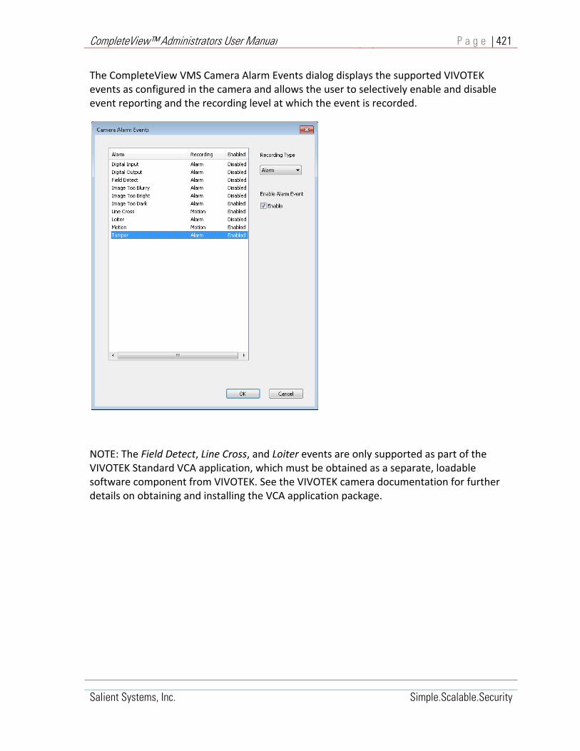
CompleteView™ Administrators User Manual P a g e | 421
Salient Systems, Inc. Simple.Scalable.Security
The CompleteView VMS Camera Alarm Events dialog displays the supported VIVOTEK events as configured in the camera and allows the user to selectively enable and disable event reporting and the recording level at which the event is recorded.
NOTE: The Field Detect, Line Cross, and Loiter events are only supported as part of the VIVOTEK Standard VCA application, which must be obtained as a separate, loadable software component from VIVOTEK. See the VIVOTEK camera documentation for further details on obtaining and installing the VCA application package.

CompleteView™ Administrators User Manual P a g e | 422
Salient Systems, Inc. Simple.Scalable.Security
Appendix G – FLIR Camera Configuration
G1. About the FLIR A310pt
The FLIR A310pt unit typically consists of two video sensors mounted on a single pan/tilt base. Consequently, the sensors always share the same elevation and bearing. One sensor provides a television (TV) image with zoom, focus, and iris control. The second sensor provides an infrared (IR) image with zoom and focus control.
G2. The FLIR A310pt and CompleteView
Add the sensors on the A310pt as you would any other camera in CompleteView. When adding different sensors from a single A310pt, each sensor is individually treated as a unique camera model. The TV sensor is added as the FLIR camera model A310pt DLTV and the IR sensor is added as model A310pt IR. This configuration allows the CV software to issue the proper camera control commands to each sensor. In the event an A310pt unit consists of two or more of the same sensor types, the ID field on the PTZ cameras tab in CompleteView will provide the unique instance ID for sensor control commands (zoom, focus, iris).
G3. Command Control Conflicts and Tour Considerations
The FLIR A310pt is a shared network device. When multiple users are connected to the A310pt, only one user at a time can issue commands to the unit. When a control command is requested by a CompleteView client station without the control token, CV automatically issues a request for camera control. After receipt of the unit control token, the CV client station is able control the unit. There may be a noticeable delay between each command as the interface waits for a response from the unit. When setting up a CompleteView Tour, it is important to remember that both sensors (TV & IR) are mounted on the same pan/tilt arm of the FLIR unit, and share the same set of preset point coordinates. While each sensor tour may specify a different set of preset times, the preset points are the same because they are stored in the Pan/Tilt module of the FLIR unit. If you have a large number of named presets you want to share between sensors in CompleteView, best practice is to install and configure one sensor (camera) first, clone that camera, and make the appropriate changes to the IP model and PTZ driver. For more information on the FLIR A310pt unit, please consult the FLIR Nexus IP Camera Configuration Guide available on the FLIR website.

CompleteView™ Administrators User Manual P a g e | 423
Salient Systems, Inc. Simple.Scalable.Security
Appendix H ‐ Active Directory® Connector
H1. Overview
This appendix assumes that you already have a live Active Directory implementation on your network and that you are familiar with the concepts, terms and tools surrounding it. Key Benefits of Integration with AD (Enterprise feature)
1. Active Directory can be leveraged for resolving issues related to the management of multiple passwords and accounts and greatly alleviates the account administration burden of the IT staff.
2. End‐users in Windows environments typically already employ Active Directory for their Windows login, thus options for achieving reduced or single sign‐on are expanded.
3. Authentication against a central directory such as Active Directory allows end‐users to have only one password to remember or change, eliminating the downtime and lost productivity associated with maintaining multiple passwords.
4. With end‐users employing only the Active Directory password, administrators’ account management tasks are streamlined and they realize a dramatic reduction in Help Desk calls, as end‐users no longer require them to perform password resets for forgotten passwords.
5. Coordinating disparate password policies is no longer an issue for administrators as Active Directory controls password quality, expiration, etc.
6. Authentication redirection to Active Directory provides strength and flexibility for optimizing compliance related activities, such as enforcing password policies that require passwords to be strong and changed regularly.
Prerequisites The following conditions should be met for each video server on which you wish to enable the AD connector.
1. The computer should be a member of the domain for which you have configured the AD connector. However, non domain joined servers connecting to AD are supported.
2. An Enterprise feature key must be installed. Limitations The following limitations exist in the current implementation of the AD connector.
1. Dynamic selection of domains is unavailable. 2. Supports only User and User Group objects.
Implementation
Performs dynamic authentication of users against the configured AD domain. Enumerates a user's group membership within the configured AD domain.

CompleteView™ Administrators User Manual P a g e | 424
Salient Systems, Inc. Simple.Scalable.Security
Access control remains within CompleteView. The Active Directory database schema is not extended.
H2. Dynamic User Authentication
User logs in as John.
The Server asks AD to authenticate John.
John fails AD authentication.
Unsuccessful Authentication
User logs in as John.
The Server asks AD to authenticate John.
John passes AD authentication; user group membership is enumerated.
Successful Authentication

CompleteView™ Administrators User Manual P a g e | 425
Salient Systems, Inc. Simple.Scalable.Security
H3. CompleteView Config Server
When the AD Connector for the Config Server has been enabled, dynamic authentication against AD is performed as users’ login to the CompleteView Client application. User credentials pass through the Config Server to each CompleteView Server that the user attempts to access.
John’s effective views.
Unsuccessful Authentication
John’s views are configured and stored in the Config Server. John inherits two view layouts from the Video Operators user group and one from the John user object.
John’s effective views.
Successful Authentication

CompleteView™ Administrators User Manual P a g e | 426
Salient Systems, Inc. Simple.Scalable.Security
H4. CompleteView Server
When the AD Connector for the Config Server has been enabled, dynamic authentication against AD is performed as users’ login to the CompleteView Client application. User credentials pass through the Config Server to each CompleteView Server that the user attempts to access.
John’s effective camera permissions.
Unsuccessful Authentication
Camera permissions are configured in the CompleteView Server. John inherits live view permission from the Video Operators and Video Supervisors user groups, playback permission from the Video Supervisors user group, and a PTZ priority level of '1' from the John user object.
John’s effective camera permissions.
Successful Authentication

CompleteView™ Administrators User Manual P a g e | 427
Salient Systems, Inc. Simple.Scalable.Security
Additional Resources Visit the Salient website, www.salientsys.com, for additional support and CompleteView
training:
Manuals & Documentation (http://www.salientsys.com/support/manuals‐and‐documentation/) – Includes Administrator’s Manual, Client User Manuals (including Video, Alarm and Web clients), How To Guides and Tips.
Online Tech Support (http://www.salientsys.com/support/– Get quick access to online tech support modules that cover the most frequently asked product questions, such as “Adding and Moving IP Camera Licenses.”
Training http://www.salientsys.com/support/training/ – we offer both online and
classroom training.
o CompleteView™ Online Certification ‐ Register online for access to interactive
training modules covering the Video, Alarm, Mapping and Web clients
o CompleteView™ Classroom Certification ‐ Our traditional classroom training is
available throughout the United States. Please visit the Salient website for link
to online training, training calendar, agenda and registration
Salient Systems 4616 W. Howard Ln. Building 1, Suite 100 Austin, TX 78728 512.617.4800 512.617.4801 Fax www.salientsys.com


