64


3 41156 0 3 h O L 4 L 2
ORN L-4522
Contract No. W-7405-eng-26
CHEMICAL TECH NO LOGY DI VIS ION
Chemical Development Section B
COMPLETION REPORT - EVALUATION OF THE USE OF PERMSELECTIVE MEMBRANES IN THE NUCLEAR INDUSTRY FOR REMOVING RADIOACTIVE
XENON AND KRYPTON FROM VARIOUS OFF-GAS STREAMS
R. H. Rainey, W. L. Carter, and S. Blumkin"
APRIL 1971
"Oak Ridge Gaseous Diffusion Plant.
OAK RIDGE NATIONAL LABORATORY Oak Ridge, Tennessee
operated by U N I O N CARBJDE CORPORATION
for the U. S. ATOMIC ENERGY COMMISSION


iii
CONTENTS
Page 7
Abstract .............................................. 1
1 . Introduction ........................................ 1
2 . Theory of Gas Separation by Permselective Membranes . ............ 7
3 . Materials and Procedure ................................. 12
4 . Laboratory Measurements of Permeabi Iity ...................... 16 4.1 Permeabilities o f Pure Gases .......................... 16
4.2.1 Experiments with Membrane Supported on Both Sides . . . . . . 20
Low-Pressure Side ............................ 20 4.3 Parameters Affecting Stage Separation Factors . . . . . . . . . . . . . . . 26 4.4 Effect of Temperature on Permeability Factors . . ............. 31
Effect of irradiation on Gas Permeation and Separation . ........
4.2 Effective Permeabilities of Component Gases i n a Mixture . . . . . . . 4.2.2
19
Experiments with Membrane Supported Only on the
4.5 35
5 . Design of Engineering-Scale Membrane Unit .................... 37
6 . Calculations of the Costs of Membrane Plants for Nuclear Industry
6.1 6.2
6.3
Applications ........................................ 37
Building ....................................... 45
from a Fuel Reprocessing Plant
Cost of Removing Xenon and Krypton from an LMFBR Cover Gas . . . Cost of Removing Noble Gases from a Reactor Containment
Cost o f a Permselective Membrane Plant for Processing Off-Gas
39
........................ 48
7 . References ......................................... 51


1
COMPLETION REPORT - EVALUATION OF THE USE OF PERMSELECTIVE MEMBRANES IN THE NUCLEAR INDUSTRY FOR REMOVING RADIOACTIVE
XENON AND KRYPTON FROM VARIOUS OFF-GAS STREAMS
R. Hi. Rainey, W. L. Carter, and S. Blumkin"
ABSTRACT
The effective permeabilities and separation factors o f krypton, xenon, and several other gases were measured using sheets of thin s i l i - cone rubber membrane having areas CIS large as 2 ft2; the pressure drop across the membrane was varied from 25 to 150 psi. Processes using such membranes were evaluated for removing the radioactive noble gases from (1) the off-gas from a plant for recovering used nuclear fuels, (2) a reactor containment building following a nuclear accident, and (3) the cover gas of a liquid metal fast breeder reactor (LMFBR). Radia- tion exposure o f the membrane would not be a limiting factor in the first two applications, but the LMFBR cover gas would have to be stored to allow the short-lived gaseous nuclides to decay before i t could be processed in a membrane plant. The costs of removing the noble gases from these systems were estimated.
1. INTRODUCTION
We have conducted a study o f some o f the parameters involved in removing the
radioactive noble gases from various off-gas streams by processes based on the use o f
thin silicone rubber membranes. This study consisted o f (1) laboratory measurements
o f effective gas permeabilities and separation factors, (2) radiation stabi Iity measure-
ments of assembled permeability units, and (3) engineering calculations for process
optimization and estimated equipment costs. Methods were developed for supporting
the membrane when the pressure drop across the membrane was high.
At the present time, only a few, comparatively small, nuclear power reactors
are i n operation. When long-cooled spent fuel elements from these reactors are dis-
solved for fuel recovery, the controlled venting o f the off-gas up tall stacks constitutes
*Oak Ridge Gaseous Diffusion Plant.

2
only a minor problem. In some cases, the noble gases are adsorbed on charcoal beds
and temporarily retained until the short-lived isotopes have decayed; the long-lived
Kr i s subsequently discharged to the atmosphere. Studies have been made of the 85
effects o f meteorological conditions and siting on the concentration of noble gases
that may be released from a reactor fuel processing plant.
privately operated, fuel processing plant i s authorized to release 3.3 x 10 Ci o f
radioactive noble gases per year under i t s certification. However, with the expected
rapid increase in the production of power by nuclear energy, the amount of Kr that
i s formed (Table 1 ) wi l l soon exceed this amount.
112 The presently operating, 6
85
Table 1. Predicted Generation of Radioactive Krypton to the Year 2000
Calendar Year 1970 1980 2000
150 940
0.6 120 1500
3 Installed nuclear capacity, 10 M w (electrical) 6
Annual generation rate of 85Kr, 10 C i 6
The "tolerance- level" for whole-body exposure of persons in nonrestricted areas
from al l sources i s 170 mrem per year. At present, individual exposures to released
noble gases are maintained at less than the tolerable level by the wide dispersal
of gases. Although these exposures are at present very low, i t may be desirable to
develop reasonably priced processes which can essentially eliminate this exposure.
The AEC regulations are being modified to require that exposures be minimized
as much as i s practical. Provisions for the isolation and subsequent permanent storage
of guseous fission products may, therefore, need to be made just as they are presently
made for nongaseous fission products.
At the end of a typical fuel cycle, Q 1000-Mw (electrical) reactor would con-
tain about 300 mill ion Ci o f radioactive krypton and about 400 mill ion Ci of radio-
active xenon. However, each gas contains several short-lived components so that,
after a 24-hr decay period, only about one mill ion Ci of krypton, chiefly 85
Kr
= 10.6 years),and 100 nii l l ion Ci of xenon, chiefly 133Xe (t1,2 = 5 days), would (t 1/2

3
remain. After about a month, the principal remaining activity would be due to the
Kr. 85
The hazards associated with the release of noble gas fission products are rec-
ognized by the USAEC; consequently, several methods for decreasing the amounts
that are released to the atmosphere have been i n ~ e s t i g a t e d ” ~ (Table 2). These
methods include:
ature, (2) adsorption on charcoal or molecular sieves at low temperature, (3) separation
by cryogenic disti Ilation, (4) extraction by hydrocarbons or chlorofluoromethanes,
(5) precipitation as clathrates or as fluorides, and (6) separation by permselective
membranes. Another alternative that has been considered is the injection of the
gases into porous underground media.
(1) adsorption on charcoal or molecular sieves at ambient temper-
4
The adsorption o f noble gases on charcoal or molecular sieves at ambient tem- 5
perature is the process that has been studied most extensively. This i s a simple
method for delaying the release o f the noble gases to the ahnosphere i n order to
allow the short-lived isotopes (primarily xenon) to decay. However, i t has certain
disadvantages such as: (1) large beds of charcoal are required; (2) the charcoal
burns readily, and molecular sieves are subject to explosion as the result o f local
heating of adsorbed gases by radioactive particles; and (3) the K r i s released to
the atmosphere instead o f being concentrated for permanent storage, The fire and
explosion hazards may be eliminated or minimized by suitable design or operational
procedures.
85
Adsorption on charcoal or molecular sieves at low temperatures permits the use
o f a smaller adsorption bed; however, the fire hazard remains. Additional dis-
advantages are the costs incurred i n cooling the bed and the explosion hazards
associated with the adsorption of the ozone that i s produced by the irradiation of
oxygen. Materiais that would freeze or condense must be completely removed from
the gas prior to i t s injection into the bed in order to prevent plugging of the equip-
ment. One gas, N20, which has been particularly troublesome i n this system, may

4
o\
0.
8.
o\
a, > .- x
Ll
$ 2 Y
s
a L 0
$ L
U
b
-5 U
u I
v)
U c
v) c

be removed with hydrogen and a
In the cryogenic separation,
6 palladium catalyst.
the noble gases and part of the air, or other carrier
gas, are f i rs t liquefied. Then the noble gases are separated from the bulk gases and
are concentrated by fractional distil lation. This process has been demonstrated at a
gas flow rate equal to that of the off-gas from a 3-ton-per-day fuel processing plant,
but at about one-fifth the radioactivity level.
operations, water and other gases that would form solids must be essentially removed
prior 1.0 the treatment of the noble gases. Solids in the system cause physical dif-
ficulties, and the presence of liquid ozone, which i s formed from the radiolysis o f
oxygen, creates an explosion hazard.
6 As i n al l of the low-temperature
The study of the separation of noble gases from air by absorption i n (or extraction
by) chlorofluoromethanes (Freon) has progressed to the nonradioactive p i lot-plant
This i s a very versatile system; since the operating temperature (- 20OF) 7,8 stage.
i s higher than that used in low-temperature charcoal bed adsorption or the cryogenic
distillation methods (-29OoF), the concentration of condensable gases such as water
need not be extremely low. Operation at, or near, ambient temperature appears to be
possible and is, therefore, being investigated. Ai though degradation o f the solvent
due to radiation is not expected to be limiting, i t has not been investigated. Possible
carry-over of Freon or degradation products into reactor systems such as a sodium-
cooled or a molten-salt reactor could cause difficulty.
9 10 Precipitation of the noble gases as clathrates or as fluoride compounds has
been proposed. Although this fype of process would yield a solid product, which
would simplify permanent storage, i t is not efficient because of the very low concen-
trations of noble gases i n the off-gas streams and hence does not appear to be
economically attractive. On the other hand, such a process may be quite useful for
solidifying concentrated gases for storage.
The separation o f noble gases by the use of permselective membranes has been
proposed as an alternative to the processes described above, and was the subject of
our investigation. 1 1
This process has a long history. More than 100 years ago,

6
observed that various gases penetrated natural membranes at different 12,13
Mitchel I
rates.
practicable until methods were developed for preparing very thin, hole-free sheets
of modern polymers. The range of the application of this technique to industrial
separations may be deduced from the papers presented at the Symposium on Membrane 14
Processes for Industry
However, industrial separations o f gases by this technique did not become
held in Sirmingham, Alabama, i n 1966.
15-17 Although any polymer may be used for the separation of gases, s i I i cone
rubbers have the highest permeabi lities measured thus far; also, they yield high
gas separation factors. 18-21
Robb proposed the use of permselective membranes for 21 22
while Holmes separating xenon and krypton from air, proposed the use of such
membranes for removing noble gases in the atomic energy industry. Of course, the
use of these membranes i n an industrial process would be dependent on the avail-
ubi l i ty o f large, very thin sheets that are free of holes and adequately supported to
withstand large pressure drops. Prior to our entry into this study, the General
Electric Research and Development Center at Schenectady, New York, had developed
methods for preparing 1- by 2-ft sheets, about 1.7 mi ls thick, which were supported
so they could withstand a pressure o f at least 150 psi.
The objective o f our study was to investigate the effects of various parameters,
such as pressure drop across the membrane, percentage of gas passing through the
membrane, direction of flow of gas in a separations unit, and radiation and chemical
degradation of the membrane, on the permeabilities and the separation factors o f
the gases. A mathematical model for the diffusion o f gases in a separations unit based
on gas flow and diffusion equations was developed for comparison with experimental
observations. Several partial ly optimized cascade designs were developed for various
process applications, and costs of selected processes were estimated.
Many people contributed to this study. A. Dounoucas, H. D. Briggs, and D. G.
Wi l l is o f the General Electric Research and Development Center at Schenectady,
New York, developed and bui l t the membrane test units that we used; i n addition,
they very generously shared their techniques and experience. E. Von Halle of the

7
Oak Ridge Gaseous Diffusion Plant developed some of the mathematical relationships
used in this study; he also helped design and optimize membrane cascades and evaluate
data. D. E. Fain, also o f the Oak Ridge Gaseous Diffusion Plant, measured the effect
of temperature on permeability reported i n Sect. 4.4. Students from the School o f
Chemical Engineering Practice, Massachusetts Institute of Technology, under the
direction o f S. M. Fleming and H. 0. Cochran, helped to collect and evaluate experi-
mental data. R. C. Lovelace, R. H. Shigley, C. L. Roggenkamp, T. E. Harmon, and
A. H. Confer conducted many of the experiments. L. M. Ferris reviewed the draft of
this report and made many helpful suggestions that have improved the clarity of our
presentation.
2. THEORY OF GAS SEPARATION BY PERMSELECTIVE MEMBRANES
The transport of a gas through a permselective membrane requires the following
steps: (1) contact of the gas with the high-pressure surface of the membrane, (2)
dissolution of the gas i n the membrane, (3) diffusion of the gas through the membrane,
and (4) evaporation of the gas from the low-pressure surface of the membrane. This
process i s quite different from the transport of gases through a porous membrane (Fig. 1).
With porous membranes, the separation of gases i s proportional to the ratio o f the
square roots of their molecular weights. With a permselective membrane, the separation
i s proportional to the ratio of the products of the solubilities in, and the diffusivities
through, the membrane.
Most gases i n polymers have been found to obey Henry's law of solubility:
C. = K p. , I I
and Fick's Law for diffusion:
d C. I
i d t x ' N. =-AD I
where

8
O R N L - D W G 70-14509
O R D I N A R Y POROUS M E M B R A N E
0 A I R
0 @
A I R 0 0 (SI ightly Modified
04- N i t r o g e n
M o l e c u l e s p a s s t h r o u g h o p e n i n g s
PERMSELECTI V E M E M B R A N E
, Molecule i n solution * of O x y g e n
H i g h e r P e r c e n t a g e
0
Lower Pressure
@
0 e
Molecule going into solution with membrane
Molecule corning out of solution with membrane
I Perrneaoility = Solubility ) x I Rate of Diffusion I
Fig. 1. Diagram Explaining Differences in fhe Actions of Gases Flawing Through (a) a Porous and (b) a Permselective Membrane.

9
C. = concentration of gas i in the membrane, I
K = Henry's law constant, I
pi - partial pressure of gas i,
N. = flow rate of gas i through the membrane,
A = membrane area,
D. = diffusivity of gas i in the membrane material,
1
I
t" = distance into the membrane.
At a given temperature, i f we assume that K i s independent of the thickness of the
membrane, substituting Eq. ( 1 ) into Eq. (2) and solving the differential equation
yields AK.D.Ap.
I 1 I
t N. = t I
(3)
in which
Ap. = the difference in the partial pressures of component i on the two sides I
of the membrane,
t = thickness of the membrane.
If we define the permeability factor of a particular gas, P., as I
P. = K.D. I 1 I
substituting Eq. (4) into Eq. (3) and rearranging yields:
N.t I p E - .
i AApi
The units used in our study were:
N = ml (STP)/sec,
t = cm, 2
A = c m ,
bpi = cm Hg.

10
Flow through a permselective membrane i s accompanied by a pressure drop across
If this pressure drop I s not extremely high (e.g., not more thun several the membrane.
hundred atmospheres), the permeability factor should be a constant for a given mern-
brane and gas.
The permeation of gases through a permselective membrane has been shown to be 23
related to the crit ical temperatures of the gases. Thus i t i s possible to estimate
the permeability factor of a gas that has not previously been measured i f the per-
meability factor o f a similar gas and the respective crit ical temperatures are known.
Our test equipment was arranged as follows:
..I-------------
Extract +- 1 - I + Extract (countercurrent) (cocurrent)
The gases to be separated were fed to one side of the membrane at the upper
left of the unit. Fractions of the gases passed through the membrane (extract); the
remainder (raffinate) was removed from the upper right side of the unit. If both the
extruct and the raffinate were removed from the same end of the unit, the gas flow
was designated as cocurrent. If the extract was removed from the same end of the
unit as the feed entered, the flow was designated as countercurrent.
We assumed that there was no concentration gradient perpendicular to the
membrane since this distance was only about 3 mm and the unit contained screens
which mixed the gas. However, with gas mixtures, a concentration gradient did
exist along the membrune (in the "y" direction) because of the different rates of
transport of gases in the mixture through the membrane. This effect, along with the
effect of the membrane backing (support), precluded the direct determination o f
permeability factors, At each set o f experimental conditions an effective permeability
could be determined, using Eq. (5), from measured values of N. and @.. In cal-
culating Ap., we assumed that the changes in gas concentrations along the membrane
were linear. For gus mixtures,in which one component was present at a concentration
I l
I

of less than 0.5%, the partial pressure of the minor component on the high-pressure
sidle of the membrane was taken as the average o f i t s concentrations i n the feed
and in the raffinate. The concentration of this component in the extract stream was
used as i ts partial pressure on the low-pressure side of the membrane.
We defined "cut" as the flow rate of the extract multiplied by 100, divided by
the flow rate o f the feed. At zero cut, there would be no flow through the membrane;
therefore, no concentration gradient would exist i n the "y" direction.
The stage separation factor for a two-gas mixture i s defined as:
where
E l = mole fraction o f noble gas i n gas that permeated the membrane,
E
R R2 = mole fraction o f carrier gas in gas that did not permeate the membrane.
= mole fraction of carrier gas i n gas that permeated the membrane,
= mole fraction o f noble gas i n gas that did not permeate the membrane, 2 1
In our system, the mole fraction of the carrier gas was greater than 0.99 i n both the
extract and the raffinate (E and R ); therefore, the stage separation factor of the
noble gas was approximately equal to the ratio of the concentration of noble gas in
the extract to its concentration i n the raffinate. With radioactive tracers, the
stage separation factor was assumed to be the ratio of the radioactivities of the two
exiting gas streams.
2 2
The stage separation facfor of two gases at zero cut and zero pressure on the
low-pressure side of the membrane,(i.e., Q ), may also be shown to be the ratio of
the permeability factors of the two gases: 0
- -- CY = SF p2 *
o (zero)

12
Our system operated at approximately a ospheric pressure on the low-pressure side. 24
The effect of this back pressure on the separation factor has been shown by Blumkin
to be:
ct cy" 0
r 1 f R(Q - I ) 0
where R i s the low pressure divided by the high pressure and 0" i s the separation
factor at zero cut.
S. H. Jury 25
developed a model for the fractionation of gas mixtures using perm-
selective membranes; this model takes into uccount (1) longitudinal diffusion i n the
bulk gas streams and plumbing connections, (2) normal diffusion through the membrane
and its backings, (3) mixing effects due to turbulence-promoting screens inserted
in the bulk gas streams, and (4) the two possible modes of operation, cocurrent and
countercurrent flow. Analysis of the steady-state madel leads to a set of ordinary
differential equations that must, subject to appropriate limiting conditions, be solved
simultaneously to evaluate experimental results or to design new equipment. A few
tests of the model were made using experimental data. These tests showed that
additional experimental data wi l l be required before a detailed analysis o f the
engineering parameters can be made.
Recently, Stern and Walawender 26
Parameters,'' which wi l l be very valuable to future investigators in this field.
published an "Analysis of Membrane Separation
3. MATERlALS AND PROCEDURE
The membrane used in our study was prepared by the General Electric Company.
It had the following composition:
100 parts (by weight) methylphenyl polymer containing 5.3 **
mole %** phenyl groups and 0.1 male %
specific gravity = 0.98.
44 parts (by weight) fumed silica.
vinyl groups;
;b *, Calculated as the percentage of total substituent groups on the silica.

13
Volume fraction of f i l ler (calculated) = 0.164.
It had been partially cured with 0.5% bis-2,4-dichlorobenzoyl peroxide and then
heated at 150°C for 1 hr i n an oven. It was supplied i n the form of 30- by 60-cm
sheets that were about 4.6 x 10
the membrane was bonded between two 0.01-cm-thick sheets of Dacron fibers.
However, some data were obtained with membrane supported by Dacron on only one
side (the low-pressure side). The membrane described above, with i t s backing, was
supported on polyester screens, which acted as gas turbulence promoters. The test
packages (i.e., the membrane, mats, and screens) were sealed around the edges with
a silicone rubber bonding material (RTV-I I ) , which served to secure the package
between stainless steel plates. Gas inlets and/or outlets were fitted onto the plates.
-3 cm thick and free of holes. In most of our work,
The equipment for regulating the pressure and the flow of gas, determining and
recording the radioactivities of the gas streams, and recycling the used gas to the
feed vessel is shown in Figs. 2 and 3. The gases normally used in the experiments
were oxygen, nitrogen, or argon, either pure or mixed with less than 0.5 Val %
krypton or xenon containing
Carbon dioxide was used in a few experiments.
85 133 Kr or Xe, respectively, as a radioactive tracer.
Each gas under skrdy was fed to the test unit at a regulated pressure. The down-
stream side of the membrane was maintained at atmospheric pressure. The cut (i.e.,
the percentage of gas passing through the membrane) was varied by changing the
rate at which gas was removed from the high-pressure side of the membrane.
Both the extract and the raffinate streams were continuously routed through
small duplicate vessels mounted over scintillation crystals in shielded containers.
The radioactivities o f the two streams were thus monitored during alternate 1O-sec
intervals by using a modified 400-channel Victoreen analyzer, which was adjusted
to count only the energy o f the principal gamma ray emitted by the tracer gas. The
accumulated counts were automatically printed out for evaluation. This type o f
experiment was continued unti l the radioactivity levels of the gas streams were con-
stunt to within about 1%.


ORNL-DWG 68-8568
Y - t W OFF-GAS
DIFFERENTIAL @ GAGE
1L EXPANSION BLADDER
PRESSURE
4 +GAS CYLINDER
W- OFF-GAS cn + VACUUM
RECYCLE TANK
I
I - FROM
RECYCLE TANK
FEED TANK FEED
PRESSURE PRESSURE
? PRESSURE
EXTRACT RAFFINATE PRESSURE PRESSURE
VACUUM
GAS CYLINDER
EXTRACT COUNTER
RAFFINATE SYSTEM
7 1-0~~-GAS c b
EXTRACT
7 J 0
OFF-GAS El
RAFFl NATE COUNTER
VOLUMETER L SAMPLE BULB
Fig. 3. Diagram of Laboratory Equipment for Determining the Effective Permeabi l i t ies and Separation Factors of Gases by Using a Permselective Membrane.

16
On exiting from the counting chambers, the gases were accumulated i n separate
VoI-U-Meters (Brooks Instrument Company, inc.). An accurate flow rate for each
was determined by measuring the time required to collect a volume of the gas in
the appropriate calibrated collection cylinder. When the Vol -U-Meters were full,
the gases were transferred into a recycle tank containing a flexible plastic liner.
Each test gas could be repressurized by introducing nitrogen outside of the liner and
could then be returned to the feed tank. In this way, the feed gas could be main-
tained at a constant composition for a series of experiments.
4. LABORATORY MEASUREMENTS OF PERMEABILITY
4.1 Permeabilities of Pure Gases
The effective permeabilities of nitrogen, oxygen, and argon were determined at
room temperature,and at about 30% cut, using membrane that was supported between
two sheets of Dacron mat. The data obtained are shown in Fig. 4; the values for
nitrogen and oxygen are about a factor of 2 lower than the permeability factors
obtained by Robb,
not bonded to a support material. Robb obtained permeability factors of 28 x 10
21 who used a similar membrane; however, Robb's membrane was
-9 , . .
-9 60 x 98 x 10 , and 203 x lom9 for nitrogen, oxygen, krypton, and xenon,
respectively. The results o f the present study are in agreement with those of H. P.
Briggs, o f the General Electric Company, in showing that the effect of the support
material generally i s to make the effective permeability lower than the permeability
factor. Also, with a support material present, the effective permeabil i ty decreases
regularly with increasing pressure drop across the membrane (Fig. 4).
27
27 Briggs and his co-workers have shown that about 40% of the loss in effective
permeability at a pressure drop of 150 psi may be recovered by bonding the membrane
to a properly selected mat on only the low-pressure side and by proper selection of
support and turbulence promoting screens. They tested numerous backing materials
and supporting screens i n order to select a combination of materials that would give
the lowest flow resistance in the directions normal and parallel to the membrane.

17
0
+-
~ NITROGEN 't-
ORNL-DWG 67--11212AR
50 100 PRESSURE DROP ACROSS MEMBRANE ( p s i )
150
Fig. 4. Effect of Pressure Drop Across the Membrane on the Effective Perme- abilities of Argon, Nitrogen, and Oxygen. Membrane supported on both sides. About 30% cut.

18
The tests consisted in measuring the permeation of oxygen under pressure drops
ranging from 15 to 150 psi for each support combination. Using similar membrane
samples, some backing materials exhibited low permeation rates, whereas other
samples of the same materials, but having different thicknesses and weights, exhibited
higher permeation rates. Also, some of the samples were found to have a satisfactory
porosity normal to their surfaces under low pressure drops but were relatively non-
porous (i.e., showed a decrease in the permeation rate) as the pressure drop across
the membrane increased to 150 psi. In many o f the tests, the membrane showed
evidence of being depressed, or deformed, by the openings i n the supporting screen.
The effective permeabilities obtained when these supporting materials were used were
generally lower than those obtained with the other materials, and they decreased
as the pressure increased. Deformation of the support mat into the openings i n the
screen tends to reduce the cross-sectional volume of the screen that i s available for
gas flow; i t also creates many points of high stress. Therefore, the fibers of the sup-
port mat must have sufficient strength to span the openings i n the screen, as well as
exhibit high resistance to compression.
membrane.
However, the fibers must not puncture the
27 The most favorable permeability data reported by Briggs were obtained with a
0.018-cm-thick mat, weighing 30 g/m , that was composed o f polyester fibers and a
polyvinyl binder. The effective permeability of oxygen with this material was 56.5
x 10
unbonded membrane.
across the membrane was increased to 150 psi.
2
-9 -9 , CIS compared with the permeability factor of 60 x 10 obtained with an
No decrease in permeability occurred as the pressure drop
27 Briggs and his co-workers conducted a similar study to choose the most effective
screen support. They investigated screens made of polyester monofilament or stain-
less wire having various diameters and sizes of mesh openings. They found that two
screens on the low-pressure side o f the membrane provided the most satisfactory
arrangement. A polyester screen (0.028-cm threads, 60 threads/cm, 0.081 -cm mesh
opening, 55% open area) was positioned adjacent to the support mat, and a stainless
steel screen (0.019-cm wire, 61 wires/cm, 0.087-cm mesh openings, 67.2% open area)

19
was placed behind the plastic screen. These two screens had similar fiber spacings,
but the stainless steel wire was smaller than the plastic filament, thereby resulting
i n a larger open area. The stainless steel screen could not be used immediately
adjacent to the mat because i t contained sharp wire points that would puncture the
membrane. Also, it had a tendency to buckle under high stress conditions to form
sharp ridges, which would also puncture the membrane.
A polyester screen (0.1 J4-cm threads, 44.5 threads/cm, 0.1 J4-cm mesh opening,
58% open area) was included on the high-pressure side of the membrane to induce
turbulent flow. The large, smooth fibers of this screen exhibited a negligible
tendency to puncture the unprotected rubber membrane.
4.2 Effective Permeabilities of Component Gases in a Mixture
The effective permeability o f each gas in mixtures composed of low concentrations
of krypton and xenon i n air or other gases such as helium or argon was of particular
interest i n this work. Consequently, laboratory studies were carried out in which we
measured the effective permeability of each gas in mixtures containing less than
0.5% xenon or krypton in nitrogen or oxygen. Data were obtained using a membrane
supported on both sides by Dacron mats and also with a membrane supported by
Dacron only on the low-pressure side. Since only the feed stream and the exit streams
from the membrane unit could be analyzed, the composition of the gas on the high-
pressure side o f the membrane was assumed to be the average of the feed and raffinate
streams, and the composition o f the gas on the low-pressure side was assumed to be
that of the extract stream, Since there was such a small change in the concentration
o f carrier gas flowing through the unit, we could not measure changes in i t s effective
permeability due to the presence o f xenon or krypton. In contrast, the calculated
effective permeabilities for xenon and krypton varied with pressure drop across the
membrane, the percentage o f the gas permeating the membrane (cut), and the identity
of the carrier gas.

20
4.2.1 Experiments with Membrane Supported on Both Sides
In these experiments, the low-pressure side of the membrane was at atmospheric
pressure, the pressure on the high-pressure side was varied from about 25 to 150 psi,
and approximately 40% of the gas was allowed to pass through the membrane. The
effective permeabilities of xenon in oxygen were much greater than those obtained
using nitrogen as the carrier gas (Fig. 5). Moreover, over a wide range of pressure
drops, the effective permeability of xenon at about 40% cut was proportional to the
effective permeability o f the carrier gas (Fig. 6).
Extrapolation of plots of the effective permeability o f a component of a gas
mixture vs cut to zero cut (i.e., to zero flow of gas through the membrane) eliminates
the effect o f the carrier gas. Data obtained with krypton-oxygen and krypton-
nitrogen mixtures are shown in Figs. 7 and 8. At zero cut, the effective permeabilities -9 -9
at 25 psi and 48 x 10 of krypton in oxygen were about 54 x 10 at 100 psi -9
(Fig. 7); in nitrogen, the corresponding values were approximately 56 x 10
48 x lom9 (Fig. 8). The decrease in effective permeability with increase i n pressure
drop across the membrane i s due to the presence of the support material. As seen
in Figs. 7 and 8, no significant differences in the effective permeabilities were
produced by changing from cocurrent to countercurrent flow conditions.
and
4.2.2 Experiments with Membrane Supported Only on the Low-Pressure Side
The effective permeabilities of krypton, using nitrogen as the carrier gas (Fig. 9),
were higher when the membrane was supported only on the low-pressure side than
when the membrane was supported on both sides (Fig. 8); the effective permeabilities
also were less sensitive to pressure drop across the membrane. Use of countercurrent,
rather than cocurrent, flow resulted i n significant differences i n the effective permea-
bilities, especially when the pressure drop across the membrane was only 25 psi (Fig. 9) .
One type of nuclear power reactor fuel i s made by dispersing fissionable and
fertile materials i n graphite. A proposed process for recovering this used fuel in-
volves burning of the graphite. Since the noble gases would be expected to be

21
100
90
80
70 X
>-
_I
Q
CT w
v
- 60
m -
50
a 2 40 - t- o w
W 30
20
10
0
ORN L- DWG 67- 11210A R
... -- ........
- ....... __
.......
0 25 50 75 100 125 150 PRESSURE DROP ACROSS MEMBRANE (ps i 1
Fig. 5. Effect o f the Currier Gas on the Effective Permeability of Xenon in a Mixture Containing Less than 0.5% Xenon in Nitrogen or Oxygen. Membrane supported on both sides. About 40% cut.

22
Of? N L-DWG 67-41 214AR h
m 0 X 80 v
z 0 z W X LL 0
60 - J - m a w 2 QI W Q.
: 40 t- o w LL LL w
0 25 psi 100 psi
A 150ps i
/ /
30 20
0 10 20
EFFECTIVE PERMEABILITY OF CARRIER GAS ( ~ 1 0 ~ 1
Fig. 6. Effect of the Permeability of the Carrier Gas on the Effective Perme- abil ity o f Xenon i n Mixtures Containing Less than 0.5% Xenon i n Nitrogen, Oxygen, or Helium. Membrane supported on both sides. About 40% cut.

23
---' A COCURRENT FLOW 0 COUNTERCURRENT FLOV
60
5 0
cr- 2 .3
2 sl
l5
r Y
m
2 40 &
t-
LL u- Y
30
27
20
1-
. . . . . . . . . .
--z
25 psi
A
0 10 20 30 40 50 60 70 80 30 PERCENTAGE OF GAS PERMEATING THC MEMBRANE
Fig. 7. Effective Penneabilities of Krypton and Oxygen as a Function of Cut (< 0.5% Krypton in Oxygen). Membrane supported on both sides.

24
ORNL-DWG 68- 6569A2 R
0-l- 0 X
>- I- -I
- v
- - m a W 2 lx w a w > I- o w LL LL w
-
60
50
40
3c
2c
IC
I___
I COUNTER-
COCURRENT CURRENT 0
0
% \ \ ......
\ O \ 0
‘ t KRYPTON \
\
e 9- NITROGEN
a a 0- c
0 0
o 25 psi
rn 100 psi
0 10 20 30 40 50 60 70 80 90 400
PERCENTAGE OF GAS FLOWING THROUGH MEMBRANE
Fig. 8. Effective Permeabilities of Krypton and Nitrogen as a Function of Cut and Pressure Drop Across the Membrane. Membrane supported on both sides.

25
I - .......... 1 ORNL-DWG 70-14510
7- I I
1 e COUNTERCURRENT m 0 COCURRENT
KRYPTON
......... ................ 1-.- I 1 1 -......I...._.. 40 20 30 40 50 60 70 SO 90
PERCENTAGE OF GAS FLOWING rHROUGH THE MEfv1BRANE 0
Fig. 9. Effective Permeabilities of Krypton and Nitrogen as Q Function of Cut, Pressure Drop, and Flow. Membrane supported only on low-pressure side.

26
released during burning, a few experiments were conducted to determine the effect
of C02 on the permeability of krypton. Results obtained by using a mixture of
nitrogen, krypton, and 1.5% CO showed that the permeability o f the krypton was
within the l imit of error of the data at pressure drops across the membrane of 50 and
100 psi (Figs. 10 and 11). However, when the CO concentration was increased to
15%, the effective permeability of the krypton increased. The CO was more per- 2 meable than either nitrogen or krypton and concentrated with the krypton.
2
2
4.3 Parameters Affecting Stage Separation Factors
In addition to the effective Permeability, the stage separation factor is an
important parameter i n the design o f a membrane cascade for noble gas removal.
The permeability of the membrane determines the membrane area required to obtain
a given flow through a single stage, and the separation factor determines the number
o f stages required to obtain a given separation and concentration of the noble gas.
In the case of gas mixtures containing only a few tenths o f a percent of xenon or
krypton together with their respective radioactive tracer ( Xe or Kr), the stage
separation factor (a) i s essentially equal to the ratio of the radioactivity i n the gas
passing through the membrane to the radioactivity i n the gas which leaves the stage
without passing through the membrane (see Sect. 2).
133 85
Stage separation factors were measured using krypton-nitrogen and krypton-
oxygen mixtures. The effects o f varying the cut, the fype of flow (countercurrent vs
cocurrent), the manner in which the membrane was supported, and the pressure drop
across the membrane were detennined. The pressure on the low-pressure side of the
membrane was always 1 atm. Data obtained for the krypton-nitrogen system at 25"C,
using a membrane that was supported on both sides, are shown in Fig. 12. Similar
data for the krypton-oxygen system are shown in Fig. 13. The values of a*, the
separation factor at zero cut for a given pressure on the high-pressure side and a
l-atrn back pressure, were computed from the permeability factors reported by
Robb, using Eq. (8): 21

60
5c
m-- E! .% 4c
=i m
c
3 W
CL
UJ
I- L : kh 30 U
20
40
27
ORN L-DWG 70-145 12
Perm ( N 2 t C 0 2 ) Perm Kr co Counter CO Counter
CASE
N2-Kr-l.5% C 0 2 -0- -0- -0- -A-
N2-Kr-15.0% C 0 2 --+-- --.-- --a- I --Am-
A
K RY P i 0 N
-
0
--. -- ' -
---A? n Y 00- v -
00
Fig. 10. Effect of Carbon Dioxide on the Effective Petmeabilities of Krypton and Nitrogen. Pressure drop across membrane, 50 psi.

28
ORN L-DWG 70- 145 1 1 1 OC
5c
0.- 5! X
4( v
c 4 z
J
a -
W a w
I- > - : U LL
3c
I C
1 I I 1 CASE Perm (N2tC02) Perm Kr
c o Count e r Co Counter
N2-Kr-1.5% C 0 2 -0- -0- -0- -A-
N2-Kr-15.0% CO --+-- --e-- --Ar-- ' \ \
--. 0 '
-
0 IO 20 30 40 50 60 70 80 90 PERCENTAGE OF GAS FLOWING THROUGH THE MEMBRANE
Fig. 11. Effect of Carbon Dioxide on the Effective Petmeabilities of Krypton and Nitrogen. Pressure drop across membrane, 100 psi.

29
.....
/ - I
ORNL-DWG 68-11331 R 5
4
a- 0 F V 2 z
I--
4
W (0
W (3
In
0 a a 3 a
3
2
1
QO c-
- A
A COCURRENT 0 COUNTERCURRENT
0
~
A
- ........
20 30 40 50 60 70 00 90 0 10
PERCENTAGE OF GAS PERMEATING THE MEMBRANE
Fig. 12. Increase in Stage Separation Factor for Krypton from Nitrogen with increasing Percentage of Gas Flowing Through the Membrane. Membrane supported on both sides.

30
ORNL DWG 68-11332 R
2 0
19
8
7
a 2 16 (0
111 <!I a 5 45 U
14
1 3 0
- A COCURRENT FLOW A
0 COUNTERCURRENT FLOW I 0 CALCULATED VA\.J!
.... ~ .... ~
.......... ........ ~ ..........
I I I
20 40 60 80
PERCENTAGE OF GAS PERMEATING THE MEMBRANE 100
Fig. 13. Stage Separation Factors for Krypton from Oxygen as a Function of Cut. Membrane supported on both sides.

31
O1 (y" I= 0
1 + R(CY - 1) 0
The values of a for krypton i n nitrogen (3.50) and in oxygen (1.63) are about a factor
of 2 lower than those for xenon i n nitrogen (7.25) and in oxygen (3.38). In each system,
the stage separation factors increased both with cut and with the pressure (25 or 100
psi) on the high-pressure side of the membrane. However, the separation factors
increased more rapidly with cut when the pressure on the high-pressure side of the
membrane was at 100 psi (Figs. 12 and 13). When the pressure on the high-pressure
side of the membrane was 100 psi and the cut was greater than 30% with nitrogen
carrier gas, or 20% with oxygen carrier gas, the stage separation factors were greater
thun 01 . The stage separation factors were always less than 01 when the high-pressure
side was at 25 psi. Cocurrent and countercurrent flow gave similar results (Figs. 12
and 13). This i s contrary to theory,which indicates that countercurrent flow should
result in increased separation factors.
o
0 0
Figure 14 gives krypton-nitrogen separation factors measured at 25°C using
membrane that was supported only on the low-pressure side. As shown, the factors
obtained with countercurrent flow increased more rapidly with increasing cut than
those obtained with cocurrent flow. At cuts greater than about 40%, the separation
factors were higher than those obtained with membrane supported on both sides,
A few experiments were conducted to determine the effect o f the presence of
CO on the krypton-nitrogen separation factor at 25°C. Membrane that was supported
only on the low-pressure side was used in these studies; the pressure on the high-
pressure side was either 50 psi or 100 psi. Under each set of experimental conditions,
the separation factor decreased regularly as the CO concentration in the gas mixture
was increased from 0 to 15% (Figs. 15 and 16).
2
2
4.4 Effect o f Temperature on Permeability Factors**
Permeability factors for several gases were measured over the temperature range
of 25 to 80"C, using a single membrane sample for each experiment.
**Data obtained by D. E. Fain and co-workers at the Oak Ridge Gaseous Diffusion Plant.
As has been

ORN L-DWG 70- 14508 32 I I I +
‘A ’ 4 4 1; A 50 psi 100 psi I I
COUNTERCURRENT --&- --A--
COCURRENT -m- -0- CALCULATED VALUES *
I I I
/ I
/
/ / / ’ /O
/
/ / /
/- 0 IO 20 30 4 0 50 60 70 80 90
PERCENTAGE OF GAS FLOWING THROUGH THE MEMBRANE
Fig. 14. Separation Factor for Krypton from Nitrogen at Various Pressures, Cuts, and Flow Conditions. Membrane supported on low-pressure side only.

33
7
e
U Q
0
2
G 2
Z
w VI
VI
d
ORNL-DWG 70-14506
I I I I I
SF m CASE Co Counter
-0- --.-- / I
/ I
/ I I
N2-Kr -0- -*--
N2-Kr-1.5% CO 2
I- / N2-Kr-15.0% C 0 2 -A-
6 - /
/
/ / / I
5 - / -
/ /
/ /
t / / / /
/ ’ / / / /
/ ’ / / _. 4 -
Kr / / / / / /
.rc (-1 -
/ A A O N2
/ , ”/’ 3 -
Fig. 15. Separation o f Krypton from Nitrogen or from Nitrogen Containing 1.5 or 15% COP Operating pressure, 50 psi. Membrane supported only on low- pressure side.
/ 0
0 0
I - - -
I I I I I I I

34
ORNL-DWG 70-14507
I
1 I I I I I
I I I
A
1 . 2 .......... u 10 20 30 40 50 60 70 80 90
PERCENTAGE OF GAS PASSING THROUGH THE MEMBRANE 0
Fig. 16. Separation of Krypton from Nitrogen or from Nitrogen Containing 1.5 or 15% COT Operating pressure, 100 psi. Membrane supported only on low- pressure side.

35
plots of the logarithm of the permeability factor vs 1 9,28
shown in other studies,
l / T ( O K ) are linear (Fig. 17). Due to the uncertainty i n the thickness o f the membrane,
the values of the permeability factors plotted i n Fig. 17 are probably accurate to only
*20%*
4.5 Effect of Irradiation on Gas Permeation and Separation
A membrane unit being used to remove radioactive noble gases from off-gas streams
would be subjected to constant irradiation. To test for irradiation effects, we con-
ducted five experiments with membrane units (membrane, backing material, screens,
and sealant) having 25 in.
steel holders. Each unit was exposed in a
8.6 x 10 rads per day at the membrane surface. Separation factors among oxygen,
2 of exposed membrane area; the units were mounted in 60 Co source calculated to give a dose of
6
nitrogen, and CO
failed after irradiation to between 1.4 x 10 and 1.7 x 10 rads. In every case, failure
were determined periodically during each experiment. Each unit 8 8 2
was caused by the formation o f small hales in the membrane and resulted in a sudden
increase in gas flow through the membrane and corresponding decreases i n the separa-
tion factors. Since the separation factors had remained practically constant throughout
the irradiation until failure occurred, the use of a value o f 10 rads should result i n a
conservative estimate of the l i fe of a membrane in a system used for separating radia-
active species.
8
Several studies o f the effect of irradiation on silicone rubber have been reported
In most o f these studies, measurements were made of the changes in in the literature.
such physical properties as hardness and elasticity, or of the yield of gaseous fragments
such as H CH4, etc. 2'
properties of the membrane should be satisfactory to at least 10 rads, especially when
the membrane i s held firmly i n a separations unit so that very l i t t le flexing due to
pressure surges occurs. Robb 7 8
2 to 10 to 10 rads caused a 10 to 20% decrease in the nitrogen, oxygen, and CO
permeabilities, but also produced a 2 to 20% increase in separation factors. There
are two reasons why Robb's data may not be applicable to the type of separations unit
The results of these studies indicate that the physical 29,30
8
21 reported that irradiation o f si1 icone rubber membranes

36
200
4 00
-- 8C 52 X v
6C fl 2 2 2 4c
V
m
2 W
Q
2c
4c
TEMPERATURE ("C) 80 75 50
I I
..... ~ .....
_____ ----I ...... ~.~jr .......... j- ..
ORNL-DWG 68-8567 A1
4: _ ........
8 2.9 3.0 3.1 3.2 3.3 3.4 3
1 03/T ( O K)
Fig. 17. Effect of Temperature on the Permeability Factors of Krypton, Oxygen, Air, and Nitrogen.

that we are considering.
and screens, and silicone
First, in our system the membrane would be bonded to mats
rubber bonding materials would be used to seal these
materials to a steel holder; any deterioration or change i n size o f these materials
would affect the flow through the membrane. Second, the membrane in our system
would be under stress because it would have been stretched about 20% before being
bonded to the backing. Limited studies with elastomeric materials under stress have
shown that irradiation tends to relieve the stress. 31
5. DESIGN OF ENGINEERING-SCALE MEMBRANE UNIT
2 A subcontract was let for a 10-yd multimembrane single-stage unit containing
45 sheets of 1- by 2-ft membrane to be prepared by the General Electric Company
for evaluation by the Oak Ridge National Laboratory. A 6- by &in. unit that had
satisfactory operating characteristics was fabricated. 2
equivalent to about 500 ft per cubic foot of active volume.
given in this report (Sect. 6) are based on the assumption that full-size engineering
membrane packages would have the same operating characteristics as the single
membrane units used in our laboratory studies. A membrane unit was assumed to
contain 500 ft o f membrane per cubic foot o f volume.
It contained a membrane surface
Design calculations
2
At the conclusion o f this program, the General Electric Company had not been 2 able to fabricate a 10-yd
pressure stipulated in the design).
unit that would withstand 150 psi of pressure (i.e., the
6. CALCULATIONS OF THE COSTS OF MEMBRANE PLANTS FOR NUCLEAR INDUSTRY APPLICATIONS
Preliminary designs were made and capital costs were estimated for permselective
membrane plants as applied to the nuclear industry. These estimates were made on the
basis of data obtained with membrane supported on both sides (see Sect. 4.2.1) and
were not updated to take advantage of the approximately 30% higher effective

38
permeabilities obtained with membrane supported only on one side. About one-half
of the costs in these estimates i s related to the effective permeability of the membrane
unit.
The continuing improvement in membrane fabrication techniques wil I obviously
decrease the cost of a membrane cascade. In June 1969, a new type o f membrane,
which gave a good nitrogen-oxygen separation factor and had a permeability about
five times that of the silicone rubber membrane used in our experiments was under
consideration at General Electric. General Electric anticipates that this new mem-
brane wi l l cost less to fabricate than the membrane we used and that i t wi l l soon be
available for testing. There is, however, a l i m i t to the decrease in the cost of a
plant which can be obtained by improving the membrane. A large fraction of the
cost i s associated with the compressor-cooler, piping, and instrumentation required
for each operating stage. This cost would remain constant regardless of the cost of
the membrane; of course, a membrane material that resulted i n an increased separation
per stage would decrease the number of stages required.
2 The membrane cost used i n these estimates was $10/yd . This was General
Electric's early estimate for the cost of membrane mounted in separation units when
the construction of these units reached routine production scale. After our cost
estimates had been completed, General Electric informed us that the cost of mounted 2 2
membrane would probably be closer to $18/yd than to $1O/yd . Thus, the estimated
costs reported here are probably about 20% low, assuming that the cost of the
membrane i s about 25% of the cost o f a separations plant. Because of these un-
certainties and the fact that no engineering-scale experiments have been conducted
to provide a basis for plant optimization, the costs given below are only rough
approximations. Our estimates do indicate, however, that the removal of noble gases
from the off-gas from several types of nuclear facilities would not be prohibitively
high. The plant designs and cost estimates were also valuable i n planning the ex-
perimental program.
The three applications that were considered were the removal and concentration
of the xenon and krypton from: (1) the cover gas that would blanket the molten
39
sodium o f an LMFSR, (2) the gas from a reactor containment building following an
accidental release o f fission products, and (3) the off-gas from a nuclear fuel processing
plant. In each o f these applications, the assumption was made that in previous steps
the radioactive iodine, particulates, and reactive gases such as sodium vapor, nitrogen
oxidesI etc., would have been removed from the gas. Thus the cost of removing these
materials was not included in the estimates presented here.
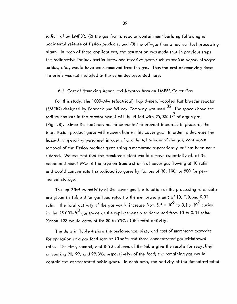
6.1 Cost of Removing Xenon and Krypton from an LMFBR Cover Gas
For this study, the 1000-Mw (electrical) Iiquid-metal-cooled fast breeder reactor
The space above the 32 (LMFBR) designed by Babcock and WiIcox Company was used.
sodium coolant in the reactor vesse! wi l l be f i l led with 25,000 ft of argon gas
(Fig. 18). Since the fuel rods are to be vented to prevent increases in pressure, the
inert fission product gases w i l l accumulate in this cover gas.
hazard to operating personnel in case of accidental release of the gas, continuous
removcd of the fission product gases using a membrane separations plant ha5 been con-
sidered. We assumed that the membrane plant would remove essentially a l l o f the
xenon and about 99% of the krypton from a stream o f cover gas flowing at 10 scfm
and would concentrate the radioactive gases by factors of 10, 100, or 500 for per-
3
Jn order to decrease the
manent storage.
The equilibrium activity of the cover gas is a function of the processing rate; datu
are given in Table 3 for gas feed rates (to the membrane plant) of 10, 1.0,and 0.01
scfm. The total activity of the gas would increase from 5.5 x 10
in the 25,000-ft gas space as the replacement rate decreased from 10 to 0.01 scfm.
Xenon-133 would account for 80 to 95% of the total activity.
6 7 to 3.1 x 10 curies
3
The data in Table 4 show the performance, size, and cost of membrane cascades
for operation at a gas feed rate o f 10 s c h and three concentrated gas withdrawal
rates. The first, second, and third columns of the table give the results for recycling
ar venting 90, 99, and 99.8%, respectively, of the feed; the remaining gas would
contain the concentrated noble gases. In each case, the activity o f the decontaminated

40
ORNL DWG 68-3577 R3 P = 1 atm; T = WOeF Vol. = 25,OM) ft3 Ar contoining Kr + Xe
COMPRESSOR AND COOLER
CASCADE INTERSTAGE FLOW
DECONTAMINATED ARGON H- TO STACK OR RECYCLE
-+ EXHAUST TO STACK 5000 liCi/sec TOTAL (Kr + Xe)
COVER GAS RECYCLE 50M) ilCi/sec TOTAL (Kr + Xe)
Fig. 18. Schematic Diagram for Removing Xenon and Krypton from the Argon Cover Gas of a 1000-Mw (electrical) Sodium-Cooled Fast Reactor.

Table 3. Calculated Concentrations of Noble Gases Above the Sodium Coolant i n the 1000-Mw (electrical) Reactor Designed by the Babcock and Wilcox Company
Blanket gas volume = 25,000 f t 3
Average Gas Feed Rate to Membrane Cascade (scfm) 10 1.0 0.01
3 Ci a toms/f t C i a tom s/f t 3 a toms/ft 3 C i
83rn Kr 85m Kr 85Kr 87Kr
B9Kr 131mxe 1 33m xe
88K,
’33xe
135Xe 1 3 7 ~ e 1 3 8 ~ e 41Ar
1 35rn xe
Total Ci
Kr Xe
9,800 39,800
43 70,000
108,000 9 , 660
16,300 89,400
4,470,000 62,200
356 , 000 33,900
258,000 2,200
237,303 5,285 , 800
0.140 x 0.134 x _ - 0.311 x 10’’ 0.681 x l O I 5 0 . 2 3 2 ~ 10l6 0 . 3 9 6 ~ 1013 0 . 3 6 0 ~ 1017 0 . 3 7 9 ~ 0 . 4 3 4 ~ 0 . 1 2 7 ~ 1015 0.251 x 0.182 x l O I 4 0 . 5 6 2 ~
10,600 46,500
41 8 73 , 600
’I 19,000 9,680
97,500 245,000
18,800,000 66,800
479,000 34,000
26 1,000 2,200
259 , 798 19,983,300
0.151 10’5
0.7’16~
0 . 1 5 7 ~ 0.302 x 1 O l 8
0 . 2 5 6 ~ 0.397 x 0 . 2 1 5 ~ 1018 0 . 1 0 4 ~ 1018 0 . 1 8 2 ~ IO2’
0 . 3 3 8 ~
0 . 5 6 8 ~ 1OI5
0 . 1 3 6 ~ 1015
0 . 1 8 2 ~ 1014
0.309 1014
0 . 1 5 3 ~ 10 15 10,700 47,300 0 . 1 6 0 ~ 4,310 0 . 3 1 2 ~
74,000 0.720 x 121,000 0.260 x
9,680 0.397 x 10¹³ 2 16,000 0.478 x 10¹⁸ - 30 2,000 0 . 1 2 8 ~
29,000,000 0.281 x lo2’ 66,900 0 . 1 3 7 ~
498,000 0.352 x
0.568 x 26 1 , 000 2,200 0.309 x
34,000 0 . 1 8 2 ~ 1014
266,990 30,377,900
5,523,103 20,243,098 30,644,890

42
Table 4. Performance, Size, and Cost of Several Cascades of Permselective Membranes for Separating Krypton and Xenon from the Cover Gas of a
Sodium -Cooled, 1000-Mw (e lec trical) Reactor
Gas feed rate to cascade = 10 scfin
Concentrated Gas Withdrawal Rate 1 scfm 0.1 scfm 0.02 scfm
Cascade Number of enriching stages Number o f strippin stages Membrane area, yd
Power requirement, kw Largest compressor, hp High-pressure side o f membrane,
Low-pressure side of membrane,
s Cascade volume, ft 3
psi
psi
Feed Gas K r concentration, at. YO Xe concentration, at. % Kr activity, Ci/ft3 Xe activity, Ci/ft 3
Recycle (or Vented) Gas Kr concentration, at. % Xe concentration, at. YO Kr + Xe activity, Ci/ft3 Kr + Xe activity, pCi/sec
Product Gas" Kr concentration, at. % Xe concentration, at. 70 Ar concentration, at. YO Kr activity, Ci/ft3 Xe activity, ci/ft3 Concentration factor, product/feed Number of storage cylinders per
week b
Installed cost, dollars
9 19 4630 - 9 1 26 9.2
150
0
0.004 0.1 36 24.4 542.6
0 . 4 7 ~ 10-5 o s x 10-9 0.029 4350
0.04 1.4 98.6 244 5426 10
50
289,000
15 20 23 24 5020 5 140 -10 -1 1 136 1 40 7.9 7.7
150 150
0 0
0.004 0.004 0.136 0.1 36 24.4 24.4 542.6 542.6
0.49 10-5 0.46 10-5 0.51 x 10⁻¹⁰ 0.030 0.0 28 4950 4657
0.25 x 10⁻¹⁰
0.4 2 14 68 85.0 30 2440 1 2,200 54,260 271,300 1 00 500
5 1
342,000 366,000
a b To be stored.
Standard N2 cylinders at a pressure of 2200 psi.

43
gas stream would be reduced to slightly less than 5000 pCi/sec, a level that i s
acceptable for discharge to the atmosphere at the present time. However, i t i s
l ikely that the decontaminated cover gas would be recycled to the reactor to elim-
inate the release of radioactive gases to the environment.
It i s significant to note that the concentrated product may be stored i n a very
small volume. The number of conventional gas cylinders (at 2200 psi) required per
week would be 50, 5, and 1, respectively, for the three product gas rates ( I , 6.1,
and 0.02 scfm) considered. The gas from one week's operation would produce about
3.2 x 10 w of heat. Blomeke and Perona, who have studied the cost of shipment
and storage of cy1 inders of concentrated radioactive noble gases, have concluded
that this method would be practical to at least the year 2000.
4 33
34 The costs of the various membrune plants do not differ widely. For example,
a plant for concentrating the original volume of gas by a factor of 10 would cost
$289,000, as compared with $366,000 for a plant providing a concentration factor
of 500. This i s due to the small equipment at the concentrating end of the cascade.
Our data on the effect of irradiation on membrane l i fe (Sect. 4.5) indicate that
the membrane in a plant such as that described in Table 4 would have only a very
short l i fe i f the cover gas from an LMFBR were fed directly to the separations plant.
Mast of the activiiy in the gas would be the result of short-lived isotopes of xenon
and krypton; consequently, the activity of the gas would decrease rapidly with time.
If the cover gas were retained for 20 days (either in a storage tank or on absorbents),
the l i fe of the membrane in the last concentrating stage o f the cascade would be
about 110 days, assuming that the membrane received a cumulative dose of 10 rads
prior to failure (Fig. 19). Retention of the cover gas for 30 days would increase the
membrane l i fe to about 6 years. Further economic studies wi l l be required before
the optimum balance between the cost of replacing membrane units and the cost of
retaining the cover gas can be determined. When this balance i s determined, the
total cost o f gas retention and the separations plant can be estimated.
8

44
0 R N L-DWG 70- I4505
C O V E R GAS R E T E N T I O N TIME (days)
Fig. 19. Variation of Membrane Life with Holdup Time o f Cover Gas from a 8 Sodium-Cooled Power Reactor. Basis: Irradiation of membrane to 10 rads.

45
6.2 Cost of Removing Noble Gases from a Reactor Containment Building
In order to estimate the costs of membrane plants for removing radioactive noble
gases following a nuclear accident, we selected a maximum credible loss-of-coolant
accident involving an advanced water-cooled reactor with the following characteristics: 35
Power, M w Thermal 3200 Electrical 1000
-2 -1 3 3 x 10 Flux, neutrons cm sec
Fuel loading Metric tons of uranium 100 Grams of uranium 1 08
Fuel enrichment 235u, %
mo I es a toms
2.3 1 0 4 6 x
6 Containment shell volume, ft 3 x 1 0
Time to accident (at end of fuel life) Days 6 25
Fuel irradiation, Mwd/metric ton 20,000
Seconds 5.4 x Id
Under these conditions, the concentrations of krypton and xenon in the containment
shell immediately after the accidental release would be about 100 and 650 ppm,
respectively. Since most o f the xenon and krypton would be nonradioactive, these
concentrations would not decrease appreciably with time. After a period of 1
day, the activity of the xenon would be about 150 times that of the krypton, and
the total activity in the containment shell would be more than 2 x 19 Ci (3.5 x 5 10 w). However, because of the relatively shorf half-life o f the xenon (the half-
l i fe o f the most abundant radioisotope, Xe, i s 5 days) and the long half-life of
much of the krypton (IO-year
after about 45 days, the Kr would become the limiting radioactive isotope. The
activity level (due to krypton) would remain at about the 10 -Ci level for several
8
133
85 Kr), the total activity would decrease rapidly until,
85
6
years. Analyses have shown that, because of the more rapid decay and more

46
effective removal of xenon, the decontamination o f the gas i s always limited by 35
the activity of the krypton i t contains.
A system for removing the noble gases from the reactor containment building has 36
been designed by Blumkin.
a membrane plant, effecting the removal o f a fraction of the noble gases on each
cycle. After 7 days, nearly a l l of the xenon and 99% of the krypton would be re-
moved, and the activity in the containment building would be reduced to a level
acceptable for discharges to the atmosphere. This process would require 27,840 yd
of membrane i n eight stages; the estimated capital cost is about $1,100,000. Later
considerations have indicated that there would be l i t t le incentive for removing the
noble gases from the reactor building so rapidly. A smaller plant that would remove
the noble gases within 35 days would have to be only one-fifth as large as the plant
just discussed and would cost about $300,000.
In this system, the gases are continuously cycled through
2
The exposure of the membrane in the last concentrating stage of a cascade for
removing noble gases from the reactor containment building was calculated a5 a
function of decay time before processing (Table 5). If the gases in the containment
shell were allowed to decay for 30 days and were subsequently removed by a membrane
plant during the next 7 days, the integrated exposure to the last stage would be about
1.2 x 10 rads. After a decay of 60 days, the exposure would be only about one-tenth
of this value. Since the radiation exposure i s nearly directly proportional to the
processing time, the exposure would be only about 6 x 10 rads i f a 35-day processing
period was used.
7
7
These calculations indicate that irradiation would not appreciably affect the
membrane during the removal of the noble gases from a reactor containment building
at the processing schedules considered. Considerably shorter decay times and longer
processing periods would be acceptable from the point of view o f the irradiation of
the membrane.

47
Table 5. Noble Gas Activity in the Shell, and Irradiation Exposurea of the Membrane i n the Last Concentrating Stage During Removal o f Noble Gases
from Nuclear Containment Shell
Basis: Size - 3200 Mw (thermal) FIUX - 3 x 10¹³ neutrons cm Fuel l i f e - 625 days Fuel load - 100 metric tons
Fuel irradiation - 20,000 Mwd ton
-2 -1 sec
Fuel enrichment - 2.3% 235 u
Containment volume - 3 x 10 L3 ft
Decay Time Before Processing 30 days 60 days 120 days -
5 Kr activity in shell, C i 9.0 x 10 8 . 9 5 ~ IO5 8 . 8 6 ~ 10
3
Init ial Kr dose rate to membrane, rads/min 2.78 x 10’ 2.78.x lo2 2.71 x 10
Xe activity i n shell, Ci 2.0x 10 8 . 0 ~ 10 1.ox 10
2
Init ial Xe dose rate to membrane, rads/min 9.72 x lo3 3.82 x 10’ 4.79 x 10”
2 2 Init ial total dose rate, rads/min 9 . 9 ~ ~ lo3 5 . ~ 9 ~ 10 2.71 IO
5 Integrated dose during a 7-day processing
period, rads 1.22 x IO7 1.07 x IO6 5.89 x 10
a Cafculated for the last stage of the cascade, where the noble gas concentration i s 100 times higher than the feed.

48
6.3 Cos t of a Permselective Membrane Plant for Processing Off-Gas from a Fuel Reprocessing Plant
In the aqueous processing of reactor fuels, the fuel i s usually dissolved in nitric
acid. Therefore, the dissolver off-gas contains nitrogen, oxygen, water vapor, nitrogen
oxides, xenon, and krypton. If the water vapor, nitrogen oxides, and other chemically
active gases were removed, the remaining gases could be treated i n a cascade of perm-
selective membrane stages to markedly reduce the concentration of radioactive noble
gases and thereby make discharge of the cleaned gas to the atmosphere practical.
The concentrated noble gases could be collected and stored indefinitely.
The curves in Fig. 20 show the relationship between cost and plant size as deter-
mined by the volume of dissolver off-gas to be treated per minute. These data were
calculated using the costs for the two applications reported above rather than from a
plant designed for this particular application. A 5-metric ton/day plant was assumed
to generate about 100 scfm of off-gas (see Table 6). Costs (Fig. 20) are given for
achieving off-gas decontamination factors (DF's) of 10, 100, and 1000; a l l values are
based on a concentration factor (CF) of 100 for the recovered noble gases. For com-
parison, the estimated costs for a plant for adsorbing noble gases in chlorofluoromethanes
are included.
allowances for building space or for head-end treatment facilities to remove nitrogen
oxides, water, etc.
37 These costs are for fully equipped, operable plants but do not include
Because of the delay between the discharge of fuel from the reactor and re-
processing, DF's greater than 100 are probably unnecessary, using present-day release
standards; for longer-cooled fuel (more than 60 days), DF's of 10 may be sufficient.
Under these conditions, the cost of a gas-separation system for a 5-metric ton/day
reprocessing plant i s in the range $280,000 to $420,000. A plant to reduce the level
of activity i n the off-gas by a factor of 1000 would cost abouf $420,000.
Calculations have been made of the irradiation exposure that would be received
by a membrane cascade used to remove the noble gases from the off-gas from a LMFBR
fuel reprocessing plant. Exposures received during the processing of 30-day-cooled

49
~
CONCENTRATION FACrOR (CF) DECONTAMINATION FACTOR (DF)
ADSORPTION PLANT - 2 - - 3 - - 4 - CF = 1400 CF = 314 CF = 62 DF = > 103 DF 7 30 DF - 100
MEMERANE - .............. PLANT - CF = 100
ORNL DIVG. 69.1156
GAS PROCESSING RATE (scfm)
Fig. 20. Estimated Capital Costs for Removing Noble Gases from Off-Gas of a 5-metric ton/day Reactor Fuel Processing Plant.

50
Table 6. Noble Gas Activity in the Off-Gas from a Fuel Reprocessing Plant,38 and Exposure of the Membrane
Basis: Reactor Fuel Processing Plant LMFBR (Atomics International
Burnup - 80,000 Mwd/metric ton irradiation time - 540 days Composition - mixed core and
Rate - 5 metric tons of fuel per day Decay time - 30 days Off-gas flow - 100 +/,in oxide reactora)
blanket
Reactor Fuel 30-day -coo I ed 60-day-cooled
2.383 x
3.134 x
3.503 x
3.742 x
4
4
4
5
85Kr, Ci/ton fuel 3.395 x 10
1.477 x 10
2.958 x 10
Xe, Ci/ton fuel 1 . 9 3 5 ~ 10
731m Xe, Ci/ton fuel
133m~e, Ci/ton fuel
133
Off-gas, scfm 7 00 100
Concentration facto-r, top stage 7 00 7 00
Concentration factor, second stage 43.5 43.5
o4
o3
o - ~
o3
5
5
5.74 x 10
2.50 x 10
6
6
Membrane exposure, top stage, rads/day 3.99 x 10
1.74 x 10 Membrane exposure, second stage, rads/day

51
fuel would be the most stringent requirements expected for a fuel reprocessing plant
i n the near future. Under the proposed operating conditions, i f the membrane were 8 2 replaced after receiving a radiation dose of 1 x 10 rads, the 7 yd of membrane in
the last concentrating stage would need to be replaced about every 58 days; other
stages would need to be replaced at longer intervals. About 50 years would be
required to give the membrane at the feed stage an equivalent exposure. Only the
last five stages would be needed to be replaced, due to irradiation exposure, at
intervals of less than two years. The total membrane replaced in these stages over
a period of two years would be about 630 yd and would cost about $3150 per year.
If the only cause of failure was irradiation, the prorated cost o f replacing the rnem-
brane in the feed stage plus al l concentrating stages would be about $10,000 annually.
2
If the fuel were allowed to decay for 60 days prior to processing, the irradiation
exposures would be only about one-seventh o f those encountered with 30-day-cooled
fuel. In this case, the replacement cycle for the top stage of the concentrating
section would be longer than one year.
7. REFERENCES
1.
2.
3.
4..
5.
C. M. Slansky, H. K. Peterson, and V. G. Johnson, "Nuclear Power Growth Spurs
Interest i n Fuel Plant Wastes," Environ. Sci. Technol. - 3(5), 446-51 (1969).
J. J. de Nunno, F. D. Anderson, R. E. Baker, and R. L. Waterfield, Calculation
of Distance Factors for Power and Test Reactor Site, TID-14844 (Mar. 23, 1962).
G. W. Keilholtz, "Removal of Noble Gases from Off-Gas Streams," Nucl. Safety
- 8(2), 155-60 (1966).
J. B. Robertson, Behavior of Xenon-133 Gas After Injection Underground,
IDO-2205 1, U. S. Geological Survey, Waste Resources Division, Idaho Fa1 Is, Idaho (July 1969).
L. A. WeIler, The Adsorption of Krypton and Xenon on Activated Carbon - A Bibliography, MLM-1092, Mound Laboratory, Miamisburg, Ohio (1959).

52
6.
7.
8.
9.
10.
11.
12.
13.
14.
C. M. Slansky, H. K. Peterson, and V. G. Johnson, "The Production and Waste
Management of Krypton-85 in Nuclear Power Industry in 1970 - 2000 A.D.,"
Idaho Nuclear Corporation (to be published).
J. R. Merriman e t al., "Concentration and Collection of Krypton and Xenon by
Selective Adsorption in Fluorocarbon Solvents" (SM-1?0/25), p. 303 in the
Proceedings of the Symposium on Operating and Developmental Experience in
the Treatment of Airborne Radioactive Wastes, International Atomic Energy
-
Agency, August 1968.
R. F. Toylor and 6. P. Wall, "Development of a Production Process for Radio-
Krypton Recovery by Fractional Absorption," Progr. Nucl. Energy, Ser. I V - 5,
307-45 ( 1963).
Vijay Mohan Bhatnagar, Clathrate Compounds, pp. 103-107, S. Chand and Co.,
Delhi, India, 1968.
J. Slivnik, "Recovery of Xenon and Krypton in the Treatment of Gaseous Radio-
active Wastes I' (SM-l10/24), p. 315 in Proceedings of the Symposium on Operating
and Developmental Experience in the Treatment o f Airborne Radioactive Wastes,
International Atomic Energy Agency, August 1968.
R. H. Rainey, W. L. Carter, S. Blumkin, and D. E. Fain, "Separation of Radioactive
Xenon and Krypton from Other Gases by Use of Permselective Membranes"
(SM-110/27), p. 323 in the Proceedings o f the Symposium on Operating and
Developmental Experience in the Treatment of Airborne Radioactive Wastes,
International Atomic Energy Agency, August 1968.
J. K. Mitchell, "On the Penetrativeness of Fluids," J. Roy. Inst. - 2, 101-8,
307-21 (1831).
J. K. Mitchell, "On the Penetration of Gases," Am. J. Med. Sciences - XIII,
100-1 12 (1833).
Proceedings of Symposium, Membrane Processes for industry, Birmingham, Ala.
May 19-20, 1966.

53
15.
16.
17.
18.
19.
20.
21.
22.
23.
24.
25.
26 e
R. W. Roberts, The Effect of Polymeric Structure Upon Gas Petmeation, Ph.D.
Thesis 62-2410, State University of Iowa (1962).
S. A. Stern, 'I Industrial Application of Membrane Processes: The Separation of
Gas Mixtures, 'I Proceedings of Symposium, Membrane Processes for industry,
Birmingham, Ala., May 19-20, 1966.
N. Lakshrninarayanaiah, "Transport Phenomena in Art i f ic ial Membranes," Chem.
Rev. 65(5), (1965). - Karl Kammermeyer, "Silicone Rubber as a Selective Barrier," Ind. Eng. Chem.
49('10), 1685-86 (1957). - R. M. Burrer and H. T. Chio, "Solution and Diffusion of Gases and Vapors in
Silicone Rubber Membranes," J. Polymer Sci., Pt. C, No. 10, 11 1-38 (1965).
C. J. Major, "Investigation of Unique Gas Permeability Cell System to Remove
CO
Chemical Engineering, University of Iowa, for National Aeronautics and Space
Administration (1 965).
and Other Noxious Gases from Space Cabins," N 65-29624, Department of 2
W. L. Robb, Thin Silicone Membranes and Their Permselective Properties and
Some Applications, Report 65-@-031, General Electric Company (1965).
J. M. Holmes, private communication to D. E. Fergwson (October 1965).
R. N. Ricles, "Molecular Transport i n Membranes," Ind. Eng. Chem. I_ 58(6),
19-35 (1 966).
Samuel Blumkin, A Method for Calculating Gradients for Mu1 ticomponent Systems
Involving Large Separation Factors, K-OA-1559 (1968).
5. H. Jury, Analysis of Fractionation of Gas Mixtures Using Dimethyl Silicone
- Rubber Membranes (to be published).
S. A. Stern and W. P. Walawender, "Analysis of Membrane Separation Parameters,"
Separation Sci. 4(2), - 129-59 (1969).

54
27.
28.
29.
30.
31.
32.
33.
34.
35.
36.
37.
H. P. Ekiggs, General Electric Company, personal communication.
R. M. Barrer, "Diffusion in Elastomers," Kolloid-Z. - 120(1), 177-86 (1951).
A. Charlesby, Atomic Radiation and Polymers, pp. 297-31 1, Pergamon, New York,
1960.
A. E. Chapiro, Radiation Chemistry of Polymeric Systems, lnterscience, New York,
1962.
J. W. Boon, "Elastomeric Material," pp. 245-88 in Radiation Effects on Organic
Materials, ed. by R. 0. Bolt and J. G. Carroll, Academic, New York, 1963.
Babcock and Wilcox Company, 1OOO-MWe W F B R Follow-on Study - Task I1 and
1 1 1 Final Report, Vol. 1-5, 13AW-1328 (February 1969).
J. 0. Blomeke and J. J. Perona, Management of Noble Gas Fission Product
Wastes from Reprocessing Spent Fuels, ORNL-TM-2677 (Nov. 22, 1969).
S. Blumkin, Permselective Membrane Cascades for the Separation o f Xenon and
Krypton from Argon, K-OA-1622, Rev. 1 (1968).
R. H. Rainey, Criteria for Noble-Gas Removal Using Permselective Membranes,
0 RN L-TM- 1822 (1 967).
S. Blumkin to D. M. Lang, Separation of Krypton from Air by Means of a
Permselective Membrane, K-OA-1552, Rev. 1 (Nov. 28, 1967).
J. R. Merriman and J. H. Pashley, Engineering Development of an Adsorption
Process for the Concentration and Collection of Krypton and Xenon: Fourth
Summary Progress Report, July through December, 1968, K-1786 (April I, 1970).
K. Buttrey, 0. R. Hilling, P. M. Mager, and E. H. Ottewitte, "LMFBR Task Force
Fuel Study," NAA-SR-Memo 12604 (Jan. 10, 1968).
38.

55
ORNL-45 2 2 U C - 1 0 - Chemi-ea1 Sepa ra t ions Processes
f o r Plutonium and Uranium
INTERNAL UISTRT BUTLON
1. Biology L i b r a r y
5. ORNL - Y-12 Techn ica l L i b r a r y Document Reference S e c t i o n
6- 22 ~ Labora tory Records Department 23. Labora tory Records, ORNL R . C . 2 4 . E. S. B e t t i s
25-34. R. E . Blanco 35. J . 0. Blorurke 36. W. J . Boegly, Jr .
37-40. S . Blumkin (K-25) 41. R . E . Brooksbank 4 2 . W . H. Br idges 43. F . N . Rrowdtlr 44. I(. B. Brown 45. W. E. Browning 46. .J. R. Buchanan 47. W. L. Carter 48. W. B . C o t t r e l l 49. I;. h. Cowser 50. D . J . Crousc 51. F. I,. C u l l e r 52. J . T . Day 53. I>. E. Fain (K-25) 54. D. E. Ferguson 55. L . M. F e r r i s 56. J . H. Gibbons 57. K. W. Glass 58. J . M. Googin (Y-12) 59. J - M. Holmes 60. A. R. I rv ine
2-4. C e n t r a l Research L i b r a r y 61. 62. 63. 64. 65. 66. 67. 6s. 69. 70. 71.
72-76. 77. 7 8 . 79. 80. 81. 82. 83. 84. 85, 86. 8 7 . 88. 89. 90. 91. 92. 93. 94.
I). G . Jacobs R. J . Ked1 G . W. K e i l h o l t z U. M. Lang (Y-1.2) S . A. Lev1.n (Y-12) H. G. MacPherson W . C . McClairi J . R. Merriman (K-2.5) J. E'. Nichols J. H. Pash ley (K-25) J . J . Perona K. H. Rainey M. W. Rosentha l Jerome Roth Dunlap S c o t t , Jr . M. J . Skinner A . N . Smith E. G . S t ruxness 1)- A. Sundberg D. B. Trauger W. E. Unger E . Von Ba1l.e (K-25) A . M . Weinberg M. E , Whatley R. G. Wymer P . H. E m m e t t (consultant) J . J . Katz ( c o n s u l t a n t ) J . L . Margrave. ( c o n s u l t a n t ) E . A . Mason ( c o n s u l t a n t ) R. B , R ichards ( c o n s u l t a n t )
EXTERNAL DISTRIBUTION
AEC, Idaho Opera t ions O f f i c e , P.O. Box 2108, ldaho F a l l s , Tdaho 83401
AEC, Oak Ridge Opera t ions , Oak Kidge, Tennessee 37830
95. K. K. Kennedy
96. C . S . Shoup 97. Labora tory and U n i v e r s i t y Div i s ion 98. P a t e n t Office
AEC, Oak Ridge Opera t ions , S i t e R e p r e s e n t a t i v e , ORNL 99. H. W. Behrman

56
AEC, Washington, D.C. 20545 100. C . B. Bar t le t t 101. W. G . Belter 102. D. J . Donoghue 103. W. H. McVey 104. H. A. Nowak 105. A. F. Perge 106. A. J . Pressesky 107. W. H. Regan 108. H. Schneider
A l l i e d Chemical Nuclear Products , I n c . , P.O. Box 35, Florham Park, N . J . 07932 109. R . I. Newman 110. A. Schneider 111. E . M. Shank
Argonne Na t iona l Labora tory , 9700 South Cass Ave., Argonne, Ill . 60440 1 1 2 . R. C . Vogel 113. D. S. Webster
B a t t e l l e Memorial I n s t i t u t e , P a c i f i c Northwest Labora tory , FFTF Dr ive ,
114. C. J . Foley
Babcock and Wilcox Co., Atomic Energy Div i s ion , P.O. Box 1260, Lynchburg,
115. Harry Honig
C V I Corpora t ion , Box 2138, Columbus, Ohio 43216 116 . Harold P a r i s h
E . I. Du Pont d e Nemours and Co., Savannah River P l a n t , Aiken, S.C. 29801 117. L. H. Meyer 118. C. H. Ice 119. C . M. P a t t e r s o n 120. E. B. Sheldon 121.. Harold Hu l l
Dow Chemical Company, Rocky F l a t s D i v i s i o n , P.O. Box 888, Golden, Colorado 80401
1 2 2 . D. L. Z i e g l e r
Environmental Heal th Research and T r a i n i n g Center , Room 1108, Mayo Bu i ld ing ,
123. C . P . S t r aub
General Electr ic Company, 175 Cur tne r , Ave., San J o s e , C a l i f o r n i a 95125 124. R. G . Barnes
General Electr ic Company, V a l l e c i t o s Labora tory , P l easan ton , C a l i f . 94566 125. W. H. R e a s
General E l e c t r i c Company, Nuclear Energy Div i s ion , 310 D e Guigne Dr ive ,
126. G. D. Hoggatt
P.O. Box 999, Richland, Washington 99352
V i r g i n i a 24505
School of P u b l i c Heal th , Un ive r s i ty of Minnesota, Minneapol is , Minn. 55455
Sunnyvale, C a l i f o r n i a 94086

57
General Electric Company, Medical Development Operations, Bldg. 5 ,
127. J. J . Kasglaw 128. W. J. Ward I11
Environmental Technology, Inc., Schenectady, N.Y. 12300 129. Angelo Dounancas
Gulf Energy and Environmental Systems, Tnc., Box 608, San Diego,
130. L. H. Brooks
General Electric Company, Midwest Fuel Recovery Plant, Route 1, Box
131 . K. W. Lambert
Idaho Nuclear Corporation, ldaho Falls, Tdaho 83401 132. J. A. Buckham
Idaho Nuclear Corporation, Nuclear Keactor Testing Station, Idaho F a l l s , Idaho 83401
133. G. I?. Offutt
Johns Hopkins University, 513 Ames Hall, Baltimore, Maryland 21218 134. Abel Wolman
Los Alamos Scientific Laboratory, P.O. Box 1663, Los Alamos, N.M. 87544 135. C. W . Christenson
Mound Laboratory, Bldg. A , Room 155 , Miamisburg, Ohio 45342 136. S. Freeman
Nuclear Fuel Services, Znc., Wheaton Plaza Bldg., Wheaton, Md. 20902 1 3 7 . W. H. Lewis
Nuclear Fuel Services, Inc., P.0 , Box 124 , West Valley, N.Y. 14171 138. R. T . Smokawski
Iowa Electric Light and Power Co., Cedar Rapids, Iowa 52420 139. Dave Flanagan
WADCO, Inc., P.O. Box 1970, Richland, Washington 99352 140. C. R. Cooley
Syracuse University, Syracuse, N.Y. 13210 141. S. A . Stern
University of California, Berkeley, California 94700 142. W. J . Kaufnian
University of North Carolina, Chapel Hill, N.C. 27514 143. H. C. Thomas
University of Texas, Austin, Texas 78712 144. E. R. Gloyna
Vanderbilt University, Nashville, Tennessee 37203 145. F. L. Parker
Schenectady, N.Y. 12300
California 92100
219B, Morris, Ill. 60450

WRSPO, Atomic Energy Division, Phillips Petroleum Company, Idaho F a l l s , Idaho 83401
146. W. L. Slagle 1 4 7 . G. 0. Bright
Atlantic Richfield Hanford Co., Attn: Document Control, P.O. Box 250,
148. R. E. Tomlinson
Nuclear Institute "Joze f Stefan, 1, j ubl j ana, Yugoslavia 149. J. Slivnik
Union Carbide Corporation, New York, New York 10017 150. J. A . Swartout
151-286. Given distribution as shown in TID-4500 under Chemical Separations
Richland, Washington 99352
Processes for Plutonium and Uranium category (25 copies - NTIS)


