Department of Electron Devices, Materials, and Electromagnetic Radiation, Faculty of Engineering, Tel-Aviv University, Tel-Aviv, Israel,69978
Received February 26, 1990; accepted August 6, 1990
The joint-transform correlator operation has been extended to include complex reference images. Such amplitudeand phase images are common when single harmonic images (circular, radial, logarithmic, etc.) are used incorrelation setups. The analysis of a rotation-invariant pattern-recognition system using joint-transform correla-tor principles is described, followed by experimental results that can be obtained in real time.
The optical joint-transform correlator (JTC) was firstproposed by Weaver and Goodman.' The scheme isbased on recording the Fourier transform that is si-multaneously displayed by a pair of two-dimensionalfunctions and then generating the transform of thispattern. The correlation of the two functions is thusobtained without using a conventional matched spa-tial filter and its required sensitive alignment care.Yu and Liu2 applied this technique to real-time pat-tern-recognition configurations by using spatial lightmodulators in the optical system. The JTC preservesthe shift-invariant pattern-recognition property buthas a high sensitivity to other invariant parameters,such as rotation, scale, and projection. One way ofadding one of these invariances is by using multiplereference objects in the input plane of the JTC assuggested by Javidi and Odeh.3 However, this per-mits only a limited amount of invariance to beachieved, since one can use only a few different angu-lar orientations of the same object at the input plane.This concept works well in computer simulations, butthe real-time optical results are disappointing, espe-cially when we try to increase the number of referenceobjects.
It has recently been shown-6 that the classical cor-relator configuration can be made invariant to oneadditional parameter by using a matched filter con-taining only a part of the input data. This addedparameter could be the angular orientation of an ob-ject, when the correlation is performed with respect toonly one harmonic out of the circular harmonic de-composition,4 or the scale of the object, when thematched filter consists of one harmonic out of theradial harmonic decomposition.5'6 Recently we de-scribed two other types of harmonic decomposition,the logarithmic harmonic, which permits projection(i.e., aspect ratio) invariant pattern recognition, andthe more general deformation harmonic,8 which canhandle any type of distortion parameters (includingthe parameters mentioned above).
We demonstrate in this Letter a complex reference-invariant JTC by using a single harmonic of the storedpattern as the reference object. In general, a harmon-ic has phase as well as amplitude information, andthus one cannot use a simple transparency at the inputplane.9 The complete information contained in a har-monic would thus require two masks, a kinoform for
the phase data and a transparency for the amplitudedistribution. To our knowledge this is the first timethat such complex images are handled in JTC setups.
Yu et al.9 have shown that by using the real andimaginary parts of a circular harmonic function as twoseparate positive reference objects in a JTC setup,rotation and shift-invariant pattern recognition can beachieved. This approach is based on a digital post-processing step that performs the addition of the twocorrelation peaks, one from the real part of the circularharmonic and the other from the imaginary part.Moreover, this scheme permits the determination ofthe exact angular orientation of the input by evaluat-ing the ratio of the two correlations.
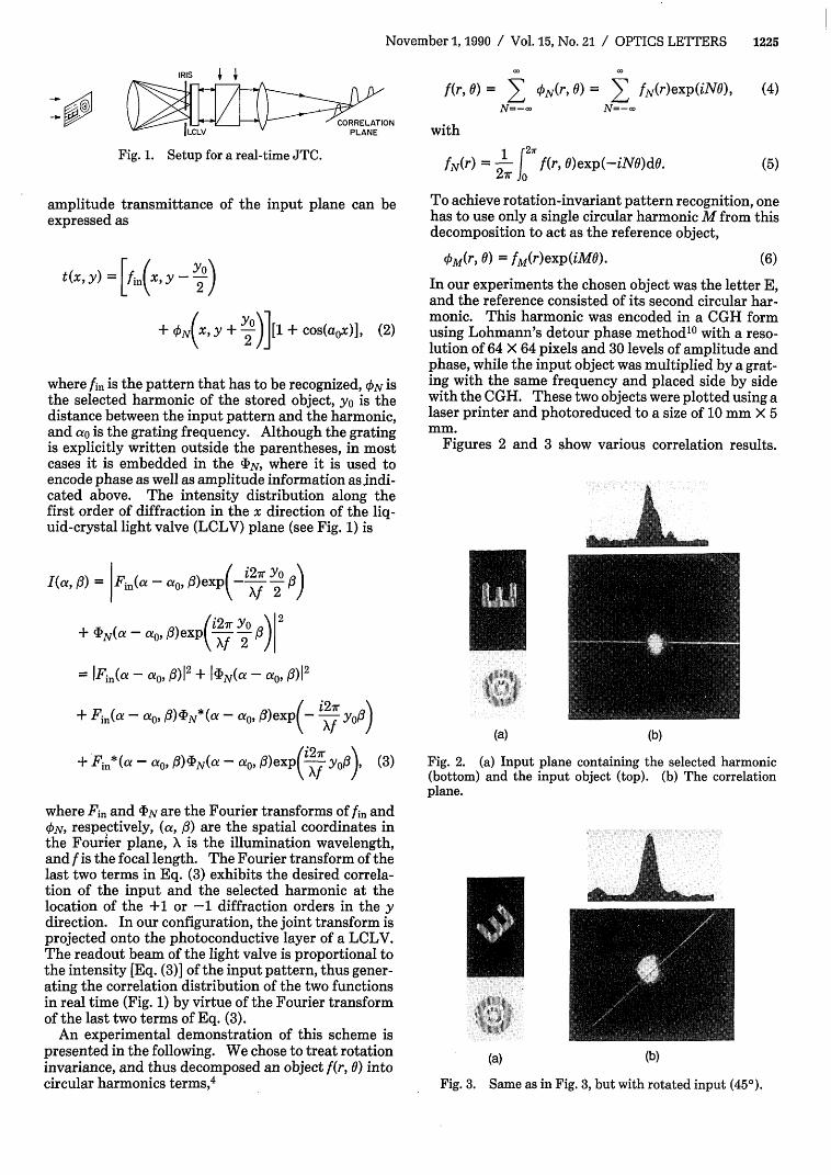
To eliminate the use of an electronic processingstep, we preferred a different approach, based on en-coding phase and amplitude harmonic informationthrough a computer-generated hologram (CGH) usingLohmann's detour phase approach.10 One shouldnote that here we encode the harmonic itself and notits spectra, as in the more conventional CGH's that actas matched filters. The CGH that carries the har-monic has to be placed side by side with the inputpattern in a common input plane. The basic nature ofthe CGH is that it displays the information along oneof the diffraction orders in an off-axis direction, andthus the input pattern has to be modulated also by thesame grating. The two diffracted beams now propa-gate along parallel paths and thus will manifest thejoint-transform correlation along this direction. Thesimplest way to achieve the input pattern modulationwould be to place an amplitude grating in the inputlocation onto which the input itself will be placed orprojected. The experimental setup that is capable ofperforming this operation in real time is shown in Fig.1.
Assume that the stored pattern f(x, y) is decom-posed into a set of arbitrary harmonics ckN(X, y),
f(x,y) = E ON(X, Y)-N=-X
(1)
The input plane now contains the input pattern multi-plied by a uniform grating and, along one of its sides, aspecific CGH encoding one harmonic. As a result, the
amplitude transmittance of the input plane can beexpressed as
f(r, 0) = E kN(r, 0) = E fN(r)exp(iN0),~~1N-N=-w N=-i
with
fN(r) = 12 f(r, 0)exp(-iNO)dO.
(4)
(5)
To achieve rotation-invariant pattern recognition, onehas to use only a single circular harmonic M from thisdecomposition to act as the reference object,
tkM(r, 0) = fM(r)exp(iMO). (6)
t(x, y) = n 2 )
+'ON , Y + 2°)[1 + cos(aox)],(2)
where fin is the pattern that has to be recognized, ON isthe selected harmonic of the stored object, yo is thedistance between the input pattern and the harmonic,and ao is the grating frequency. Although the gratingis explicitly written outside the parentheses, in mostcases it is embedded in the IN, where it is used toencode phase as well as amplitude information as.indi-cated above. The intensity distribution along thefirst order of diffraction in the x direction of the liq-uid-crystal light valve (LCLV) plane (see Fig. 1) is
I(a, A) = |Fin(a- o, ( -i2Xr Yo
/i27rYo 2+ (DN(a -a 0), 03exp ~ -- f 2\ XJ 2 /|
= IFWin(a -o, 3 12 +I 4N(a - a,, 0)12
+ Fin(a ao, 0)4,N*(a -ao, )exp (- i2-z YrXf /
+ Fin*(a - a,0' /I)N(a - a0 , f)exp( irf Yo ) (3)
where Fin and (bN are the Fourier transforms of fin andON, respectively, (a, A) are the spatial coordinates inthe Fourier plane, X is the illumination wavelength,and f is the focal length. The Fourier transform of thelast two terms in Eq. (3) exhibits the desired correla-tion of the input and the selected harmonic at thelocation of the +1 or -1 diffraction orders in the ydirection. In our configuration, the joint transform isprojected onto the photoconductive layer of a LCLV.The readout beam of the light valve is proportional tothe intensity [Eq. (3)] of the input pattern, thus gener-ating the correlation distribution of the two functionsin real time (Fig. 1) by virtue of the Fourier transformof the last two terms of Eq. (3).
An experimental demonstration of this scheme ispresented in the following. We chose to treat rotationinvariance, and thus decomposed an object f(r, 0) intocircular harmonics terms,4
In our experiments the chosen object was the letter E,and the reference consisted of its second circular har-monic. This harmonic was encoded in a CGH formusing Lohmann's detour phase method10 with a reso-lution of 64 X 64 pixels and 30 levels of amplitude andphase, while the input object was multiplied by a grat-ing with the same frequency and placed side by sidewith the CGH. These two objects were plotted using alaser printer and photoreduced to a size of 10 mm X 5mm.
Figures 2 and 3 show various correlation results.
IIFl(a) (b)
Fig. 2. (a) Input plane containing the selected harmonic(bottom) and the input object (top). (b) The correlationplane.
(a) (b)
Fig. 3. Same as in Fig. 3, but with rotated input (450).
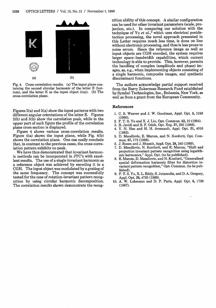
Fig. 4. Cross-correlation results. (a) The input plane con-taining the second circular harmonic of the letter E (bot-tom), and the letter K as the input object (top). (b) Thecross-correlation plane.
Figures 2(a) and 3(a) show the input patterns with twodifferent angular orientations of the letter E. Figures2(b) and 3(b) show the correlation peak, while in theupper part of each figure the profile of the correlationplane cross section is displayed.
Figure 4 shows various cross-correlation results.Figure 4(a) shows the input plane, while Fig. 4(b)shows the correlation plane. One can easily concludethat, in contrast to the previous cases, the cross-corre-lation pattern exhibits no peak.
We have thus demonstrated that invariant harmon-ic methods can be incorporated in JTC's with excel-lent results. The use of a single invariant harmonic asa reference object was achieved by encoding it in aCGH. The input object was modulated by a grating ofthe same frequency. The concept was successfullytested for the case of rotation-invariant pattern recog-nition by using circular harmonic decomposition.The correlation results shown demonstrate the recog-
nition ability of this concept. A similar configurationcan be used for other invariant parameters (scale, pro-jection, etc.). In comparing our solution with thetechnique of Yu et al.,9 which uses electrical postde-tection processing, the novel approach presented inthis Letter requires much less time, is done on linewithout electronic processing, and thus is less prone tonoise errors. Since the reference image as well asinput objects are CGH encoded, the system requireslarger space-bandwidth capabilities, which currenttechnology is able to provide. This, however, permitsthe handling of complex (amplitude and phase) im-ages, as, e.g., when implementing objects consisting ofa single harmonic, composite images, and syntheticdiscriminant functions.
The authors acknowledge partial support receivedfrom the Barry Zukerman Research Fund establishedby Symbol Technologies, Inc., Bohemia, New York, aswell as from a grant from the European Community.
References
1. C. S. Weaver and J. W. Goodman, Appl. Opt. 5, 1248(1966).
2. F. T. S. Yu and X. J. Liu, Opt. Commun. 52, 10 (1984).3. B. Javidi and B. F. Odeh, Opt. Eng. 27, 295 (1988).4. Y. N. Hsu and H. H. Arsenault, Appl. Opt. 21, 4016
(1982).5. D. Mendlovic, E. Marom, and N. Konforti, Opt. Com-
mun. 67, 172 (1988).6. J. Rosen and J. Shamir, Appl. Opt. 28, 240 (1989).7. D. Mendlovic, N. Konforti, and E. Marom, "Shift and
projection invariant pattern recognition using logarith-mic harmonics," Appl. Opt. (to be published).
8. E. Marom, D. Mendlovic, and N. Konforti, "Generalizedspatial deformation harmonic filter for distortion in-variant pattern recognition," Opt. Commun. (to be pub-lished).
9. F. T. S. Yu, X. L. Eddy, S. Jutamulia, and D. A. Gregory,Appl. Opt. 28,4725 (1989).
10. A. W. Lohmann and D. P. Paris, Appl. Opt. 6, 1739(1967).