21
Complex Static Stresses and Torsion UAA School of Engineering CE 334 - Properties of Materials Lecture # 17 1
| Date post: | 18-Dec-2015 |
| Category: |
Documents |
| View: | 217 times |
| Download: | 0 times |

Complex Static Stresses and Torsion
UAA School of Engineering
CE 334 - Properties of Materials
Lecture # 17
1

Quiz 1: The State of Stress
ABCDE
Stresses at point A:
Stresses at point B:
Stresses at point C:
Stresses at point D:
Stresses at point E:
P
1

Quiz 2: Stresses Acting on Other Directions
600 psi
250 psi
600 psi
250 psi
=?
=?
Welding Plan =37o
3

Complex Static Stresses
• Complex Stress States:
and in three directions
• Typical complex stress states: Biaxial stresses are stresses applied
along two axes of the element and = 0.Triaxial stresses are stresses applied along
three axes of the element and = 0.
4
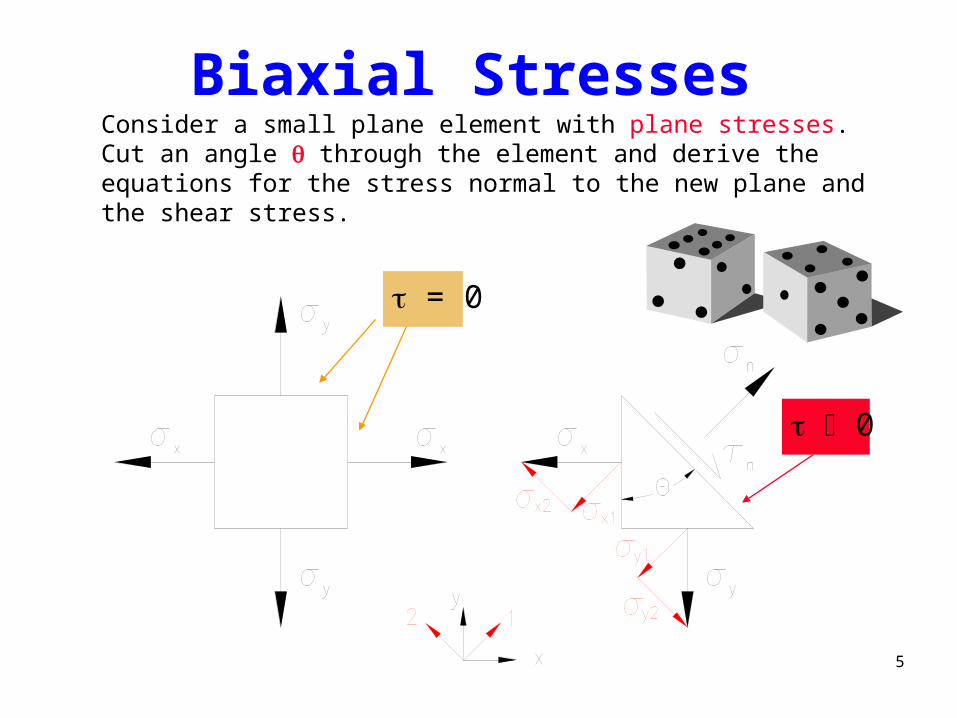
Biaxial StressesConsider a small plane element with plane stresses. Cut an angle through the element and derive the equations for the stress normal to the new plane and the shear stress.
= 0
0
5

Stress Normal to Plane
2cos22
sincos
sin)sin(cos)cos(
)sin()cos()(0
22
111
yxyxn
yxn
yxn
nynxnn dAdAdAF
6

Shear Stress on Plane
F dA dA dAn n x n y n
n x y
n x y
n
x y
2 2 20
22
( ) ( cos ) ( sin )
( sin ) cos ( cos ) sin
( ) sin cos
sin
Note that the maximum shear stress occurs when the angle equals 45 degrees.
7
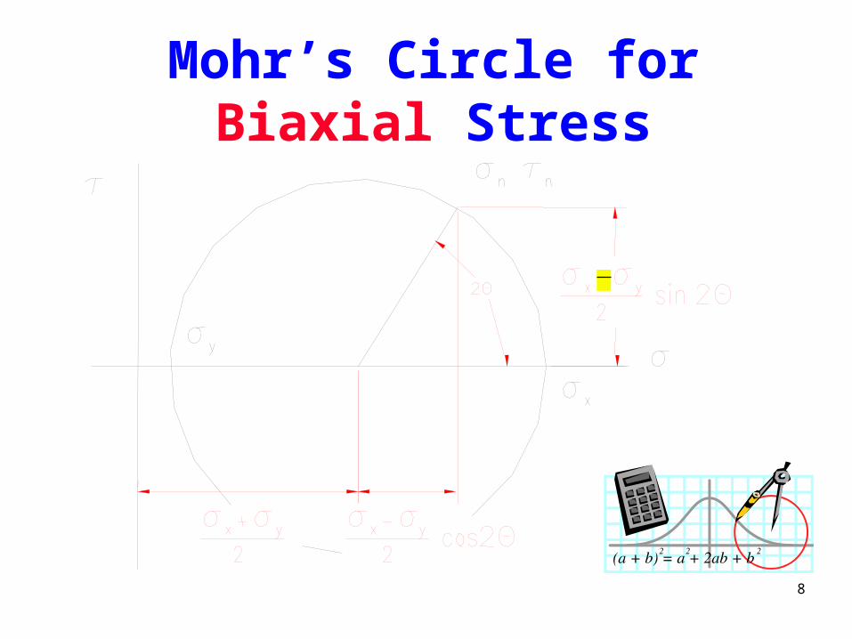
Mohr’s Circle for Biaxial Stress
8

Triaxial Stress• Normal stresses are in three dimensions.• Shear stress in each of these three dimensions is zero. • The following element is in triaxial stress state.
9
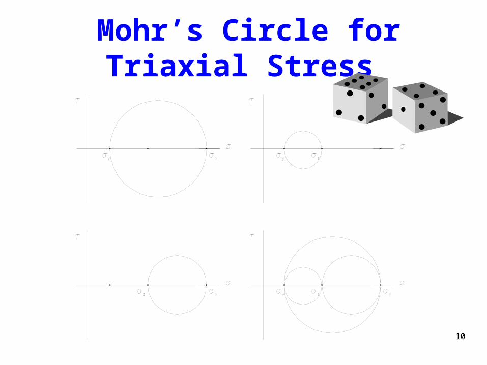
Mohr’s Circle for Triaxial Stress
10

Triaxial Strain• Stresses usually act in all three directions • It is necessary to modify Hooke’s Law regarding stress and strain
in the elastic range in order to include Poisson’s effects in each direction, caused by the strains in the other two directions.
• The generalized equations for Hooke’s Law are given below:
1 1 2 3
2 2 3 1
3 3 1 2
1
1
1
E
E
E 11

Purposes of Torsional Tests
The purposes of torsion tests usually parallel those for tension tests:
– Determine the proportional limit and the ultimate strength in shear
– Determine the modulus of rigidity (G)– Plot stress-strain curve for material
behavior in shear
12
Torsion Procedure and Set up
• Torsion specimens: round bars
• Torsion apparatus: similar to tension
• The ends of a specimen should be securely gripped
• Apply torque
• Measure the torque and the angle of twist
13
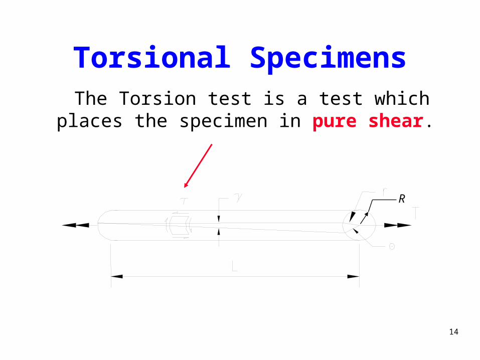
Torsional Specimens The Torsion test is a test which places the
specimen in pure shear.
R
14

Torsional Quantities
Shear Strain:
Shear Stress:
L
r
J
Tr
R
15
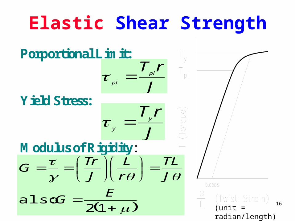
Elastic Shear Strength
Porportional Limit:
Yield Stress:
Modulus of Rigidity:
J
rTpl
pl
J
rTy
y
12 :also
EG
J
TL
r
L
J
TrG
(unit = radian/length)16

Torsional Modulus of Resilience
GR
r
rR
Lrr
L
r
JR
TR
R
pl
pl
plpl
pl
plpl
4
42
2
1
volume2
Treach tovolumework/unit
2
2
4
4
21
2
pl
(unit = radian/length)
)( radiusr
17

Torsional Plastic Strength
• Yielding begins at outer surface.
• Stress variation is no longer linear.
• Yielding continues until the cross section is fully yielded.
18

Torsional Plastic Shear Strength
Modulus of Rupture:
Ductility:
Modulus of Toughness:
J
RTuu
% L
100
T T
ALu pl f
2
u
19

Torsional Fracture
• Ductile materials fracture in shear.
• Brittle materials fracture in tension.20
Review Mechanics
21


