24
| Date post: | 13-Jul-2015 |
| Category: |
Education |
| Upload: | alessandro-palmeri |
| View: | 3,497 times |
| Download: | 1 times |

Teaching schedule Week Lecture 1 Staff Lecture 2 Staff Tutorial Staff 1 Beam Shear Stresses 1 A P Beam Shear Stresses 2 A P --- --- 2 Shear centres A P Basic Concepts J E-R Shear Centre A P 3 Principle of Virtual
forces J E-R Indeterminate Structures J E-R Virtual Forces J E-R
4 The Compatibility Method
J E-R Examples J E-R Virtual Forces J E-R
5 Examples J E-R Moment Distribution -Basics
J E-R Comp. Method J E-R
6 The Hardy Cross Method
J E-R Fixed End Moments J E-R Comp. Method J E-R
7 Examples J E-R Non Sway Frames J E-R Mom. Dist J E-R 8 Column Stability 1 A P Sway Frames J E-R Mom. Dist J E-R 9 Column Stability 2 A P Unsymmetric Bending 1 A P Colum Stability A P 10 Unsymmetric Bending 2 A P Complex Stress/Strain A P Unsymmetric
Bending A P
11 Complex Stress/Strain A P Complex Stress/Strain A P Complex Stress/Strain
A P
Christmas Holiday
12 Revision 13 14 Exams 15 2
MoAvaAons (1/3)
• Similarly to the stresses:
– Normal strain εn and shear strain γmn change their values with the orthogonal direcAons m and n being considered
– A Mohr’s circle can be used to represent and analyse the variaAons of εn and γmn, and therefore: • Find the principal stresses εp=εmin and εq=εmax
• Find the maximum shear stress γmax
• Determine the direcAons upon which they act
3

MoAvaAons (2/3)
• A strain gauge (SG) is a device used to measure normal strain on test specimens
• The most common type of SG consists a metallic foil film in the thickness of a few microns (the ‘grid’) glued on a thin electrically insulated sheet (the ‘base’) – The SG is firmly bonded to the test specimen, so to experience the same normal
strain ε=ΔL/L – The SG responds to strain with a linear change ΔR in the electrical resistance R – The laUer can be measured during the test, giving the value of the strain through
an appropriate gauge factor (GF) 4
GF = ΔR / RΔL / L
⇒ ε = ΔRGF ⋅R
MoAvaAons (3/3)
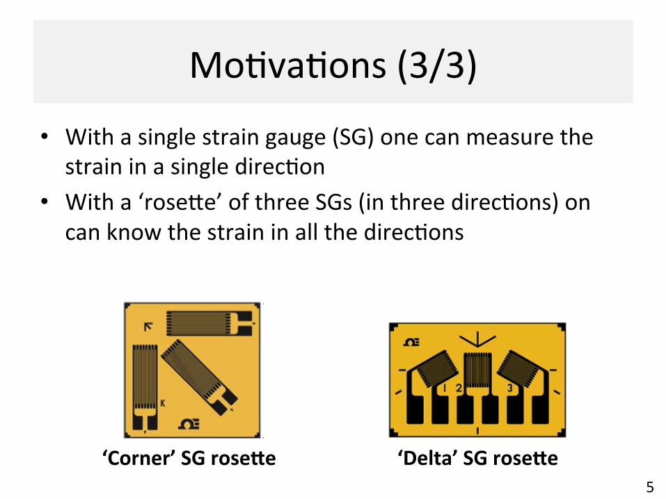
• With a single strain gauge (SG) one can measure the strain in a single direcAon
• With a ‘roseUe’ of three SGs (in three direcAons) on can know the strain in all the direcAons
5
‘Delta’ SG rose6e ‘Corner’ SG rose6e
Learning Outcomes When we have completed this unit (1 lecture + 1 tutorial), you should be able to:
• Use the elas8c cons8tu8ve law for homogeneous and isotropic solids to relate stresses (σ, τ) and strains (ε, γ)
• Use the Mohr’s circle to determine: – principal strains, and their direcAons; – maximum shear strain; – normal strain and shear strain in any direcAon
• Only the case of plane stress will be considered, i.e. no out-‐of-‐plane stresses
6
Further reading
• R C Hibbeler, “Mechanics of Materials”, 8th Ed, PrenAce Hall – Chapter 9 on “Stress TransformaAon”
• T H G Megson, “Structural and Stress Analysis”, 2nd Ed, Elsevier – Chapter 14 on “Complex Stress and Strain” (eBook)
7
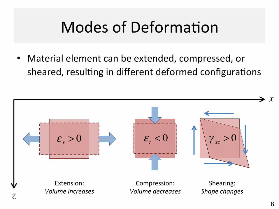
Modes of DeformaAon
• Material element can be extended, compressed, or sheared, resulAng in different deformed configuraAons
8
ε x > 0 ε z < 0 γ xz > 0
x
zExtension:
Volume increases Compression:
Volume decreases Shearing:
Shape changes
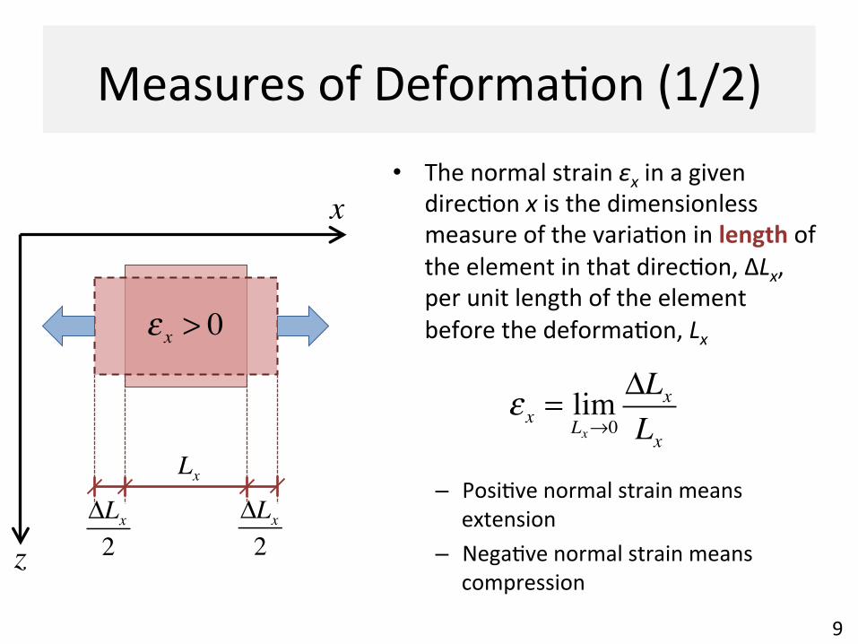
Measures of DeformaAon (1/2) • The normal strain εx in a given
direcAon x is the dimensionless measure of the variaAon in length of the element in that direcAon, ΔLx, per unit length of the element before the deformaAon, Lx
– PosiAve normal strain means extension
– NegaAve normal strain means compression
9
ε x > 0
LxΔLx2
ΔLx2
ε x = limLx→0ΔLxLx
x
z
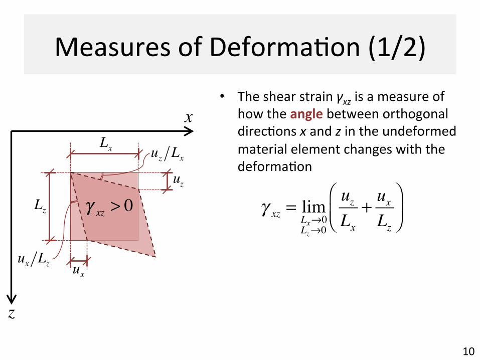
Measures of DeformaAon (1/2)
10
γ xz = limLx→0Lz→0
uzLx
+ uxLz
⎛⎝⎜
⎞⎠⎟
γ xz > 0
Lx
Lz
ux
uz
uz Lx
ux Lz
x
z
• The shear strain γxz is a measure of how the angle between orthogonal direcAons x and z in the undeformed material element changes with the deformaAon
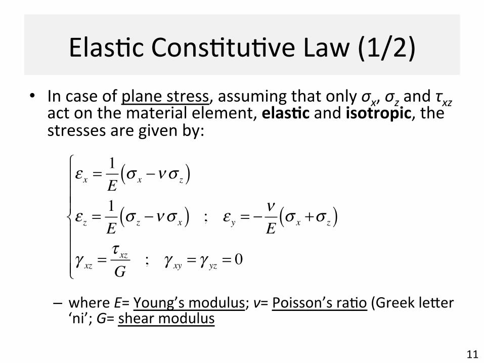
ElasAc ConsAtuAve Law (1/2)
11
• In case of plane stress, assuming that only σx, σz and τxz act on the material element, elas8c and isotropic, the stresses are given by:
– where E= Young’s modulus; ν= Poisson’s raAo (Greek leUer ‘ni’; G= shear modulus
ε x =1E
σ x −νσ z( )
ε z =1E
σ z −νσ x( ) ; ε y = − νE
σ x +σ z( )
γ xz =τ xz
G; γ xy = γ yz = 0
⎧
⎨
⎪⎪⎪
⎩
⎪⎪⎪

ElasAc ConsAtuAve Law (2/2)
12
• What does ‘elasAc’ mean? – The material is able to return to its original shape aCer loading and then unloading
• What does ‘isotropic’ mean? – The mechanical properDes of the material are idenDcal in all direcDons
• In presence of small deformaAons: – Concrete and steel are linear-‐elasDc and isotropic – Masonry and Dmber are linear-‐elasDc and ‘orthotropic’, meaning that there are three mutually orthogonally axes of symmetry for the mechanical properAes
Material TesAng (1/2)
13
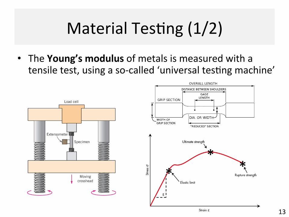
• The Young’s modulus of metals is measured with a tensile test, using a so-‐called ‘universal tesAng machine’
Material TesAng (2/2)
14
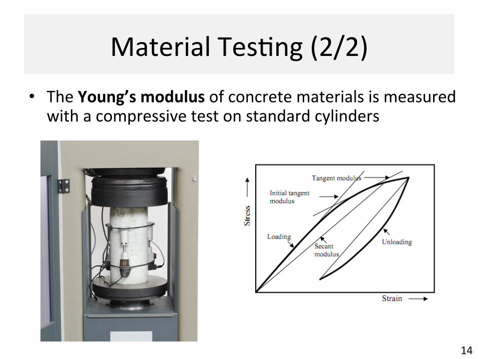
• The Young’s modulus of concrete materials is measured with a compressive test on standard cylinders
ElasAc Parameters
15
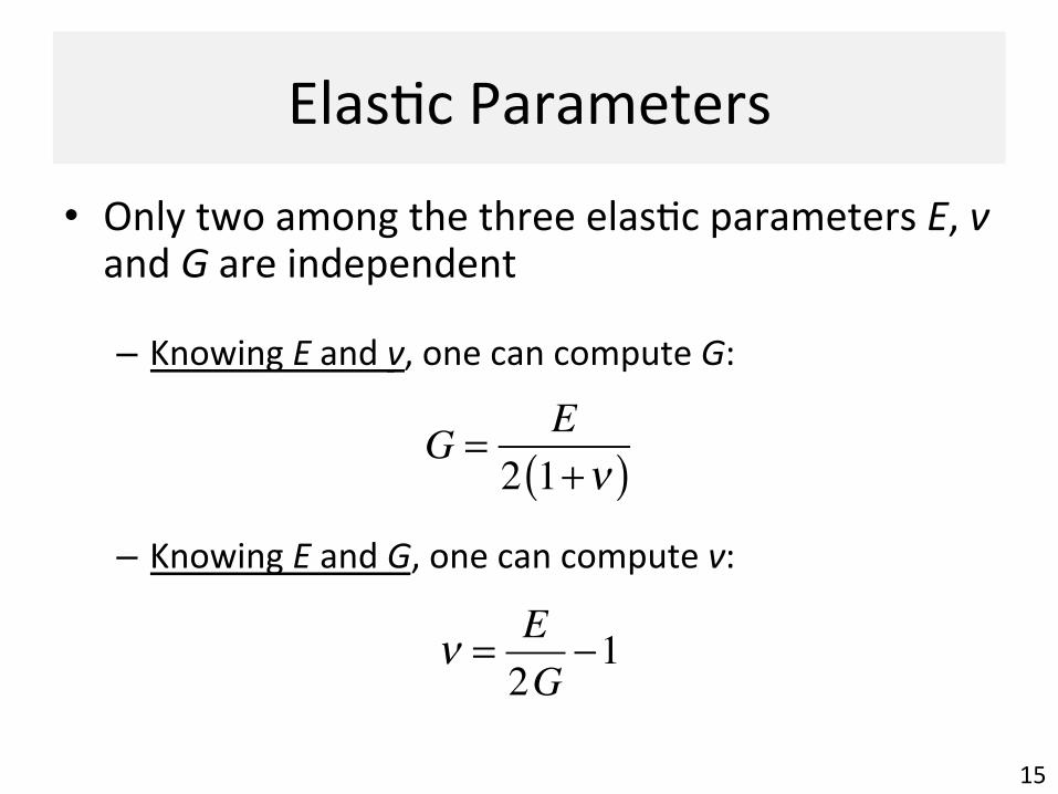
• Only two among the three elasAc parameters E, ν and G are independent
– Knowing E and ν, one can compute G:
– Knowing E and G, one can compute ν:
G = E2 1+ν( )
ν = E2G
−1

Mohr’s Circle of Strain
16
• Similarly to the case of complex stresses, complex strains (i.e. combined normal and shear strain) can be analysed with the Mohr’s circle
– Along the horizontal axis, the normal stress σ is replaced by the corresponding normal strain ε:
– Along the verAcal axis, the shear stress τ is replaced by half of the shear strain, γ/2, not γ:
σ → ε
τ → γ2
Mohr’s Circle of Strain (1/3)
17
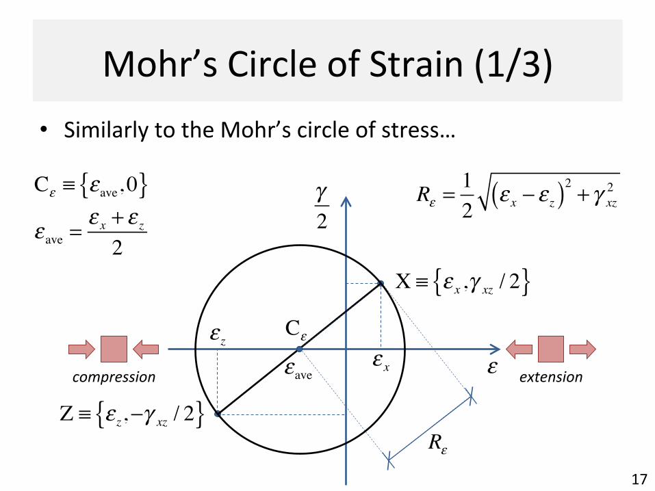
• Similarly to the Mohr’s circle of stress…
ε
Rε
extension compression
γ2
Cε
εave ε xε z
X ≡ ε x ,γ xz / 2{ }
Z ≡ ε z,−γ xz / 2{ }
εave =ε x + ε z2
Cε ≡ εave, 0{ } Rε =12
ε x − ε z( )2 + γ xz2

Mohr’s Circle of Strain (2/3)
18
extension compression
γ2
Cεεave εqε p
X
Z
εP Q
γ max
ε p = εave − Rε
εq = εave + Rε
⎧⎨⎩
γ max = 2Rε
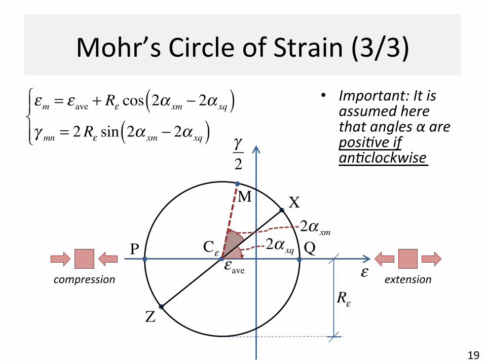
Mohr’s Circle of Strain (3/3)
19
extension compression
γ2
Cεεave
X
Z
εP Q
εm = εave + Rε cos 2α xm − 2α xq( )γ mn = 2Rε sin 2α xm − 2α xq( )⎧⎨⎪
⎩⎪
2α xq
2α xm
Rε
M
• Important: It is assumed here that angles α are posiDve if anDclockwise
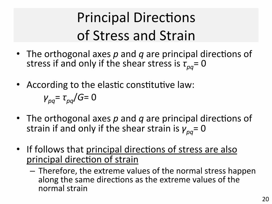
Principal DirecAons of Stress and Strain
20
• The orthogonal axes p and q are principal direcAons of stress if and only if the shear stress is τpq= 0
• According to the elasAc consAtuAve law: γpq= τpq/G= 0
• The orthogonal axes p and q are principal direcAons of strain if and only if the shear strain is γpq= 0
• If follows that principal direcAons of stress are also principal direcAon of strain – Therefore, the extreme values of the normal stress happen along the same direcAons as the extreme values of the normal strain

Strain-‐Gauge RoseUes (1/3) • One and only circle passes
through any three non-‐aligned points drawn in the plane
• It follows that: one and only one Mohr’s circle of strain can be drawn knowing the normal strain along three given direc8ons
• RoseUes made of three strain gauges exploit this property
• 45° (‘Corner’) Rose6e
21
!x
z
ε0
!ε90
ε45
!45°!45°
ε x = ε0 ; ε z = ε90γ xz = ε0 + ε90 − 2ε45
⎧⎨⎩

Strain-‐Gauge RoseUes (2/3) • 60° (‘Delta’) Rose6e
22
ε x =23
ε30 −ε902
+ ε150⎛⎝⎜
⎞⎠⎟
ε z = ε90
γ xz =23
ε150 − ε30( )
⎧
⎨
⎪⎪⎪
⎩
⎪⎪⎪
!ε30
!ε90
!ε150
30°60° 60°
!x
z
• Both corner and delta roseUes are largely used when tested structural elements under complex stress condiAons

Strain-‐Gauge RoseUes (2/3) Experimental validaDon of strut-‐and-‐De model for precast RC lintels • Strain was
experimentally measured using a corner roseRe
23
Corner rose(e
G. Robinson, A. Palmeri and S. AusAn, 8th RILEM InternaAonal Symposium on Fibre Reinforced Concrete, BEFIB 2012, Guimarães, Portugal, 2012
Key Learning Points 1. Knowing two of the three elasAc constant for elasAc isotropic
solids (E, ν and G), normal strains ε and shear strains γ can be computed for any plane stress state (σx, σz, τxz)
2. Similarly to the stresses, normal strains and shear strain on a given material element change their values depending on their direcAons
3. The Mohr’s circle of strain allows evaluaAng – The extreme values of the normal stress εp and εq – The extreme value of the shear stress γmax
– The inclinaAon where such values are seen – The stresses εm and γmn for an arbitrary inclinaAon
24


