Page 1
2014 VOL. 60 NO.167 Compliance with Tier 4 Final Emissions Regulations Development of 125 mm and 140 mm Bore Engines
― 1 ―
Technical Paper
Compliance with Tier 4 Final Emissions Regulations Development of 125 mm and 140 mm Bore Engines
Hiroshi Ohta
Shouhei Nagasaka
Takashi Katou
Tier 4 Final emissions regulations, effective from January 2014, require that nitrogen oxides (NOx) in emis-sions be reduced by 80% over the level required by the previous standards. In just three years from the imple-mentation of Tier 4 Interim emissions regulations in January 2011, new 11-liter and 15-liter engines with new technologies were developed and launched that meet the latest, much more stringent emissions regulations while maintaining the same or better performance, durability and reliability over the previous engines. This paper in-troduces these new engines.
Key Words: Construction Equipment, Diesel Engine, Emissions Regulations, NOx Reduction Aftertreatment System, Urea Solution
1. Introduction
Diesel engines are used for a wide range of industrial ap-
plications as they are highly durable and reliable, are available
in various sizes from small to large, therefore offering various
power ranges, and have high thermal efficiency. On the other
hand, nitrogen oxides (hereafter “NOx”) and particulate mat-
ter (hereafter “PM”) that are emitted from diesel engines are
known to have negative impact on the environment and or-
ganisms.
Since 1996, as part of efforts to stem the impact, emis-
sions regulations for diesel engines on construction equipment
have been made increasingly stringent worldwide. These ef-
forts, particularly in construction and mining, have been led
by the Japanese, US and European authorities.
To clear EPA Tier 4 Final and EU Stage IV regulations,
both effective since January 2014, and Japan’s off-road emis-
sions regulations for designation of low-emission construction
equipment which became effective in October 2014 (hereafter
the underlined parts are collectively referred to as “Tier 4
Final emissions regulations”), the new engines that are de-
scribed in this paper incorporate the existing, and now up-
graded, proven technologies that were originally introduced to
clear EPA Tier 4 Interim and EU Stage III B regulations, both
put in place in January 2011, and Japan’s off-road emissions
regulations for designation of low-emission construction
equipment which became effective in October 2011 (hereafter
the underlined parts are collectively referred to as “Tier 4
Interim emissions regulations”). In addition to these technol-
ogies, the new engines employ a new aftertreatment technol-
ogy for NOx reduction. This paper provides an overview of
Komatsu’s new 11-liter and 15-liter engines compliant to Tier
4 Final emissions regulations, focusing on their technical fea-
tures.
2. Emissions regulations for diesel engines on construction equipment
As described above, emissions regulations for diesel en-
gines on construction equipment were made more stringent in
2014 with the introduction of Tier 4 Final.
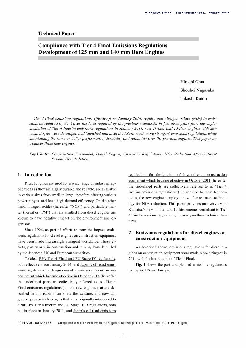
Fig. 1 shows the past and planned emissions regulations
for Japan, US and Europe.
Page 2
2014 VOL. 60 NO.167 Compliance with Tier 4 Final Emissions Regulations Development of 125 mm and 140 mm Bore Engines
― 2 ―
Fig. 1 Emissions standards in Japan, US and Europe
Fig. 2 shows a historical review of EPA standards on
NOx and PM from Tier 1 to Tier 4. Standards have been made
more stringent every five years, with NOx, PM and other key
contaminants required to be cut by around 30% at every Tier
progression. Tier 4 Interim, introduced in January 2011, re-
quired a 50% reduction in NOx and a 90% reduction in PM
from Tier 3. Komatsu cleared the Tier 4 Interim hurdles with
the introduction of a new aftertreatment system and other
techniques.
Tier 4 Final requires an 80% reduction in NOx while
maintaining the same standard for PM. Komatsu meets the
requirement with the introduction of an NOx reduction after-
treatment technology.
Fig. 2 Historical review of EPA emissions standards
Emissions from diesel engines on construction equipment
have traditionally been measured in steady-state 8 modes, or
C1 mode in ISO 08178.
With Tier 4 Interim, introduced in 2011, came a new
measurement requirement. That is nonroad transient cycle test.
Emissions now need to be measured in both of these modes
and clear the standards.
To clear the nonroad transient cycle measurement stand-
ards in Tier 4 Final, it is extremely important for the new NOx
reduction aftertreatment system to operate highly accurately.
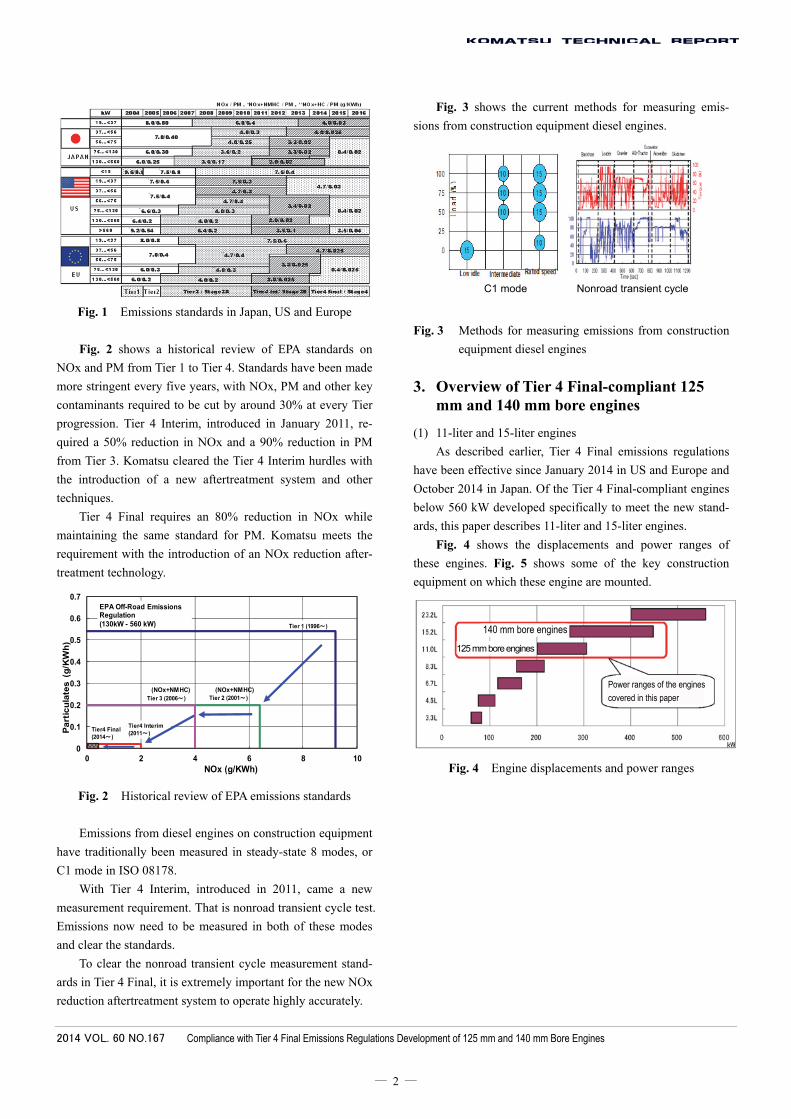
Fig. 3 shows the current methods for measuring emis-
sions from construction equipment diesel engines.
Fig. 3 Methods for measuring emissions from construction
equipment diesel engines
3. Overview of Tier 4 Final-compliant 125 mm and 140 mm bore engines
(1) 11-liter and 15-liter engines
As described earlier, Tier 4 Final emissions regulations
have been effective since January 2014 in US and Europe and
October 2014 in Japan. Of the Tier 4 Final-compliant engines
below 560 kW developed specifically to meet the new stand-
ards, this paper describes 11-liter and 15-liter engines.
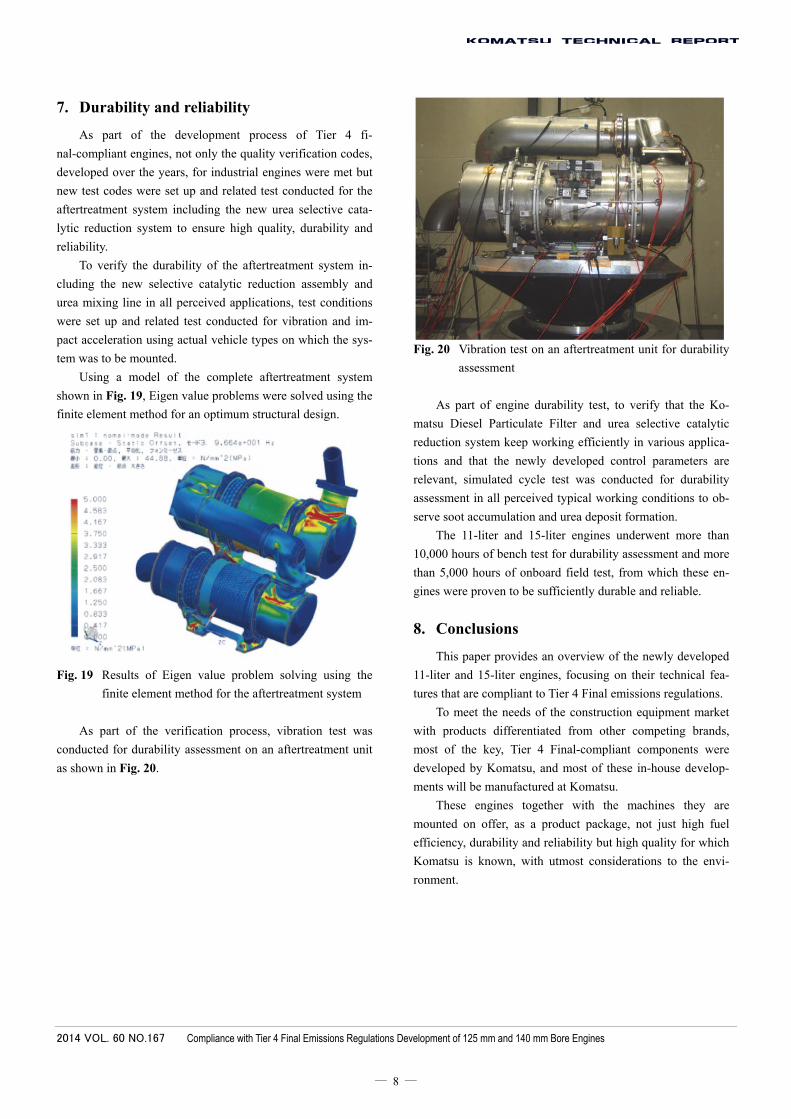
Fig. 4 shows the displacements and power ranges of
these engines. Fig. 5 shows some of the key construction
equipment on which these engine are mounted.
Fig. 4 Engine displacements and power ranges
0
0.1
0.2
0.3
0.4
0.5
0.6
0.7
0 2 4 6 8 10
Part
icu
late
s (
g/K
Wh
)
NOx (g/KWh)
Tier 1 (1996~)
Tier 2 (2001~)Tier 3 (2006~)
Tier4 Interim (2011~)
Tier4 Final(2014~)
(NOx+NMHC) (NOx+NMHC)
EPA Off-Road Emissions Regulation(130kW - 560 kW)
140 mm bore engines
125 mm bore engines
Power ranges of the engines
covered in this paper
C1 mode Nonroad transient cycle
Page 3
2014 VOL. 60 NO.167 Compliance with Tier 4 Final Emissions Regulations Development of 125 mm and 140 mm Bore Engines
― 3 ―
Fig. 5 Key applications for the 125/140 mm bore engines
(2) Objectives in the development of Tier 4 Final-compliant
engines
(a) Clear Tier 4 Final emissions regulations in Japan,
US and Europe
(b) Same or less fuel consumption than the previous
engines while minimizing the consumption of urea
solution
(c) Minimize changes to the base engine design and
utilize the existing Tier 4 Interim ancillary technol-
ogies
(d) Maintain durability and reliability in demanding
operating conditions
Table 1 shows the technologies incorporated to clear the
emissions regulations. Table 2 shows some of the key tech-
nologies employed to meet the objectives.
Table 1 Technologies to clear emissions regulations Regulations Technology
Tier 2 (1) Air cooled aftercooler + (2) High pressure fuel injection (120 MPa)
Tier 3 (1) Air cooled aftercooler + (2)’ High pressure fuel injection (160 MPa) + (3) Exhaust Gas Recirculation
Tier 4 Interim
(1) Air cooled aftercooler + (2)’’ High pressure fuel injection (200 MPa) + (3)’ Exhaust Gas Recirculation + (4) Variable geometry turbocharger + (5) Komatsu Diesel Particulate Filter
Tier 4 Final
(1) Air cooled aftercooler + (2)’’ High pressure fuel injection (200 MPa) + (3)’ Exhaust Gas Recirculation + (4) Variable geometry turbocharger + (5)’ Komatsu Diesel Particulate Filter + (6) Selective Catalytic Reduction
Table 2 Key technologies on the 11-liter and 15-liter engines Tire 4 Interim Tier 4 Final
Engine model unit SAA6D125E-6 SAA6D140E-6 SAA6D125E-7 SAA6D140E-7
No. of cylinders - 6 Bore x Stroke mm 125×150 140×165 125×150 140×165 Displacement L 11.04 15.24 11.04 15.24
Fuel injection - Common rail system Max. fuel injection pressure
MPa 180 200 180 200
Combustion chamber
- New combustion chamber ←
Turbocharger - Variable geometry ← Exhaust Gas Recirculation
- Standard (Fins & Tubes) ←
Controller - CM2250 CM2350 Blow-by gas - Positive crankcase ventilation ←
Aftertreatment - Komatsu Diesel Particulate
Filter
Komatsu Diesel Particulate Filter+Selective Catalytic Reduc-
tion
In the new engine development project, the biggest hur-
dle was to develop a selective catalytic reduction system to
reduce NOx by at least 80%.
To complete the project within the shorter, 3-year period
and ensure the same or better engine performance, durability
and reliability over the previous engines, Komatsu’s proven
Tier 4 Interim technologies have been retained for the base
engine parts and other key areas.
The key technologies incorporated in the new engines in-
clude electronically controlled common rail system that oper-
ates at higher pressure, variable geometry turbocharger, more
accurately controlled exhaust gas recirculation valve, larger
exhaust gas recirculation cooler, and Komatsu Closed Crank-
case Ventilation that sends blow-by gas back to the air intake
Dozers Excavators Wheel loaders
Trucks Articulated trucks Motor graders
Page 4
2014 VOL. 60 NO.167 Compliance with Tier 4 Final Emissions Regulations Development of 125 mm and 140 mm Bore Engines
― 4 ―
system without releasing it out to the atmosphere.
Fig. 6 shows the SAA6D125E-7 engine for hydraulic
excavators. Fig. 7 shows the SAA6D140E-7 engine for doz-
ers.
Fig. 6 Tier 4 Final-compliant SAA6D125E-7 engine
Fig. 7 Tier 4 Final-compliant SAA6D140E-7 engine
4. Tier 4 Final-compliant engine technologies
The following paragraphs describe the key components
of the Tier 4 Final-compliant engines that contribute to clear-
ing the latest emissions regulations in Japan, US and Europe,
and at the same time offering the same or better performance
(in power and fuel consumption) over the previous engines,
which is one of the new engine development objectives.
(1) Combustion system
The electronically controlled common rail fuel injection
system with maximum injection pressure of 200 MPa and the
new combustion chamber, both originally introduced on the
Tier 4 Interim engines, have been retained on the new engines,
which were then tuned for maximum performance. With the
addition of a selective catalytic reduction system in the after-
treatment system, the new engines achieve the same or less
fuel consumption and the same level of PM emission over the
previous engines, although urea solution consumption has
been added. Fig. 8 shows a comparison of fuel consumptions
by 15-liter engines.
Fig. 8 Comparison of fuel consumptions by 15-liter engines
(2) Exhaust gas recirculation valve
The hydraulically driven exhaust gas recirculation valve
with a hydraulic servo system, developed for the Tier 4 In-
terim-compliant engines, has been retained. Fig. 9 shows an
external view of the compact, highly accurate and reliable
exhaust gas recirculation valve.
Fig. 9 External view of the exhaust gas recirculation valve
(3) Exhaust gas recirculation cooler
Fig. 10 shows the external view and structure of the high
capacity exhaust gas recirculation cooler developed for the
Control valve Oil inlet
Stroke sensor
Hydraulic servo actuator
Hydraulic actuator assembly
Valve assembly
Valve
Valve body
Specific fuel consumption [g/kWh]
Urea solution consumption
Fuel consumption
Page 5
2014 VOL. 60 NO.167 Compliance with Tier 4 Final Emissions Regulations Development of 125 mm and 140 mm Bore Engines
― 5 ―
Tier 4 Interim-compliant engines. To substantially reduce
NOx, it is essential to sufficiently cool exhaust gas being re-
circulated in large volume.
To achieve that, the previous multitubular design has
been changed to the new design of fins and tubes where fins
are arranged between the tubes in the gas channel.
Fig. 10 External view and structure of the exhaust gas recir-
culation cooler
(4) Variable geometry turbocharger
The variable geometry turbocharger with a sliding-nozzle
design to vary the channel size, developed for the Tier 4 In-
terim-compliant engines, has been retained.
As with the exhaust gas recirculation valve described ear-
lier, Komatsu’s exclusive hydraulic drive technology is used
to move the sliding system.
The variable geometry design enables exhaust gas recir-
culation across a wide operating range, helping to improve
fuel consumption and acceleration and thus contributing
greatly to overall product performance upgrade. Fig. 11 shows
the structure of the variable geometry turbocharger.
Fig. 11 Structure of the variable geometry turbocharger
(5) Komatsu Closed Crankcase Ventilation
The Komatsu Closed Crankcase Ventilation system, de-
veloped for the Tier 4 Interim-compliant engines, has been
retained.
The compact, highly reliable Komatsu Closed Crankcase
Ventilation filter features a highly rigid aluminum body which
can withstand severe operating conditions of construction
equipment, a pressure regulating valve which prevents crank-
case pressure drop caused by vacuum upstream of the turbo
inlet, and a pressure sensor for detecting a clogged filter. Fig.
12 shows the external view of the Komatsu Closed Crankcase
Ventilation system.
Fig. 12 External view of the Komatsu Closed Crankcase
Ventilation system
5. Aftertreatment system
The Komatsu Diesel Particulate Filter was developed for
our Tier 4 Interim-compliant engines to capture and remove
soot in exhaust gas.
Fig. 13 shows the internal structure of the filter.
Fig. 13 Structure of the Komatsu Diesel Particulate Filter
In addition to the Komatsu Diesel Particulate Filter, to
reduce NOx by at least 80%, a requirement in Tier 4 Final
emissions regulations, the new engines are equipped with a
urea selective catalytic reduction system.
The system breaks down NOx in exhaust gas into harm-
less nitrogen (N2) and water (H2O).
As shown in Fig. 14, urea solution is injected into ex-
haust gas, and NOx reacts with ammonia in the solution
within the selective catalytic reduction catalyst and is broken
down into nitrogen and water.
Oxidation catalyst
Soot filter
Blow-by gas inlet
Pressure regulating valve
Blow-by gas outlet
Oil drain
Filter casing
Aluminum body
Pressure sensor
Stroke sensor
Intake air
Exhaust gas
Nozzle ring
Gas outlet
Water outlet
Water inlet
Air vent
Viewed from Z
Gas inlet Tube
FinGas inlet
Page 6
2014 VOL. 60 NO.167 Compliance with Tier 4 Final Emissions Regulations Development of 125 mm and 140 mm Bore Engines
― 6 ―
Fig. 14 Chemical reactions in urea selective catalytic reduc-
tion
As shown in Fig. 15, the urea selective catalytic reduc-
tion system primarily consists of the urea solution distribution
system which injects urea solution into exhaust gas, the urea
solution mixing line which breaks down the injected urea
solution into ammonia and dissipates the ammonia in exhaust
gas, and the selective catalytic reduction assembly which
houses the selective catalytic reduction catalyst that facilitates
the dissolution of NOx.
Fig. 15 Urea selective catalytic reduction system is equipped
(1) Urea solution distribution system
The urea solution distribution system consists of the urea
solution tank, the urea solution pump and the urea solution
injector.
Urea solution is pressurized by the urea solution pump
and is injected by the urea solution injector into exhaust gas.
If the amount of urea solution injected into exhaust gas is too
small, not all NOx is broken down and the NOx that remains
undissolved is discharged into the atmosphere. If the amount
of urea solution injected into exhaust gas is too much, the
excessive urea solution forms deposits of urea in the exhaust
pipe while the excessive ammonia is discharged into the at-
mosphere.
Engine speed and power change as load on the construc-
tion machine on which the engine is mounted changes. And as
that happens, the amount of NOx in exhaust gas changes ac-
cordingly. The urea solution distribution system keeps moni-
toring the operating status of the engine and selective catalytic
reduction assembly to ensure that appropriate amounts of urea
solution are injected at all times.
The urea solution freezes at -11˚C. To be able to thaw the
solution or keep it warm enough for machines working in
freezing conditions, the hosing going out and into the urea
solution tank and pump incorporates heating wire.
(2) Urea solution mixing line
In the urea solution mixing line, urea solution that has
been injected into exhaust gas is broken down into ammonia
and dissipated evenly in the exhaust gas before reaching the
selective catalytic reduction catalyst. If the mixing line has a
complex internal structure to dissipate ammonia evenly, de-
posits of urea can form inside the mixing line. To prevent that
and achieve even and efficient dispersion in a limited space
on a construction machine, the internal structure of the mixing
line has been designed appropriately using computational
fluid dynamics analysis. Fig. 16 shows an example of com-
putational fluid dynamics analysis for the mixing line.
Fig. 16 Example of computational fluid dynamics analysis
for the mixing line
(3) Selective catalytic reduction assembly
The selective catalytic reduction assembly houses the se-
lective catalytic reduction catalyst which allows NOx in the
exhaust gas and ammonia generated through the dissolution of
urea solution to react with each other and facilitates the dis-
solution of the NOx into harmless nitrogen and water. In the
process, ammonia adheres to the selective catalytic reduction
catalyst and NOx in the exhaust gas reacts with the ammonia,
as shown in Fig. 17.
Urea solution distribution system
Urea solution pump
Urea solution injector
Urea solution mixing line
Urea solution tank
Selective catalytic reduction ass'y
Engine
①Oxidation catalyst ③ Urea solution injection
nozzle ⑤ Ammonia oxidation
catalyst
④ Selective catalytic reduction catalyst
CleanExhaust
②Soot filter
①Reactions in the oxidation catalyst
②Reactions in the soot filter
③Reactions of the urea solution
④ Reactions in the selective catalytic reduction catalyst
⑤Reaction in the ammonia oxidation catalyst
Dissipates evenly in the mixing line
Flow of exhaust gas
Page 7
2014 VOL. 60 NO.167 Compliance with Tier 4 Final Emissions Regulations Development of 125 mm and 140 mm Bore Engines
― 7 ―
Fig. 17 Reduction of NOx by the selective catalytic reduc-
tion catalyst
By increasing the amount of ammonia that adheres to the
selective catalytic reduction catalyst, more NOx can be re-
duced. Onboard sensors are used to monitor the operating
status of the selective catalytic reduction assembly, and based
on the input from the sensors including the amount of ammo-
nia adhering to the catalyst, the amount of ammonia that re-
acts with NOx and the amount of NOx coming from the en-
gine, the optimum injection volume of urea solution is deter-
mined.
An ammonia oxidation catalyst is provided downstream
of the selective catalytic reduction catalyst to prevent unre-
acting ammonia from being released out the exhaust pipe into
the atmosphere.
As with the oxidation catalyst and soot filter in the Ko-
matsu Diesel Particulate Filter, these catalysts are carried on
ceramic substrates, which are held in place by a mat made of
special, highly heat resistant fiber and housed in a metal cas-
ing. This design is modeled after the Komatsu Diesel Particu-
late Filter that was launched in 2011 and has since proven its
high durability and reliability in the severe, shock load-prone
operating environment of construction equipment.
Fig. 18 shows the internal structure of the selective cata-
lytic reduction assembly.
Fig. 18 Internal structure of the selective catalytic reduction
assembly
Generally, construction equipment operates under repeti-
tive load more than commercial vehicles and passenger cars,
causing its exhaust gas to be hotter, thus facilitating chemical
reactions more easily in aftertreatment. The Komatsu Diesel
Particulate filter, urea mixing line and selective catalytic re-
duction assembly are all heat insulated to minimize tempera-
ture drop inside these units, thus maximizing the effect of hot
exhaust gas. Even in light load applications and low ambient
temperature, the heat insulation design helps maximize the
units’ PM and NOx reducing performance.
The Komatsu Diesel Particulate filter, urea mixing line
and selective catalytic reduction assembly are all manufac-
tured at Komatsu to ensure high quality.
6. Electronic control system
With the Tier 4 Final-compliant engines, the urea selec-
tive catalytic reduction system has been added to the elec-
tronic control system to enable its highly accurate control. A
newly developed engine control unit has replaced its prede-
cessor to ensure coordinated control of the selective catalytic
reduction system with the Tier 4 Interim-compliant technolo-
gies including the electronically controlled common rail fuel
injection system, variable geometry turbocharger and Ko-
matsu Diesel Particulate Filter and to maintain optimum
high-speed communication between these units and other
onboard electronic systems.
To meet the selective catalytic reduction inducement re-
quirements under Tier 4 Final regulations, engine and after-
treatment diagnostics has been introduced to upgrade the
troubleshooting system and minimize downtime.
Upstream NOx
Injected NH3
①NH3 adhesion
②NOx reacts with NH3. (NOx reduction)
NH3 slip
Downstream NOx
③ NH3 release
Ammonia adhesion control
The amount of ammo-nia adhesion needs to be optimized.
Ammonia oxidation catalyst
Selective Catalytic Reduction catalyst
Page 8
2014 VOL. 60 NO.167 Compliance with Tier 4 Final Emissions Regulations Development of 125 mm and 140 mm Bore Engines
― 8 ―
7. Durability and reliability
As part of the development process of Tier 4 fi-
nal-compliant engines, not only the quality verification codes,
developed over the years, for industrial engines were met but
new test codes were set up and related test conducted for the
aftertreatment system including the new urea selective cata-
lytic reduction system to ensure high quality, durability and
reliability.
To verify the durability of the aftertreatment system in-
cluding the new selective catalytic reduction assembly and
urea mixing line in all perceived applications, test conditions
were set up and related test conducted for vibration and im-
pact acceleration using actual vehicle types on which the sys-
tem was to be mounted.
Using a model of the complete aftertreatment system
shown in Fig. 19, Eigen value problems were solved using the
finite element method for an optimum structural design.
Fig. 19 Results of Eigen value problem solving using the
finite element method for the aftertreatment system
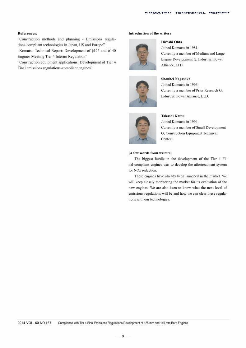
As part of the verification process, vibration test was
conducted for durability assessment on an aftertreatment unit
as shown in Fig. 20.
Fig. 20 Vibration test on an aftertreatment unit for durability
assessment
As part of engine durability test, to verify that the Ko-
matsu Diesel Particulate Filter and urea selective catalytic
reduction system keep working efficiently in various applica-
tions and that the newly developed control parameters are
relevant, simulated cycle test was conducted for durability
assessment in all perceived typical working conditions to ob-
serve soot accumulation and urea deposit formation.
The 11-liter and 15-liter engines underwent more than
10,000 hours of bench test for durability assessment and more
than 5,000 hours of onboard field test, from which these en-
gines were proven to be sufficiently durable and reliable.
8. Conclusions
This paper provides an overview of the newly developed
11-liter and 15-liter engines, focusing on their technical fea-
tures that are compliant to Tier 4 Final emissions regulations.
To meet the needs of the construction equipment market
with products differentiated from other competing brands,
most of the key, Tier 4 Final-compliant components were
developed by Komatsu, and most of these in-house develop-
ments will be manufactured at Komatsu.
These engines together with the machines they are
mounted on offer, as a product package, not just high fuel
efficiency, durability and reliability but high quality for which
Komatsu is known, with utmost considerations to the envi-
ronment.
Page 9
2014 VOL. 60 NO.167 Compliance with Tier 4 Final Emissions Regulations Development of 125 mm and 140 mm Bore Engines
― 9 ―
References:
“Construction methods and planning - Emissions regula-
tions-compliant technologies in Japan, US and Europe”
“Komatsu Technical Report: Development of ϕ125 and ϕ140
Engines Meeting Tier 4 Interim Regulation”
“Construction equipment applications: Development of Tier 4
Final emissions regulations-compliant engines”
Introduction of the writers
Hiroshi Ohta
Joined Komatsu in 1981.
Currently a member of Medium and Large
Engine Development G, Industrial Power
Alliance, LTD.
Shouhei Nagasaka
Joined Komatsu in 1996.
Currently a member of Prior Research G,
Industrial Power Alliance, LTD.
Takashi Katou
Joined Komatsu in 1994.
Currently a member of Small Development
G, Construction Equipment Technical
Center 1
[A few words from writers]
The biggest hurdle in the development of the Tier 4 Fi-
nal-compliant engines was to develop the aftertreatment system
for NOx reduction.
These engines have already been launched in the market. We
will keep closely monitoring the market for its evaluation of the
new engines. We are also keen to know what the next level of
emissions regulations will be and how we can clear these regula-
tions with our technologies.