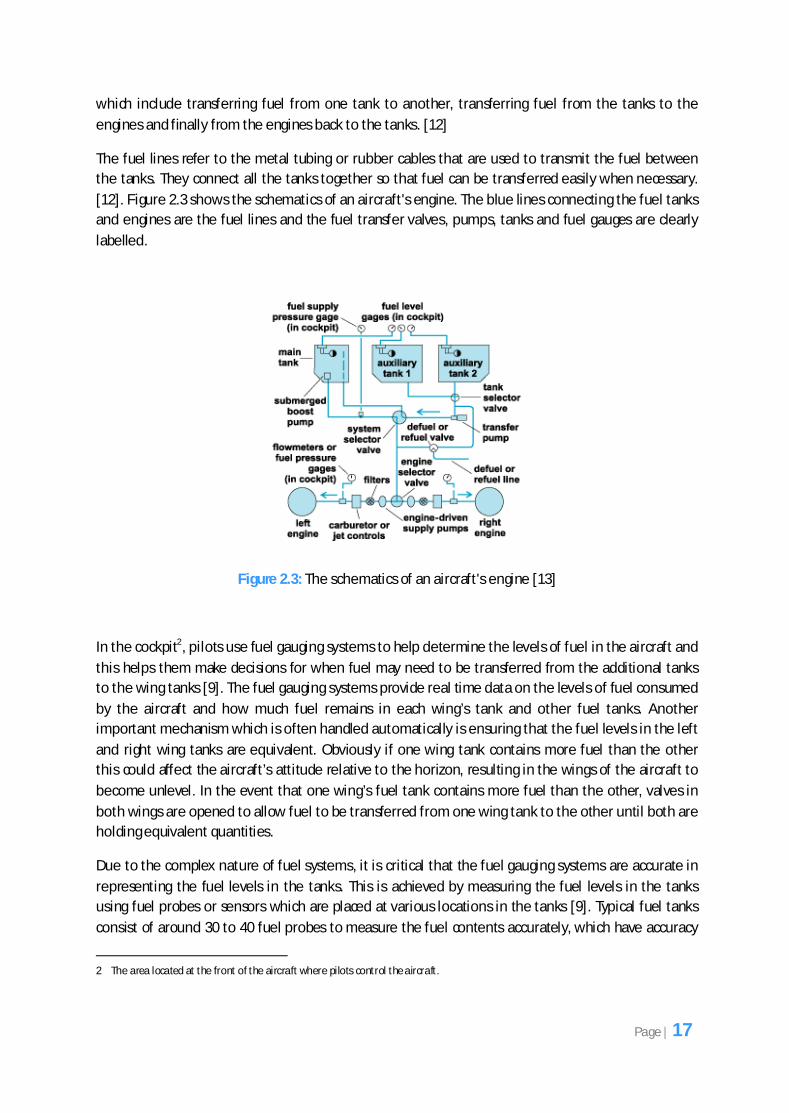
Component-Based Software for the Avionics Domain A dissertation submitted to the University of Manchester for the degree of Master of Science in the Faculty of Engineering and Physical Sciences 2010 By Gurdeep Singh Kang School of Computer Science
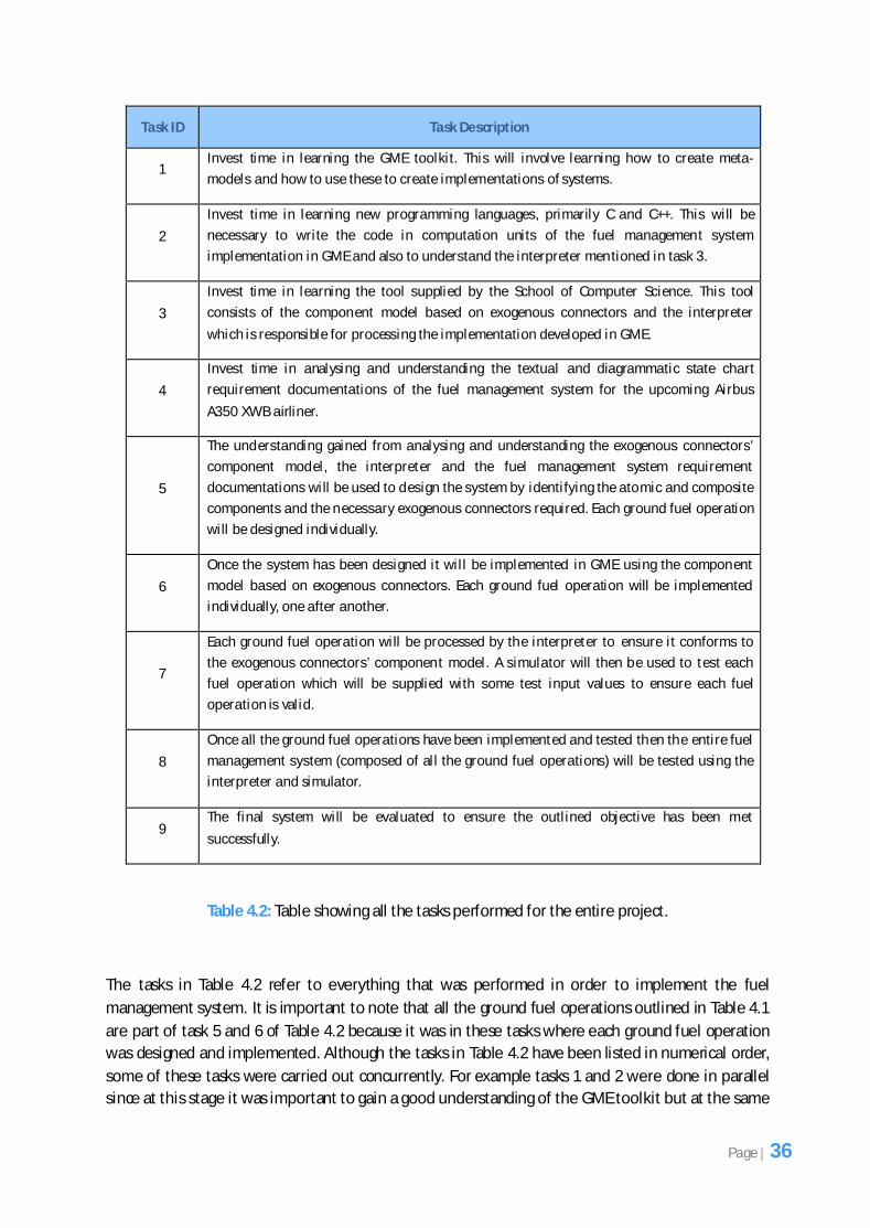
Transcript
Component-Based Software for
the Avionics Domain
A dissertation submitted to the University of Manchester for the degree of Master of Science in the Faculty of Engineering and
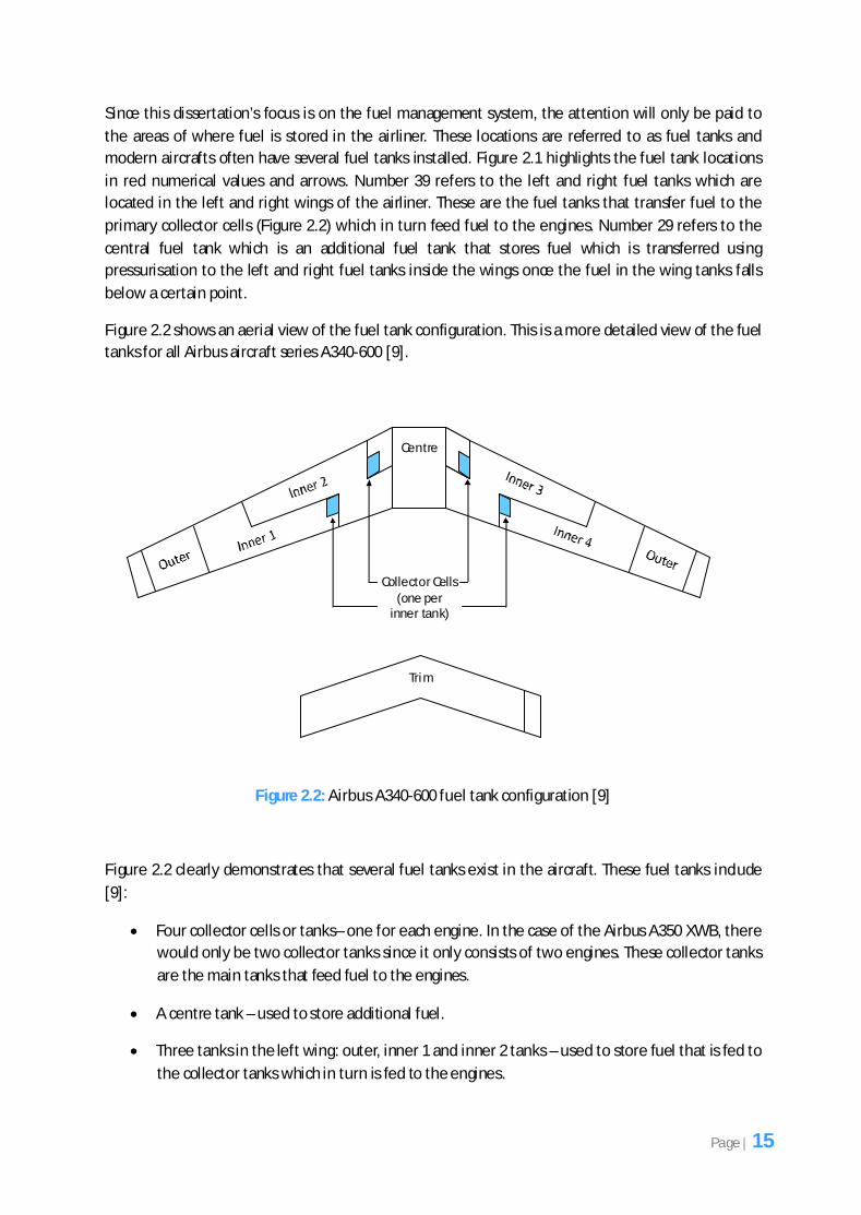
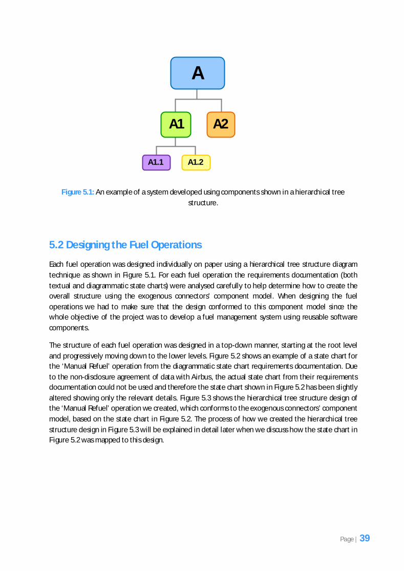
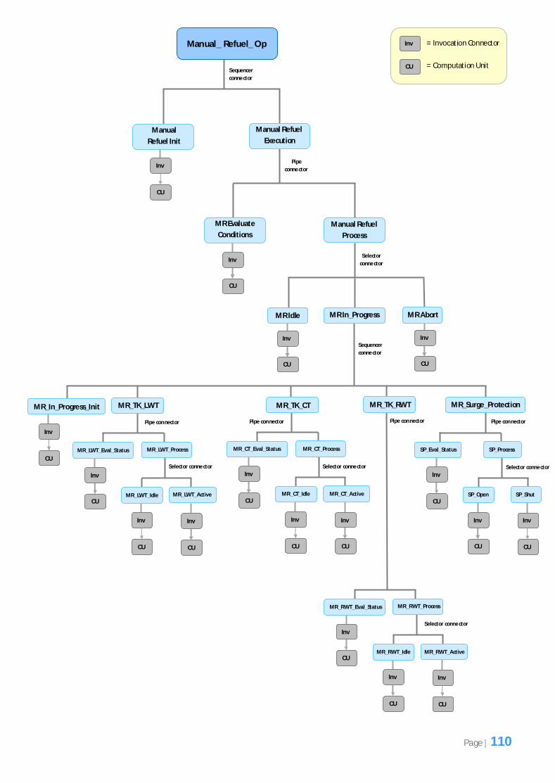
Figure 5.3: Hierarchical tree structure design for the ‘Manual Refuel’ operation.
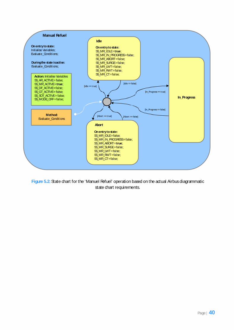
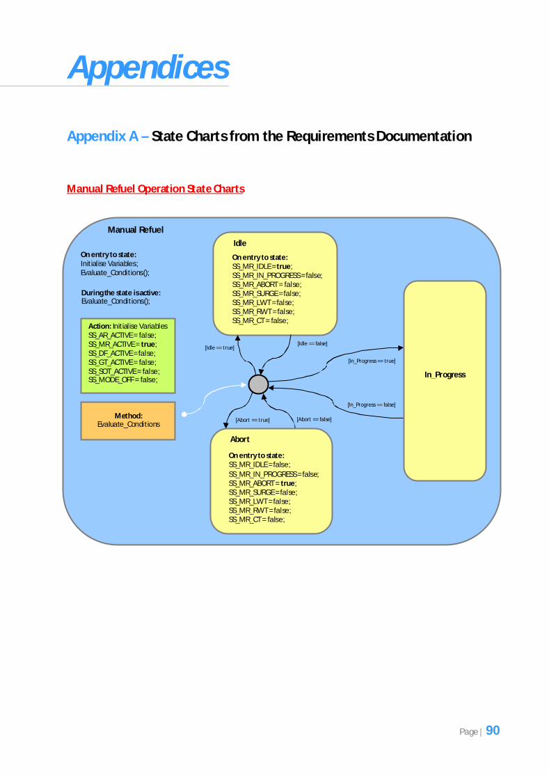
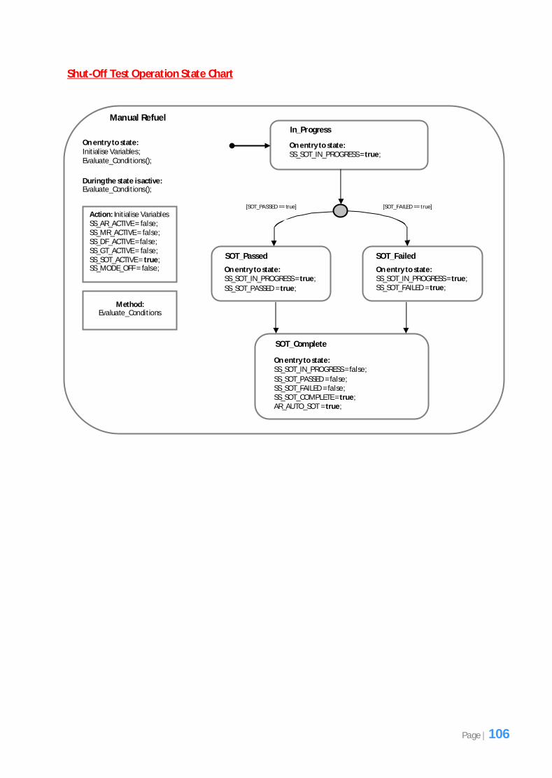
Notice that in Figure 5.2 the top level state is called ‘Manual Refuel’ and this state consists of 3 sub-
states called ‘Idle’, In_Progress’ and ‘Abort’. The ‘Manual Refuel’ state also consists of an ‘Initialise
Variables’ action and an ‘Evaluate_Conditions’ method. Before discussing how this fuel operation
was designed in Figure 5.3, it would be useful to briefly mention the purpose of the ‘Initialise
Variables’ action and the ‘Evaluate_Conditions’ method as these are present in all the fuel operation
state charts in the diagrammatic state chart requirements documentation.
The ‘Initialise Variables’ action refers to what happens as soon as the ‘Manual Refuel’ state becomes
active. When we say active we mean the state will be executed. The keyword ‘On Entry to State’
indicates that as soon as this state is active, initialise some variables. These variables are system state
variables and determine which fuel operation is active at any time and only one fuel operation can
be active at any time. These system state variables are of boolean type and if the ‘Manual Refuel’
state has been selected then on entry to this state when the ‘Initialise Variables’ action is executed
the system state variable called ‘SS_MR_ACTIVE’ will be set to true and the other 5 system state
variables that represent the other fuel operations will be set to false, as is clearly demonstrated in
Figure 5.2. It is important to note that the ‘Initialise Variables’ action is only present at the top level
state of each fuel operation, it does not appear elsewhere in the lower sub-states. Its purpose is to
just initialise the system state variables so that the current fuel operation being executed is known.
Inv
CU
Inv
CU
Manual Refuel Op
MR Evaluate
Conditions
Sequencer
conne ctor
Manual
Refuel Init
Pipe
conne ctor
Manual Refuel
Execution
Selector conne ctor
Manual Refuel
Process
MR Idle MR In_Progress MR Abort
= Invocation Connector Inv
CU = Computation Unit
.
.
Other components
omitted
Page | 41
The ‘Evaluate_Conditions’ method is simply a method that determines which sub-state (‘Idle’,
‘In_Progress’ or ‘Abort’) in the ‘Manual Refuel’ state will be active. The method performs some
computation based on the values of particular variables (not shown in Figure 5.2) that have been
supplied to the method and determines which sub-state should be executed. The actual sub-state
that is executed depends on the value of the 3 different variables that are located near the transition
lines of the states in square brackets of Figure 5.2. These 3 variables are set and output when the
‘Evaluate_Conditions’ method is computed. Whichever variable is true is the sub-state that is
executed.
The requirements documentation of the ‘Manual Refuel’ state indicates that only one sub-state at
any time can execute. This is indicated by a solid line around the state box in Figure 5.2. If multiple
states can execute concurrently then this is represented by a dotted line around the state box. An
example of this will be discussed later. Notice that the ‘Evaluate_Conditions’ method is executed on
entry to the ‘Manual Refuel’ state and during the time the ‘Manual Refuel’ state is active. The
keyword ‘During the state is active’ in Figure 5.2 indicates this. The ‘Evaluate_Conditions’ method
must constantly be executed whilst the ‘Manual Refuel’ state is active in order to determine which
sub-state to execute next.
Now that the notation of the state charts has been briefly explained we will discuss how the design
for one of the fuel operations (‘Manual Refuel’) shown in Figure 5.3 was created based on the state
chart in Figure 5.2.
When it came to designing the ‘Manual Refuel’ operation, creating a hierarchical tree structure
design was not entirely straight-forward. Due to the way the exogenous connectors’ component
model was developed, it was not always possible to directly map the requirements in the state charts
to the design. In this case we had to use our own initiative to find a way in which we could design the
structure without affecting the functionality originally outlined in the requirements.
Each state in Figure 5.2 and each component in Figure 5.3 have a corresponding colour code to help
understand the mapping process of how each state was mapped and represented in the hierarchical
tree structure design. This will help simplify how the mapping process was undertaken for the
‘Manual Refuel’ operation which will be discussed in a step-by-step manner.
Mapping the ‘Manual Refuel’ state in Figure 5.2 was relatively straight forward since this is the top
level state for this fuel operation. It was mapped to the ‘Manual Refuel Op’ composite component in
Figure 5.3. Since the ‘Initialise Variables’ action in Figure 5.2 would take place as soon as the ‘Manual
Refuel’ state became active it was important to ensure that this was represented as the first sub-
component of the ‘Manual Refuel Op’ composite component in the hierarchical tree structure shown
in Figure 5.3. This component was named ‘Manual Refuel Init’ and this is an atomic component
because it will not be composed of other sub-components. Note that although the ‘Initialise
Variables’ action is responsible for initialising the system state variables, this had to be represented
inside an atomic component in Figure 5.3 because this is the rule of the exogenous connectors’
component model and so our design had to conform to this. The actual computation code that
initialises the system state variables would be written inside the computation unit for this atomic
component.
Page | 42
The second sub-component of the ‘Manual Refuel Op’ composite component in Figure 5.3 is called
‘Manual Refuel Execution’. This is a composite component because it consists of other sub-
components. Although this component does not exist as a state in Figure 5.2, the reason for its
existence was due to what was mentioned earlier about the exogenous connectors’ component
model and how due to the way it was developed it was not always possible to map the state charts
directly when creating the design for the fuel operations.
Before explaining the need for the ‘Manual Refuel Execution’ composite component it is important to
note that a sequencer connector was used to connect the ‘Manual Refuel Init’ atomic component
and ‘Manual Refuel Execution’ composite component, as can be seen in Figure 5.3. This was a
decision that had to be made during design. Recall that the sequencer connector invokes the
methods of the sub-components in sequential order, one after another. The ‘Manual Refuel Init’
atomic component will output some values but these will not be used by any other sub-components,
instead they will need to be passed out of the sequencer connector and out of the component.
However, the ‘MR Evaluate Conditions’ atomic component in Figure 5.3 (which corresponds to
‘Evaluate_Conditions’ method in Figure 5.2) will need to output some values that will help the
‘Manual Refuel Process’ composite component to determine which sub-component to execute
(either ‘MR Idle’, ‘MR In_Progress’ or ‘MR Abort’). So in this case the ‘MR Evaluate Conditions’ atomic
component will require a pipe connector. However, the rules of the exogenous connectors
component model state that two connectors cannot be used at the same level and therefore the
structure of the system had to be designed differently to that specified in the state chart
requirements documentation (where Figure 5.2 shows that the ‘Initialise Variables’ action and the
‘Evaluate_Conditions’ method are both represented at the same level in the ‘Manual Refuel’ state).
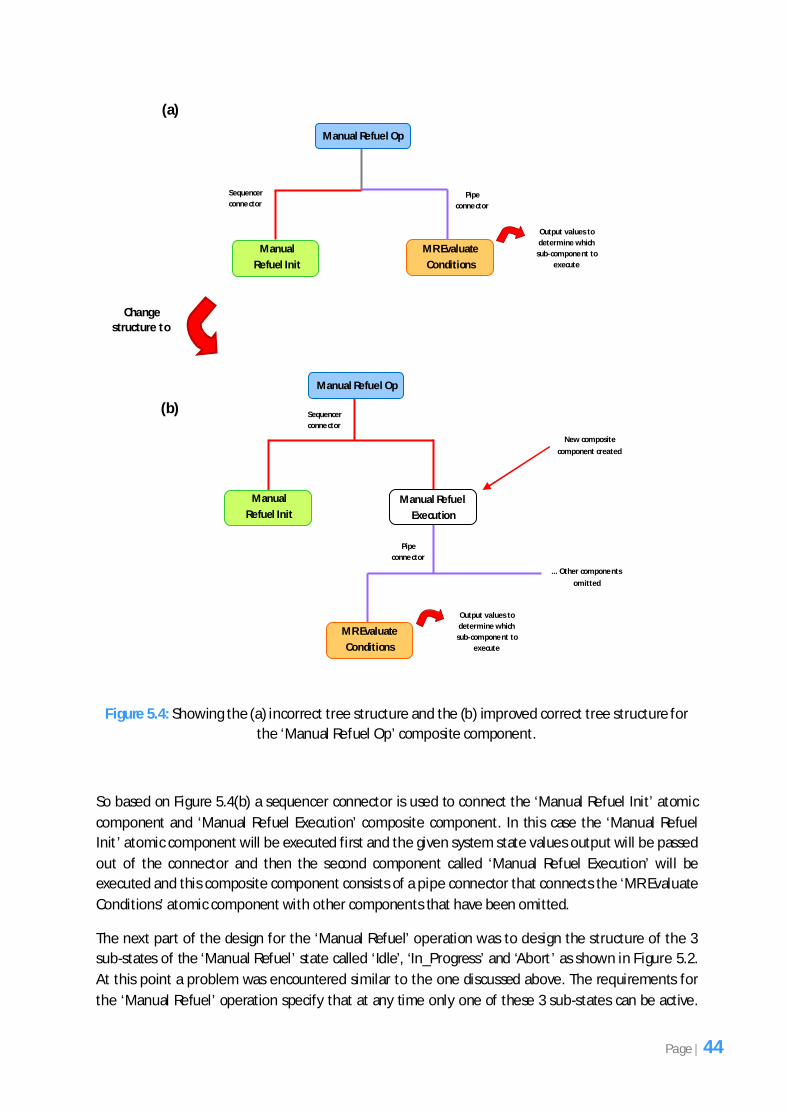
Figure 5.4(a) shows what the hierarchical tree structure would look like if both the ‘Manual Refuel
Init’ atomic component and the ‘MR Evaluate Conditions’ atomic component were represented at
the same level. Notice the conflict of the connectors where the ‘Manual Refuel Init’ atomic
component requires a sequencer connector but the ‘MR Evaluate Conditions’ atomic component
requires a pipe connector. Based on the rules of the exogenous connectors’ component model, you
cannot have more than one exogenous connector on the same level and so the structure had to be
changed to conform to the rules of this component model and this corrected structure is shown in
Figure 5.4(b). Notice how in Figure 5.4(b) the conflicting connectors’ problem has now been resolved
by adding a new composite component called ‘Manual Refuel Execution’ which now contains the
‘MR Evaluate Conditions’ atomic component and this composite component now uses a pipe
connector to connect to this atomic component. So the exogenous connectors have been separated
and only one exists on each level making the structure valid.
Page | 43
Figure 5.4: Showing the (a) incorrect tree structure and the (b) improved correct tree structure for
the ‘Manual Refuel Op’ composite component.
So based on Figure 5.4(b) a sequencer connector is used to connect the ‘Manual Refuel Init’ atomic
component and ‘Manual Refuel Execution’ composite component. In this case the ‘Manual Refuel
Init’ atomic component will be executed first and the given system state values output will be passed
out of the connector and then the second component called ‘Manual Refuel Execution’ will be
executed and this composite component consists of a pipe connector that connects the ‘MR Evaluate
Conditions’ atomic component with other components that have been omitted.
The next part of the design for the ‘Manual Refuel’ operation was to design the structure of the 3
sub-states of the ‘Manual Refuel’ state called ‘Idle’, ‘In_Progress’ and ‘Abort’ as shown in Figure 5.2.
At this point a problem was encountered similar to the one discussed above. The requirements for
the ‘Manual Refuel’ operation specify that at any time only one of these 3 sub-states can be active.
Manual Refuel Op
MR Evaluate
Conditions
Sequencer
conne ctor
Manual
Refuel Init
Pipe
conne ctor
Output values to
determine which
sub-compone nt to
execute
Manual Refuel Op
MR Evaluate
Conditions
Sequencer
conne ctor
Manual
Refuel Init
Pipe
conne ctor
Output values to
determine which
sub-compone nt to
execute
Manual Refuel
Execution
Change structure to
... Other compone nts
omitted
(a)
(b)
New composite
component created
Page | 44
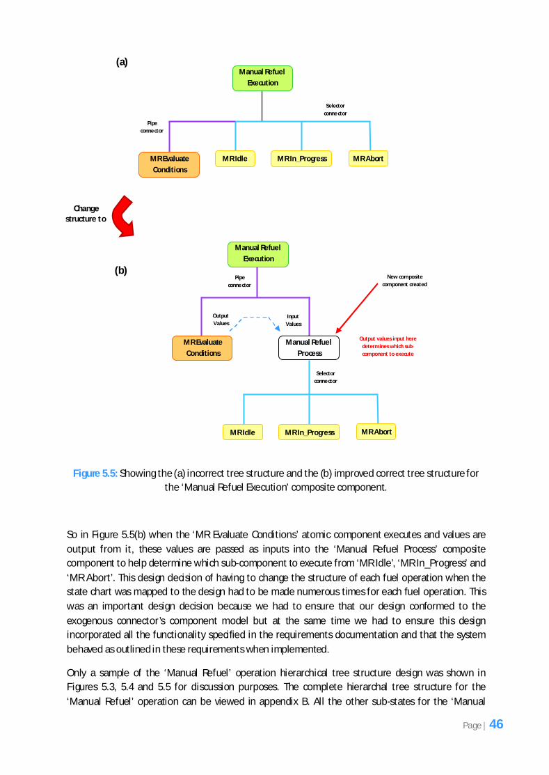
So it was clear that a selector connector would be most appropriate to use here however there
would be a conflict of representing these 3 sub-states as components in the hierarchical tree
structure since these 3 sub-states appear in the same state as the ‘Evaluate_Conditions’ method in
Figure 5.2. Figure 5.5(a) shows this conflict when these states are mapped as components in the
hierarchical tree structure. Notice how the ‘MR Evaluate Conditions’ atomic component requires a
pipe connector, since it outputs some values, however the ‘MR Idle’, ‘MR In_Progress’ and ‘MR
Abort’ components (which correspond to the sub-states ‘Idle’, ‘In_Progress’ and ‘Abort’ in Figure 5.2)
require a selector connector. Thus, representing the structure as shown in Figure 5.5(a) would be
invalid and so it had to be modified to reflect the rules of the exogenous connectors’ component
model which is shown in Figure 5.5(b). So now a new composite component called ‘Manual Refuel
Process’ was created at the same level as the ‘MR Evaluate Conditions’ atomic component which
would contain the selector connector along with the 3 sub-components. Notice how the conflicting
connectors problem has now been resolved by creating this new composite component called
‘Manual Refuel Process’. Note that the higher level components shown in Figure 5.4 have been
omitted in Figure 5.5 to simplify understanding since the focus here is now on the ‘Manual Refuel
Execution’ composite component.
You will notice that the ‘Evaluate_Conditions’ method in Figure 5.2 has been represented as an
atomic component called ‘MR Evaluate Conditions’ in the design. Again, due to the way the
exogenous connectors’ component model has been developed, we had to represent this as an
atomic component. The actual computation code that evaluates the conditions is written inside the
computation unit (which is located inside the atomic component). This will be discussed more in later
sections.
Page | 45
Figure 5.5: Showing the (a) incorrect tree structure and the (b) improved correct tree structure for
the ‘Manual Refuel Execution’ composite component.
So in Figure 5.5(b) when the ‘MR Evaluate Conditions’ atomic component executes and values are
output from it, these values are passed as inputs into the ‘Manual Refuel Process’ composite
component to help determine which sub-component to execute from ‘MR Idle’, ‘MR In_Progress’ and
‘MR Abort’. This design decision of having to change the structure of each fuel operation when the
state chart was mapped to the design had to be made numerous times for each fuel operation. This
was an important design decision because we had to ensure that our design conformed to the
exogenous connector’s component model but at the same time we had to ensure this design
incorporated all the functionality specified in the requirements documentation and that the system
behaved as outlined in these requirements when implemented.
Only a sample of the ‘Manual Refuel’ operation hierarchical tree structure design was shown in
Figures 5.3, 5.4 and 5.5 for discussion purposes. The complete hierarchal tree structure for the
‘Manual Refuel’ operation can be viewed in appendix B. All the other sub-states for the ‘Manual
Pipe
conne ctor
Selector
conne ctor
Manual Refuel
Process
Manual Refuel
Execution
MR Evaluate
Conditions
MR Idle MR In_Progress MR Abort
Pipe
conne ctor
Selector
conne ctor
Change structure to
Manual Refuel
Execution
MR Evaluate
Conditions
MR Idle MR In_Progress MR Abort
Output
Values
Input
Values
Output values input here
determines which sub-
component to execute
(a)
(b) New composite
component created
Page | 46
Refuel’ operation do not require further discussion since the design decisions made were very similar
to the ones discussed above.
Designing each fuel operation was an iterative process. We first had to consider which components
had to exist at a given level and then an appropriate exogenous connector had to be selected which
would connect these components together. If multiple connectors were required at the same level
mainly because one component required the use of one connector while the other required the use
of another, then the components had to be separated so that they were not on the same level as
described above with the ‘Manual Refuel Init’ atomic component and the ‘MR Evaluate Conditions’
atomic component. In the state charts requirements documentation, both these exist in the same
state (‘Manual Refuel’) in Figure 5.2. However, when it came to mapping them using the exogenous
connectors’ component model to create our hierarchical tree structure design, the ‘Manual Refuel
Init’ atomic component and the ‘MR Evaluate Conditions’ atomic component could not be
represented on the same level because they both required a different exogenous connector and due
to the rules of the exogenous connectors’ component model this is not allowed. Hence the reasons
for separating them onto different levels in the hierarchical tree structure design as shown in Figure
5.4(b).
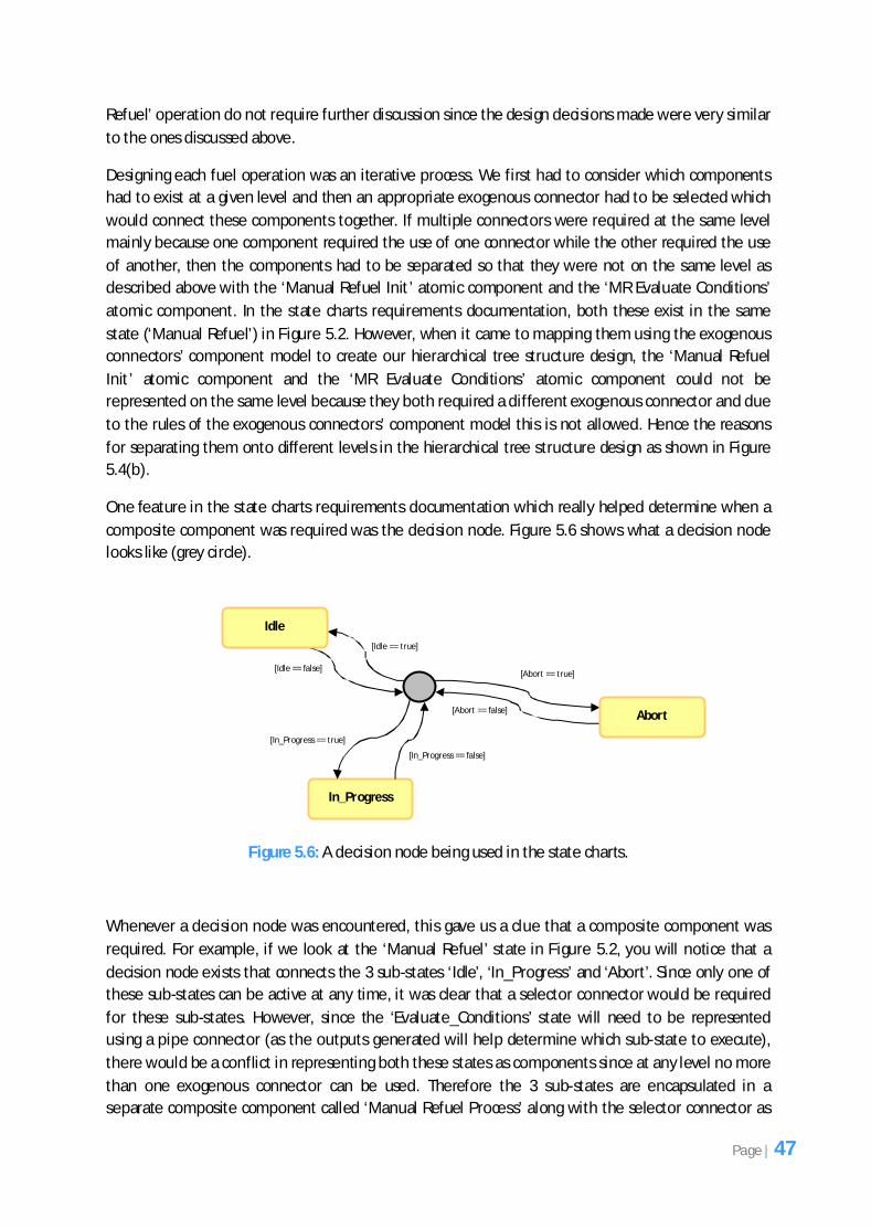
One feature in the state charts requirements documentation which really helped determine when a
composite component was required was the decision node. Figure 5.6 shows what a decision node
looks like (grey circle).
Figure 5.6: A decision node being used in the state charts.
Whenever a decision node was encountered, this gave us a clue that a composite component was
required. For example, if we look at the ‘Manual Refuel’ state in Figure 5.2, you will notice that a
decision node exists that connects the 3 sub-states ‘Idle’, ‘In_Progress’ and ‘Abort’. Since only one of
these sub-states can be active at any time, it was clear that a selector connector would be required
for these sub-states. However, since the ‘Evaluate_Conditions’ state will need to be represented
using a pipe connector (as the outputs generated will help determine which sub-state to execute),
there would be a conflict in representing both these states as components since at any level no more
than one exogenous connector can be used. Therefore the 3 sub-states are encapsulated in a
separate composite component called ‘Manual Refuel Process’ along with the selector connector as
In_Progress
[Idle == true]
Idle
[Idle == false]
[In_Progress == false]
[In_Progress == true]
Abort
[Abort == true]
[Abort == false]
Page | 47
can be seen in Figure 5.5(b) and this composite component can now be represented at the same
level as the ‘MR Evaluate Conditions’ atomic component connected by a pipe connector. The decision
nodes helped speed up the design process and also made the mapping process much simpler.
All the fuel operations were designed similarly in terms of representing them as a hierarchical tree
structure and the design decisions made at each stage were similar to those discussed above
therefore for this reason the rest of the designs will not be discussed however the full hierarchical
tree structure designs for all the fuel operations can be viewed in appendix B.
5.3 The Need for a New Connector
During the process of designing the hierarchical tree structures for each fuel operation, it became
apparent that when attempting to map certain state charts in the requirements documentation, the
3 exogenous connectors did not meet our needs entirely in some cases. For example, when we
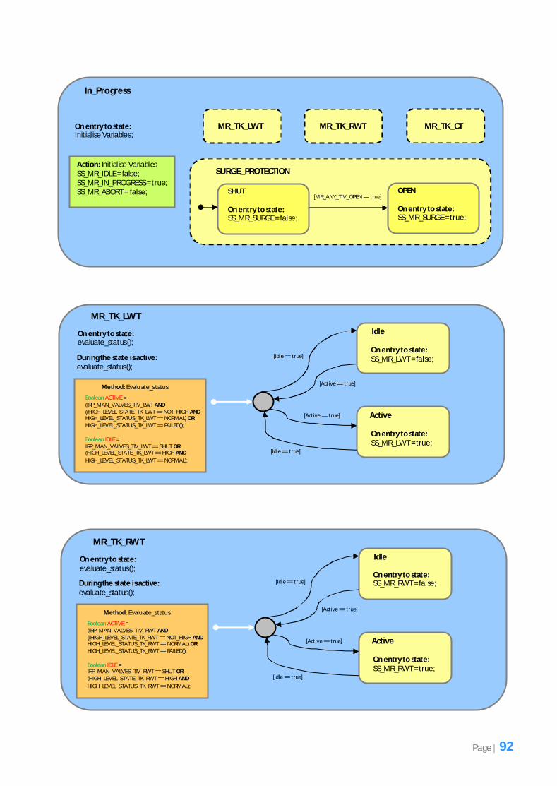
attempted to map the ‘In_Progress’ state chart shown in Figure 5.7 (which is actually a sub-state of
the ‘Manual Refuel’ state in Figure 5.2), we noticed that multiple states could be active at the same
time. The dotted lines around the state boxes indicate that multiple states can execute concurrently.
The problem was that the exogenous connectors’ component model we did not offer this type of
connector. The connector which closely resembled it was the sequencer connector since it could be
used to execute the states in order and eventually all the states would be executed, although not
concurrently.
Figure 5.7: Showing the sub-states that can be executed concurrently for the ‘In_Progress’ state
chart.
Therefore during design we thought that it might be a good idea to design this type of connector
however due to the limited development time it could not be implemented. The name given to this
type of connector was ‘Concurrent connector’. This connector would allow multiple components to
be executed at the same time and could be added to the future work for the project.
Page | 48
It is important to note that this concurrent connector was not used for the implementation of this
fuel management system since it was not fully designed and implemented. It was only mentioned
here since the need arose for another type of connector when faced with a situation where multiple
components can execute concurrently like in Figure 5.7. So in place of where the ‘Concurrent
connector’ could have been used we felt that the sequencer connector was sufficient since all the
components would get executed regardless, although not concurrently.
5.4 Mapping the Variables in the State Charts to the Design
Once each fuel operation was designed in a hierarchical tree structure manner the next step was to
map the variables shown in the state charts requirements documentation. A unique feature of the
exogenous connectors’ component model is that no global variables can exist. A global variable is a
variable that is accessible in every scope [19]. Therefore the only way a variable can be used in the
exogenous connectors’ component model is if it is passed as a parameter to a method. If you recall
the class diagram representation of the exogenous connectors’ component model in Figure 3.5 of
Chapter 3, you will see that the ‘Method’ class has 2 parameters: input (‘Inparam’ class) and output
(‘Outparam’ class) parameters. This is the only mechanism by which variables can be passed to the
component’s methods and since our design must conform to the exogenous connectors’ component
model we had to make sure that the variables in the state charts were mapped in accordance to
these rules. However, the problem was that the diagrammatic state chart requirements
documentation used global variables in all the fuel operations and therefore we had to ensure that
during mapping these global variables were represented as input and output parameters.
Before the variables could be mapped to the design, all the variables in the state chart requirements
documentation for a given fuel operation had to be identified. All the variables that are used
throughout each fuel operation state chart are located in the ‘Evaluate_Conditions’ method. In
addition to this the system state variables shown in the ‘Idle’ and ‘Abort’ sub-states in Figure 5.2 are
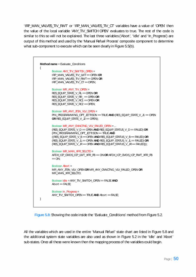
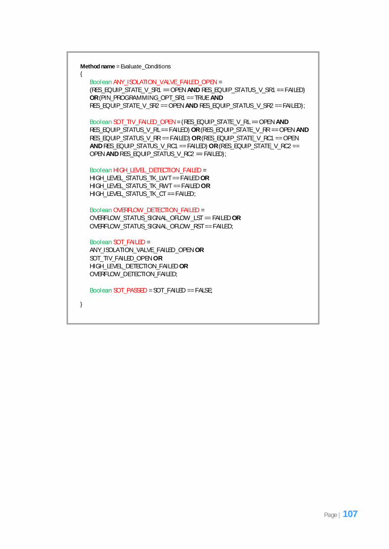
also used. Figure 5.8 shows the contents of the ‘Evaluate_Conditions’ method for the ‘Manual
Refuel’ state chart from Figure 5.2. It shows the code that deals with evaluating the conditions. The
‘Evaluate_Conditions’ method in Figure 5.8 has been modified slightly to preserve the privacy of
Airbus’s data.
You will notice that the code written inside the ‘Evaluate_Conditions’ method is not language specific
and so can essentially be classed as pseudocode6. The code inside the method will be briefly
discussed so that its purpose is clear. As mentioned earlier the purpose of the ‘Evaluate_Conditions’
method is to carry out some computations on some variables and determine which sub-state to
execute based on the value of the variables. The ‘Evaluate_Conditions’ method is present in all the
fuel operations at the top most level states. Notice that the structure of the method is similar to any
method written in any programming language. All the local variable names have been highlighted in
red and they all have a boolean type. If we look at the code for the first local variable called
‘ANY_TIV_SWITCH OPEN’ you will notice that if the ‘IRP_MAN_VALVES_TIV_LWT’ or
6 A high level description of a computer programming algorithm which uses conventions similar to a programming language but is intended
to be read by a human rather than a machine [19].
Page | 49
‘IRP_MAN_VALVES_TIV_RWT’ or ‘IRP_MAN_VALVES_TIV_CT’ variables have a value of ‘OPEN’ then
the value of the local variable ‘ANY_TIV_SWITCH OPEN’ evaluates to true. The rest of the code is
similar to this so will not be explained. The last three variables (‘Abort’, ‘Idle’ and ‘In_Progress’) are
output of this method and used by the ‘Manual Refuel Process’ composite component to determine
what sub-component to execute which can be seen clearly in Figure 5.5(b).
Figure 5.8: Showing the code inside the ‘Evaluate_Conditions’ method from Figure 5.2.
All the variables which are used in the entire ‘Manual Refuel’ state chart are listed in Figure 5.8 and
the additional system state variables are also used as shown in Figure 5.2 in the ‘Idle’ and ‘Abort’
sub-states. Once all these were known then the mapping process of the variables could begin.
Method name = Evaluate_Conditions {
Boolean ANY_TIV_SWITCH_OPEN = IRP_MAN_VALVES_TIV_LWT == OPEN OR IRP_MAN_VALVES_TIV_RWT == OPEN OR IRP_MAN_VALVES_TIV_CT == OPEN;
Boolean MR_ANY_TIV_OPEN = RES_EQUIP_STATE_V_RL == OPEN OR RES_EQUIP_STATE_V_RR_ == OPEN OR RES_EQUIP_STATE_V_RC1 == OPEN OR RES_EQUIP_STATE_V_RC2 == OPEN;
Boolean MR_ANY_JTSN_VLV_OPEN = PIN_PROGRAMMING_OPT_JETTISON == TRUE AND (RES_EQUIP_STATE_V_J1 == OPEN OR RES_EQUIP_STATE_V_J2 == OPEN);
Boolean MR_ANY_CNNCTNG_VLV_FAILED_OPEN = ... (RES_EQUIP_STATE_V_D == OPEN AND RES_EQUIP_STATUS_V_D == FAILED) OR (PIN_PROGRAMMING_OPT_JETTISON == TRUE AND ((RES_EQUIP_STATE_V_B == OPEN AND RES_EQUIP_STATUS_V_B == FAILED) OR (RES_EQUIP_STATE_V_JL == OPEN AND RES_EQUIP_STATUS_V_JL == FAILED) OR (RES_EQUIP_STATE_V_JR == OPEN AND RES_EQUIP_STATUS_V_JR == FAILED)));
Boolean MR_MAN_XFR_SELCTD = AFDX_ICP_CMDS_ICP_LWT_XFR_PB == ON OR AFDX_ICP_CMDS_ICP_RWT_XFR_PB == ON;
Boolean Abort = MR_ANY_JTSN_VLV_OPEN OR MR_ANY_CNNCTNG_VLV_FAILED_OPEN OR MR_MAN_XFR_SELCTD;
Boolean Idle = ANY_TIV_SWITCH_OPEN == FALSE AND Abort == FALSE;
Boolean In_Progress = ANY_TIV_SWITCH_OPEN == TRUE AND Abort == FALSE;
}
Page | 50
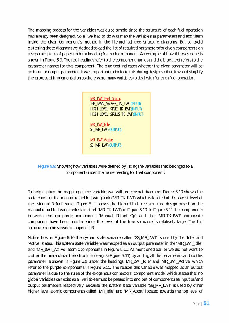
The mapping process for the variables was quite simple since the structure of each fuel operation
had already been designed. So all we had to do was map the variables as parameters and add them
inside the given component’s method in the hierarchical tree structure diagrams. But to avoid
cluttering these diagrams we decided to add the list of required parameters for given components on
a separate piece of paper under a heading for each component. An example of how this was done is
shown in Figure 5.9. The red headings refer to the component names and the black text refers to the
parameter names for that component. The blue text indicates whether the given parameter will be
an input or output parameter. It was important to indicate this during design so that it would simplify
the process of implementation as there were many variables to deal with for each fuel operation.
Figure 5.9: Showing how variables were defined by listing the variables that belonged to a
component under the name heading for that component.
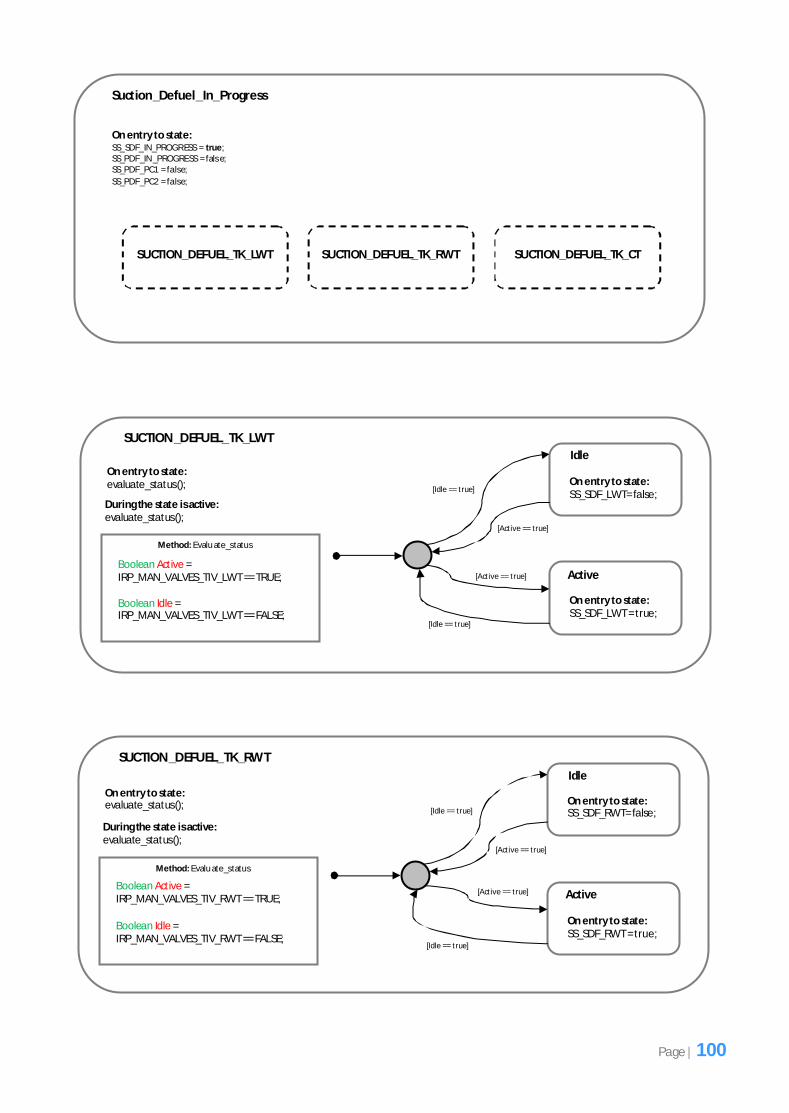
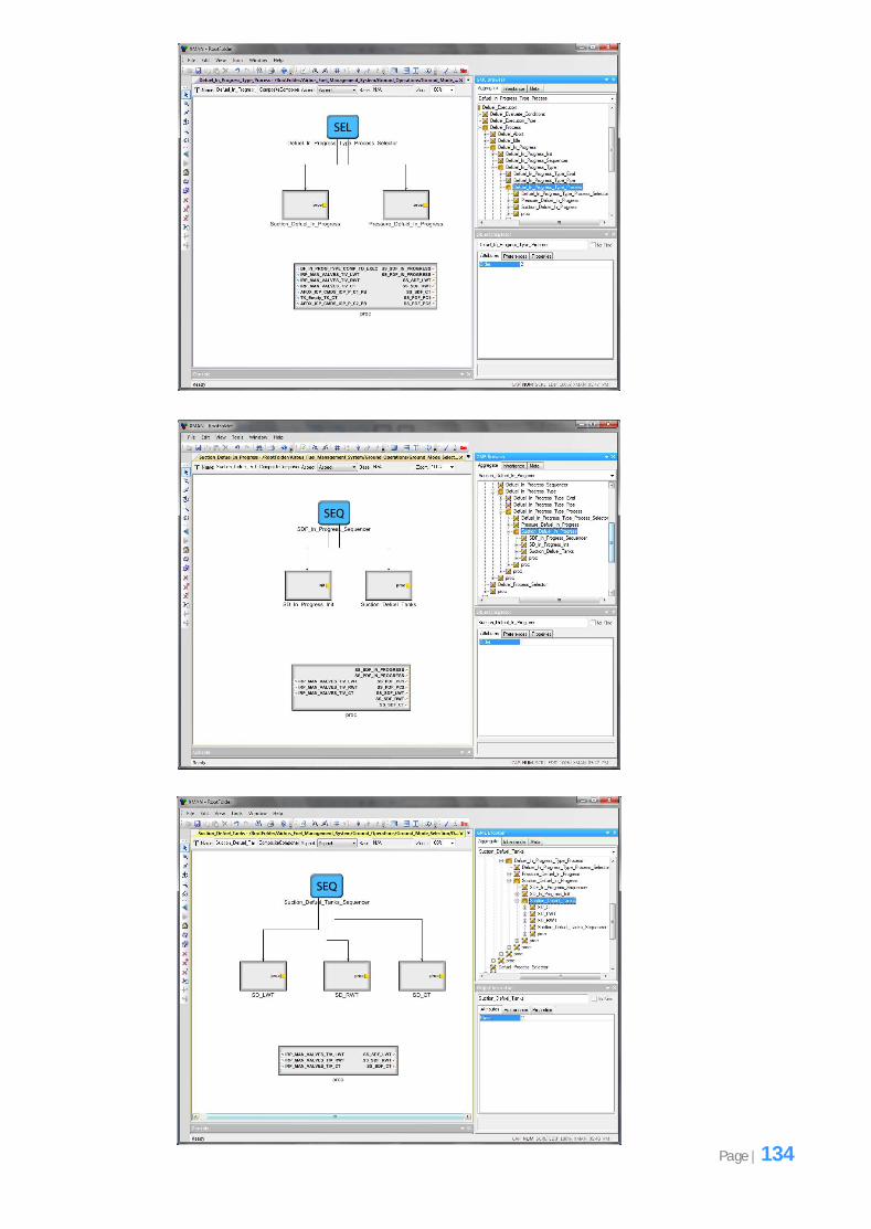
To help explain the mapping of the variables we will use several diagrams. Figure 5.10 shows the
state chart for the manual refuel left wing tank (MR_TK_LWT) which is located at the lowest level of
the ‘Manual Refuel’ state. Figure 5.11 shows the hierarchical tree structure design based on the
manual refuel left wing tank state chart (MR_TK_LWT) in Figure 5.10. In Figure 5.11 the components
between the composite component ‘Manual Refuel Op’ and the ‘MR_TK_LWT’ composite
component have been omitted since the level of the tree structure is relatively large. The full
structure can be viewed in appendix B.
Notice how in Figure 5.10 the system state variable called ‘SS_MR_LWT’ is used by the ‘Idle’ and
‘Active’ states. This system state variable was mapped as an output parameter in the ‘MR_LWT_Idle’
and ‘MR_LWT_Active’ atomic components in Figure 5.11. As mentioned earlier we did not want to
clutter the hierarchical tree structure designs (Figure 5.11) by adding all the parameters and so this
parameter is shown in Figure 5.9 under the headings ‘MR_LWT_Idle’ and ‘MR_LWT_Active’ which
refer to the purple components in Figure 5.11. The reason this variable was mapped as an output
parameter is due to the rules of the exogenous connectors’ component model which states that no
global variables can exist as all variables must be passed into and out of components as input or/and
output parameters respectively. Because the system state variable ‘SS_MR_LWT’ is used by other
higher level atomic components called ‘MR_Idle’ and ‘MR_Abort’ located towards the top level of
the hierarchical tree structure, as can be seen in the corresponding state chart in Figure 5.2, it had to
be specified as an output parameter so that it could be passed all the way up. Therefore, once this
variable has been set by either the ‘MR_LWT_Idle’ or ‘MR_LWT_Active’ atomic components it will
need to be output so that other components can use it in case they need to reset the variable. Recall
that each fuel operation can execute multiple times in an iterative manner because as the
‘Evaluate_Conditions’ method is computed, a different component may need to be executed.
Figure 5.10: Manual Refuel Left Wing Tank (MR_TK_LWT) state chart from the diagrammatic state
chart requirements.
Figure 5.11: Hierarchical tree structure design based on the Manual Refuel Left Wing Tank
(MR_TK_LWT) state chart in Figure 5.10.
Manual Refuel Op
.
. Other components
omitted . .
MR_LWT_Eval_Status MR_LWT_Process
MR_LWT_Idle MR_LWT_Active
MR_TK_LWT
Page | 52
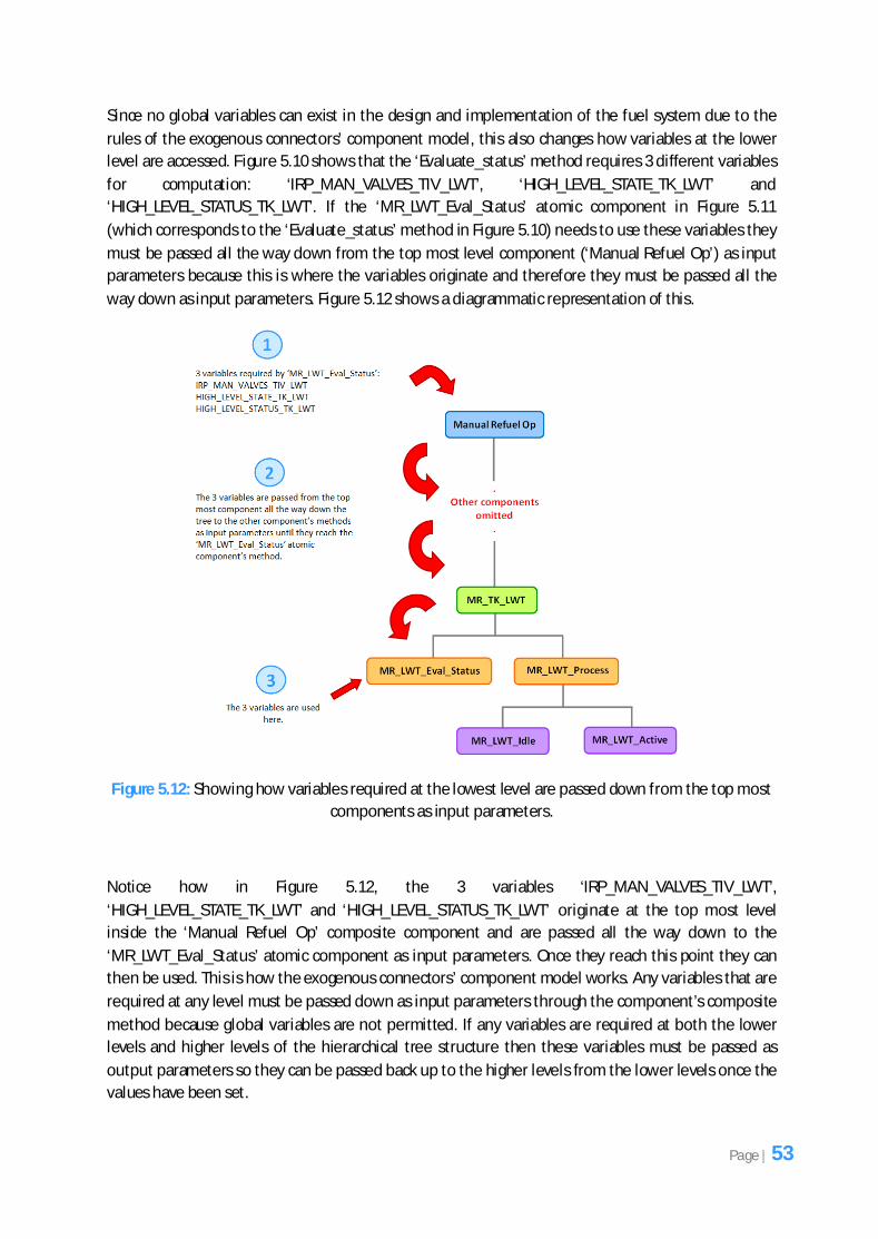
Since no global variables can exist in the design and implementation of the fuel system due to the
rules of the exogenous connectors’ component model, this also changes how variables at the lower
level are accessed. Figure 5.10 shows that the ‘Evaluate_status’ method requires 3 different variables
for computation: ‘IRP_MAN_VALVES_TIV_LWT’, ‘HIGH_LEVEL_STATE_TK_LWT’ and
‘HIGH_LEVEL_STATUS_TK_LWT’. If the ‘MR_LWT_Eval_Status’ atomic component in Figure 5.11
(which corresponds to the ‘Evaluate_status’ method in Figure 5.10) needs to use these variables they
must be passed all the way down from the top most level component (‘Manual Refuel Op’) as input
parameters because this is where the variables originate and therefore they must be passed all the
way down as input parameters. Figure 5.12 shows a diagrammatic representation of this.
Figure 5.12: Showing how variables required at the lowest level are passed down from the top most
components as input parameters.
Notice how in Figure 5.12, the 3 variables ‘IRP_MAN_VALVES_TIV_LWT’,
‘HIGH_LEVEL_STATE_TK_LWT’ and ‘HIGH_LEVEL_STATUS_TK_LWT’ originate at the top most level
inside the ‘Manual Refuel Op’ composite component and are passed all the way down to the
‘MR_LWT_Eval_Status’ atomic component as input parameters. Once they reach this point they can
then be used. This is how the exogenous connectors’ component model works. Any variables that are
required at any level must be passed down as input parameters through the component’s composite
method because global variables are not permitted. If any variables are required at both the lower
levels and higher levels of the hierarchical tree structure then these variables must be passed as
output parameters so they can be passed back up to the higher levels from the lower levels once the
values have been set.
Page | 53
The implementation phase involved converting the hierarchical tree structure designs created for all
the 6 fuel operations during the design phase into a working software artefact using the Generic
Modelling Environment (GME) toolkit. This chapter focuses on the important aspects of the fuel
management system implementation.
6.1 Technology Choices
Appropriate software tools were required to aid the development of the fuel management system.
This involved using certain modelling and programming languages that were suitable for avionics
software development. This section discusses the tools that were selected.
6.1.1 Modelling Language Choice
There were various modelling languages on the market that could have been selected for the
implementation of the fuel management system, however GME was specifically chosen since it is a
recommended modelling environment in the avionics industry and since this project involves
implementing a piece of avionics software, specifically a fuel management system, it seemed more
appropriate to use GME as the primary modelling language.
Another modelling language that was considered is EMF (Eclipse Modelling Framework). EMF is
similar to GME in that it is a modelling framework that allows you to develop software based on a
structured model [20]. However, the difference between the two modelling languages is that GME is
based on the C++ programming language where as EMF is based on the Java programming language.
Since our experience in programming mainly lies entirely in Java, EMF was an attractive modelling
language to begin with, however a majority of safety-critical software is programmed in C or C++ and
since the fuel management system is itself a safety-critical piece of software, it was important to use
a modelling language that was suitable for the given domain. Therefore it was decided that GME
would be the most suitable modelling language for this project.
Fuel Management System Implementation
Chapter 6
Page | 54
6.1.2 Programming Language Choice
The main programming language that had to be selected was C++ since the tool that was supplied to
us by the School of Computer Science (composed of the exogenous connectors’ component model
and the interpreter) was written in the C++ programming language and GME itself is based on C++.
Therefore we had to gain a good understanding of C++ in order to first understand the tool and then
implement our fuel management system in GME. However, the programming language C was learnt
first since around 80% of C++ is based on C and therefore acquiring this knowledge beforehand was
essential. Although this meant that additional time had to be invested in learning entirely new
programming languages (C and C++), this was considered more of an exciting challenge for us rather
than a drawback. Learning new languages would be motivational since it would broaden our
programming skills and knowledge and this is especially beneficial in industry.
6.2 Implementation Discussion
The fuel management system was developed in an incremental manner. First the entire structure of
each fuel operation was implemented in GME based on the hierarchical tree structure designs in a
top-down manner and the necessary variables were added as parameters in the component’s
methods in a bottom-up manner. The reason for adding the parameters in a bottom-up manner
were because the data is passed via parameters and so each component had to be tested once it
was implemented using the simulator (which is part of the tool) to ensure that the implementation
was valid and conformed to the exogenous connectors’ component model. Finally the code for each
computation unit (located in every atomic component) was written using C++. This section focuses
on the important and interesting aspects of the system’s implementation.
6.2.1 Implementing the Fuel Management System Using the Tool
The fuel management system was implemented in GME using the tool that was supplied to us by the
School of Computer Science. This tool was composed of the exogenous connectors’ component
model, which was used to create the implementation of the system, and an interpreter, which was
used to interpret the implementation of the fuel management system in GME.
This tool played an important role in development since our implementation had to conform to the
exogenous connectors’ component model. When implementing the fuel management system in GME
we used the hierarchical tree structure designs created during the design phase.
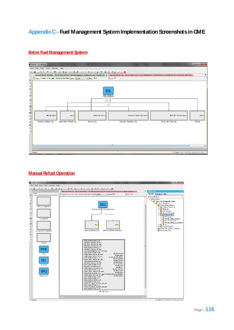
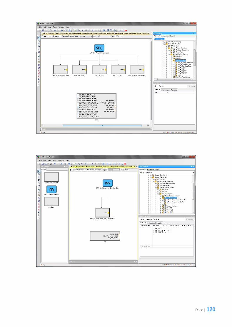
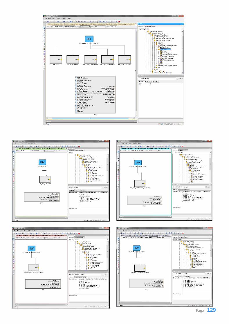
Figure 6.1 shows the implementation of the ‘Manual Refuel Process’ composite component in the
GME toolkit. When defining the structure of this composite component we used the elements
located on the left hand side of the GME toolkit as can be seen in Figure 6.1. These elements belong
to the exogenous connectors’ component model and were used to implement the entire fuel
management system by dragging and dropping them onto the development area. The steps
undertaken in developing the system in GME were similar for all the fuel operations. We first added
the necessary exogenous connector followed by the sub-components (atomic and/or composite) and
then all these components were connected to the given exogenous connector. The exogenous
connector and all the sub-components were given appropriate names based on the names given in
Page | 55
the hierarchical tree structure designs. The next stage involved defining the composite method
(‘proc’ composite method in Figure 6.1) inside the composite components and for the atomic
components a method, invocation connector and a computation unit was defined. Once the entire
fuel operation structure was complete the input and output parameters (as shown inside the ‘Proc’
composite method in Figure 6.1) were added to the methods in a bottom-up manner which will be
discussed clearly in later sections. Finally the C++ code was written inside all the computation units
for each fuel operation.
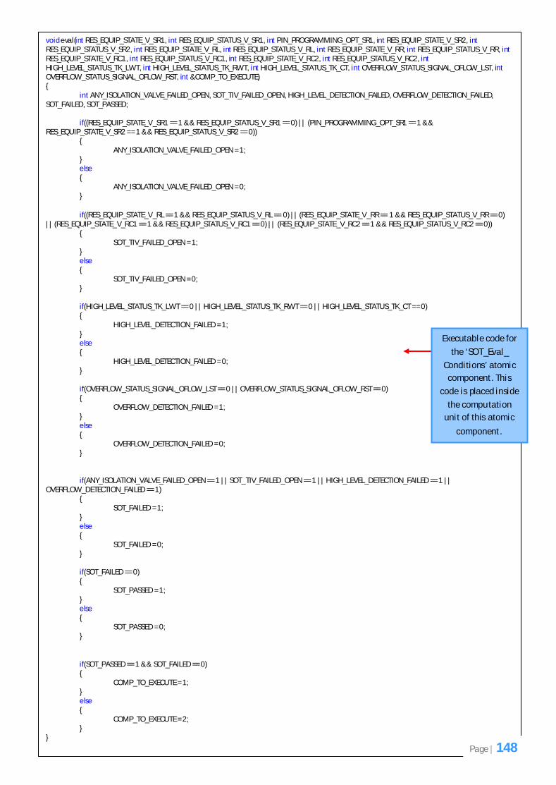
Figure 6.1: Showing the implementation of the ‘Manual Refuel Process’ composite component in the
GME toolkit.
The interpreter was used to process the implementation of the fuel operations in GME. At each point
as we developed the lower level components of the fuel operation, we used the interpreter to
process the components to check that the implementation was valid and that it conformed to the
exogenous connectors’ component model. Figure 6.1 shows the interpreter button in the GME
toolkit. When this button is clicked a simulator GUI appears (Figure 6.2) which allows you to supply
some input values for the input parameters that were defined for the composite methods of the
components. Once the interpreter has executed and processed the implementation in GME some
output values are generated. The output values depend on the values supplied as inputs. The values
output refer to the system state variables which indicate which system state variable is currently true
(1) or false (0). For example if the system state variable ‘SS_MR_LWT’ is output with a value of 1, this
means that the left wing tank sub-component was executed to allow manual refuelling of the left
wing tank. The simulator is discussed in more detail in the next chapter during testing.
Elements of the
exogenous
connectors’
component
model used to
implement the
fuel
management
system.
The interpreter
button used to
process the
implementation
in GME.
Page | 56
Figure 6.2: Showing the simulator GUI which appears when the interpreter button in GME is clicked.
It is important to note that the 2 parts that make up the tool (exogenous connectors’ component
model and the interpreter) go hand-in-hand. The exogenous connectors’ component model was used
to create the implementation of our fuel management system (recall that our objective was to use
this component model to implement such a system) and the interpreter was used to interpret the
implementation in GME based on the exogenous connectors’ component model.
GME is primarily a modelling language and so does not allow you to write code directly for each
element of the exogenous connectors’ component model except in computation units. This is why an
interpreter is required so that it can process the implementation in GME based on the exogenous
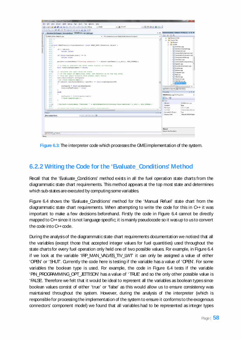
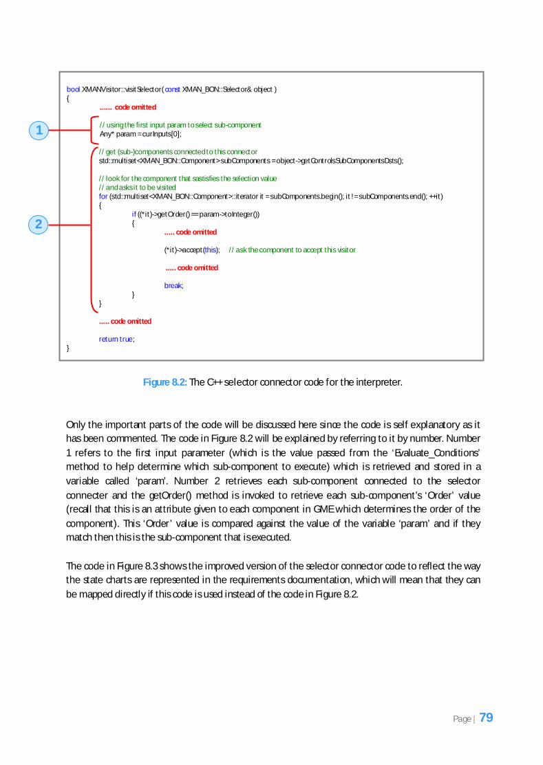
connectors’ component model. Figure 6.3 shows the code for the interpreter which was used. It was
developed by a colleague at the School of Computer Science in the Microsoft Visual Studio
environment. It currently shows a method that contains the code for the selector connector but this
is where the code for all the elements that appear in the exogenous connectors’ component model is
defined. Each time the interpreter button in Figure 6.1 is clicked the simulator in Figure 6.2 appears.
As soon as the input values have been supplied and the ‘Start’ button of the simulator is clicked the
code in Figure 6.3 (interpreter) is executed and it processes the implementation of the fuel
management system in GME. As the interpreter is executing and it encounters a particular element in
GME, such as a selector connector, this triggers a particular method to be executed inside the
interpreter depending on which element has been encountered. Each element in the exogenous
connectors’ component model has a corresponding method in the interpreter (Figure 6.3) which is
invoked each time the given element is encountered in GME. The code inside this method is
responsible for processing the given element in the exogenous connectors’ component model.
Page | 57
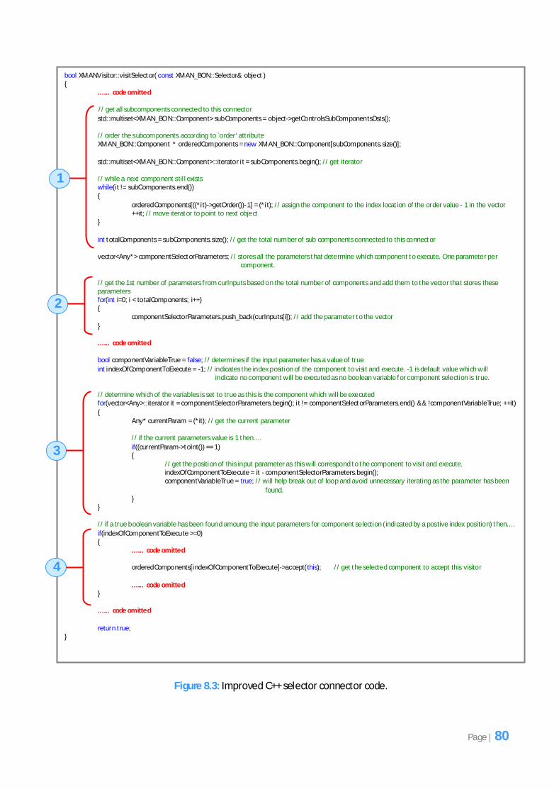
Figure 6.3: The interpreter code which processes the GME implementation of the system.
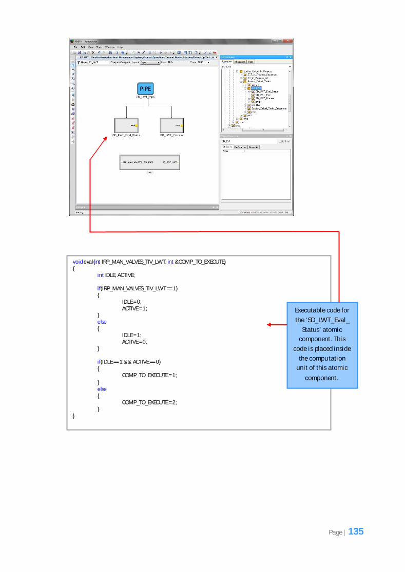
6.2.2 Writing the Code for the ‘Evaluate_Conditions’ Method
Recall that the ‘Evaluate_Conditions’ method exists in all the fuel operation state charts from the
diagrammatic state chart requirements. This method appears at the top most state and determines
which sub-states are executed by computing some variables.
Figure 6.4 shows the ‘Evaluate_Conditions’ method for the ‘Manual Refuel’ state chart from the
diagrammatic state chart requirements. When attempting to write the code for this in C++ it was
important to make a few decisions beforehand. Firstly the code in Figure 6.4 cannot be directly
mapped to C++ since it is not language specific; it is mainly pseudocode so it was up to us to convert
the code into C++ code.
During the analysis of the diagrammatic state chart requirements documentation we noticed that all
the variables (except those that accepted integer values for fuel quantities) used throughout the
state charts for every fuel operation only held one of two possible values. For example, in Figure 6.4
if we look at the variable ‘IRP_MAN_VALVES_TIV_LWT’ it can only be assigned a value of either
‘OPEN’ or ‘SHUT’. Currently the code here is testing if the variable has a value of ‘OPEN’. For some
variables the boolean type is used. For example, the code in Figure 6.4 tests if the variable
‘PIN_PROGRAMMING_OPT_JETTISON’ has a value of ‘TRUE’ and so the only other possible value is
‘FALSE’. Therefore we felt that it would be ideal to represent all the variables as boolean types since
boolean values consist of either ‘true’ or ‘false’ as this would allow us to ensure consistency was
maintained throughout the system. However, during the analysis of the interpreter (which is
responsible for processing the implementation of the system to ensure it conforms to the exogenous
connectors’ component model) we found that all variables had to be represented as integer types
Page | 58
(either with a value of 1 which represents true or a value of 0 which represents false) due to the
choice of the type made by the developers during the development of the tool. So we had to make
sure our implementation conformed to this. Therefore when attempting to indicate that a variable
will have a value of ‘true’ this was represented as 1 and a value of ‘false’ was represented as 0. Figure
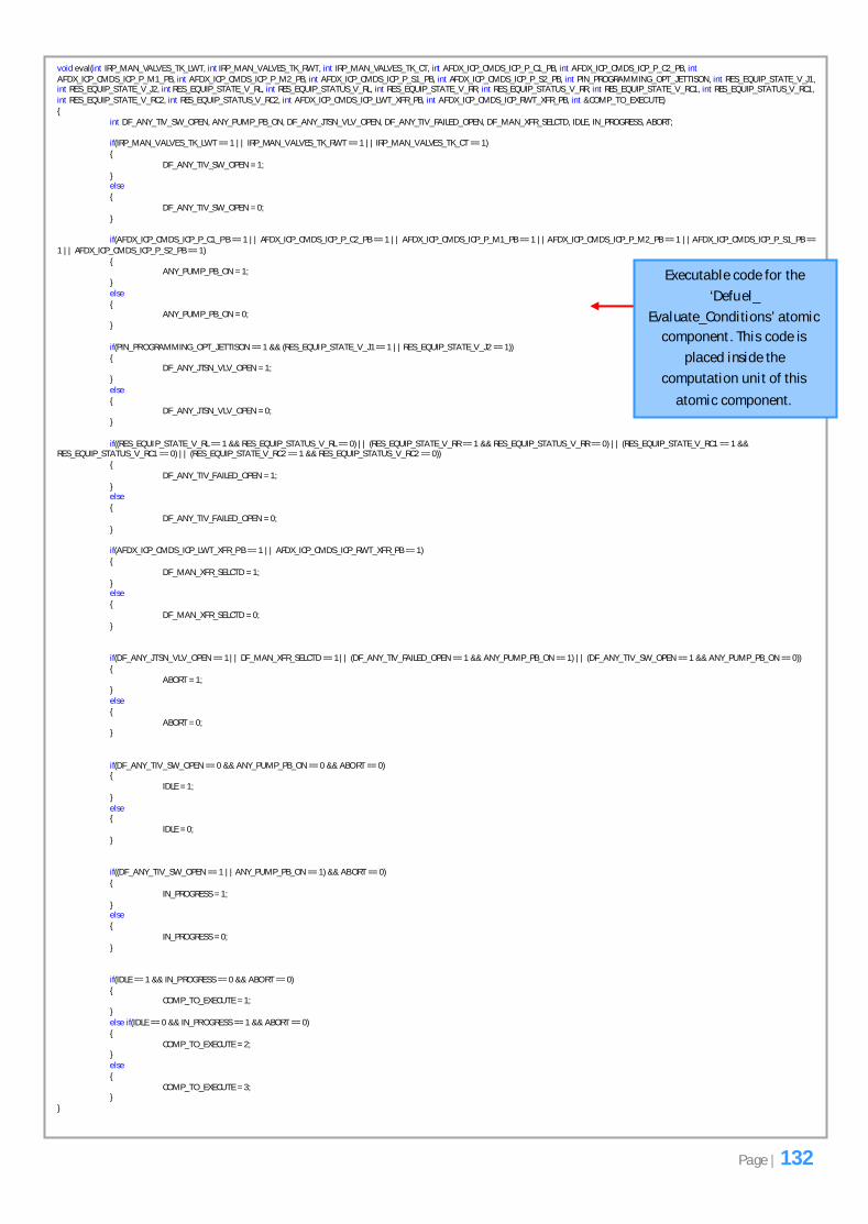
6.5 shows the C++ code that was written for the ‘Evaluate_Conditions’ method in Figure 6.4.
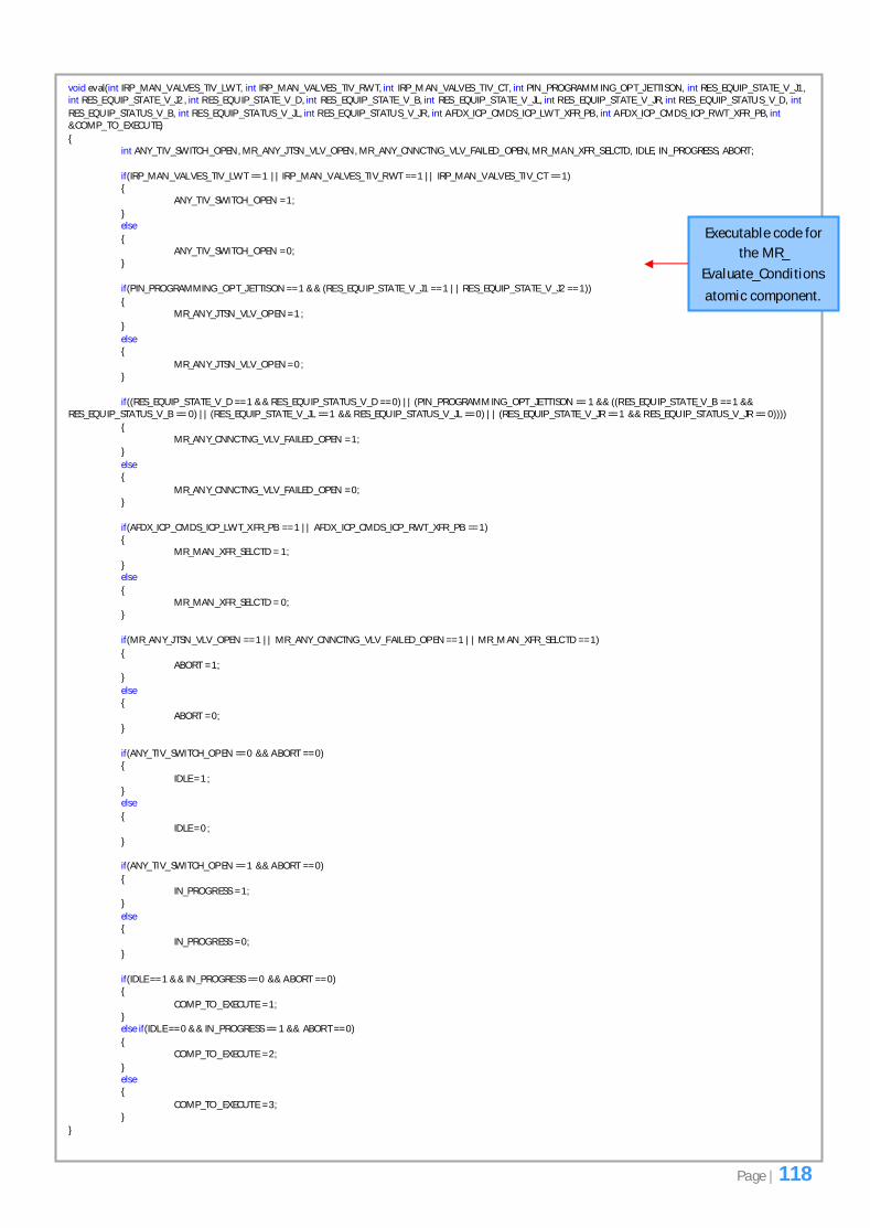
Figure 6.4: The ‘Evaluate_Conditions’ method for the ‘Manual Refuel’ state chart.
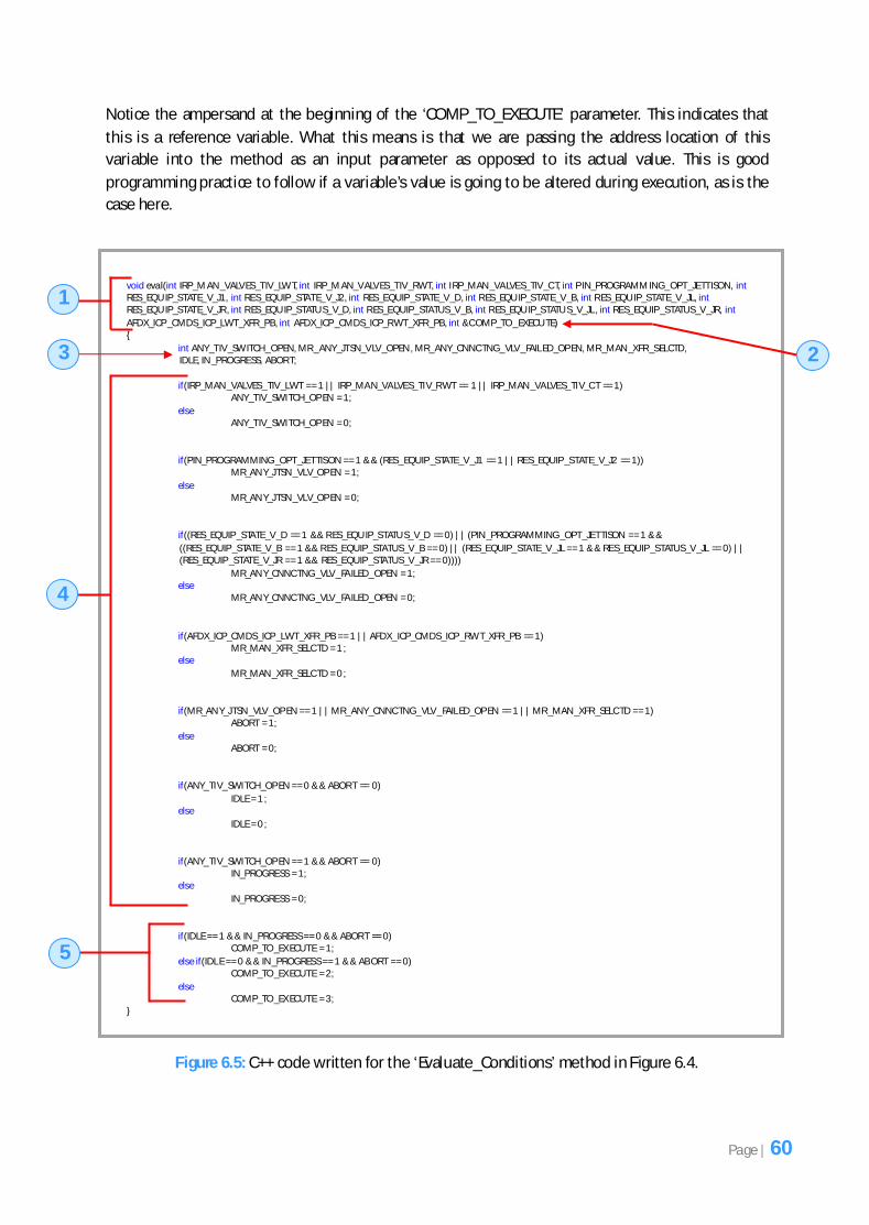
There are several important points to discuss for the code in Figure 6.5 and so we will refer to each
part of the code by number.
Number 1 refers to the method signature. Here we have named the method ‘eval’. As a convention
we decided that all the ‘Evaluate_Conditions’ methods would have the same name throughout the
implementation of the system. Notice the long list of input parameters that have been supplied here.
These are all the variables that are being used by the method in Figure 6.4 and if we recall one of the
rules of the exogenous connectors’ component model no global variables can exist and so all
variables had to be passed via input parameters to this method.
Number 2 refers to an additional parameter defined here called ‘COMP_TO_EXECUTE’ because recall
that the whole purpose of the ‘Evaluate_Conditions’ method is to compute some variables to
determine which sub-component to execute and this variable will hold the value of which
component to execute. This is explained more clearly when the code at number 5 is discussed.
Page | 59
Notice the ampersand at the beginning of the ‘COMP_TO_EXECUTE’ parameter. This indicates that
this is a reference variable. What this means is that we are passing the address location of this
variable into the method as an input parameter as opposed to its actual value. This is good
programming practice to follow if a variable’s value is going to be altered during execution, as is the
case here.
Figure 6.5: C++ code written for the ‘Evaluate_Conditions’ method in Figure 6.4.
void eval(int IRP_M AN _VALVES_TIV_LWT, int IRP_M AN_VALVES_TIV_RWT, int IRP_MAN _VALVES_TIV_C T, int P IN_PROGRAMM ING_OPT_JETTISON, int RES_EQU IP_STATE_V_J1, int RES_EQUIP _STATE_V_J2, int RES_EQUIP _STATE_V_D, int R ES_EQU IP_STATE_V_B, int R ES_EQU IP_STATE_V_JL, int RES_EQU IP_STATE_V_JR , int R ES_EQU IP_STATU S_V_D, int R ES_EQUIP_STATUS_V_B, int R ES_EQU IP_STATU S_V_JL , int RES_EQUIP _STATUS_V_JR, int
AFDX_ICP _CMDS_ICP_LWT_XFR _PB, int AFDX_ICP _CMDS_ICP_R WT_XFR _PB, int &C OMP_TO _EXECU TE) {
int ANY_TIV_SWITCH_OPEN, MR _ANY_JTSN_VLV_OPEN , MR_ANY_CNNC TNG_VLV_FAIL ED_OP EN, MR _MAN _XFR _SELCTD, IDLE, IN _PROGRESS, ABOR T;
if(IRP_MAN _VALVES_TIV_LWT == 1 || IRP_MAN_VALVES_TIV_R WT == 1 || IRP_MAN _VALVES_TIV_C T == 1) ANY_TIV_SWITCH_OP EN = 1;
if(ANY_TIV_SWITCH_OP EN == 1 && ABOR T == 0) IN_PROGRESS = 1; else
IN_PROGRESS = 0;
if(IDLE == 1 && IN _PROGRESS == 0 && ABOR T == 0) COMP_TO _EX ECUTE = 1;
else if(IDL E == 0 && IN _PROGRESS == 1 && AB ORT == 0) COMP_TO _EX ECUTE = 2;
else COMP_TO _EX ECUTE = 3; }
1
2 3
4
5
Page | 60
Number 3 refers to the local variables that have been defined which are exactly the same as those in
Figure 6.4 (variable names in red text). These local variables are set when the other variables passed
as input parameters are computed inside the ‘if-else’ blocks (Number 4).
Number 4 is where the computation of the variables that are passed as input parameters to the
method is performed. Notice how several ‘ if-else’ blocks are used here to determine the values of
the local variables. For example, the first ‘if ’ block in Figure 6.5 determines if the variables
‘IRP_MAN_VALVES_TIV_LWT’, ‘IRP_MAN_VALVES_TIV_RWT’ and ‘IRP_MAN_VALVES_TIV_CT’ have a
value of 1 (which corresponds to the value of ‘OPEN’ in Figure 6.4 for the first set of statements) and
if this is the case then the value of the local variable ‘ANY_TIV_SWITCH_OPEN’ is set to 1 to indicate
this is true else it is set to 0 to indicate this is false. It was also important to add ‘else’ blocks to the
code here to ensure that the value of the local variables had at least one value (either 1 or 0)
because these local variables are used towards the bottom of the code to determine the value of the
‘IDLE’, ‘IN_PROGRESS’ and ‘ABORT’ local variables. You will notice that we have represented the
values of the variables used in Figure 6.4 as integer values (either 1 for true or 0 for false) in the ‘if ’
statements in Figure 6.5. As mentioned earlier this was necessary since the interpreter was designed
to read only integer values. The rest of the ‘if’ statements are similar to the one discussed so do not
require further discussion.
Number 5 refers to new code that was added which is not present in the code in Figure 6.4. This code
determines which sub-component will be executed in the ‘Manual Refuel Process’ composite
component (Figure 6.6) by setting the value of the reference variable ‘COMP_TO_EXECUTE’ specified
in the method signature. The value of this reference variable is based on the values of the local
variables ‘IDLE’, ‘IN_PROGRESS’ and ‘ABORT’. If the value of the ‘IDLE’ local variable is 1 (which
represents true) and the values of the ‘IN_PROGRESS’ and ‘ABORT’ local variables is 0 then the value
of the ‘COMP_TO_EXECUTE’ variable is set to 1 which means that the ‘MR Idle’ sub-component will
be executed located inside the ‘Manual Refuel Process’ composite component (Figure 6.6). If the
local variable ‘IN_PROGRESS’ has a value of 1 and the ‘IDLE’ and ‘ABORT’ local variables have a value
of 0 then the ‘COMP_TO_EXECUTE’ variable is set to 2 which means that the ‘MR In_Progress’ sub-
component is executed else the ‘COMP_TO_EXECUTE’ variable is set to 3 which means that the ‘MR
Abort’ sub-component is executed.
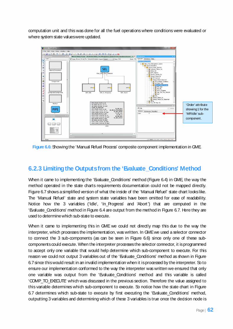
Notice how the reference variable ‘COMP_TO_EXECUTE’ stores an integer value to determine which
sub-component is executed from ‘MR Idle’, ‘MR In_Progress’ and ‘MR Abort’. The reason for this is
because each sub-component defined in GME has an order number. If we recall the class diagram
showing the exogenous connectors component model in Figure 3.5 from Chapter 3 each component
has an order number that helps the exogenous connector determine which sub-component to
execute. So the ‘COMP_TO_EXECUTE’ variable will be used by the selector connector in the ‘Manual
Refuel Process’ composite component to determine which sub-component to execute from ‘MR Idle’,
‘MR In_Progress’ and ‘MR Abort’. Figure 6.6 shows the GME implementation of the ‘Manual Refuel
Process’ composite component. The attribute called ‘Order’ indicates the order value of the
component. It currently shows a value of ‘1’ because the first sub-component called ‘MR Idle’ has
been selected.
It is important to point out that the code in Figure 6.5 was written inside the computation unit
located inside the ‘MR Evaluate Conditions’ atomic component. The code is always defined inside the
Page | 61
computation unit and this was done for all the fuel operations where conditions were evaluated or
where system state values were updated.
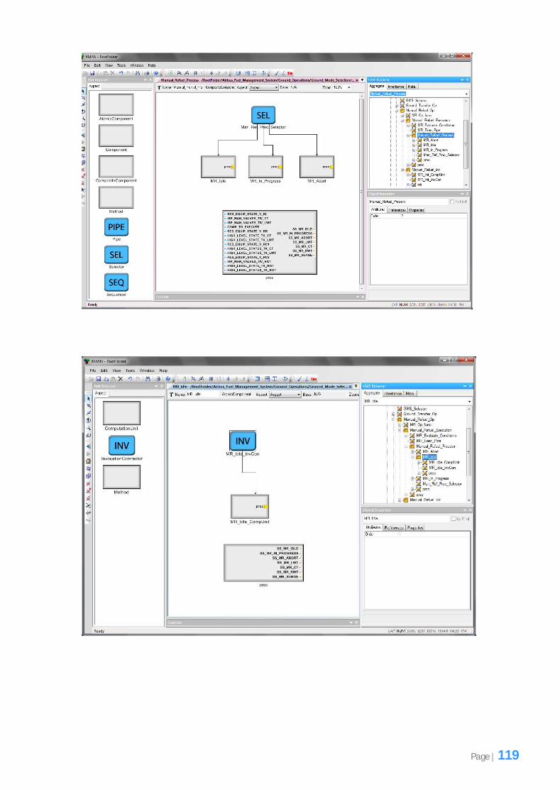
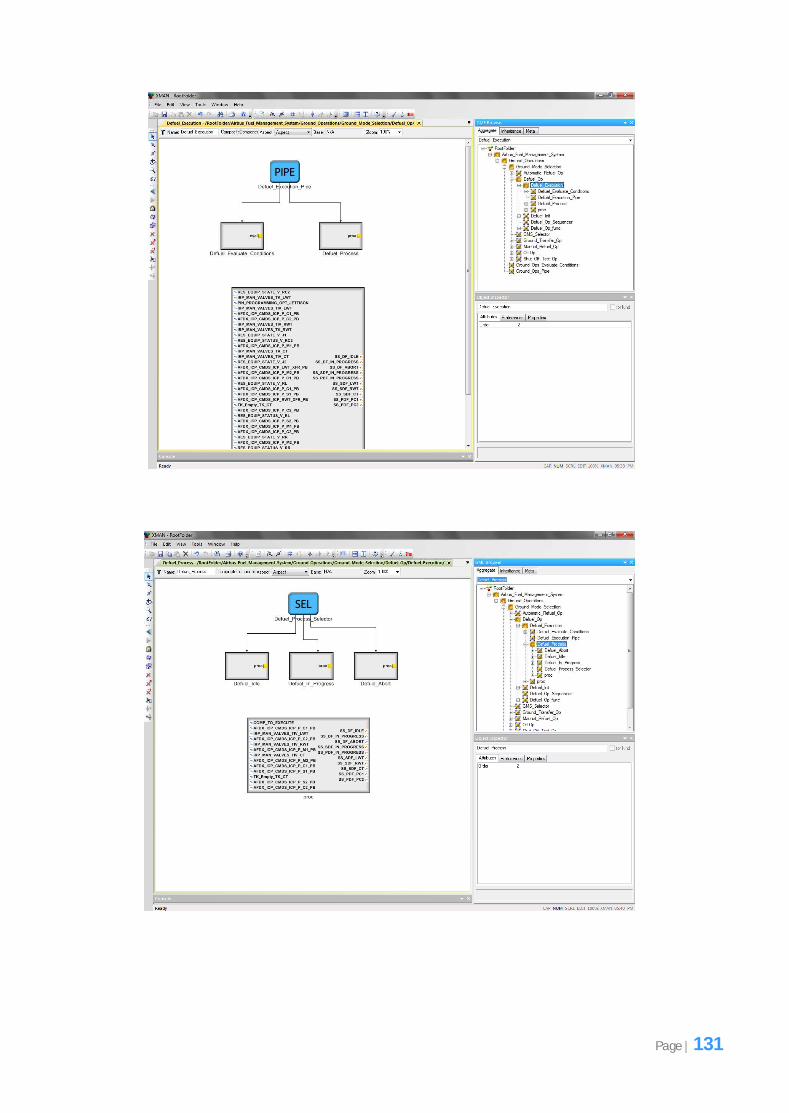
Figure 6.6: Showing the ‘Manual Refuel Process’ composite component implementation in GME.
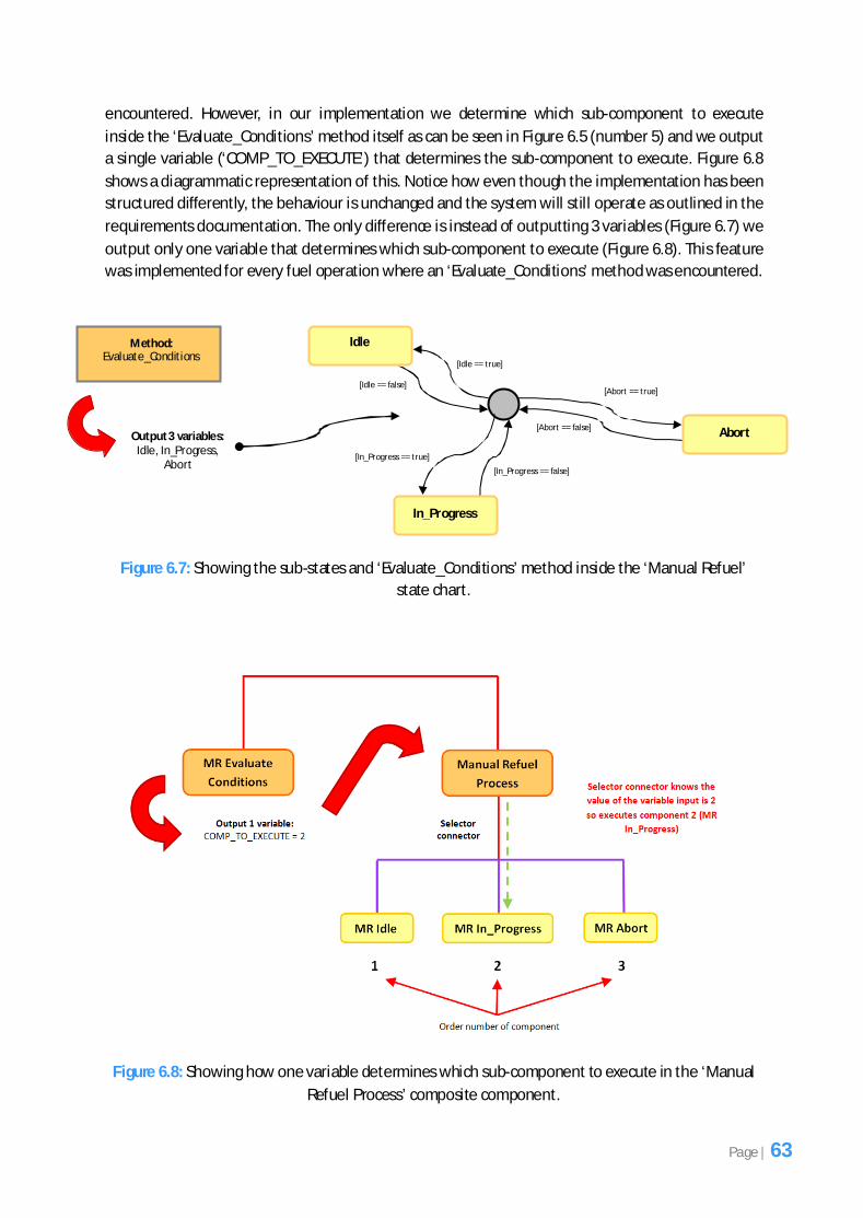
6.2.3 Limiting the Outputs from the ‘Evaluate_Conditions’ Method
When it came to implementing the ‘Evaluate_Conditions’ method (Figure 6.4) in GME, the way the
method operated in the state charts requirements documentation could not be mapped directly.
Figure 6.7 shows a simplified version of what the inside of the ‘Manual Refuel’ state chart looks like.
The ‘Manual Refuel’ state and system state variables have been omitted for ease of readability.
Notice how the 3 variables (‘Idle’, ‘In_Progress’ and ‘Abort’) that are computed in the
‘Evaluate_Conditions’ method in Figure 6.4 are output from the method in Figure 6.7. Here they are
used to determine which sub-state to execute.
When it came to implementing this in GME we could not directly map this due to the way the
interpreter, which processes the implementation, was written. In GME we used a selector connector
to connect the 3 sub-components (as can be seen in Figure 6.6) since only one of these sub-
components could execute. When the interpreter processes the selector connector, it is programmed
to accept only one variable that would help determine which sub-component to execute. For this
reason we could not output 3 variables out of the ‘Evaluate_Conditions’ method as shown in Figure
6.7 since this would result in an invalid implementation when it is processed by the interpreter. So to
ensure our implementation conformed to the way the interpreter was written we ensured that only
one variable was output from the ‘Evaluate_Conditions’ method and this variable is called
‘COMP_TO_EXECUTE’ which was discussed in the previous section. Therefore the value assigned to
this variable determines which sub-component to execute. So notice how the state chart in Figure
6.7 determines which sub-state to execute by first executing the ‘Evaluate_Conditions’ method,
outputting 3 variables and determining which of these 3 variables is true once the decision node is
‘Order’ attribute
showing 1 for the
‘MR Idle’ sub-
component.
Page | 62
encountered. However, in our implementation we determine which sub-component to execute
inside the ‘Evaluate_Conditions’ method itself as can be seen in Figure 6.5 (number 5) and we output
a single variable (‘COMP_TO_EXECUTE’) that determines the sub-component to execute. Figure 6.8
shows a diagrammatic representation of this. Notice how even though the implementation has been
structured differently, the behaviour is unchanged and the system will still operate as outlined in the
requirements documentation. The only difference is instead of outputting 3 variables (Figure 6.7) we
output only one variable that determines which sub-component to execute (Figure 6.8). This feature
was implemented for every fuel operation where an ‘Evaluate_Conditions’ method was encountered.
Figure 6.7: Showing the sub-states and ‘Evaluate_Conditions’ method inside the ‘Manual Refuel’
state chart.
Figure 6.8: Showing how one variable determines which sub-component to execute in the ‘Manual
Refuel Process’ composite component.
In_Progress
[Idle == true]
Idle
[Idle == false]
[In_Progress == false]
[In_Progress == true]
Abort
[Abort == true]
[Abort == false]
Method: Evaluate_Conditions
Output 3 variables: Idle, In_Progress,
Abort
Page | 63
6.2.4 Restructuring Certain Parts of the System
There were occasions during implementation when the structure of a fuel operation for a particular
component had to be redesigned due to good system development practice. If you look at Figure 6.4
you will notice that the 4 variables under the boolean variable ‘MR_ANY_TIV_OPEN’ are not
implemented in the code in Figure 6.5. The reason for this was because these variables are actually
required by the ‘MR_Surge_Protection’ sub-component and the problem was this component is
located inside the ‘MR In_Progress’ composite component (Figure 6.6). Figure 6.9 shows the
contents of the ‘MR In_Progress’ composite component in GME.
We could have easily implemented the 4 variables associated with the boolean variable
‘MR_ANY_TIV_OPEN’ shown in Figure 6.4 inside the code in Figure 6.5 and passed them out of the
‘Evaluate_Conditions’ method as output parameters and then pass them as input parameters into
the ‘Manual Refuel Process’ composite component so that they could be forwarded to the ‘MR
In_Progress’ sub-component and used by the ‘MR_Surge_Protection’ sub-component. However, this
was avoided because due to good software development practice we felt it was more ideal to isolate
these variables and place them inside the component that actually requires them which in this case
is the ‘MR_Surge_Protection’ sub-component. Recall that a software component is a unit of software
that has a well defined purpose and is loosely coupled and highly cohesive. Cohesion describes the
interactions within components. The more cohesive a component, the more related the internal
parts of the component to each other and to its whole purpose [14]. Therefore, for this reason we
felt it was important to isolate these variables and place them inside the ‘MR_Surge_Protection’ sub-
component and this would make the internal parts of this component more related since this is
where they are used. If we were to implement these variables in the ‘Evaluate_Conditions’ method
(Figure 6.5) then the ‘MR Evaluate Conditions’ atomic component (Figure 6.8) that contains this
method would not be considered highly cohesive since the 4 variables associated with the boolean
variable ‘MR_ANY_TIV_OPEN’ in Figure 6.4 would be unrelated to the rest of the code as they are
not used by any sub-component except the ‘MR_Surge_Protection’ sub-component, which is located
further down the hierarchy of components.
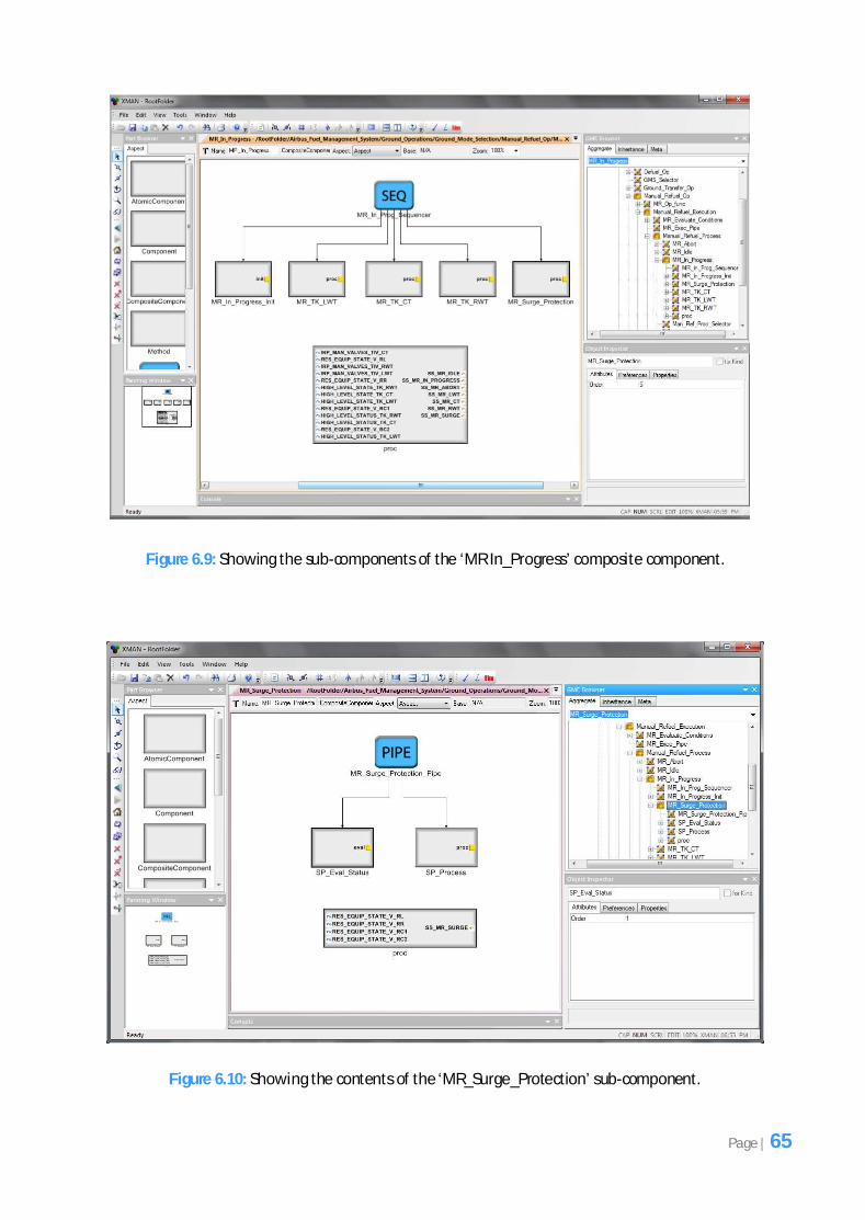
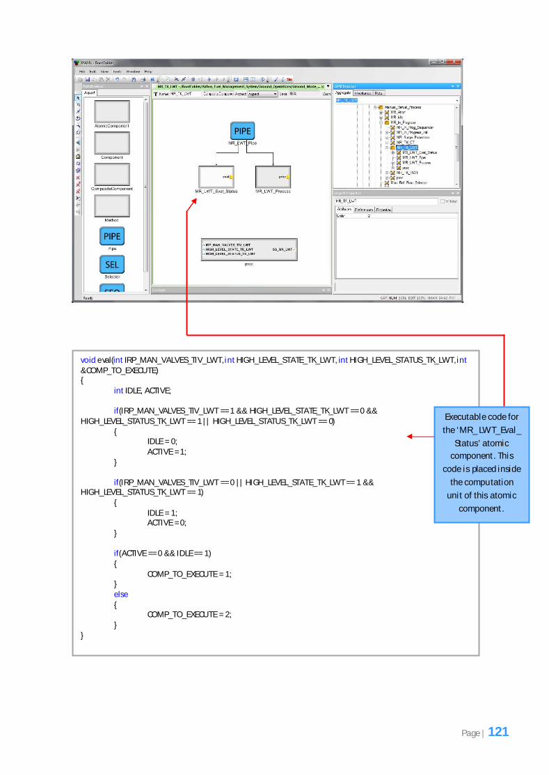
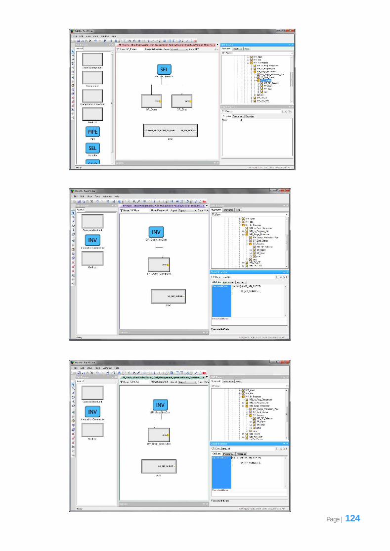
Therefore the system was restructured by adding a new atomic component called ‘SP_Eval_Status’
inside the ‘MR_Surge_Protection’ sub-component and connecting this atomic component with a
composite component called ‘SP_Process’ using a pipe connector. Figure 6.10 shows this. The
method inside the ‘SP_Eval_Status’ atomic component would perform some computation, similar to
the computation performed in the ‘Evaluate_Conditions’ method, by using the 4 variables associated
with the boolean variable ‘MR_ANY_TIV_OPEN’ in Figure 6.4 and it will output a variable to
determine which atomic component from ‘SP_Open’ and ‘SP_Shut’ to execute (Figure 6.11). These
two components are actually located inside the ‘SP_Process’ composite component (Figure 6.10).
Notice that because the ‘SP_Eval_Status’ atomic component will output a variable that will help
determine which sub-component to execute in the ‘SP_Process’ composite component, we have
used a pipe connector to connect these two components because the pipe connector allows values
output from one component to be passed as inputs into the next component which is exactly what
was required here.
Page | 64
Figure 6.9: Showing the sub-components of the ‘MR In_Progress’ composite component.
Figure 6.10: Showing the contents of the ‘MR_Surge_Protection’ sub-component.
Page | 65
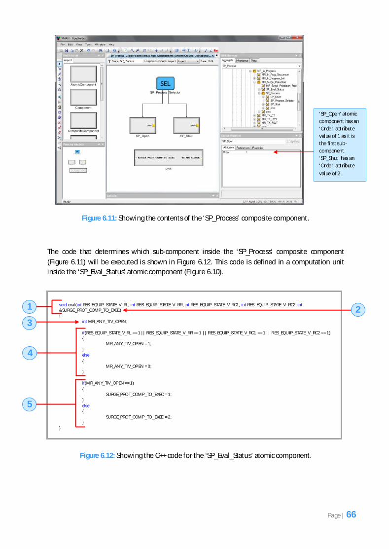
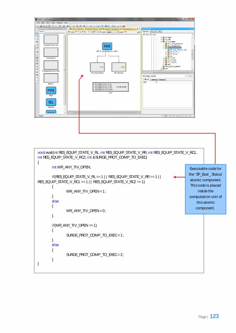
Figure 6.11: Showing the contents of the ‘SP_Process’ composite component.
The code that determines which sub-component inside the ‘SP_Process’ composite component
(Figure 6.11) will be executed is shown in Figure 6.12. This code is defined in a computation unit
inside the ‘SP_Eval_Status’ atomic component (Figure 6.10).
Figure 6.12: Showing the C++ code for the ‘SP_Eval_Status’ atomic component.
void eval(int RES_EQUIP _STATE_V_RL, int RES_EQUIP _STATE_V_RR , int RES_EQUIP _STATE_V_RC1, int RES_EQUIP _STATE_V_RC2, int &SURGE_PROT_COMP_TO_EXEC) {
int MR_AN Y_TIV_OPEN;
if(RES_EQUIP _STATE_V_RL == 1 || R ES_EQU IP_STATE_V_RR == 1 || R ES_EQUIP _STATE_V_RC1 == 1 || R ES_EQU IP_STATE_V_RC2 == 1) { MR_AN Y_TIV_OP EN = 1;
} else
{ MR_AN Y_TIV_OP EN = 0; }
if(MR_AN Y_TIV_OP EN == 1)
{ SURGE_PRO T_COMP _TO _EXEC = 1; }
else {
SURGE_PRO T_COMP _TO _EXEC = 2; } }
1 2
3
4
5
‘SP_Open’ atomic
component has an
‘Order’ attribute
value of 1 as it is
the first sub-
component.
‘SP_Shut’ has an
‘Order’ attribute
value of 2.
Page | 66
The code in Figure 6.12 will be explained by referring to each part of the code by number. Number 1
refers to the method signature. All the variables associated with the boolean variable
‘MR_ANY_TIV_OPEN’ in Figure 6.4 are being passed as input parameters into the method here.
Number 2 refers to a reference variable called ‘SURGE_PROT_COMP_TO_EXEC’ which is going to
determine which sub-component to execute out of ‘SP_Open’ and ‘SP_Shut’ (Figure 6.11). In GME
this variable will be passed out of the ‘SP_Eval_Status’ atomic component as an output parameter
and passed into the ‘SP_Process’ composite component as an input parameter (Figure 6.10) to
determine which sub-component to execute in Figure 6.11.
Number 3 refers to a local variable being defined called ‘MR_ANY_TIV_OPEN’, exactly the same as
the variable in Figure 6.4.
Number 4 refers to the code where the computation is performed. If either of the variables passed in
as input parameters to the method have a value of 1 (true) then the ‘MR_ANY_TIV_OPEN’ variable is
set to 1 (true) else it is set to 0 (false).
Number 5 refers to the code which is similar to the ending of the code in Figure 6.5. Here if the local
variable ‘MR_ANY_TIV_OPEN’ is equivalent to 1 (true) then the ‘SURGE_PROT_COMP_TO_EXEC’
variable is set to 1 which means the ‘SP_Open’ atomic component located inside the ‘SP_Process’
composite component (Figure 6.11) will be executed, since it has an ‘Order’ attribute value of 1, else
the ‘SURGE_PROT_COMP_TO_EXEC’ variable is set to 2 which means the ‘SP_Shut’ atomic
component will be executed because it has an ‘Order’ attribute value of 2.
Notice how although the structure of the system has been altered the behaviour is unchanged
because the system will still operate as outlined in the requirements documentation. The only
difference here is that instead of computing the 4 variables associated with the boolean variable
‘MR_ANY_TIV_OPEN’ inside the ‘Evaluate_Conditions’ method (Figure 6.5), they are now computed
in the ‘SP_Eval_Status’ atomic component’s method located inside the ‘MR_Surge_Protection’
component (Figure 6.10) and the method that performs this computation is shown in Figure 6.12.
Since these 4 variables were only required by the ‘MR_Surge_Protection’ composite component, this
justified the need to restructure the system in this manner to ensure our implementation was highly
cohesive.
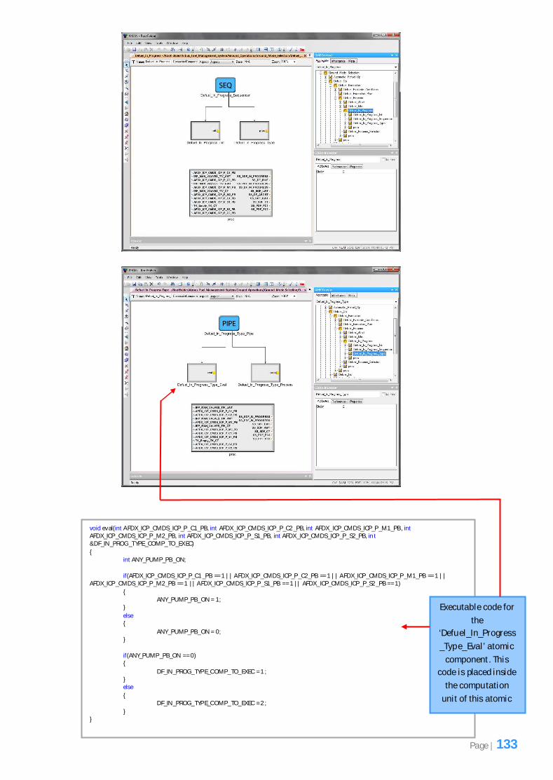
6.2.5 Implementing Composite Methods
A composite method is a method that has been defined inside a composite component. It is mainly
used by an exogenous connector to determine which parameters to supply to which sub-components
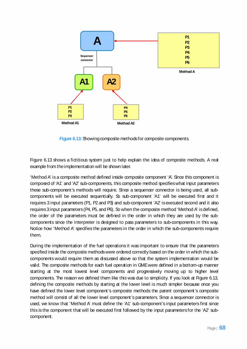
and what parameters to output of the composite component. Figure 6.13 shows an example of
composite methods for 3 composite components using a sequencer connector.
Page | 67
Figure 6.13: Showing composite methods for composite components.
Figure 6.13 shows a fictitious system just to help explain the idea of composite methods. A real
example from the implementation will be shown later.
‘Method A’ is a composite method defined inside composite component ‘A’. Since this component is
composed of ‘A1’ and ‘A2’ sub-components, this composite method specifies what input parameters
these sub-component’s methods will require. Since a sequencer connector is being used, all sub-
components will be executed sequentially. So sub-component ‘A1’ will be executed first and it
requires 3 input parameters (P1, P2 and P3) and sub-component ‘A2’ is executed second and it also
requires 3 input parameters (P4, P5, and P6). So when the composite method ‘Method A’ is defined,
the order of the parameters must be defined in the order in which they are used by the sub-
components since the interpreter is designed to pass parameters to sub-components in this way.
Notice how ‘Method A’ specifies the parameters in the order in which the sub-components require
them.
During the implementation of the fuel operations it was important to ensure that the parameters
specified inside the composite methods were ordered correctly based on the order in which the sub-
components would require them as discussed above so that the system implementation would be
valid. The composite methods for each fuel operation in GME were defined in a bottom-up manner
starting at the most lowest level components and progressively moving up to higher level
components. The reason we defined them like this was due to simplicity. If you look at Figure 6.13,
defining the composite methods by starting at the lower level is much simpler because once you
have defined the lower level component’s composite methods the parent component’s composite
method will consist of all the lower level component’s parameters. Since a sequencer connector is
used, we know that ‘Method A’ must define the ‘A1’ sub-component’s input parameters first since
this is the component that will be executed first followed by the input parameters for the ‘A2’ sub-
component.
A
A1 A2
Method A
P1
P2 P3 P4 P5 P6
Sequencer
connector
P4 P5 P6
Method A2
P1 P2
P3
Method A1
Page | 68
Figure 6.14 shows the GME implementation for the ‘MR In_Progress’ composite component. It
shows how input parameters have been ordered in the composite method ‘proc’ so that they can be
supplied to the sub-components in that order when the interpreter processes this GME
implementation. Notice how a sequencer connector has been used. This means that all the sub-
components at this level are going to be executed sequentially one after another. The first sub-
component (MR_In_Progress_Init) does not require any input parameters as it uses output
parameters and outputs them from itself. These output parameters are listed on the right hand side
of the composite method ‘proc’ in Figure 6.14 which means they are passed out of the ‘MR
In_Progress’ composite component.
When composite methods were implemented in GME they were double checked to ensure the order
of the parameters were correct since a slight error in the order could result in failure when the
interpreter was executed.
Figure 6.14: Showing how parameters in GME are ordered in the composite method for the ‘MR
In_Progress’ composite component so they can be supplied in that order to the sub-components.
Only samples of screenshots for the fuel management system implementation were shown in this
chapter. The full set of screenshots for the fuel management system implementation in GME can be
viewed in appendix C.
Page | 69
During and after the implementation, it was vital to ensure that the fuel management system was
tested so that it conformed to the tool (which is composed of the exogenous connectors’ component
model and interpreter) supplied to us by the School of Computer Science so that our implementation
of the system would be considered valid. Numerous testing techniques were performed which are
discussed in this chapter.
7.1 Testing Strategy
The testing strategy refers to the plan of how testing was approached. It was developed before
implementation began so that it was clear how the system would be tested. The following outlines
the different testing techniques used:
o Unit Testing – During the development of the system, unit testing was continuously
performed on individual atomic components.
o Integration Testing – This form of testing was necessary when two or more components
were combined (composite component). It was continuously performed during
implementation.
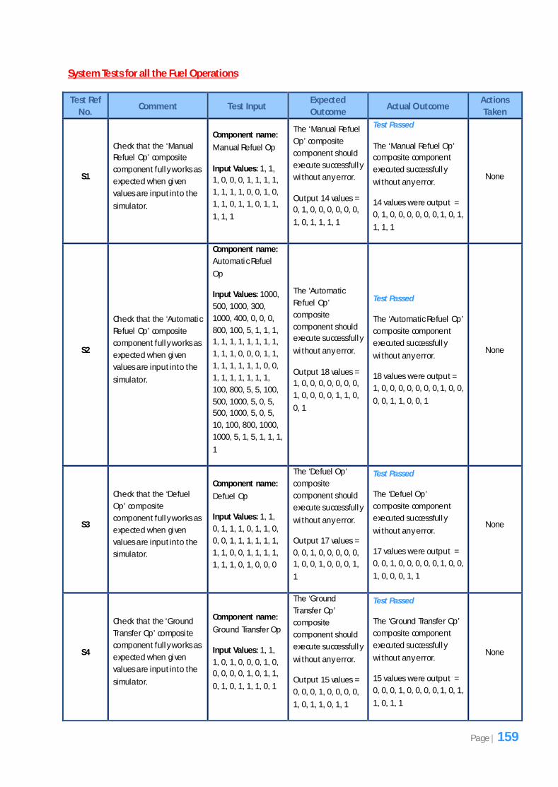
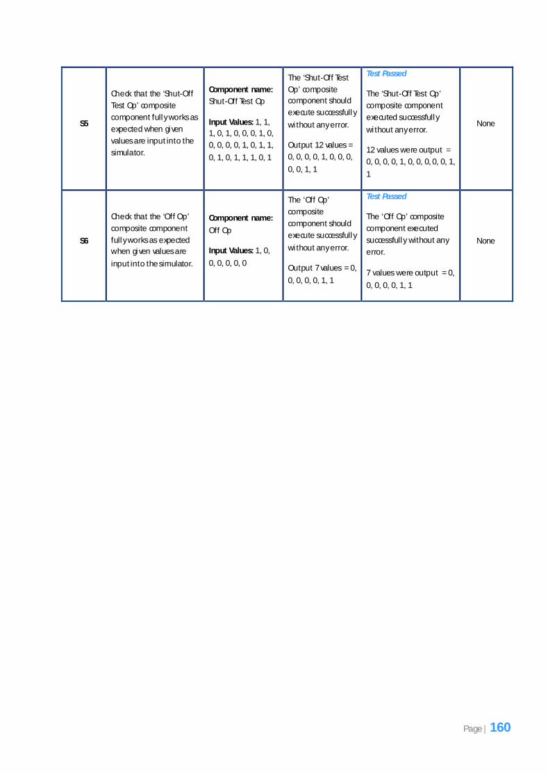
o System Testing – This involved testing each fuel operation of the system as a whole, once it
was fully implemented. Each fuel operation was composed of multiple composite and atomic
components and composite methods.
o Regression Testing – This form of testing involved checking that no errors were introduced as
a result of making changes to certain parts of the system’s structure in GME during
implementation. It involved rerunning all the tests for a given composite component to
ensure the sub-components still operated correctly.
The testing strategy helped guide the process of testing to ensure that all aspects of the system had
been tested thoroughly, which was crucial since the nature of the system was safety-critical.
7.2 Test Plan
Before testing could be undertaken, it was important to have a test plan in place which would guide
the testing process. The test plan was based on the testing strategy which defined a set of test cases7
to be carried out and the expected and actual outcomes of the tests. The test plan was created
7 A set of conditions under which a tester will determine whether a system meets its specification.
Fuel Management System Testing
Chapter 7
Page | 70
during the design phase once the structure of the system was determined. Table 7.1 shows the
structure of the test plan.
Test Ref No. Comment Test Input Expected Outcome
Actual Outcome
Actions Taken
A unique
identifier for
the test
A comment
explaining the
purpose of the
test
The actual data
to be used in
the test
The outcome of
the test
predicted
The actual
result of the
test
Any actions
taken if the
outcome was
not as expected
Table 7.1: Test plan structure.
7.3 How Testing was Performed
During implementation the main testing techniques that were used were unit and integration testing.
Each fuel operation was tested in a bottom-up manner starting at the lowest level components and
progressively moving up to higher level components. The lowest level components were mainly
atomic components that contained a computation unit, invocation connector and a method and the
higher level components were composite components that were composed of a combination of
atomic and composite components and composite methods including exogenous connectors.
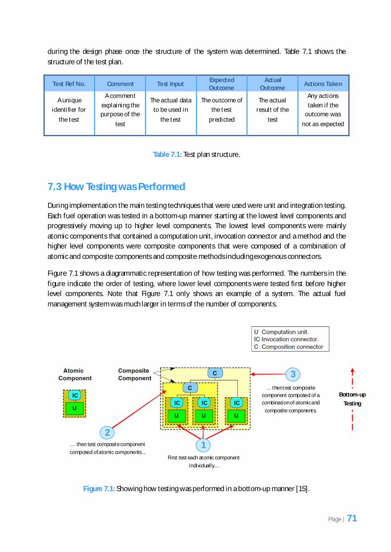
Figure 7.1 shows a diagrammatic representation of how testing was performed. The numbers in the
figure indicate the order of testing, where lower level components were tested first before higher
level components. Note that Figure 7.1 only shows an example of a system. The actual fuel
management system was much larger in terms of the number of components.
Figure 7.1: Showing how testing was performed in a bottom-up manner [15].
First test each atomic component
individually....
.... then test composite component
composed of atomic components...
... then test composite
component composed of a
combination of atomic and
composite components.
1
2
3
Bottom-up
Testing
Page | 71
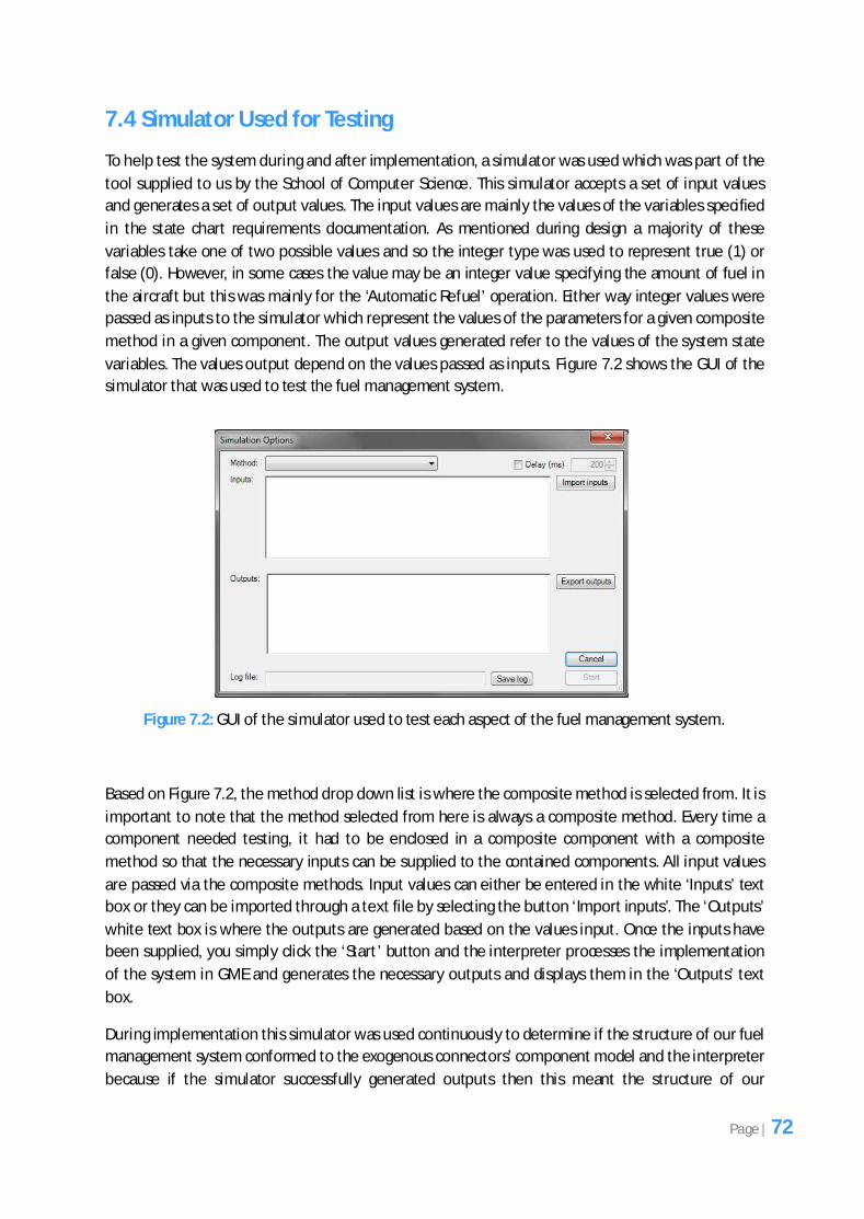
7.4 Simulator Used for Testing
To help test the system during and after implementation, a simulator was used which was part of the
tool supplied to us by the School of Computer Science. This simulator accepts a set of input values
and generates a set of output values. The input values are mainly the values of the variables specified
in the state chart requirements documentation. As mentioned during design a majority of these
variables take one of two possible values and so the integer type was used to represent true (1) or
false (0). However, in some cases the value may be an integer value specifying the amount of fuel in
the aircraft but this was mainly for the ‘Automatic Refuel’ operation. Either way integer values were
passed as inputs to the simulator which represent the values of the parameters for a given composite
method in a given component. The output values generated refer to the values of the system state
variables. The values output depend on the values passed as inputs. Figure 7.2 shows the GUI of the
simulator that was used to test the fuel management system.
Figure 7.2: GUI of the simulator used to test each aspect of the fuel management system.
Based on Figure 7.2, the method drop down list is where the composite method is selected from. It is
important to note that the method selected from here is always a composite method. Every time a
component needed testing, it had to be enclosed in a composite component with a composite
method so that the necessary inputs can be supplied to the contained components. All input values
are passed via the composite methods. Input values can either be entered in the white ‘Inputs’ text
box or they can be imported through a text file by selecting the button ‘Import inputs’. The ‘Outputs’
white text box is where the outputs are generated based on the values input. Once the inputs have
been supplied, you simply click the ‘Start’ button and the interpreter processes the implementation
of the system in GME and generates the necessary outputs and displays them in the ‘Outputs’ text
box.
During implementation this simulator was used continuously to determine if the structure of our fuel
management system conformed to the exogenous connectors’ component model and the interpreter
because if the simulator successfully generated outputs then this meant the structure of our
Page | 72
implementation was valid. If the structure was invalid an error message dialog would appear which
meant that the structure required correcting.
7.5 Testing the Fuel Management System
The number of tests that were performed overall was relatively large and so only examples of the
tests will be shown here for each testing technique.
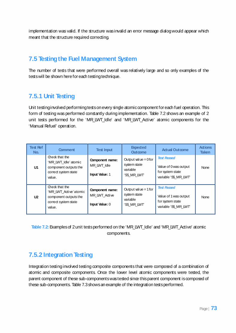
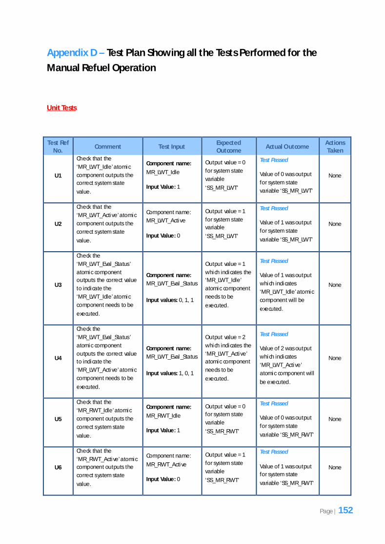
7.5.1 Unit Testing
Unit testing involved performing tests on every single atomic component for each fuel operation. This
form of testing was performed constantly during implementation. Table 7.2 shows an example of 2
unit tests performed for the ‘MR_LWT_Idle’ and ‘MR_LWT_Active’ atomic components for the
‘Manual Refuel’ operation.
Test Ref No.
Comment Test Input Expected Outcome
Actual Outcome Actions Taken
U1
Check that the
‘MR_LWT_Idle’ atomic
component outputs the
correct system state
value.
Component name:
MR_LWT_Idle
Input Value: 1
Output value = 0 for
system state
variable
‘SS_MR_LWT’
Test Passed
Value of 0 was output
for system state
variable ‘SS_MR_LWT’
None
U2
Check that the
‘MR_LWT_Active’ atomic
component outputs the
correct system state
value.
Component name:
MR_LWT_Active
Input Value: 0
Output value = 1 for
system state
variable
‘SS_MR_LWT’
Test Passed
Value of 1 was output
for system state
variable ‘SS_MR_LWT’
None
Table 7.2: Examples of 2 unit tests performed on the ‘MR_LWT_Idle’ and ‘MR_LWT_Active’ atomic
components.
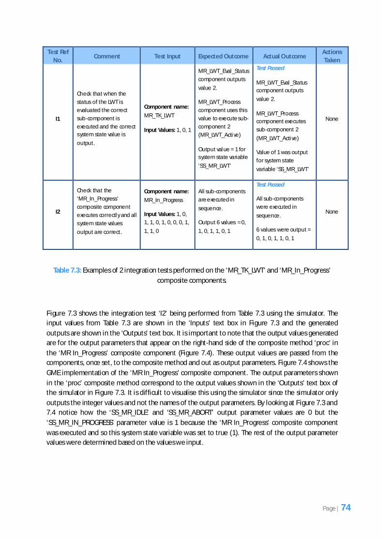
7.5.2 Integration Testing
Integration testing involved testing composite components that were composed of a combination of
atomic and composite components. Once the lower level atomic components were tested, the
parent component of these sub-components was tested since this parent component is composed of
these sub-components. Table 7.3 shows an example of the integration tests performed.
Page | 73
Test Ref
No. Comment Test Input Expected Outcome Actual Outcome
Actions
Taken
I1
Check that when the
status of the LWT is
evaluated the correct
sub-component is
executed and the correct
system state value is
output.
Component name:
MR_TK_LWT
Input Values: 1, 0, 1
MR_LWT_Eval_Status
component outputs
value 2.
MR_LWT_Process
component uses this
value to execute sub-
component 2
(MR_LWT_Active)
Output value = 1 for
system state variable
‘SS_MR_LWT’
Test Passed
MR_LWT_Eval_Status
component outputs
value 2.
MR_LWT_Process
component executes
sub-component 2
(MR_LWT_Active)
Value of 1 was output
for system state
variable ‘SS_MR_LWT’
None
I2
Check that the
‘MR_In_Progress’
composite component
executes correctly and all
system state values
output are correct.
Component name:
MR_In_Progress
Input Values: 1, 0,
1, 1, 0, 1, 0, 0, 0, 1,
1, 1, 0
All sub-components
are executed in
sequence.
Output 6 values = 0,
1, 0, 1, 1, 0, 1
Test Passed
All sub-components
were executed in
sequence.
6 values were output =
0, 1, 0, 1, 1, 0, 1
None
Table 7.3: Examples of 2 integration tests performed on the ‘MR_TK_LWT’ and ‘MR_In_Progress’
composite components.
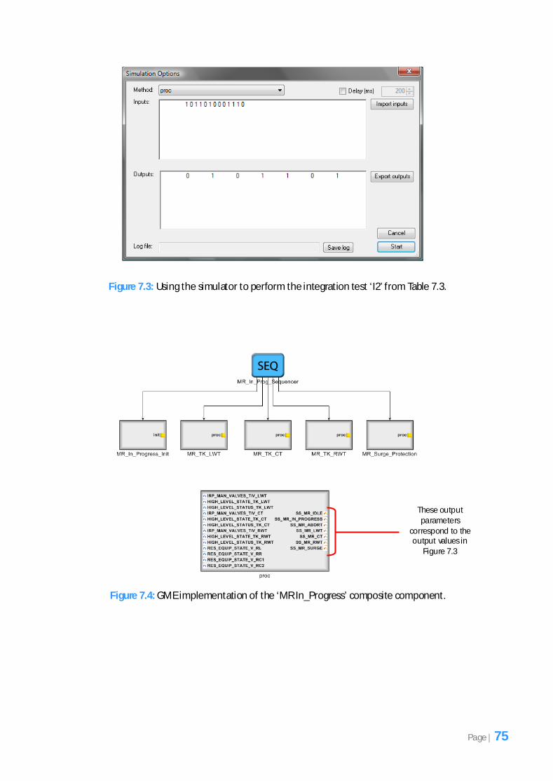
Figure 7.3 shows the integration test ‘I2’ being performed from Table 7.3 using the simulator. The
input values from Table 7.3 are shown in the ‘Inputs’ text box in Figure 7.3 and the generated
outputs are shown in the ‘Outputs’ text box. It is important to note that the output values generated
are for the output parameters that appear on the right-hand side of the composite method ‘proc’ in
the ‘MR In_Progress’ composite component (Figure 7.4). These output values are passed from the
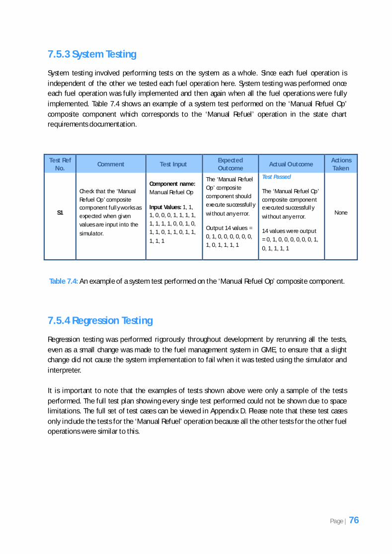
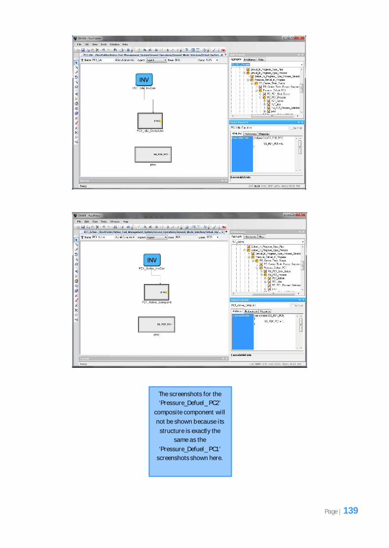
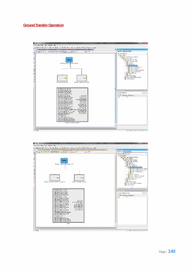
components, once set, to the composite method and out as output parameters. Figure 7.4 shows the
GME implementation of the ‘MR In_Progress’ composite component. The output parameters shown
in the ‘proc’ composite method correspond to the output values shown in the ‘Outputs’ text box of
the simulator in Figure 7.3. It is difficult to visualise this using the simulator since the simulator only
outputs the integer values and not the names of the output parameters. By looking at Figure 7.3 and
7.4 notice how the ‘SS_MR_IDLE’ and ‘SS_MR_ABORT’ output parameter values are 0 but the
‘SS_MR_IN_PROGRESS’ parameter value is 1 because the ‘MR In_Progress’ composite component
was executed and so this system state variable was set to true (1). The rest of the output parameter
values were determined based on the values we input.
Page | 74
Figure 7.3: Using the simulator to perform the integration test ‘I2’ from Table 7.3.
Figure 7.4: GME implementation of the ‘MR In_Progress’ composite component.
These output parameters
correspond to the output values in
Figure 7.3
Page | 75
7.5.3 System Testing
System testing involved performing tests on the system as a whole. Since each fuel operation is
independent of the other we tested each fuel operation here. System testing was performed once
each fuel operation was fully implemented and then again when all the fuel operations were fully
implemented. Table 7.4 shows an example of a system test performed on the ‘Manual Refuel Op’
composite component which corresponds to the ‘Manual Refuel’ operation in the state chart
requirements documentation.
Test Ref No.
Comment Test Input Expected Outcome
Actual Outcome Actions Taken
S1
Check that the ‘Manual
Refuel Op’ composite
component fully works as
expected when given
values are input into the
simulator.
Component name:
Manual Refuel Op
Input Values: 1, 1,
1, 0, 0, 0, 1, 1, 1, 1,
1, 1, 1, 1, 0, 0, 1, 0,
1, 1, 0, 1, 1, 0, 1, 1,
1, 1, 1
The ‘Manual Refuel
Op’ composi te
component should
execute successfully
without any error.
Output 14 values =
0, 1, 0, 0, 0, 0, 0, 0,
1, 0, 1, 1, 1, 1
Test Passed
The ‘Manual Refuel Op’
composite component
executed successfully
without any error.
14 values were output
= 0, 1, 0, 0, 0, 0, 0, 0, 1,
0, 1, 1, 1, 1
None
Table 7.4: An example of a system test performed on the ‘Manual Refuel Op’ composite component.
7.5.4 Regression Testing
Regression testing was performed rigorously throughout development by rerunning all the tests,
even as a small change was made to the fuel management system in GME, to ensure that a slight
change did not cause the system implementation to fail when it was tested using the simulator and
interpreter.
It is important to note that the examples of tests shown above were only a sample of the tests
performed. The full test plan showing every single test performed could not be shown due to space
limitations. The full set of test cases can be viewed in Appendix D. Please note that these test cases
only include the tests for the ‘Manual Refuel’ operation because all the other tests for the other fuel
operations were similar to this.
Page | 76
This chapter involves discussing relevant issues that were considered interesting which arose during
the development of the fuel management system. It focuses on the additional work that was carried
out after the implementation of the fuel management system.
8.1 Limitation of the Selector Connector Code in the Interpreter
During the analysis of the interpreter (which is responsible for processing the fuel management
system implementation in GME to ensure it conforms to the exogenous connectors’ component
model and also allows the system to be tested via a simulator) we felt that the code that was
responsible for processing a selector connector in GME had its limitations. This selector connector
was programmed to accept only a single value to determine which sub-component to execute.
However, the state charts in the requirements documentation are modelled differently to the way
the selector connector behaves. Figure 8.1 shows the ‘Manual Refuel’ state chart from the state
chart requirements documentation. Once the ‘Evaluate_Conditions’ method is executed 3 variables
are output and a single sub-state from ‘Idle’, ‘In_Progress’ or ‘Abort’ is executed depending on
whichever of these variables has a value of ‘true’. However, when it came to mapping the output of
these 3 variables from the ‘Evaluate_Conditions’ method in GME during implementation so they
could be used to determine which sub-component to execute from ‘MR_Idle’, ‘MR In_Progress’ and
‘MR Abort’, it could not be mapped directly since the interpreter only allowed one value to be passed
to the selector connector to determine the sub-component to execute in GME.
Therefore, after the fuel management system had been fully implemented in GME we felt that it
would be ideal to improve the way the selector connector behaved and we attempted to improve the
implementation for the selector connector so that it would behave similarly to the way the state
charts are represented in the requirements documentation. This would mean that we would be able
to map the state chart shown in Figure 8.1 directly, in terms of the 3 variables output to determine
which sub-component to execute, when implementing the system in GME.
Implementation Discussion
Chapter 8
Page | 77
Figure 8.1: State chart for the ‘Manual Refuel’ operation
8.2 Improving the Existing Selector Connector Code
Figure 8.2 shows the code written for the current selector connector. Note that this is the existing
code that is used in the interpreter to process the selector connector. Figure 8.3 shows our improved
version of the code for the selector connector. Note that in both figures only the relevant code is
being shown, the code that was irrelevant has been omitted.
Page | 78
Figure 8.2: The C++ selector connector code for the interpreter.
Only the important parts of the code will be discussed here since the code is self explanatory as it
has been commented. The code in Figure 8.2 will be explained by referring to it by number. Number
1 refers to the first input parameter (which is the value passed from the ‘Evaluate_Conditions’
method to help determine which sub-component to execute) which is retrieved and stored in a
variable called ‘param’. Number 2 retrieves each sub-component connected to the selector
connecter and the getOrder() method is invoked to retrieve each sub-component’s ‘Order’ value
(recall that this is an attribute given to each component in GME which determines the order of the
component). This ‘Order’ value is compared against the value of the variable ‘param’ and if they
match then this is the sub-component that is executed.
The code in Figure 8.3 shows the improved version of the selector connector code to reflect the way
the state charts are represented in the requirements documentation, which will mean that they can
be mapped directly if this code is used instead of the code in Figure 8.2.
...... code omitted // using the first input param to select sub-component Any* param = curInputs[0];
// get (sub-)components connected to this connector std::multiset<XMAN_BON::Component> subComponents = object->getControlsSubComponentsDsts(); // look for the component that sastisfies the selection value // and asks it to be visited for (std::multiset<XMAN_BON::Component>::iterator it = subComponents.begin(); it != subComponents.end(); ++it) { if ((*it)->getOrder() == param->toInteger()) { ..... code omitted (*it)->accept(this); // ask the component to accept this visitor
// get all subcomponents connected to this connector
std::multiset<XMAN_BO N::Component> subComponents = object->getControlsSubComponentsDsts(); // order the subcomponents according to `order' attribute XMAN_BON::Component * orderedComponents = new XMAN_BON::Component[subComponents.size()];
std::multiset<XMAN_BO N::Component>::iterator it = subComponents.begin(); // get iterator // while a next component s till exists while(it != subComponents.end()) {
orderedComponents[((*it)->getOrder())-1] = (*it); // assign the component to the index location of the order value - 1 in the vector ++it; // move iterator to point to next object }
int totalComponents = subComponents.size(); // get the total number of sub components connected to this connector vector<Any*> componentSelectorParameters; // stores all the parameters that determine which component to execute. One parameter per
component.
// get the 1st number of parameters from curInputs based on the total number of components a nd add them to the vector tha t stores these parameters
for(int i=0; i < totalComponents; i++) { componentSelectorParameters.push_back(curInputs[i]); // add the parameter to the vector
} ...... code omitted bool componentVariableTrue = false; // determines if the input parameter has a value of true
int indexOfComponentToExecute = -1; // indicates the index position of the component to visit and execute. -1 is default value which will indicate no component will be executed as no boolean variable for component selection is true.
// determine which of the variables is set to true as this is the component which will be executed for(vector<Any>::iterator it = componentSelectorParameters.begin(); it != componentSelectorParameters.end() && !componentVariableTrue; ++it)
{ Any* currentParam = (*it); // get the current parameter // if the current parameters value is 1 then....
if((currentParam->toInt()) == 1) { // get the position of this input parameter as this will correspond to the component to vis it and execute.
indexOfComponentToExecute = it - componentSelectorParameters.begin(); componentVariableTrue = true; // will help break out of loop and avoid unnecessary iterating as the parameter has been
found. } } // if a true boolean variable has been found amoung the input parameters for component se lection ( indicated by a postive index position) then....
if(indexOfComponentToExecute >=0) { ...... code omitted orderedComponents[indexOfComponentToExecute]->accept(this); // get the selected component to accept this visitor
...... code omitted } ...... code omitted
return true; }
1
2
3
4
Page | 80
The code in Figure 8.3 will be explained by referring to each part by number. In number 1 we first get
all the sub-components connected to the selector connector and order all these sub-components
based on the value of their ‘Order’ attribute in GME and then we count the total number of sub-
components connected to this selector connector. In number 2 the first set of input parameters are
retrieved based on the total number of sub-components. For example, if 3 sub-components exist
then the first 3 input parameters are retrieved. These 3 input parameters correspond to the 3
variables output from the ‘Evaluate_Conditions’ method which are shown on the transition lines
near the decision node in Figure 8.1. In number 3 we check which input parameter has a value of 1
(which represents true) and get the index position of this input parameter in the vector and assign
this index position to a variable. In number 4 this index position is then used to locate the sub-
component that needs to be executed. The index position of the input parameter will have the same
value as the order value of the sub-component to be executed which is why we can use it to locate
the sub-component to be executed.
Notice how this code reflects exactly what is happening in the state chart in Figure 8.1. The decision
node in Figure 8.1 checks which variables out of the 3 have a value of ‘true’ and then it executes that
sub-state. In our code (Figure 8.3) we check which input parameter (which corresponds to the
variables on the transition lines in Figure 8.1) has a value of 1 (true) and we then get the index
position of this input parameter to help determine which sub-component to execute as the ‘Order’
value for the sub-component will be the same as the index position of the input parameter.
However, if we look at the code in Figure 8.2 for how the selector connector currently works, only
one variable is used to determine which sub-component needs to be executed. As a result of this the
developers have to write additional code inside the ‘Evaluate_Conditions’ method to help determine
which sub-component to execute. If we use our code in Figure 8.3 for the selector connector instead,
no additional code needs to be written in the ‘Evaluate_Conditions’ method because the number of
variables output is based on the number of sub-components and each of these variables is checked
to determine which has a value of 1 (true) and this helps determine which sub-component to
execute. So now developers can map the state chart in Figure 8.1 directly when creating an
implementation in GME and this reduces development time. Note that although the code in Figure
8.3 is much longer in comparison to the code in Figure 8.2, this is not a problem since we have
provided a way of allowing state charts to be mapped directly in GME wherever a selector connector
is required.
It is important to note that the improved code for the selector connector in Figure 8.3 was not used
in our implementation of the fuel system. Instead our system was based on the code in Figure 8.2.
The reason for this was that the code for the selector connector was not improved until we had
implemented the entire fuel management system. Although we realised during implementation that
it could be improved, we left this improvement until the end since the focus of the project was to
design and implement a fuel management system using the exogenous connectors’ component
model and interpreter and so it was important to ensure the entire fuel management system was
fully implemented before any additional work was considered.
Page | 81
This chapter focuses on evaluating the project as a whole, examining whether the implemented fuel
management system successfully met the objective originally outlined, the limitations of the
exogenous connectors’ component model, what challenges were encountered during the
development and any possible future work for the system.
9.1 Achievements
The aim of the project was to design and implement a fuel management system for the upcoming
Airbus A350 XWB commercial airliner by using a component model that is based on exogenous
connectors. Existing component models such as Microsoft's COM+ model have a common
disadvantage in that when systems are developed using these component models they mix
computation and control (method calls) inside the components. As a result of this components are
not loosely coupled since direct dependencies exist between components due to the way control has
been mixed with computation. However, the component model based on exogenous connectors is
unique since it uses exogenous connectors to connect all software components and inside these
connectors is where all the control (method calls) is initiated and coordinated [7]. So components
themselves are not responsible for invoking the methods of other components, instead this is
performed by the exogenous connectors themselves. Thus, these exogenous connectors encapsulate
control entirely and this makes components truly independent as they are loosely coupled since no
direct dependencies exist between them.
Overall, a successful implementation of a fuel management system was developed which was based
on the exogenous connectors’ component model that successfully met the objective originally
outlined. A fully complete fuel management system was implemented which consisted of 6 fully
22. Brian W. Kernighan, Dennis M. Ritchie, (1988), ‘The C Programming Language’ (2nd Edition),
Prentice Hall.
23. Andrew Koenig, Barbara E. Moo, (2000), ‘Accelerated C++: Practical Programming by
Example’, Addison Wesley.
24. Martin Fowler, (2003), ‘UML Distilled: A brief Guide to the Standard Object Oriented Modelling Language’ (3rd Edition), Chapter 10 – State Machine Diagrams, Addison Wesley.
Boolean ANY_TIV_SWITCH_OPEN = IRP_MAN_VALVES_TIV_LWT == OPEN OR IRP_MAN_VALVES_TIV_RWT == OPEN OR IRP_MAN_VALVES_TIV_CT == OPEN;
Boolean MR_ANY_TIV_OPEN = RES_EQUIP_STATE_V_RL == OPEN OR RES_EQUIP_STATE_V_RR_ == OPEN OR RES_EQUIP_STATE_V_RC1 == OPEN OR RES_EQUIP_STATE_V_RC2 == OPEN;
Boolean MR_ANY_JTSN_VLV_OPEN = PIN_PROGRAMMING_OPT_JETTISON == TRUE AND (RES_EQUIP_STATE_V_J1 == OPEN OR RES_EQUIP_STATE_V_J2 == OPEN);
Boolean MR_ANY_CNNCTNG_VLV_FAILED_OPEN = ... (RES_EQUIP_STATE_V_D == OPEN AND RES_EQUIP_STATUS_V_D == FAILED) OR (PIN_PROGRAMMING_OPT_JETTISON == TRUE AND ((RES_EQUIP_STATE_V_B == OPEN AND RES_EQUIP_STATUS_V_B == FAILED) OR (RES_EQUIP_STATE_V_JL == OPEN AND RES_EQUIP_STATUS_V_JL == FAILED) OR (RES_EQUIP_STATE_V_JR == OPEN AND RES_EQUIP_STATUS_V_JR == FAILED)));
Boolean MR_MAN_XFR_SELCTD = AFDX_ICP_CMDS_ICP_LWT_XFR_PB == ON OR AFDX_ICP_CMDS_ICP_RWT_XFR_PB == ON;
Boolean Abort = MR_ANY_JTSN_VLV_OPEN OR MR_ANY_CNNCTNG_VLV_FAILED_OPEN OR MR_MAN_XFR_SELCTD;
Boolean Idle = ANY_TIV_SWITCH_OPEN == FALSE AND MANUAL_REFUEL_ABORT = FALSE;
Boolean In_Progress = ANY_TIV_SWITCH_OPEN == TRUE AND MANUAL_REFUEL_ABORT = FALSE;
Boolean ACTIVE = (IRP_MAN_VALVES_TIV_LWT AND ((HIGH_LEVEL_STATE_TK_LWT == NOT_HIGH AND HIGH_LEVEL_STATUS_TK_LWT == NORMAL) OR HIGH_LEVEL_STATUS_TK_LWT == FAILED));
Boolean IDLE = IRP_MAN_VALVES_TIV_LWT == SHUT OR (HIGH_LEVEL_STATE_TK_LWT == HIGH AND
HIGH_LEVEL_STATUS_TK_LWT == NORMAL);
Idle
On entry to state: SS_MR_LWT = false;
Active
On entry to state: SS_MR_LWT = true;
[Idle == true]
[Active == true]
[Active == true]
[Idle == true]
MR_TK_RWT
On entry to state: evaluate_status();
During the state is active: evaluate_status();
Method: Evalu ate_status
Boolean ACTIVE = (IRP_MAN_VALVES_TIV_RWT AND
((HIGH_LEVEL_STATE_TK_RWT == NOT_HIGH AND HIGH_LEVEL_STATUS_TK_RWT == NORMAL) OR
HIGH_LEVEL_STATUS_TK_RWT == FAILED));
Boolean IDLE = IRP_MAN_VALVES_TIV_RWT == SHUT OR (HIGH_LEVEL_STATE_TK_RWT == HIGH AND
HIGH_LEVEL_STATUS_TK_RWT == NORMAL);
Idle
On entry to state: SS_MR_RWT = false;
Active
On entry to state: SS_MR_RWT = true;
[Idle == true]
[Active == true]
[Active == true]
[Idle == true]
Page | 92
MR_TK_CT
On entry to state: evaluate_status();
During the state is active: evaluate_status();
Method: Evalu ate_status
Boolean ACTIVE =
(IRP_MAN_VALVES_TIV_CT AND
((HIGH_LEVEL_STATE_TK_CT == NOT_HIGH AND HIGH_LEVEL_STATUS_TK_CT == NORMAL) OR HIGH_LEVEL_STATUS_TK_CT == FAILED));
Boolean IDLE =
IRP_MAN_VALVES_TIV_CT == SHUT OR (HIGH_LEVEL_STATE_TK_CT == HIGH AND
HIGH_LEVEL_STATUS_TK_CT == NORMAL);
Idle
On entry to state: SS_MR_CT = false;
Active
On entry to state: SS_MR_CT = true;
[Idle == true]
[Active == true]
[Active == true]
[Idle == true]
Please note that colour was only used for the ‘Manual
Refuel’ state charts to guide the reader during the process of
mapping these state charts to the hierarchical tree structure
designs, which was discussed in the body of the report. The
remaining state charts are in black and white.
Page | 93
Automatic Refuel Operation State Charts
Automatic Refuel
On entry to state : Initialis e Variab les;
Evalu ate_ Failu res ();
During the state is ac tive : Evalu ate_ Failu res ();
HIGH_LEVEL_STATE_TK_LWT == HIGH AND HIGH_LEVEL_STATE_TK_RWT == HIGH AND HIGH_LEVEL_STATE_TK_CT == HIGH;
Boolean UNATTAINABLE_PFQ = ALL_TANKS_HIGH_LEVEL AND FQMS_PFQ > (FOB + FOB_ACCURACY);
Boolean ANY_TANK_FQI_FAILED = FQI_STATUS_TK_LWT == FAILED OR FQI_STATUS_TK_RWT == FAILED OR FQI_STATUS_TK_CT == FAILED;
Boolean TARGETED_HIGH_LEVEL_FAILED =
LWT_TARGETED AND (HIGH_LEVEL_STATUS_TK_LWT == FAILED) OR RWT_TARGETED AND (HIGH_LEVEL_STATUS_TK_RWT == FAILED) OR CT_TARGETED AND (HIGH_LEVEL_STATUS_TK_CT == FAILED);
Boolean TARGETED_TIV_FAILED_SHUT =
LWT_TARGETED AND (RES_EQUIP_STATE_V_RL == SHUT) AND (RES_EQUIP_STATUS_V_RL == FAILED) OR RWT_TARGETED AND (RES_EQUIP_STATE_V_RR == SHUT) AND (RES_EQUIP_STATUS_V_RR == FAILED) OR CT_TARGETED AND (RES_EQUIP_STATE_V_RC1 == SHUT AND RES_EQUIP_STATUS_V_RC1 == FAILED) AND (RES_EQUIP_STATE_V_RC2 == SHUT AND RES_EQUIP_STATUS_V_RC2 == FAILED);
Boolean ANY_TIV_FAILED_OPEN = (RES_EQUIP_STATE_V_RL == OPEN AND RES_EQUIP_STATUS_V_RL == FAILED) OR (RES_EQUIP_STATE_V_RR == OPEN AND RES_EQUIP_STATUS_V_RR == FAILED) OR (RES_EQUIP_STATE_V_RC1 == OPEN AND RES_EQUIP_STATUS_V_RC1 == FAILED) OR (RES_EQUIP_STATE_V_RC2 == OPEN AND RES_EQUIP_STATUS_V_RC2 == FAILED);
Boolean ANY_JETTISON_VALVE_OPEN =
PIN_PROGRAMMING_OPT_JETTISON == TRUE AND (RES_EQUIP_STATE_V_J1 == OPEN OR RES_EQUIP_STATE_V_J2 == OPEN);
Boolean ANY_CONNECTING_VALVE_FAILED_OPEN =
(RES_EQUIP_STATE_V_D == OPEN AND RES_EQUIP_STATUS_V_D == FAILED) OR (PIN_PROGRAMMING_OPT_JETTISON == TRUE AND ((RES_EQUIP_STATE_V_B == OPEN AND& RES_EQUIP_STATUS_V_B == FAILED) OR (RES_EQUIP_STATE_V_JL == OPEN AND RES_EQUIP_STATUS_V_JL == FAILED) OR (RES_EQUIP_STATE_V_JR == OPEN AND RES_EQUIP_STATUS_V_JR == FAILED)));
Boolean MANUAL_TRANSFER_SELECTED = AFDX_ICP_CMDS_ICP_LWT_XFR_PB == ON OR AFDX_ICP_CMDS_ICP_RWT_XFR_PB == ON;
Boolean AR_ABORTS_PRESENT = (UNATTAINABLE_PFQ OR ANY_TANK_FQI_FAILED OR OVERFLOW_CONDITION OR TARGETED_HIGH_LEVEL_FAILED OR TARGETED_TIV_FAILED_SHUT OR ANY_TIV_FAILED_OPEN OR ANY_JETTISON_VALVE_OPEN OR ANY_CONNECTING_VALVE_FAILED_OPEN OR MANUAL_TRANSFER_SELECTED);
Boolean DF_ANY_TIV_SW_OPEN = IRP_MAN_VALVES_TK_LWT == OPEN OR IRP_MAN_VALVES_TK_RWT == OPEN OR IRP_MAN_VALVES_TK_CT == OPEN; Boolean ANY_PUMP_PB_ON = AFDX_ICP_CMDS_ICP_P_C1_PB == ON OR AFDX_ICP_CMDS_ICP_P_C2_PB == ON OR AFDX_ICP_CMDS_ICP_P_M1_PB == ON OR AFDX_ICP_CMDS_ICP_P_M2_PB == ON OR AFDX_ICP_CMDS_ICP_P_S1_PB == ON OR AFDX_ICP_CMDS_ICP_P_S2_PB == ON; Boolean DF_ANY_JTSN_VLV_OPEN = PIN_PROGRAMMING_OPT_JETTISON == TRUE AND (RES_EQUIP_STATE_V_J1 == OPEN OR RES_EQUIP_STATE_V_J2 == OPEN); Boolean DF_ANY_TIV_FAILED_OPEN = (RES_EQUIP_STATE_V_RL == OPEN AND RES_EQUIP_STATUS_V_RL== FAILED) OR (RES_EQUIP_STATE_V_RR == OPEN AND RES_EQUIP_STATUS_V_RR == FAILED) OR (RES_EQUIP_STATE_V_RC1 == OPEN AND RES_EQUIP_STATUS_V_RC1 == FAILED) OR (RES_EQUIP_STATE_V_RC2 == OPEN AND RES_EQUIP_STATUS_V_RC2 == FAILED); Boolean DF_MAN_XFR_SELCTD = AFDX_ICP_CMDS_ICP_LWT_XFR_PB == ON OR AFDX_ICP_CMDS_ICP_RWT_XFR_PB == ON; Boolean Abort = DF_ANY_JTSN_VLV_OPEN == TRUE OR DF_MAN_XFR_SELCTD == TRUE OR (DF_ANY_TIV_FAILED_OPEN == TRUE AND ANY_PUMP_PB_ON == TRUE) OR (DF_ANY_TIV_SW_OPEN == TRUE AND ANY_PUMP_PB_ON == FALSE & OVERFLOW_CONDITION); Boolean Idle = DF_ANY_TIV_SW_OPEN == FALSE AND ANY_PUMP_PB_ON == FALSE AND Abort == FALSE; Boolean In_Progress = (DF_ANY_TIV_SW_OPEN == TRUE OR ANY_PUMP_PB_ON == TRUE) AND Abort == FALSE;
}
Page | 99
Suction_Defuel_In_Progress
On entry to state: SS_SDF_IN_PROGR ESS = true; SS_PDF_IN _PROGRESS = fals e; SS_PDF_PC1 = false;
On entry to state: SS_SOT_IN_PROGRESS = true; SS_SOT_FAILED = true;
[SOT_FAILED == true]
Page | 106
Method name = Evaluate_Conditions {
Boolean ANY_ISOLATION_VALVE_FAILED_OPEN = (RES_EQUIP_STATE_V_SR1 == OPEN AND RES_EQUIP_STATUS_V_SR1 == FAILED) OR (PIN_PROGRAMMING_OPT_SR1 == TRUE AND RES_EQUIP_STATE_V_SR2 == OPEN AND RES_EQUIP_STATUS_V_SR2 == FAILED);
Boolean SOT_TIV_FAILED_OPEN = (RES_EQUIP_STATE_V_RL == OPEN AND RES_EQUIP_STATUS_V_RL == FAILED) OR (RES_EQUIP_STATE_V_RR == OPEN AND
RES_EQUIP_STATUS_V_RR == FAILED) OR (RES_EQUIP_STATE_V_RC1 == OPEN AND RES_EQUIP_STATUS_V_RC1 == FAILED) OR (RES_EQUIP_STATE_V_RC2 == OPEN AND RES_EQUIP_STATUS_V_RC2 == FAILED);
Boolean HIGH_LEVEL_DETECTION_FAILED = HIGH_LEVEL_STATUS_TK_LWT == FAILED OR HIGH_LEVEL_STATUS_TK_RWT == FAILED OR HIGH_LEVEL_STATUS_TK_CT == FAILED;
Boolean OVERFLOW_DETECTION_FAILED = OVERFLOW_STATUS_SIGNAL_OFLOW_LST == FAILED OR
OVERFLOW_STATUS_SIGNAL_OFLOW_RST == FAILED; Boolean SOT_FAILED = ANY_ISOLATION_VALVE_FAILED_OPEN OR
SOT_TIV_FAILED_OPEN OR HIGH_LEVEL_DETECTION_FAILED OR OVERFLOW_DETECTION_FAILED;
Appendix C – Fuel Management System Implementation Screenshots in GME
Entire Fuel Management System
Manual Refuel Operation
Page | 116
Executable code
for computation
unit
Page | 117
Page | 118
void eval(int IRP _MAN _VALVES_TIV_LWT, int IRP _MAN _VAL VES_TIV_RWT, int IRP_M AN _VALVES_TIV_CT, int PIN _PROGRAMM ING_OP T_J ETTISON, int RES_EQUIP _STATE_V_J1, int RES_EQUIP _STATE_V_J2 , int R ES_EQU IP_STATE_V_D, int RES_EQUIP _STATE_V_B, int RES_EQUIP _STATE_V_JL, int R ES_EQUIP _STATE_V_JR, int R ES_EQUIP _STATU S_V_D, int
RES_EQU IP_STATUS_V_B, int RES_EQUIP _STATUS_V_JL, int R ES_EQUIP_STATU S_V_JR , int AFDX_ICP _CMDS_ICP_LWT_XFR_PB , int AFDX_ICP _CMDS_ICP_R WT_XFR _PB, int &COMP_TO_EXECU TE)
{ int ANY_TIV_SWITCH _OPEN , MR_ANY_J TSN _VLV_OPEN , MR _ANY_CNNC TNG_VLV_FAIL ED_OPEN, MR _MAN_XFR _SELCTD, IDLE, IN _PROGRESS, ABORT;
void eval(int TARGET_TK_LWT, int MASS_TK_LWT, int TARGET_TK_RWT, int MASS_TK_RWT, int TARGET_TK_CT, int MASS_TK_CT, int HIGH_LEVEL_STATE_TK_LWT, int HIGH_LEVEL_STATE_TK_RWT, int
HIGH_LEVEL_STATE_TK_CT, int FQMS_PFQ, int FOB, int FOB_ACCURACY, int FQI_STATUS_TK_LWT, int FQI_STATUS_TK_RWT, int FQI_STATUS_TK_CT, int HIGH_LEVEL_STATUS_TK_LWT, int HIGH_LEVEL_STATUS_TK_RWT, int HIGH_LEVEL_STATUS_TK_CT, int RES_EQUIP_STATE_V_RL, int RES_EQUIP_STATUS_V_RL, int RES_EQUIP_STATE_V_RR, int RES_EQUIP_STATUS_V_RR, int
RES_EQUIP_STATE_V_RC1, int RES_EQUIP_STATUS_V_RC1, int RES_EQUIP_STATE_V_RC2, int RES_EQUIP_STATUS_V_RC2, int PIN_PROGRAMMING_OPT_JETTISON, int RES_EQUIP_STATE_V_J1, int
RES_EQUIP_STATE_V_J2, int RES_EQUIP_STATE_V_D, int RES_EQUIP_STATUS_V_D, int RES_EQUIP_STATE_V_B, int RES_EQUIP_STATUS_V_B, int RES_EQUIP_STATE_V_JL, int RES_EQUIP_STATUS_V_JL, int RES_EQUIP_STATE_V_JR, int RES_EQUIP_STATUS_V_JR, int AFDX_ICP_CMDS_ICP_LWT_XFR_PB, int AFDX_ICP_CMDS_ICP_RWT_XFR_PB, int &COMP_TO_EXECUTE )
{ int LWT_TARGETED, RWT_TARGETED, CT_TARGETED, ALL_TANKS_HIGH_LEVEL, UNATTAINABLE_PFQ, ANY_TANK_FQI_FAILED, TARGETED_HIGH_LEVEL_FAILED, TARGETED_TIV_FAILED_SHUT,
void eval(int R ES_EQU IP_STATE_V_RL, int RES_EQU IP_STATE_V_RR, int RES_EQU IP_STATE_V_RC1, int RES_EQUIP _STATE_V_RC2, int SS_AR _LWT, int SS_AR_R WT, int SS_AR_C T, in t FOB , int FQM S_P FQ, int FOB _ACCUR ACY, int THR _AU TO _REFUEL, int MIN _UPLIFT_QTY, int &COMP _TO _EX ECUTE) {
int ALL_TANK _INL ET_VAL VES_SHU T, ALL_TANK _INL ET_VAL VES_CMD_SHUT, FOB _IN _TOLER ANCE, PFQ_LOWER_THRESHOLD; if(RES_EQU IP_STATE_V_RL == 0 && R ES_EQUIP_STATE_V_R R == 0 && RES_EQU IP_STATE_V_RC1 == 0 && R ES_EQU IP_STATE_V_RC2 == 0)
ALL_TANK_INLET_VALVES_SHU T = 1 ; else
ALL_TANK_INLET_VALVES_SHU T = 0 ; if(SS_AR_LWT == 0 && SS_AR _RWT == 0 && SS_AR _C T == 0)
COMP_TO _EXECU TE = 3; else if( ALL_TANK _INLET_VAL VES_SHU T == 1) COMP_TO _EXECU TE = 4;
else if(FOB_IN_TOL ERANC E == 1) COMP_TO _EXECU TE = 5;
}
Executable code for
the ‘AR_Mode_
Evaluate_Conditions’
atomic component.
This code is placed
inside the
computation unit of
this atomic
component.
Page | 128
Page | 129
Defuel Operation
The
implementations of
these sub-
components are
similar to those in
the Manual Refuel
operation so will not
be shown.
Page | 130
Page | 131
void eval(int IRP_MAN_VALVES_TK_LWT, int IRP_MAN_VALVES_TK_RWT, int IRP_MAN_VALVES_TK_CT, int AFDX_ICP_CMDS_ICP_P_C1_PB, int AFDX_ICP_CMDS_ICP_P_C2_PB, int AFDX_ICP_CMDS_ICP_P_M1_PB, int AFDX_ICP_CMDS_ICP_P_M2_PB, int AFDX_ICP_CMDS_ICP_P_S1_PB, int AFDX_ICP_CMDS_ICP_P_S2_PB, int PIN_PROGRAMMING_OPT_JETTISON, int RES_EQUIP_STATE_V_J1, int RES_EQUIP_STATE_V_J2, int RES_EQUIP_STATE_V_RL, int RES_EQUIP_STATUS_V_RL, int RES_EQUIP_STATE_V_RR, int RES_EQUIP_STATUS_V_RR, int RES_EQUIP_STATE_V_RC1, int RES_EQUIP_STATUS_V_RC1,
int RES_EQUIP_STATE_V_RC2, int RES_EQUIP_STATUS_V_RC2, int AFDX_ICP_CMDS_ICP_LWT_XFR_PB, int AFDX_ICP_CMDS_ICP_RWT_XFR_PB, int &COMP_TO_EXECUTE)
void eval(int AFDX_ICP _CMDS_ICP_P _C1_PB, int AFDX _ICP_CMDS_ICP _P_C2 _PB, int AFDX_ICP_CMDS_ICP_P _M1_PB , int AFDX_ICP _CMDS_ICP_P _M2_PB, int AFDX _ICP_CMDS_ICP _P_S1_PB, int AFDX _ICP_CMDS_ICP _P_S2_PB, in t &DF_IN _PROG _TYPE_COMP_TO _EX EC)
void eval(int IRP _MAN _VALVES_TIV_LWT, int IRP _MAN _VAL VES_TIV_RWT, int IRP_M AN _VALVES_TIV_CT, int AFDX_ICP _CMDS_ICP_P _C1_PB, int AFDX _ICP_CMDS_ICP _P_C2 _PB, int AFDX_ICP _CMDS_ICP_P _M1_PB, int AFDX _ICP_CMDS_ICP _P_M2 _PB, int AFDX_ICP_CMDS_ICP _P_S1 _PB, int AFDX_ICP_CMDS_ICP _P_S2 _PB, int PIN_PROGR AMMING_OPT_JETTISON, int RES_EQUIP _STATE_V_J1 , int R ES_EQU IP_STATE_V_J2, int AFDX_ICP_CMDS_ICP _LWT_XFR _PB, int AFDX _ICP_CMDS_ICP _RWT_X FR_PB , int &COMP _TO_EXECU TE)
{ int GT_ANY_TIV_SW_OP EN, G T_ANY_PUMP_PB _ON, G T_ANY_J TSN _VLV_OPEN , GT_MAN _XFR _SELCTD, IDLE, IN_PROGR ESS, AB ORT;
COMP_TO _EXECUTE = 1; } else if(IDL E == 0 && IN _PROGRESS == 1 && ABOR T == 0)
{ COMP_TO _EXECUTE = 2;
} else {
COMP_TO _EXECUTE = 3; }
}
Executable code for
the
‘Ground_Transfer_
Evaluate_Conditions’
atomic component.
This code is placed
inside the
computation unit of
this atomic
component.
Page | 142
void eval(int IRP _MAN _VALVES_TIV_LWT, int HIGH_L EVEL_STATE_TK_LWT, int HIGH_L EVEL_STATUS_TK _LWT, int &COMP_TO _EX ECUTE) { int OPEN _VRL, SHUT_VRL;
void eval(int RES_EQUIP_STATE_V_SR1, int RES_EQUIP_STATUS_V_SR1, int PIN_PROGRAMMING_OPT_SR1, int RES_EQUIP_STATE_V_SR2, int RES_EQUIP_STATUS_V_SR2, int RES_EQUIP_STATE_V_RL, int RES_EQUIP_STATUS_V_RL, int RES_EQUIP_STATE_V_RR, int RES_EQUIP_STATUS_V_RR, int RES_EQUIP_STATE_V_RC1, int RES_EQUIP_STATUS_V_RC1, int RES_EQUIP_STATE_V_RC2, int RES_EQUIP_STATUS_V_RC2, int HIGH_LEVEL_STATUS_TK_LWT, int HIGH_LEVEL_STATUS_TK_RWT, int HIGH_LEVEL_STATUS_TK_CT, int OVERFLOW_STATUS_SIGNAL_OFLOW_LST, int OVERFLOW_STATUS_SIGNAL_OFLOW_RST, int &COMP_TO_EXECUTE) { int ANY_ISOLATION_VALVE_FAILED_OPEN, SOT_TIV_FAILED_OPEN, HIGH_LEVEL_DETECTION_FAILED, OVERFLOW_DETECTION_FAILED, SOT_FAILED, SOT_PASSED; if((RES_EQUIP_STATE_V_SR1 == 1 && RES_EQUIP_STATUS_V_SR1 == 0) || (PIN_PROGRAMMING_OPT_SR1 == 1 && RES_EQUIP_STATE_V_SR2 == 1 && RES_EQUIP_STATUS_V_SR2 == 0)) { ANY_ISOLATION_VALVE_FAILED_OPEN = 1; } else { ANY_ISOLATION_VALVE_FAILED_OPEN = 0; }