JOINT COOPERATION PROGRAMME Component C3: Lowland / Peatland subsidence – Future drainability Document C3.3 PPPs fourth workshop on Peatland subsidence and flooding modelling Banjarmasin 8-11 October 2012 Project: 1201430.000 Client: Water Mondiaal Partners for Water Royal Netherlands Embassy in Jakarta Period: January 2011 – March 2013
PPPs fourth workshop on Peatland subsidence and flooding
modelling
Banjarmasin
8-11 October 2012
Project: 1201430.000 Client: Water Mondiaal Partners for Water Royal Netherlands Embassy in Jakarta Period: January 2011 – March 2013
Table of Contents
1. Water management and locks 3
2. Water management to mitigate Peatland degradation 18
3. Canal locks systems 33
4. Design criteria 37
5. Use of bulk density 38
Joint Cooperation Program (JCP) 2011 – 2015
Workshop subsidence, emission and water management
BanjarmasinOctober 8-11, 2012
2
Program
Monday - water management, lockTuesday - emission modellingWednesday - use of bulk densityThursday - analysis of PusAir
monitoring results
3
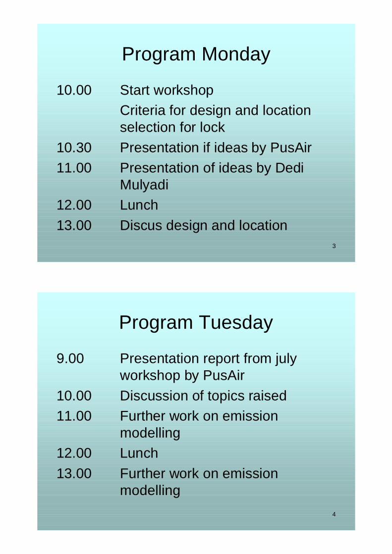
Program Monday
10.00 Start workshopCriteria for design and location selection for lock
10.30 Presentation if ideas by PusAir11.00 Presentation of ideas by Dedi
Mulyadi12.00 Lunch13.00 Discus design and location
4
Program Tuesday
9.00 Presentation report from july workshop by PusAir
10.00 Discussion of topics raised11.00 Further work on emission
modelling12.00 Lunch13.00 Further work on emission
modelling
5
Program Wednesday
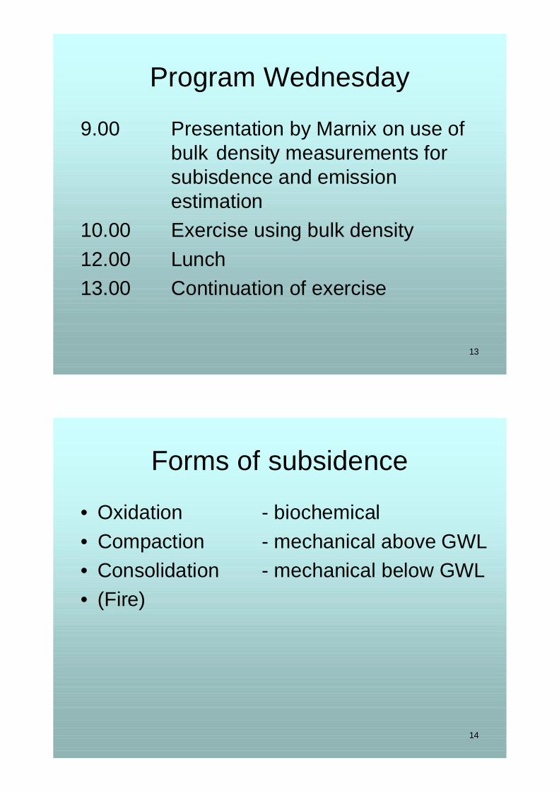
9.00 Presentation by Marnix on use of bulk density measurements for subisdence and emission estimation
10.00 Exercise using bulk density12.00 Lunch13.00 Continuation of exercise
6
Program Thursday
9.00 Presentation by PusAir on Sei Ahas monitoring results
10.00 Analysis of monitoring results and comparison with literature and KFCP
12.00 Lunch13.00 Discussion of Sei Ahas monitoring
and planning of activities
7
Program Monday
10.00 Start workshopCriteria for design and location selection for lock
10.30 Presentation of ideas by PusAir11.00 Presentation of ideas by Dedi
Mulyadi12.00 Lunch13.00 Discus design and location
8
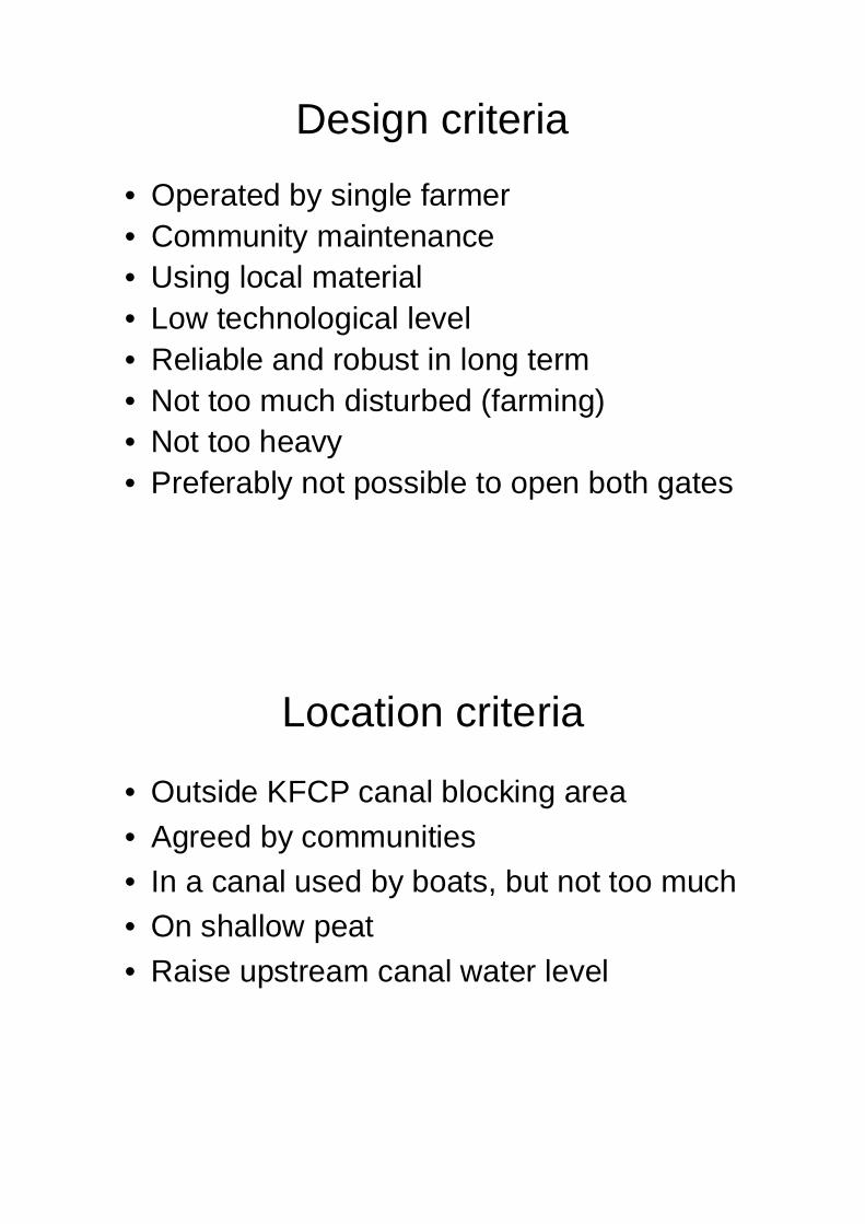
Design criteria
• Operated by single farmer• Community maintenance• Using local material• Low technological level• Reliable and robust in long term• Not too much disturbed (farming)• Not too heavy• Preferably not possible to open both gates
9
Location criteria
• Outside KFCP canal blocking area• Agreed by communities• In a canal used by boats, but not too much• On shallow peat• Raise upstream canal water level
10
Program Tuesday
9.00 Presentation report from july workshop by PusAir
10.00 Discussion of topics raised11.00 Further work on emission
modelling12.00 Lunch13.00 Further work on emission
modelling
11
Read and discus
12
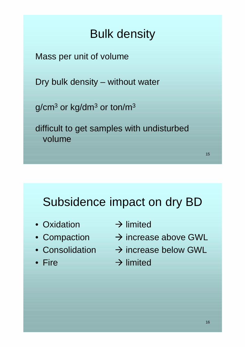
Emission calculation
• Digital Elevation Model• Peat depth measurements peat map• Groundwater depth subsidence rate• % oxiditation CO2 emission
13
Program Wednesday
9.00 Presentation by Marnix on use of bulk density measurements for subisdence and emission estimation
10.00 Exercise using bulk density12.00 Lunch13.00 Continuation of exercise
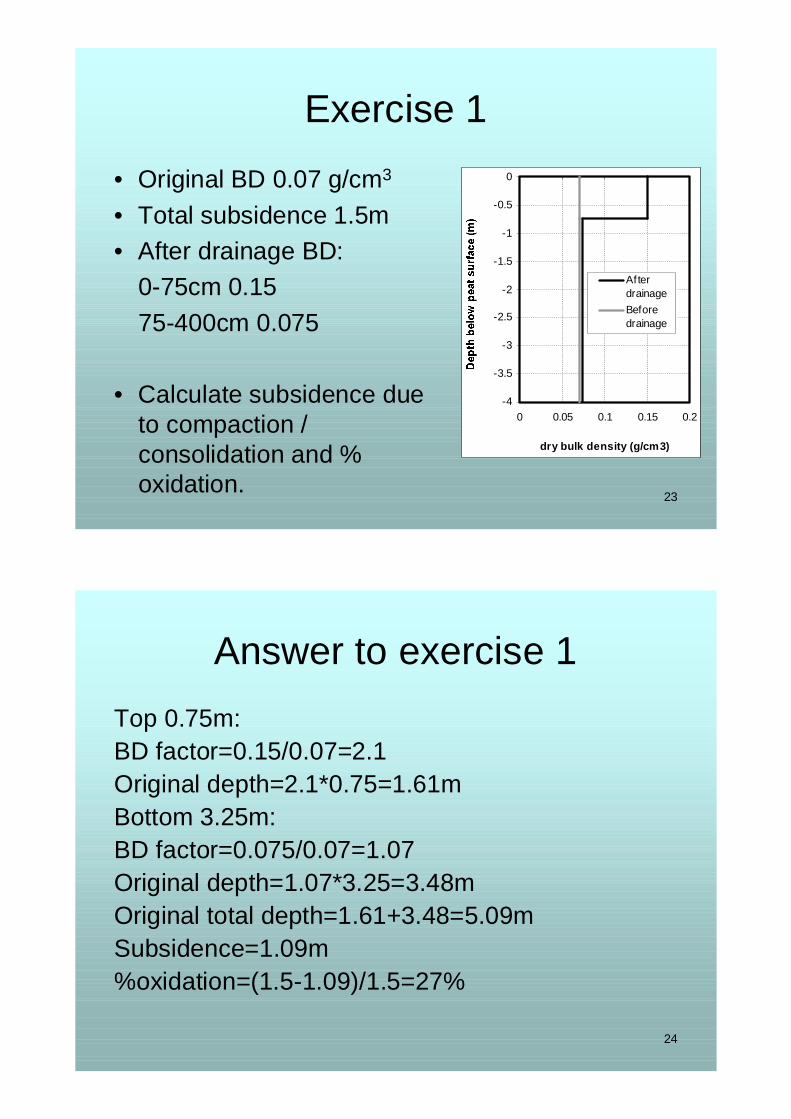
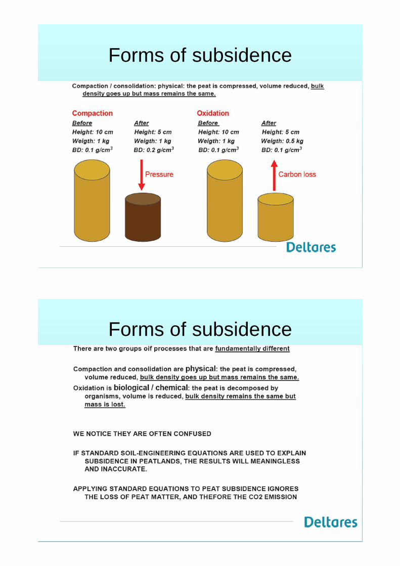
• Calculate subsidence due to compaction / consolidation and % oxidation.
-4
-3.5
-3
-2.5
-2
-1.5
-1
-0.5
0
0 0.05 0.1 0.15 0.2
dry bulk density (g/cm3)
AfterdrainageBeforedrainage
24
Answer to exercise 1Top 0.75m:BD factor=0.15/0.07=2.1Original depth=2.1*0.75=1.61mBottom 3.25m:BD factor=0.075/0.07=1.07Original depth=1.07*3.25=3.48mOriginal total depth=1.61+3.48=5.09mSubsidence=1.09m%oxidation=(1.5-1.09)/1.5=27%
25
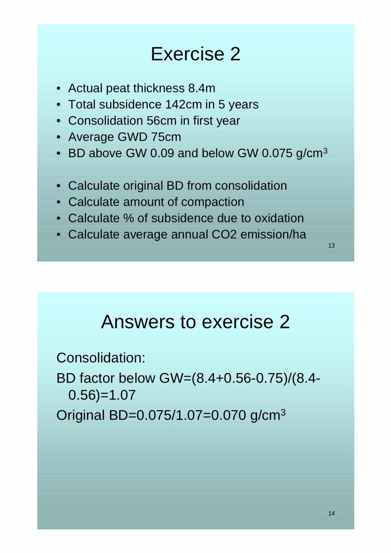
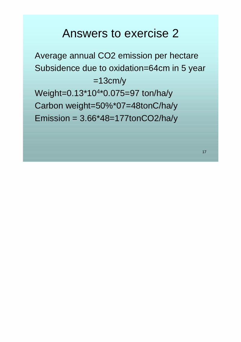
Exercise 2• Actual peat thickness 8.4m• Total subsidence 142cm in 5 years• Consolidation 56cm in first year• Average GWD 75cm• BD above GW 0.09 and below GW 0.075 g/cm3
• Calculate original BD from consolidation• Calculate amount of compaction• Calculate % of subsidence due to oxidation• Calculate average annual CO2 emission/ha
DEGRADATION(Adaptive Strategic for Sustainable Peatland
Management)
Banjarmasin, 8 Oktober 2012
L. Budi Triadi Balai Rawa – Puslitbang SDA
BALITBANG PU
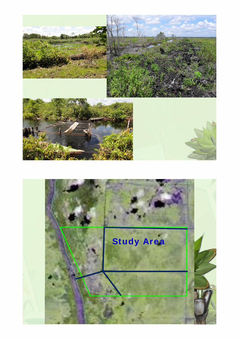
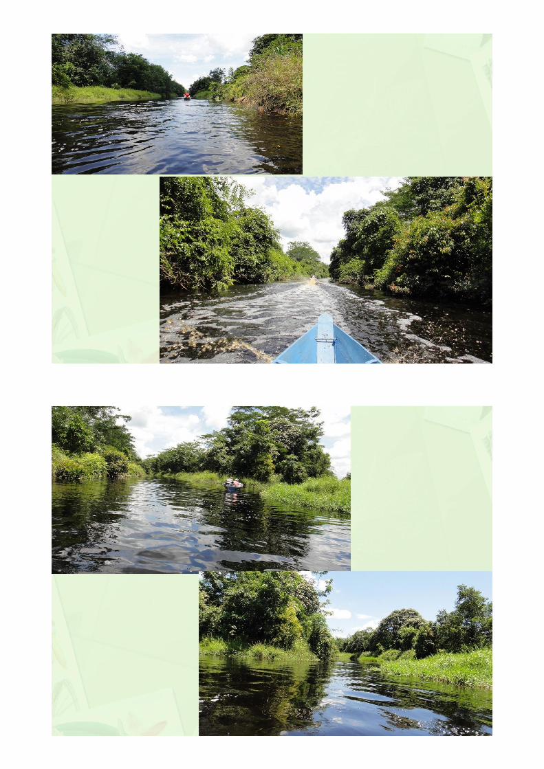
LOCATION OF THE STUDY
• Sei Ahas, Mentangai,Kapuas, Central Kalimantan
• Adaptif ManagementZone
• Peat Depth 3 m
SOURCE :KFCP – HRDM2010
SOURCE :KFCP – HRDM2010
Sei. Ahas
SOURCE :KFCP – HRDM2010
Study Area
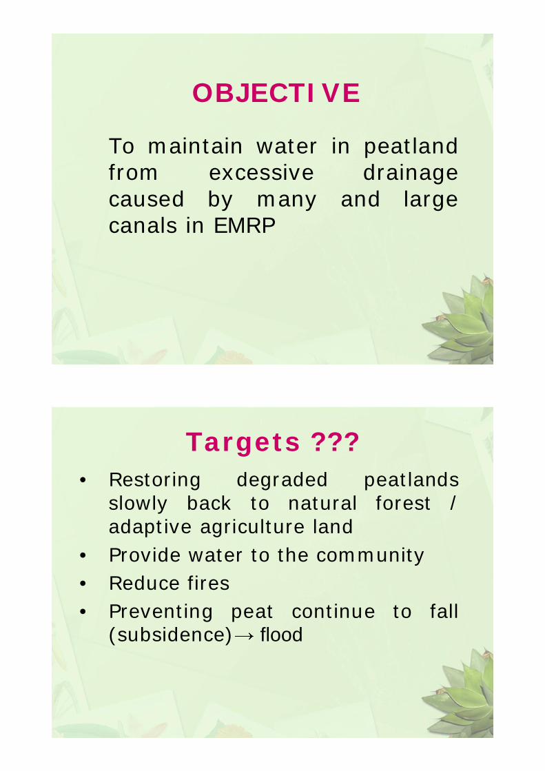
OBJECTIVE
To maintain water in peatlandfrom excessive drainagecaused by many and largecanals in EMRP
Targets ???• Restoring degraded peatlands
slowly back to natural forest /adaptive agriculture land
• Provide water to the community• Reduce fires• Preventing peat continue to fall
(subsidence) flood
Benefit
Farmers can cultivate and growpeatlands that have been opened(degraded) into adaptive farmland
Degraded peat lands back intoforests
HOW ?
To elevate peatland ground water table :
- Build up canal blocking in the canal with no navigation
- Build up canal blocking with ship lock in the canal with navigation
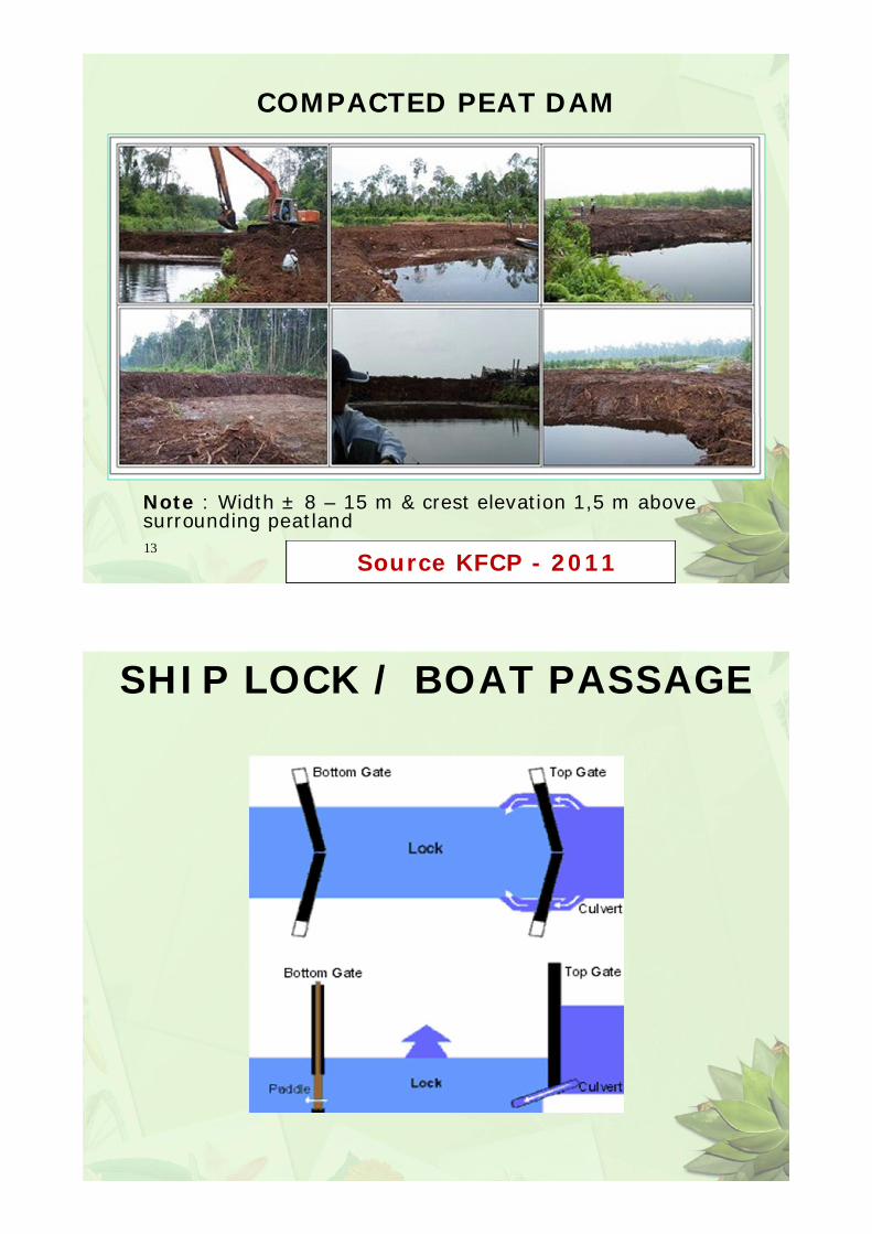
COMPACTED PEAT DAM
13
Note : Width ± 8 – 15 m & crest elevation 1,5 m above surrounding peatland
Source KFCP - 2011
SHIP LOCK / BOAT PASSAGE
HOW IT WORKS ?
BOAT TO BOAT TO UPSTREAM DOWNSTREAM
1–2.Boat enter
8–9.Boat enter
3.Downstram gate is closed
10.Upstream gate is closed
4–5. 11–12.Pond is filling from Pond is emptying from upstream downstream
6.Upstream gate is open
13.Downstram gate is open
7.Boat out of the pond
14.Boat out of the pond
The shiplocks should be built in ways, and with materials, that :
- Allow a single farmer in a small boat to operate it, and a community to maintain.
- It all needs to be very simple and low-tech,
- Using local materials,- Reliable and robust (kuat) in the long term
This probably excludes all concrete and steel type structures such as used in plantations, with a preference for wood and peat as the main building materials (cheap and easily replaced).
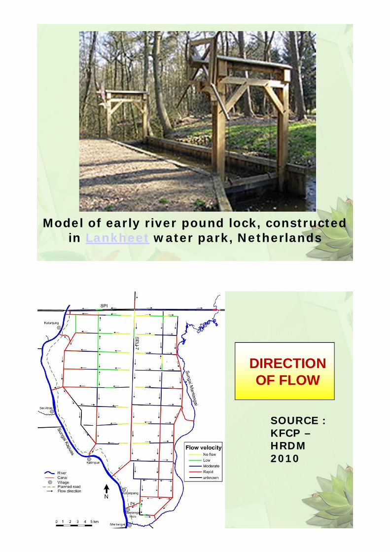
Model of early river pound lock, constructed in Lankheet water park, Netherlands
DIRECTIONOF FLOW
SOURCE :KFCP –HRDM2010
STUDYAREA
PROPOSEDCANALBLOCKING
RESULT OF PUBLIC
CONSULTATION
WM TEST
• Subsidence PolesReduce of
Subsidence
• DipwellsRaise of GWT
• ComputationsReduce of
carbonemission
PEATDEPTHCOUNTOUR
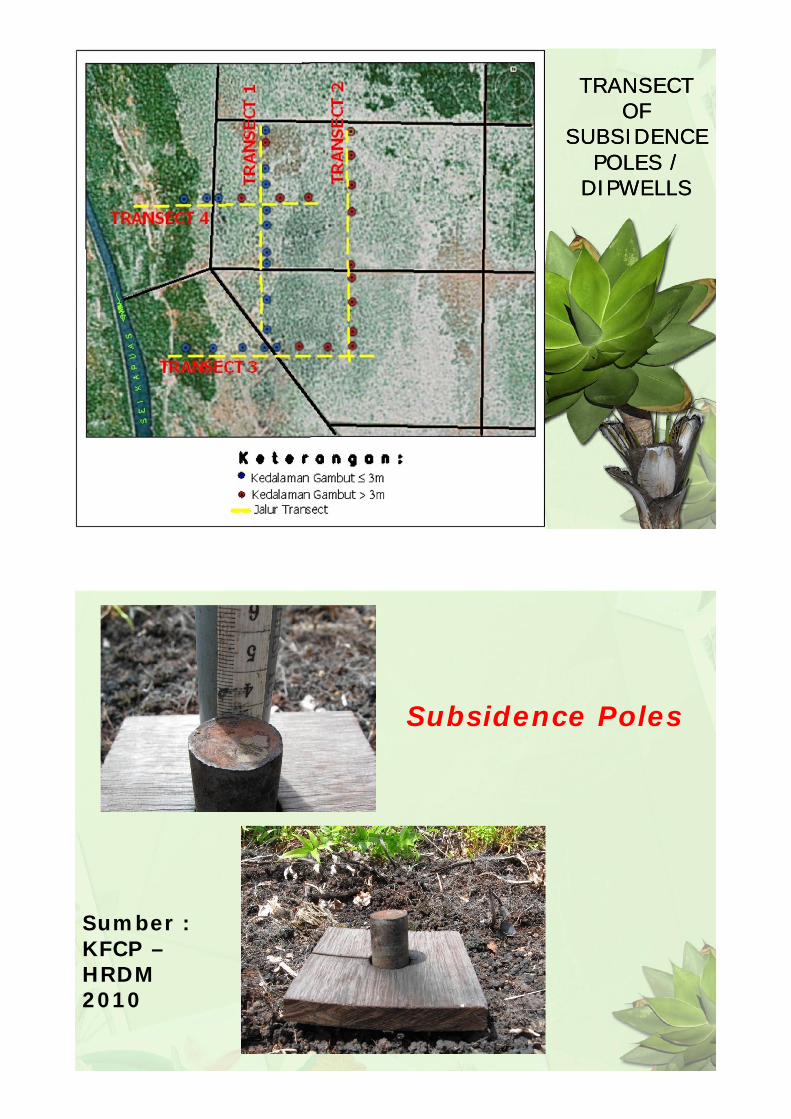
TRANSECT OF
SUBSIDENCEPOLES /
DIPWELLS
TRANSECT OF
SUBSIDENCEPOLES /
DIPWELLS
Subsidence Poles
Sumber :KFCP –HRDM2010
DipwellsSumber :
KFCP – HRDM2010
9 9
5
55
5
6
7
7
6
<8
<7
<7Subsidence poles and Dipwells ( 32 )Staff Gauge ( 9 ), Flow Velocity ( 4 ), Cross SectionRain Gauge ( 1 ) – Year 2013
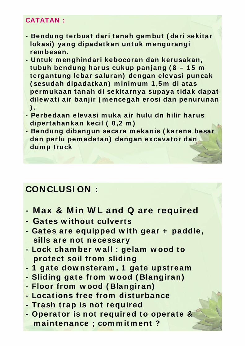
CATATAN :
- Bendung terbuat dari tanah gambut (dari sekitar lokasi) yang dipadatkan untuk mengurangi rembesan.
- Untuk menghindari kebocoran dan kerusakan, tubuh bendung harus cukup panjang (8 – 15 m tergantung lebar saluran) dengan elevasi puncak(sesudah dipadatkan) minimum 1,5m di atas permukaan tanah di sekitarnya supaya tidak dapatdilewati air banjir (mencegah erosi dan penurunan).
- Perbedaan elevasi muka air hulu dn hilir harus dipertahankan kecil ( 0,2 m)
- Bendung dibangun secara mekanis (karena besardan perlu pemadatan) dengan excavator dan dump truck
CONCLUSION :
- Max & Min WL and Q are required- Gates without culverts- Gates are equipped with gear + paddle,
sills are not necessary- Lock chamber wall : gelam wood to
protect soil from sliding- 1 gate downsteram, 1 gate upstream- Sliding gate from wood (Blangiran)- Floor from wood (Blangiran)- Locations free from disturbance- Trash trap is not required- Operator is not required to operate &
maintenance ; commitment ?
- Lock in side channel- Length of canal blocking width of
canal- Automatically close and open gate (not electric one)
- The lock location is at the middle ofside canal
- The material is not steel, concrete or sand, because too heavy
- Foundation is made of cerucuk/ gelam poles
- Build one by one and evaluate each time
- The construction cost should be cheap andlife time less than 7 years
- Land acquisition ? BWS Kal II
-
CANAL LOCK SYSTEM
Canal Lock system is a chamber with gates at both ends, allowed boats to move between different water levels.
Lock chamber with gates at both ends, set the water level in accordance with the purposes: raising the water level to the upstream level and or lowering the water level to the downstream level.
CANAL LOCK COMPONENTS
Ground Paddles
Gate Paddles
Lock Chamber
Gates
Cill
CANAL LOCK STRUCTURES
in terms of water control structures, divided into 3 structure as follows: (1) fully controlled using the culvert on the floor of the structure, (2) controlled by a combination of culverts and gates, (3) controlled entirely by the two gates.
Structure 1 Structure 2 Structure 3
APPLICATION OF CANAL LOCK IN THE PEATLANDS
Lock Chamber built by some Gelam wood driven to mineral soil along the canal walls, with an average diameter of wood required is 15 till 20 cm.
CANAL LOCK IMPLEMENTED IN THE PEATLANDS PLANTATION
Gates often stalled because a lot of woody debris (trash trap is needed, it should be controlled and maintained on a regular basis)
canal floor around gates easily eroded by the waterfall (the floor needs to be protected by wooden material)
Landslides and erosion around the gates, locks canal should be built in a location that has not been disturbed.
CANAL LOCK IMPLEMENTED IN THE PEATLANDS PLANTATION
CANAL LOCK DESIGN FOR SEI AHAS
• The type of canal locks structure selected in accordance with the conditions of peat that is controlled entirely from both gates (without culverts), and each gates equipped with cill.
• Cill (equipped with gears and gate paddles) are made of steel plate with size adjusted to the needs.
• Lock Chamber maximum sized 10x2 m, enough to pass a kelotok.• With a width of 2 m, each gate will be enough with one door only.• Gate made from local wood that is water resistance such as "blangiran".• Lock Chamber covered by some gelam wood with a diameter of 15-20 cm, pushed
to the mineral soil minimum 2 m, along the canal wall around the structure.• The floor around the gates covered by wood beams that water resistant such as
blangiran to protect the floor from the scouring of water when gates opened and closed.
• To reduce erosion around the structure of the canal lock, the location should be selected that has not been disturbed.
• Required the trash or debris trapper to anticipate stuck gates.• Required the operator to operate the canal lock and to maintain it.
Design criteria
• Operated by single farmer• Community maintenance• Using local material• Low technological level• Reliable and robust in long term• Not too much disturbed (farming)• Not too heavy• Preferably not possible to open both gates
Location criteria
• Outside KFCP canal blocking area• Agreed by communities• In a canal used by boats, but not too much• On shallow peat• Raise upstream canal water level
1
Program Wednesday
9.00 Presentation by Marnix on use of bulk density measurements for subisdence and emission estimation
10.00 Exercise using bulk density12.00 Lunch13.00 Continuation of exercise
• Calculate subsidence due to compaction / consolidation and % oxidation.
-4
-3.5
-3
-2.5
-2
-1.5
-1
-0.5
0
0 0.05 0.1 0.15 0.2
dry bulk density (g/cm3)
AfterdrainageBeforedrainage
12
Answer to exercise 1Top 0.75m:BD factor=0.15/0.07=2.1Original depth=2.1*0.75=1.61mBottom 3.25m:BD factor=0.075/0.07=1.07Original depth=1.07*3.25=3.48mOriginal total depth=1.61+3.48=5.09mSubsidence=1.09m%oxidation=(1.5-1.09)/1.5=27%
13
Exercise 2• Actual peat thickness 8.4m• Total subsidence 142cm in 5 years• Consolidation 56cm in first year• Average GWD 75cm• BD above GW 0.09 and below GW 0.075 g/cm3
• Calculate original BD from consolidation• Calculate amount of compaction• Calculate % of subsidence due to oxidation• Calculate average annual CO2 emission/ha