36
COMPONENT CATALOGUE FOR MULTI-STOREY RESIDENTIAL BUILDINGS MADE FOR BUILDING BUILT FOR LIVING

COMP ONEN T CATA LO GUE FOR
MULT I - S TOR E Y R E S IDENT I A L B U ILD IN G S
M A D E f O R B U I L D I N Gb u i l t f o r l i v i n g

© KLH Massivholz GmbH
Publisher and responsible for the content: KLH Massivholz GmbHVersion: 01/2012, Component Catalogue for Multi-storey Residential Buildings
The content of this brochure is intellectual property of the company and is protected by copyright. The statements are recommendations and proposals only; a liability on the part of the publisher is excluded. Any type of reproduction is strictly forbidden and only permitted after written approval of the publisher.
I M P R I N T

gener al PrinciPles 04
construction systems 07
01 floor Pl an t yPes for KlH – bs 01 08
02 floor Pl an t yPes for KlH – bs 02 10
03 floor Pl an t yPes for KlH – bs 03 11
04 floor Pl an t yPes for KlH – bs 04 12
05 floor Pl an t yPes for KlH – bs 05 13
06 deta il KlH – bs 01-1 14
07 deta il KlH – bs 01-2 15
08 deta il KlH – bs 01-3 16
09 deta il KlH – bs 01- 4 17
10 deta il KlH – bs 01-5 18
11 deta il KlH – bs 01- 6 19
12 deta il KlH – bs 01-7 20
13 deta il KlH – bs 01- 8 21
14 deta il KlH – bs 02-1 22
15 deta il KlH – bs 03 -1 23
16 deta il KlH – bs 03 -2 24
17 deta il KlH – bs 03 -3 25
18 deta il KlH – bs 04 -1 26
19 deta il KlH – bs 05 -1 27
20 deta il KlH – bs 05 -2 28
21 deta il KlH – bs 05 -3 29
0 1
C O N T E N T

Numerous residential building projects have already
been built successfully with KLH solid wood panels –
from detached houses to multi-storey blocks of flats and
even the currently highest solid wood building in the
world with 8 KLH storeys, located in London.
Besides the static aspects and requirements of construc-
tional physics, the main focus in residential building is
on noise protection.
Noise protection requirements vary from one building
project to another. Detached houses usually do not have
any special indoor requirements in this regard, while
partition ceilings and partition walls in multi-storey
buildings have high requirements. In addition, many
European countries have their own, individual, national
requirements.
Currently, noise protection requirements are the highest
in Scandinavian countries, and they can only be met with
complex constructions. Southern-European countries,
on the other hand, allow simpler, more cost-effective
wall and ceiling structures that fully meet the local noise
protection regulations.
This Construction Component Catalogue includes
a number of designs and certif ied components with
their respective measured values. The data was partly
measured in laboratories, partly on completed buildings
or especially set-up test constructions.
The positive feedback from satisfied residents shows that
the requirements concerning “noise protection in solid
wood construction” have been met successfully. However,
we still recommend contracting the services of an expert
on building physics.
multi -storeyresidentialBUILDINGS
0 2
I N T R O D U C T I O N

v O R w O R T
KLH

NOISE PROTECTION
This Construction Component Catalogue contains a
number of certified component structures with their
relevant measured values. Many of the measurements
were made in laboratories (construction components
without side paths), most of them, however, were made
on completed buildings. Apart from direct sound paths
through individual building components, the side paths
are also of importance.
The stated noise protection levels can only be attained in
combination with the suggested sound-technical decou-
pling (e.g. installation of elastic bearings between KLH
wall and ceiling components) as well as facing form-
work elements, for example. The detailed solutions are
intended to be recommendations by the manufacturer.
The construction suggestions included should illustrate
the constructional principle of the individual building
methods. Please keep in mind that changes to materi-
als and/or thicknesses of layers will lead to changes in
noise protection values. Nearly all construction projects
are unique in some aspects. Therefore, it is recommen-
ded that the services of an expert in building physics
for detailed planning be contracted, if the requirements
concerning noise and/or heat insulation, for example,
are very high.
STATICS AND KLH PANEL THICKNESSES
The panel thicknesses of the individual building compo-
nents (wall, ceiling, roof) must be determined according
to the static requirements. For normal room sizes in re-
sidential buildings we can assume walls from 94 to 128 mm
(e.g. load-bearing interior wall on the ground floor of a
4-storey residential building) and ceilings from about
140 to 182 mm of panel thickness. A thorough static
analysis is absolutely necessary.
Apart from the def lection of vertical loads, the safe
def lection of horizontal forces must be kept in mind.
Depending on the relevant location, there might be
earthquake forces in addition to wind forces. The
reinforcement of buildings in wood construction is an
essential part of static calculations. In this regard the KLH
solid wood panels are advantageous, while small-sized
panel structures often need tension anchoring for foun-
dations and also between storeys, leading to a worse
sound-technical situation. When using large-sized
solid wood panels, even wall areas with door or window
openings can be used for load-bearing purposes. The
lever arms of the walls are increased considerably, and
tension anchorage can often be avoided.
general PRINCIPLES
0 4
G E N E R A L P R I N C I P L E S

Sound measurement in completed buildings also takes
connections (angle brackets, screw connections) into
consideration.
Therefore, the results of measurements also include
the effects of screw connections in the areas of elastic
bearings.
fIRE RESISTANCE
Proof has to be provided for the load-bearing capacity
of each component in case of a fire (“R” criterion) in the
form of a static calculation. The European Technical
Assessment ETA-06/0138 clearly defines the burn-off
rates for KLH components. Proof is based on the residual
cross-sections according to Eurocode 5.
If the surfaces of KLH solid wood panels are protected
from fire in the beginning, e.g. by drywall fire protection
boards, then the failure time of panel layers may be
taken into account for dimensioning.
Multi-layer KLH solid wood panels also allow the con-
struction of components with high fire-resistance ratings,
and proof can be provided for R90 or R120, for example.
This way, 5-layer ceiling panels already reach R60
without any additional measures or even R90 if the
panel thickness is sufficient, making visible-grain con-
structions with high fire resistance easy to realise.
If necessary, panel layers or higher panel thickness can
further improve the fire resistance of any construction.
For wall components, the required fire resistance is
usually achieved with panel layers, since, for example,
with 3-layer KLH wall panels you can merely reach a
maximum fire resistance rating of R30.
It also needs to be taken into account that load-bearing
interior walls will usually burn down on both sides. For
exterior walls, special attention must be paid to pillars
between windows and doors.
INSTALLATIONS
For most of the building projects, installations were
realised the usual way.
Fillings and suspended ceilings were used for cable
routing. In load-bearing interior and exterior walls, vertical
milled ducts were made (keep a minimum distance of
10 cm from the panel edge and only mill in the direction
of the top layer orientation).
As far as “wall ends” are concerned (e.g. next to doors), it
has to be taken into account that the static load-bearing
capacity may be reduced by up to 30% in case of a large
number of cabling. A static analysis has to be made in
individual cases.
As regards partition walls in apartments, any such points
with reduced load-bearing capacities should not be
positioned opposite each other, but shifted by approx.
1 m, for sound reasons. It would be even better to avoid
installations in partition components altogether or to
keep them to an absolute minimum.
In case of a large number of cables, as well as water
pipes and sanitary installations, a curtain wall construc-
tion should always be made. In case of water piping,
sufficient sound decoupling has to be ensured.
0 5
G E N E R A L P R I N C I P L E S

BUILDING PHYSICS
A wall should have a structure that is open for vapour
diffusion in order to ensure that the wall absorbs moisture
and dispenses it towards the inside, if necessary. This
way you avoid the formation of condensation inside a
wall structure and ensure a healthy and pleasant room
climate.
Another basic principle is the layered wall structure.
The KLH construction forms the load-bearing, reinforcing
and room-closing core. If the joints are designed
carefully, they can be regarded as a windproof layer. It
is essential to pay attention to the transition to concrete
parts – sometimes they are carried out imprecisely.
On the outside of the solid wood panel, a convection
barrier or vapour retarder is applied, depending on the
type of insulation material and façade structure. This
layer must be put across the entire surface. Joints have
to be glued tight. The layer has to be connected to the
adjacent building components such as concrete/cellar or
windows/doors.
Constructions made of cross-laminated timber (“KLH”)
may even be constructed without an additional flow-tight
layer to the outside, if the joint sealing (joints between
wall/ceiling, ceiling/wall, wall/wall, wall/window or
doors, ceiling joints, penetrations, etc.) is carried out
carefully. This would require wall structures open for
diffusion, as well as the use of a 5-layer KLH panel in
non-visible quality (NSI) or a 3-layer panel in visible
industrial quality (ISI).
Careful realisation and appropriate positioning of joint
tapes have to be ensured. It is essential to have precise
connections and transitions to concrete parts. The design
of sill plates sealed to the concrete structure (suitable
adhesive tape) is regarded as the safest variant. Special
attention must also be paid to protruding KLH compo-
nents running from the “warm” inside area to the “cold”
outside area (e.g. protruding ceiling and roof panels). The
joints between the individual KLH elements (e.g. shiplap
edge or covering board connection between lying
elements) in the area of the sealing level must be sealed
appropriately and permanently.
Subsequently, the insulation level and the façade are
applied. If the insulation material is stiff enough, it can
be fastened directly onto the walls (without intermediate
brackets). The fastening will depend on the selected
façade material.
fAÇADE
Apart from timber façades, rendered, slab and metal
façades are also possible. The entire wall structure must
be adjusted to the façade type. The building-physical
requirements are decisive. The tighter the material of
the outer shell, the more important the installation of a
back-ventilation layer or tight vapour retarder or barrier.
Static calculations must also be made for the wall and
roof structures in each individual case.
0 6
G E N E R A L P R I N C I P L E S

OvERvIEw Of INDIvIDUAL BUILDING SYSTEMS (BS 01-05)
Pas s i v e house s e t t i ng “A m Müh lweg ”, V i enna
Res i den t i a l bu i l d ing “Spö t t e l g as se”, V i enna
A lp ine ho t e l “A mmer wa ld”, Reu t t e
“ Town counc i l s en i o r c i t i zens ’ home”, Judenburg
Te r r aced house e s t a t e “B i e l eweg ”, Ludesch
KLH – BS 01double-leaf aPartment Partition
KLH – BS 02single-leaf aPartment Partition
KLH – BS 03modular construction
KLH – BS 04attic conversion
KLH – BS 05terraced House
0 7
B U I L D I N G S Y S T E M S
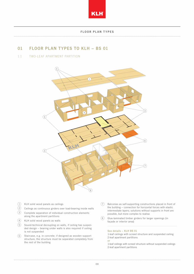
01 fLOOR PLAN TYPES TO KLH – BS 01
1.1 t wo -leaf aPartment Partition
Ceilings as continuous girders over load-bearing inside walls
KLH solid wood panels as walls
Sound-technical decoupling on walls, if ceiling has suspen-ded design – bearing under walls is also required if ceiling is not suspended
Complete separation of individual construction elements along the apartment partitions
See details – KLH BS 011-leaf ceilings with screed structure and suspended ceiling2-leaf apartment partitionsor1-leaf ceilings with screed structure without suspended ceilings2-leaf apartment partitions
5
5
8
7
6
4
4
3
3
1
2
2
2
KLH solid wood panels as ceilings1
Staircase, e.g. in concrete; if designed as wooden support structure, the structure must be separated completely from the rest of the building
Balconies as self-supporting constructions placed in front of the building – connection for horizontal forces with elastic intermediate layers; solutions without supports in front are possible, but more complex to realise
Glue- laminated timber girders for larger openings (in façade or interior area)
8
7
6
f L O O R P L A N T Y P E S
0 8

1.2 t wo -leaf aPartment Partition (variant)
Ceilings as continuous girders over load-bearing inside walls
KLH solid wood panels as ceilings
KLH solid wood panels as walls
Complete separation of individual construction elements along the apartment partitions
Staircase, e.g. in concrete; if designed as wooden support structure, the structure must be separated completely from the rest of the building
Balconies as self-supporting constructions placed in front of the building – connection for horizontal forces with elas-tic intermediate layers; solutions without supports in front are possible, but more complex to build
Glue- laminated timber girders for larger openings (in façade or interior area)
See details – KLH BS 011-leaf ceilings with screed structure and suspended ceiling2-leaf apartment partitionsor1-leaf ceilings with screed structure without suspended ceilings2-leaf apartment partitions
8
7
6
4
3
1
2
Sound-technical decoupling on walls, if ceiling has suspen-ded design – bearing under walls is also required if ceiling is not suspended
5
5
43
1
8
7
2
2
6
f L O O R P L A N T Y P E S
0 9

See details – KLH BS 021-leaf ceilings with screed structure and suspended ceiling1-leaf apartment partition with 2 facing formwork elements
Ceilings as continuous girders over load-bearing inside walls
KLH solid wood panels as walls
Ceilings as continuous girders also across apartment parti -tions – longitudinal joints in “zero momentum point”
Staircase and/or access corridors as separate building units – e.g. concrete constructions
Balconies as self-supporting constructions placed in front of the building – connection for horizontal forces with elastic intermediate layers
5
7
7
6
6
4
4
4
3
3
1
1
2
2
2
02 fLOOR PLAN TYPES TO KLH – BS 02
2.1 single-leaf aPartment Partition
KLH solid wood panels as ceiling
No sound-technical bearing required – neither under nor over ceilings
5
1 0
f L O O R P L A N T Y P E S

03 fLOOR PLAN TYPES TO KLH – BS 03
3.1 modular construction
87
6
4
3
1
1
2
5
See details – KLH BS 032-leaf walls and ceilings (also possible for prefabricated room modules)
Ceiling and floor panels as one-span girders between load-bearing walls
Sound-technical bearing between modules
Bearing of modules on strip and point foundations
KLH solid wood panels as walls
KLH solid wood panels as f loor and ceiling panels
Completely opened façade areas are possible
7
6
5
4
1
2
The building units can be manipulated as prefabricated modules by way of simple steel structures
3
Balconies can be integrated into load-bearing structure of the relevant module, since the modules are decoupled
8
1 1
f L O O R P L A N T Y P E S

04 fLOOR PLAN TYPES TO KLH – BS 04
4.1 at tic conversion
5
6
4
3
1
See details – KLH BS 041-leaf partition with facing formwork on both sides (especially for at tic superstructures on old buildings)
Separation of roof panels at the apartment partition
Supporting walls in longitudinal and transverse directions or steel frame
Separation of wall panels at apartment partitionKLH solid wood panels as ceiling and roof panels
KLH solid wood panels as walls
Load-bearing ef fect, e.g. as freely supporting shear wall between 2 bearings
5
6
4
3
1
2
2
1 2
f L O O R P L A N T Y P E S

See details – KLH BS 052-leaf partition (no special sound-related requirements on the ceiling for terraced house types)
Gable walls of KLH panels
ATTIC
UPPER fLOOR
GROUND fLOOR
Attic, e.g. conventional raf ter construction on purlins, wall plate/eaves purlin of KLH panels
Inner load-bearing system as skeleton structure
Load-bearing inside and outside walls of KLH panels
Complete separation of both houses in the area of the partition
Inner load-bearing structure combined of laminated timber and KLH panels
Normally no elastic bearing of ceilings is required, since there are no special noise protection requirements inside the apartment (exception: request by building owner)
05 fLOOR PLAN TYPES TO KLH – BS 05
5.1 terraced House
8
7
6
5
5
4
3
1
2
6
1
2 3
3
8
7
Ceilings of KLH panels – designed as continuous girder is optimal
4
1 3
f L O O R P L A N T Y P E S

APARTMENT 3
APARTMENT 2
APARTMENT 1
APARTMENT 4
Apartment partition ceiling: wTD 01
Ceil ing s tructure5 to 7 cm screedScreed film3 cm TSDP6 cm filling, unboundTrickle protection (if necessary)KLH ceiling panelSuspended ceiling
DnT,w > 55 (-3;-9) dBR’w > 60 dBL’nT,w < 46 (2) dB
wall s tructure 15 mm GKF KLH wall panelFlow-tight layer60 mm Heralan TW12.5 mm GK plasterboard60 mm Heralan TWKLH wall panel15 mm GKF
Apar tment par t i t ion: wTw 2s 06
DnT,w > 55 (-5;-14) dB Rw > 64 (-3;-10) dB
9
8
7
4
3
1
KLH wall panel
Floor structure
Apartment partition
Gypsum plasterboard facing
Suspended ceiling (approx. 7 cm air space with cavity damping)
Elastic bearing
Screw connection according to statics
KLH ceiling panel
Install joint tape
5
9
8
7
6
4
3
1
2
2
5
6
6
06 DETAIL KLH – BS 01-1
6.1 nodal Point Partition ceiling – aPartment Partition
1 4
D E T A I L

Apartment partition ceiling: wTD 01
Ceil ing s tructure5 to 7 cm screedScreed film3 cm TSDP6 cm filling, unboundTrickle protection (if necessary)KLH ceiling panelSuspended ceiling
DnT,w > 55 (-3;-9) dBR’w > 60 dBL’nT,w < 46 (2) dB
5
9
8
7 6
4
3
1
KLH wall panel
Floor structure
Elastic bearing for noise protection
Suspended ceiling (approx. 7 cm air space with cavity damping)
Screw connection according to statics
KLH ceiling panel
Joint tape
BMF angle bracket for shear forces as well as minor tensile forces
Gypsum plasterboard facing
5
9
8
7
6
4
3
1
2
07 DETAIL KLH – BS 01-2
7.1 nodal Point Partition ceiling – load -bearing interior wall
2
1 5
D E T A I L

APARTMENT 1
APARTMENT 2
Joint
Insert insulation tape on site (if façade is prefabricated)
Plaster base and plaster permeable for dif fusion
KLH ceiling panel
KLH wall panel
Sealing tape to connect individual convection barriers
Angled screw connection for “curtain façade” depending on static requirements
Convection barrier (vapour tightness to be adjusted to fur ther wall structure)
Install insulation tape on site
Insert sealing tape or glue tight on the inside
2- layer heat insulation (approx. 2 x 14 cm for passive house)
Assembly for prefabricated wallWith this design, a passive house level was achieved for the “Am Mühlweg” building project in Vienna (air tightness, insulation rating)
Fold in convection barrier
08 DETAIL KLH – BS 01-3
8.1 nodal Point Partition ceiling – exterior wall, Prefabricated
5
5
5
8
8
9
9
10
10
11
11
12
12
7
7
6
6
6
4
4
4
3
3
1
1
2
2
Apartment partition ceiling: wTD 01
Ceil ing s tructure5 to 7 cm screedScreed film3 cm TSDP6 cm filling, unboundTrickle protection (if necessary)KLH ceiling panelSuspended ceiling
DnT,w > 55 (-3;-9) dBR’w > 60 dBL’nT,w < 46 (2) dB
1 6
D E T A I L

APARTMENT 1
APARTMENT 2
APARTMENT 1(ROOf TERR ACE)
09 DETAIL KLH – BS 01-4
9.1 connection exterior wall – ceiling witH roof
terrace included
5
8
10
11
12
16
13
17
7
6
4
3
3
1
9
Back-ventilated façade
Elastic bearing
Screw connection according to statics
BMF angle bracket for shear transmission
Put up vapour barrier in wall area
KLH roof panel
KLH wall panel
Convection barrier
Suspended ceiling (approx. 7 cm air space with cavity damping)
Plasterboard facing
5
8
9
10
7
6
4
3
1
2
2
14
18
Flagging
Gravel f illing
Slope wedge insulation
Heat insulation
Footstep sound insulation board
Vapour barrier (and makeshif t sealing during building stage)
Insulation boards to protect the sealing level
Moisture sealing (water-bearing layer)
11
12
16
13
17
14
18
15
15
R’w = 51(-2;-7) dB
Exterior wall: Aw 03
wall s tructureFaçade – wood (board, planks – sealed)Back-ventilation layer(Bat tens screwed tight with KLH)2 x 80 mm rock wool across entire surface (Heralan FP)KLH 3s 94 mm15 mm GKF
1 7
D E T A I L

APARTMENT 1
APARTMENT 2
APARTMENT 1 (ROOf TERR ACE)
FlaggingGravel f illingInsulation boards(Protection for sealing)Sealing layerSlope wedge insulationHeat insulationTSDPVapour barrierKLH ceiling panelSuspended ceiling
flat roof structure: outside
FlooringScreed on screed filmTSDPPerlite f illing to level height dif ferences and allow barrier-free access to the roof terrace
floor structure: inside
10 DETAIL KLH – BS 01-5
10.1 floor structure, roof terrace witH connection, terrace door
5
88 9
10
11
12
7
7
6
6
4
3
1
2
Back-ventilated wood façade
Close sealing level
Screw connection according to statics (own weight of door and window elements)
False f loor edge
Subframe
Metal cover plate
KLH wall panel
KLH ceiling panel
5
8
7
6
4
3
1
2
Outside f lat roof structure
Suspended ceiling
BMF angle bracket10
11
12
Inside f loor structure9
1 8
D E T A I L

11 DETAIL KLH – BS 01-6
11.1 nodal Point aPartment Partition – ceiling Partition
KlH visible
5
8
7
4
3
1
1
BMF angle bracket
KLH wall panel
3s KLH wall panel
KLH ceiling panel
Elastic bearing
Apartment partition
Floor structure
Screw connection according to statics
5
8
7
6
4
3
1
2
2
6
6
Apartment partition ceiling: wTD 05
Ceil ing s tructureScreedTSDPFillingSof t f ibre panelTrickle protection (if necessary)KLH ceiling panel – without suspended ceiling
DnT,w > ?? dBR’w > ?? dBL’nT,w < 42 (1) dB
Apar tment par t i t ion: wTw 2s 06
wall s tructure15 mm GKF KLH wall panel60 mm Heralan TW12.5 mm GK plasterboard60 mm Heralan TW Wind sealingKLH wall panel15 mm GKF
DnT,w > 55 (-5;-14) dBRw > 64 (-3;-10) dB
1 9
D E T A I L

12 DETAIL KLH – BS 01-7
12.1 nodal Point ceiling – load -bearing interior wall / variant witH
reduced noise Protection requirements on tHe ceiling
KLH wall panel
Gypsum plasterboard facing
KLH ceiling panel
Suspended cei l ing (2 cm air, 8 cm mineral wool, 1.5 cm plas terboard)
Joint tape
Raf ter-purling anchor for shear transmission
Floor structure
Screw connection according to statics
Elastic bearing
Apartment partition ceiling: wTD 06
Ceil ing s tructure PVC flooring6 cm screedFilm0.6 cm sof t f ibre panelKLH ceiling panelSuspended ceiling
R’w > 60 (-1,-6) dBL’nT,w < 50 (-1) dB(with PVC flooring 48 (0) dB)
5
5
5
8
8
9
9
7
7
6
6
4
4
3
3
3
1
1
2
2
2 0
D E T A I L
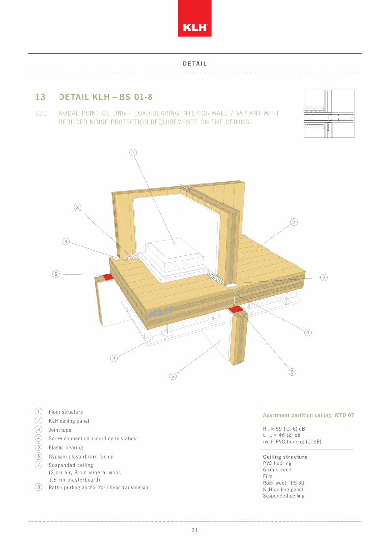
Apartment partition ceiling: wTD 07
Ceil ing s tructurePVC flooring6 cm screedFilmRock wool TPS 30KLH ceiling panelSuspended ceiling
R’w > 59 (-1,-6) dBL’nT,w < 46 (2) dB(with PVC flooring (1) dB)
13 DETAIL KLH – BS 01-8
13.1 nodal Point ceiling – load -bearing interior wall / variant witH
reduced noise Protection requirements on tHe ceiling
5
5
8
7
6
4
3
3
1
Gypsum plasterboard facing
KLH ceiling panel
Suspended cei l ing (2 cm air, 8 cm mineral wool, 1.5 cm plas terboard)
Joint tape
Raf ter-purling anchor for shear transmission
Floor structure
Screw connection according to statics
Elastic bearing5
8
7
6
4
3
1
2
2
2 1
D E T A I L

Flow-tight layer
Elastic base tape
Connection according to statics
KLH wall panel according to static requirements
Stand-alone facing formwork in front of the KLH panel
Metal angle bracket for fastening of facing formwork on individual points
Suspended ceiling
5s KLH ceiling panel
Floor structure
TPS 25/22
Facing formwork, self-supporting:12.5 GK plasterboard panel25 mm Heraklith BM15 mm GKF panel, all 3 layers glued to one package, stand-alone in front of KLH wall
Apartment partition ceiling: wTD 01
Ceil ing s tructure5 to 7 cm screedScreed film3 cm TSDP6 cm filling, unbound trickle protection (if necessary)KLH ceiling panelSuspended ceiling
DnT,w > 55 (-3;-9) dB R’w > 60 dBL’nT,w < 46 (2) dB
wall s tructureFacing formwork, self-supportingTPS 25/22KLH wall panelFlow-tight layerTPS 25/22Facing formwork, self-supporting
Apar tment par t i t ion: wTw 1s xx t
DnT,w > 59 (-1;-7) dBR’w > 60 (-2;-8) dBRw > 63 (-3;-9) dBREI 90 on both sides
14 DETAIL KLH – BS 02-1
14.1 nodal Point Partition ceiling – aPartment Partition
5
5
8
9
9
9
10
10
11
11
7
6
6
6
4
4
3
3
1
1
2
2
8
7
2 2
D E T A I L
APARTMENT 3
APARTMENT 1
APARTMENT 4
APARTMENT 2
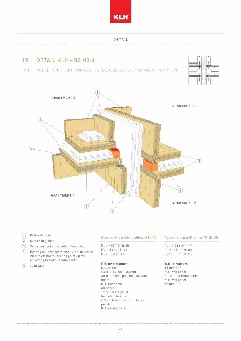
15 DETAIL KLH – BS 03 -1
15.1 nodal Point Partition ceiling (double-leaf) – aPartment Partition
5
4
3
1
1
KLH wall panel
Bearing of upper room module on individual 20 mm elastomer bearing points (area according to static requirements)
KLH ceiling panel
Screw connection according to statics
Joint tape
Apartment partition ceiling: wTD 03
Ceiling structureDry screed(12.5 + 15 mm Feracell)35 mm footstep sound insulation boardKLH floor panelAir space12.5 mm GK panelInsulation boards(12 cm total distance between KLH panels)KLH ceiling panel
DnT,w = 57 (-1;-5) dB R’w = 58 (-1;-5) dBL’nT,w = 43 (7) dB
wall s tructure15 mm GKF KLH wall panel2 x 60 mm Heralan FPKLH wall panel15 mm GKF
Apar tment par t i t ion: wTw 2s 05
DnT,w > 64 (-3;-9) dB R’w > 65 (-3;-9) dB Rw > 60 (-4;-12) dB
5
4
3
1
2
2
2
2 3
D E T A I L

MODULE 1
MODULE 2
APARTMENT 1
APARTMENT 2
16 DETAIL KLH – BS 03 -2
16.1 connection of Partition ceiling (2-leaf) – exterior wall
5
8
9
7
6
4
3
3
1
Heat insulation
Wind proofing
Back-ventilated façade
2- layer heat insulation
8
9
7
6
Gypsum plasterboard5Install insulation tape on site (if room modules are prefabricated)
Point bearing for upper room module
KLH panels
Screw connection according to static requirements
4
3
1
2
2
Exterior wall: Aw 03
R’w = 51(-2;-7) dB
Apartment partition ceiling: wTD 03
DnT,w = 57 (-1;-5) dB R’w = 58 (-1;-5) dBL’nT,w = 43 (7) dB
2 4
D E T A I L

APARTMENT 1
APARTMENT 2
APARTMENT 2
APARTMENT 1
ROOf TERR ACE Of APARTMENT 2 ROOf TERR ACE Of
APARTMENT 1
various development s tages
17 DETAIL KLH – BS 03 -3
17.1 examPle of roof terrace design
8
7
6
Insulation level (slope wedge insulation)
Mind joint closures – do not produce sound bridges
Vapour barrier
Raise vapour barrier
8
7
6
5
5
4
3
1
Make sure of suf f icient sound insulation to adjacent module in case of window instal -lations – only weaken KLH panel slightly
E.g. wooden grid in gravel bed, below insula-tion boards as protection for sealing levels
Connect moisture sealing to window element
Close the sealing level (vapour barrier from roof structure with window level)
4
3
1
2
2
Apar tment par t i t ion: wTw 2s 05
Apartment partition ceiling: wTD 03
DnT,w = 57 (-1;-5) dB R’w = 58 (-1;-5) dBL’nT,w = 43 (7) dB
DnT,w > 64 (-3;-9) dB R’w > 65 (-3;-9) dB Rw > 60 (-4;-12) dB
2 5
D E T A I L

APARTMENT 1
APARTMENT 2
Apar tment par t i t ion: wTw 1s vs
wall s tructure 15 mm GKF 60 mm Heralan TW on metal post or lath separateAir spaceKLH 3s 94 mmAir space60 mm Heralan TW on metal post or lath separate15 mm GKF
Rw > 58 (-3;-11) dB
Roof s tructureRoof membrane – PVC800 mm Heraklith DDP (fastened mechanically to KLH)Vapour barrier (e.g. Vedagard)KLH solid wood panel (according to static requirements)Laminated timber rib glued tight to KLH solid wood panel
Non -vent i lated roof : fD f i lm 01
Rw = 49 dB (-2;-8), measurement without gravel
18 DETAIL KLH – BS 04 -1
18.1 connection of wall – roof
5
8
11
7
6
4
1
Fill joint between panels with noise protection foam
Moisture sealing
Gravel f illing
Heat insulation (rock wool)
Vapour barrier
KLH roof panel
KLH wall panel
Self-supporting metal stud partition with 15 mm distance to KLH wall
Place f low-tight layer, if necessary
Plasterboard sof f it directly or bet ter with suspension
Screw connection: secure positioning and shear transmission roof to wall
5
8
9
10
11
7
6
4
3
3
1
2
2
9
10
2 6
D E T A I L

APARTMENT 1
APARTMENT 2
APARTMENT 2APARTMENT 1
Apar tment par t i t ion: wTw 2s 06
Par t i t ion s tructure15 mm GKFKLH wall panel60 mm Heralan TW12.5 mm GK plasterboard60 mm Heralan TWFlow-tight layerKLH wall panel15 mm GKF
DnT,w > 55 (-5;-14) dB Rw > 64 (-3;-10) dB
19 DETAIL KLH – BS 05 -1
19.1 connection of ceiling to aPartment Partition
5
8
7
6
4
3
3
1
BMF binder according to static requirements
Insert sealing tapes, if necessary
Floor structure at will, since inside the apartment there are normally no special noise protection requirements
Walls with or without GK planking
Load-bearing wall – KLH wall panel
Screw connection according to static requirements
KLH panel – partition ceiling inside apartment
Apartment partition
5
8
7
6
4
3
1
2
2
2 7
D E T A I L
APARTMENT 1 APARTMENT 1
APARTMENT 1
APARTMENT 1
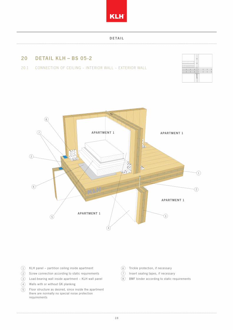
20 DETAIL KLH – BS 05 -2
20.1 connection of ceiling – interior wall – exterior wall
5
8
6
4
3
1
7
Insert sealing tapes, if necessary
Trickle protection, if necessary
8
7
BMF binder according to static requirements
6
Floor structure as desired, since inside the apartment there are normally no special noise protection requirements
Walls with or without GK planking
Load-bearing wall inside apartment – KLH wall panel
Screw connection according to static requirements
KLH panel – partition ceiling inside apartment
5
4
3
1
2
2
2
2 8
D E T A I L

21 DETAIL KLH – BS 05 -3
21.1 connection of ceiling – exterior wall
APARTMENT 15
8
9
10
11
7
6
43
1
2
12
16
13
14
Back-ventilated façade
Wind proofing
2- layer insulation level, wooden structure in between
Screw connection of wooden elements according to static requirements
Horizontal wood only at wall base and wall f lanning, ver tical wood free-standing between these two wooden elements
Convection barrier11
12
16
13
14
15
15
6
8
APARTMENT 1
Convection barrier during transport
KLH wall
Screw connection according to static requirements
Connect sealing level
Complete insulation tapes on site
Prefabricated wall on upper f loor
Fold in convection barrier
Apply sealing tape with glue
KLH ceiling
Prefabricated wall on ground floor
5
8
9
10
7
6
4
1
2
3 R’w = 51(-2;-7) dB
Ex terior wall: Aw 03
wall s tructureFaçade – wood(board, planks – sealed)Back-ventilation level(Bat tens screwed tight with KLH)2 x 80 mm rock wool across entire surface(Heralan FP)KLH 3s 94 mm15 mm GKF
2 9
D E T A I L

N O T E S

N O T E S

N O T E S


For love of nature
Pr inted on ecolog ical ly f r iendly paper
K L H M A S S I V H O L Z G M B H
Gewerbes t raße 4 | 8842 Teufenbach -Katsch | Aus t r ia
Tel +43 (0)3588 8835 0 | Fax +43 (0)3588 8835 20
of f [email protected] | www.k lh.at


![New Old Thoughts On Some History Measuring Home Speakers · Winslow Burhoe (EPI), C. Victor Campos (AR, KLH), Henry Kloss (KLH), Andrew Petite [Kotsatos] (KLH, Advent, Boston Acoustics),](https://static.documents.pub/doc/80x56/5e7c8de8a99a64700d749be3/new-old-thoughts-on-some-history-measuring-home-winslow-burhoe-epi-c-victor.jpg)


