Page 1
Symmetrical Components
Symmetrical Component AnalysisSynthesis of Unsymmetrical Phasors from
Their Symmetrical ComponentsThe Symmetrical Components of Unsym
metrical PhasorsPhase Shift of Symmetrical Components i
n or Transformer BanksPower in Terms of Symmetrical Compone
nts Y Y
Page 2
Symmetrical ComponentsUnsymmetrical Series ImpedanceSequence Impedance and Sequence
NetworkSequence Networks of Unloaded gen
eratorsSequence NetworkZero-Sequence Network
Page 3
Symmetrical Component Analysis
Goal :
Symmetrical component analysis is a very useful tool
for dealing with unbalanced three-phase faults.
Page 4
Synthesis of Unsymmetrical Phases from Their Symmetrical Components 1
“An unbalanced system of n related phasors can be resolved into
n systems of balanced phasors called the symmetrical components
of the original phasors. The n phasors of each set of components
are equal in lengths , and the angles between adjacent phasors of
the set are equal.”
by C.L Fortescue , 1918
Page 5
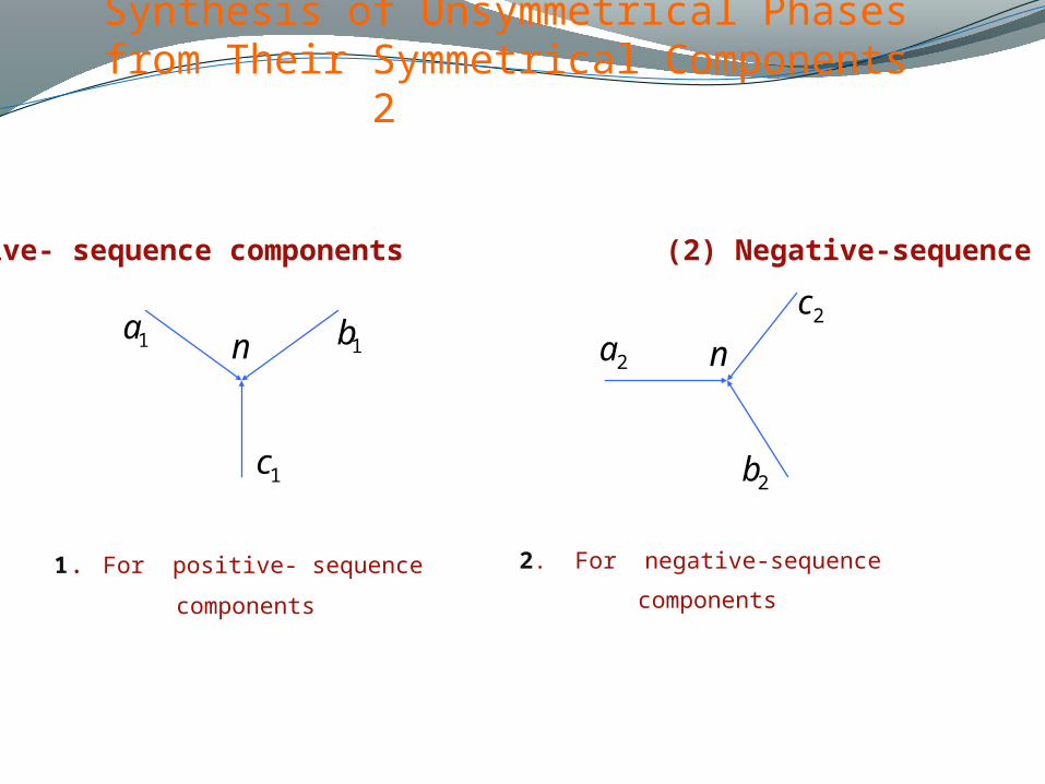
Synthesis of Unsymmetrical Phases from Their Symmetrical Components 2
1. For positive- sequence
components
2. For negative-sequence
components
(1) Positive- sequence components (2) Negative-sequence components
1a 1b
1c
2a2c
2b
n n
Page 6
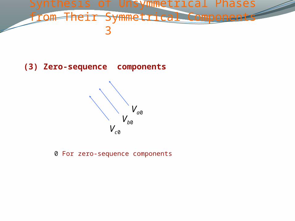
Synthesis of Unsymmetrical Phases from Their Symmetrical Components 3
(3) Zero-sequence components
0aV0bV
0cV
0 For zero-sequence components
Page 7
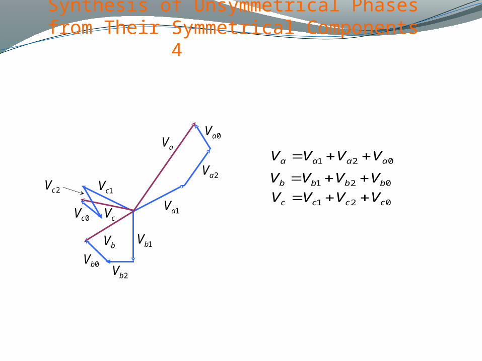
Synthesis of Unsymmetrical Phases from Their Symmetrical Components 4
021 aaaa VVVV
021 bbbb VVVV
021 cccc VVVV
0aV
2aV
aV
1aV
1bV
2bV0bV
1cV
bV
0cV cV
2cV
Page 8
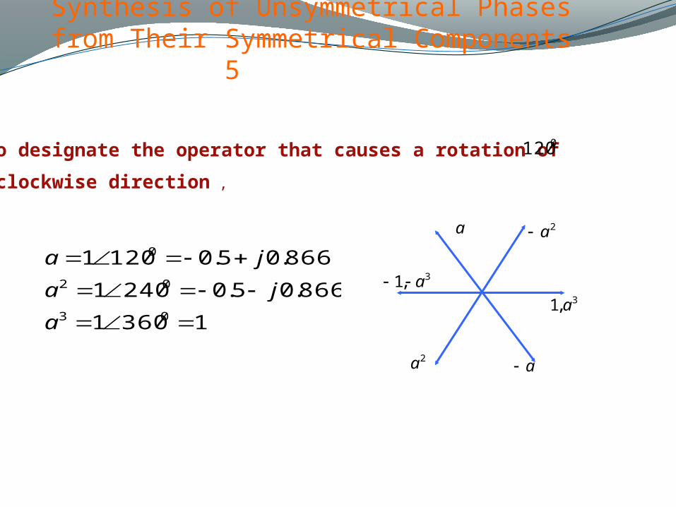
Synthesis of Unsymmetrical Phases from Their Symmetrical Components 5
Use a to designate the operator that causes a rotation of in the
counterclockwise direction ,
13601
866.05.02401
866.05.01201
03
02
0
a
ja
ja
0120
2a
3,1 a
2a a
3,1 a
a
Page 9
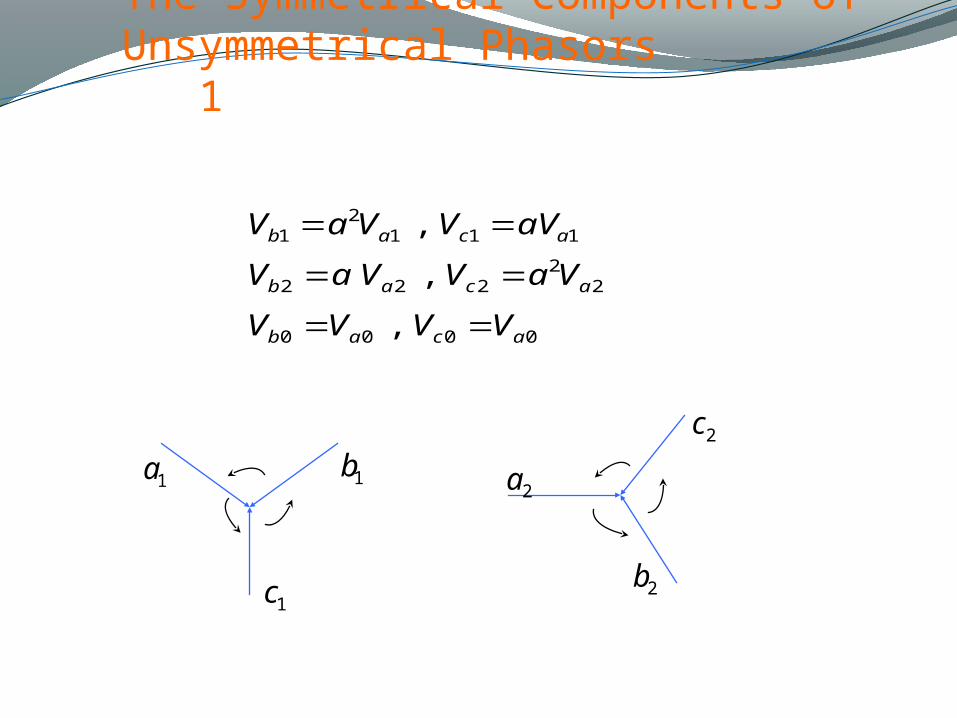
The Symmetrical Components of Unsymmetrical Phasors 1
0000
22
222
1112
1
,
,
,
acab
acab
acab
VVVV
VaVVaV
aVVVaV
1a 1b
1c
2a
2c
2b
Page 10
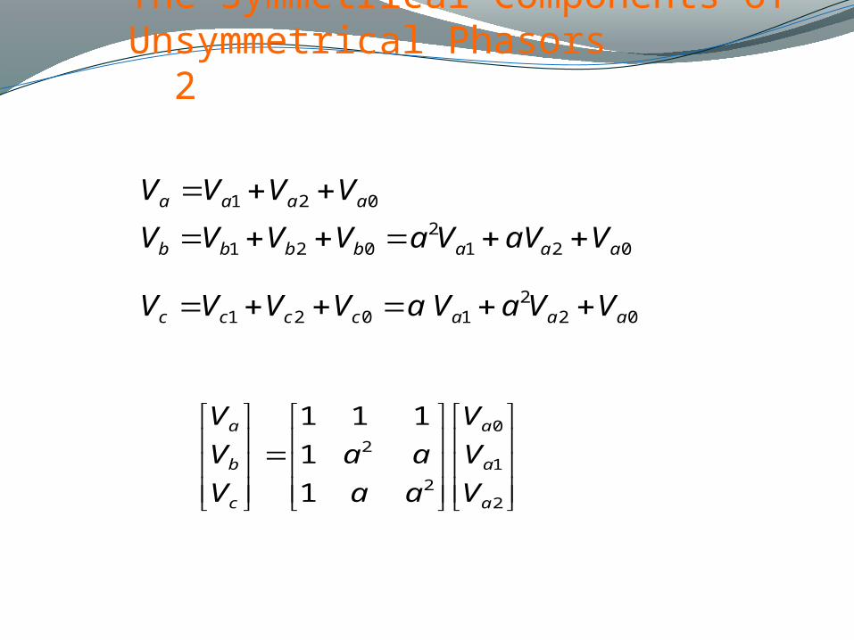
The Symmetrical Components of Unsymmetrical Phasors 2
022
1021
0212
021
021
aaacccc
aaabbbb
aaaa
VVaVaVVVV
VaVVaVVVV
VVVV
2
1
0
2
2
1
1
111
a
a
a
c
b
a
V
V
V
aa
aa
V
V
V
Page 11
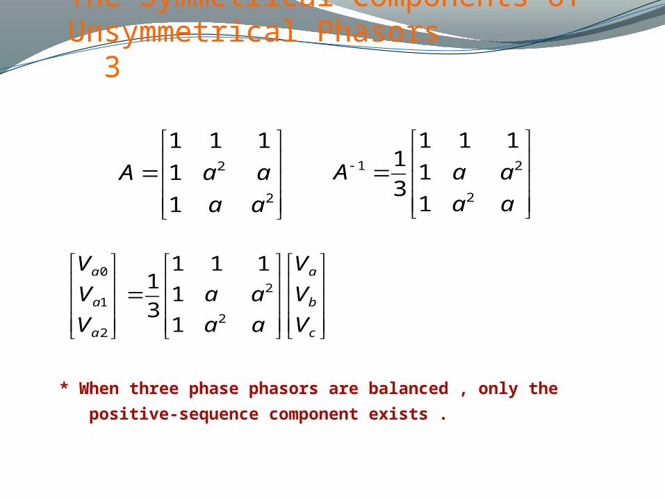
The Symmetrical Components of Unsymmetrical Phasors 3
2
2
1
1
111
aa
aaA
aa
aaA2
21
1
1
111
3
1
c
b
a
a
a
a
V
V
V
aa
aa
V
V
V
2
2
2
1
0
1
1
111
3
1
* When three phase phasors are balanced , only the
positive-sequence component exists .
Page 12
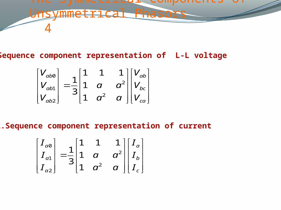
The Symmetrical Components of Unsymmetrical Phasors 4
1.Sequence component representation of L-L voltage
ca
bc
ab
ab
ab
ab
V
V
V
aa
aa
V
V
V
2
2
2
1
0
1
1
111
3
1
2.Sequence component representation of current
c
b
a
a
a
a
I
I
I
aa
aa
I
I
I
2
2
2
1
0
1
1
111
3
1
Page 13
The Symmetrical Components of Unsymmetrical Phasors 5
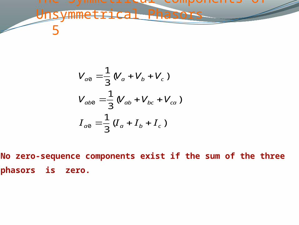
)(3
1
)(3
1
)(3
1
0
0
0
cbaa
cabcabab
cbaa
IIII
VVVV
VVVV
No zero-sequence components exist if the sum of the three
phasors is zero.
Page 14
The Symmetrical Components of Unsymmetrical Phasors 6
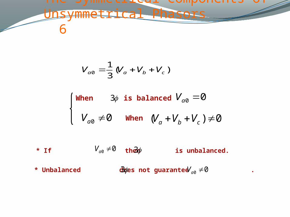
)(3
10 cbaa VVVV
00 aV
00 aV3When is balanced
When 0)( cba VVV
* If then is unbalanced.
* Unbalanced does not guarantee .
00 aV 3
3 00 aV
Page 15
The Symmetrical Components of Unsymmetrical Phasors 7
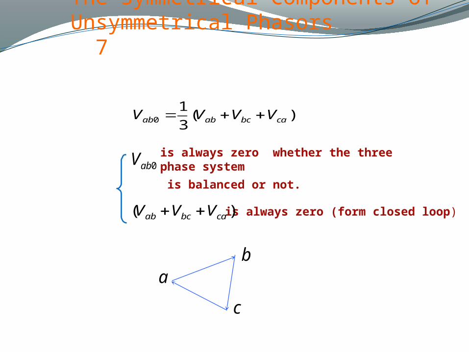
)(3
10 cabcabab VVVV
is always zero whether the three phase system
is balanced or not.
)( cabcab VVV is always zero (form closed loop)
0abV
ab
c
Page 16
The Symmetrical Components of Unsymmetrical Phasors 8
aI
bI
cI
aI
bI
cI
aI
bI
cInI
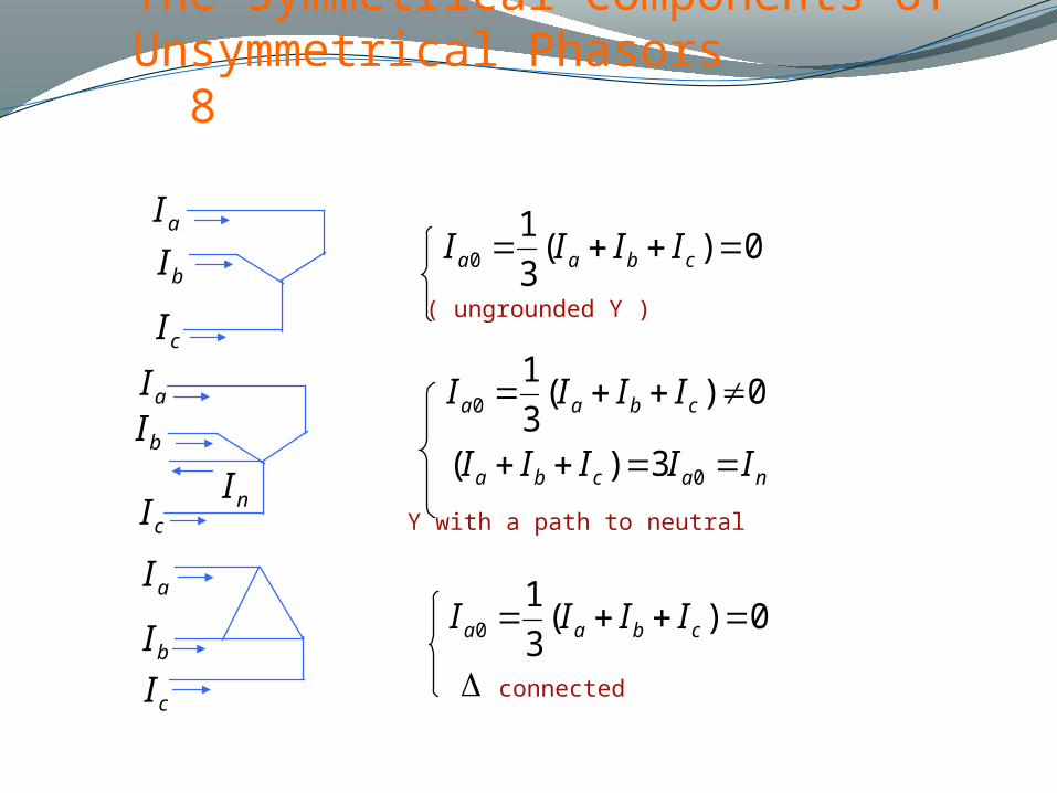
0)(3
10 cbaa IIII
( ungrounded Y )
0)(3
10 cbaa IIII
nacba IIIII 03)(
Y with a path to neutral
0)(3
10 cbaa IIII
connected
Page 17
The Symmetrical Components of Unsymmetrical Phasors 9
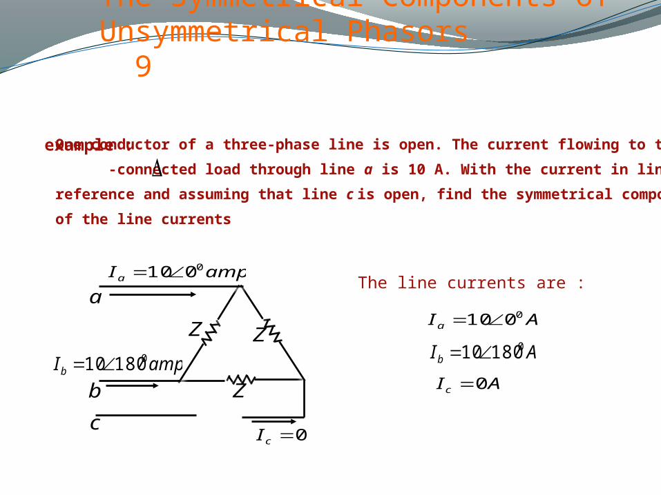
example : One conductor of a three-phase line is open. The current flowing to the
-connected load through line a is 10 A. With the current in line a as
reference and assuming that line c is open, find the symmetrical components
of the line currents
Z Z
Z
a
c
b
ampIa0010
ampIb018010
0cI
AIa0010
AIb018010
AIc 0
The line currents are :
Page 18
The Symmetrical Components of Unsymmetrical Phasors 10
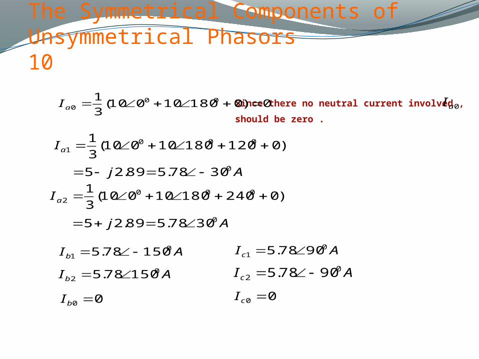
0)018010010(3
1 000 aI
)012018010010(3
1 0001 aI
Aj 03078.589.25
)024018010010(3
1 0002 aI
Aj 03078.589.25
AIb0
1 15078.5
AIb0
2 15078.5
00 bI
AIc0
1 9078.5
AIc0
2 9078.5
00 cI
Since there no neutral current involved ,
should be zero .0aI
Page 19
Phase Shift of Symmetrical Components in or Transformers Banks 1Y Y
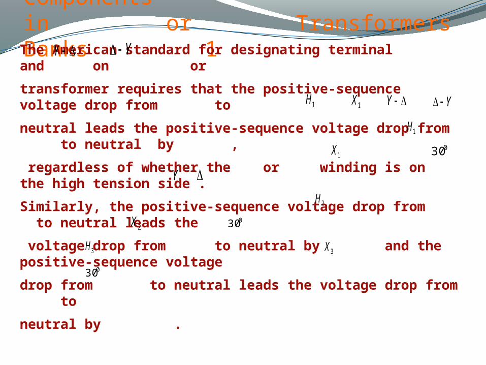
The American standard for designating terminal and on or
transformer requires that the positive-sequence voltage drop from to
neutral leads the positive-sequence voltage drop from to neutral by ,
regardless of whether the or winding is on the high tension side .
Similarly, the positive-sequence voltage drop from to neutral leads the
voltage drop from to neutral by and the positive-sequence voltage
drop from to neutral leads the voltage drop from to
neutral by .
1H
1X Y1H
1X030
030
3H
2X
3X
2H
030
Y
Y
Page 20
Phase Shift of Symmetrical Components in or Transformers Banks 2Y Y
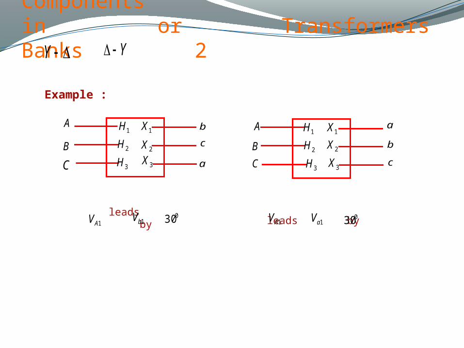
Example :
A
B
C a
c
b1H
3H2H
2X1X
3X
A
B
C
a
b
c
1H
3H2H
1X
2X
3X
1AV 1bV 030leads by 1aVleads by1AV 030
Page 21
Phase Shift of Symmetrical Components in or Transformers Banks 3Y Y
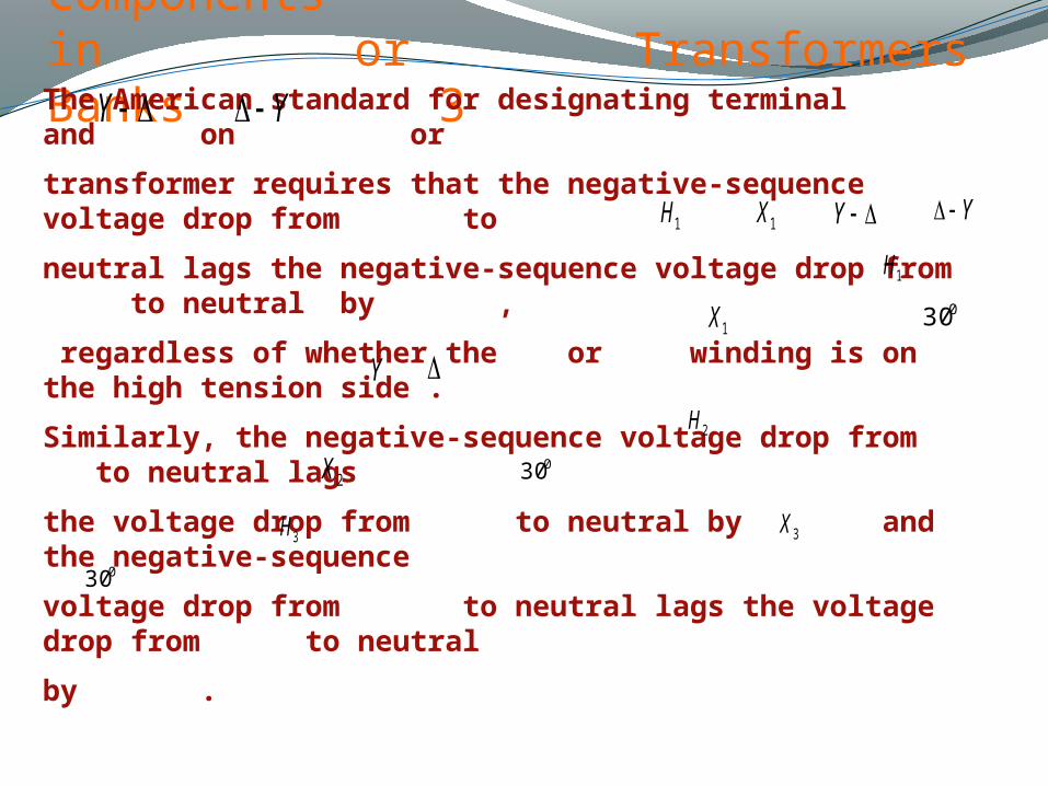
The American standard for designating terminal and on or
transformer requires that the negative-sequence voltage drop from to
neutral lags the negative-sequence voltage drop from to neutral by ,
regardless of whether the or winding is on the high tension side .
Similarly, the negative-sequence voltage drop from to neutral lags
the voltage drop from to neutral by and the negative-sequence
voltage drop from to neutral lags the voltage drop from to neutral
by .
1H
1X Y1H
1X030
030
3H
2X
3X
2H
030
Y
Y
Page 22
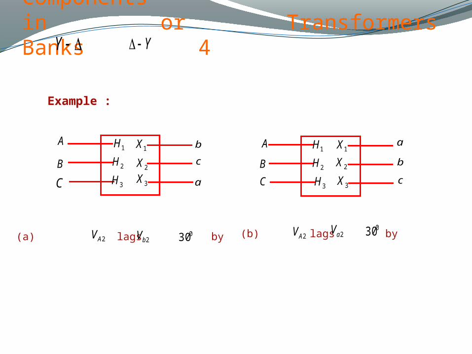
Phase Shift of Symmetrical Components in or Transformers Banks 4Y Y
A
B
C a
c
b1H
3H2H
2X1X
3X
A
B
C
a
b
c
1H
3H2H
1X
2X
3X
2aV(b) lags by2AV030
2bV(a) lags by2AV 030
Example :
Page 23
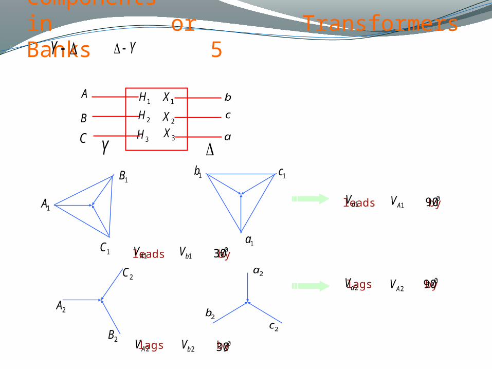
Phase Shift of Symmetrical Components in or Transformers Banks 5Y Y
A
B
C a
c
b1H
3H2H
2X1X
3X
2B
2A
2C
2b
2c
2a
1B
1A
1C
1b
1a
1c
1AVleads by1aV 090
2AVlags by2aV090
1bVleads by1AV 030
2bVlags by2AV 030
Y
Page 24
Phase Shift of Symmetrical Components in or Transformers Banks 6
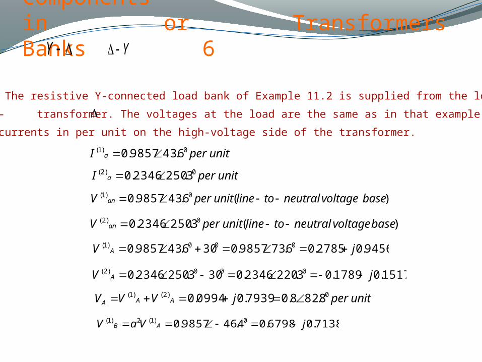
Example 11.7. The resistive Y-connected load bank of Example 11.2 is supplied from the low-voltage
Y-side of a Y- transformer. The voltages at the load are the same as in that example. Find the line
voltages and currents in per unit on the high-voltage side of the transformer.
unitperI a0)1( 6.439857.0
unitperI a0)2( 3.2502346.0
)(6.439857.0 0)1( basevoltageneutraltolineunitperV an
)(3.2502346.0 0)2( basevoltageneutraltolineunitperV an
9456.02785.06.739857.0306.439857.0 000)1( jV A
1517.01789.03.2202346.0303.2502346.0 000)2( jV A
unitperjVVV AAA0)2()1( 8.828.07939.00994.0
7138.06798.04.469857.0 0)1(2)1( jVaV AB
Y Y
Page 25
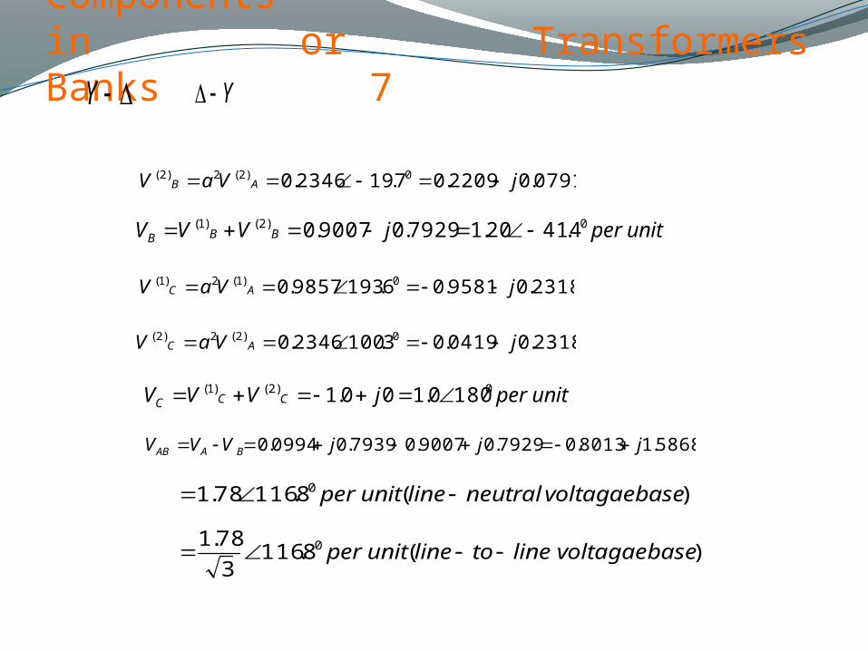
Phase Shift of Symmetrical Components in or Transformers Banks 7
0791.02209.07.192346.0 0)2(2)2( jVaV AB
unitperjVVV BBB0)2()1( 4.4120.17929.09007.0
2318.09581.06.1939857.0 0)1(2)1( jVaV AC
2318.00419.03.1002346.0 0)2(2)2( jVaV AC
unitperjVVV CCC0)2()1( 1800.100.1
5868.18013.07929.09007.07939.00994.0 jjjVVV BAAB
)(8.11678.1 0 basevoltagaeneutrallineunitper
)(8.1163
78.1 0 basevoltagaelinetolineunitper
Y Y
Page 26
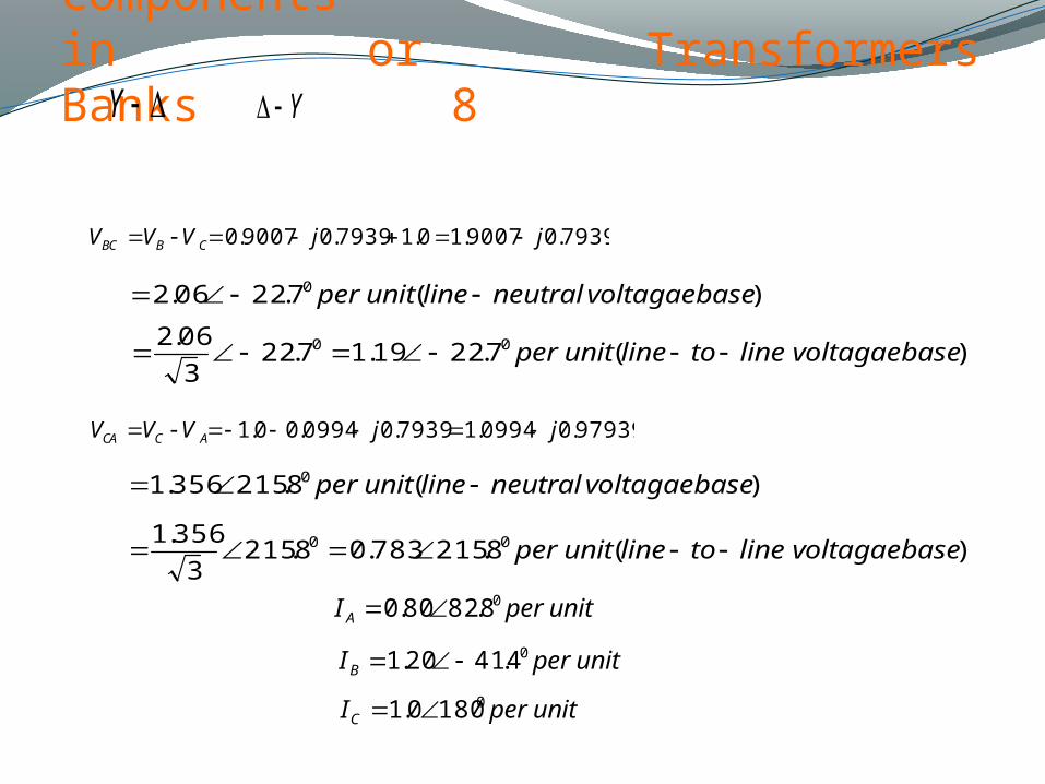
Phase Shift of Symmetrical Components in or Transformers Banks 8
7939.09007.10.17939.09007.0 jjVVV CBBC
)(7.2206.2 0 basevoltagaeneutrallineunitper
)(7.2219.17.223
06.2 00 basevoltagaelinetolineunitper
97939.00994.17939.00994.00.1 jjVVV ACCA
)(8.215356.1 0 basevoltagaeneutrallineunitper
)(8.215783.08.2153
356.1 00 basevoltagaelinetolineunitper
unitperI A08.8280.0
unitperIB04.4120.1
unitperIC01800.1
Y Y
Page 27
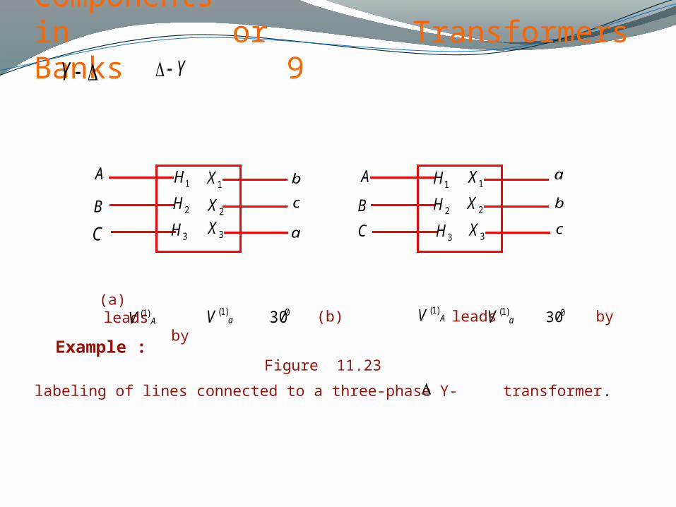
Phase Shift of Symmetrical Components in or Transformers Banks 9
(b) leads by 030aV )1((a) leads byAV )1( 030 AV )1(aV )1(
Figure 11.23
labeling of lines connected to a three-phase Y- transformer.
Y Y
A
B
C a
c
b1H
3H2H
2X1X
3X
A
B
C
a
b
c
1H
3H2H
1X
2X
3X
Example :
Page 28
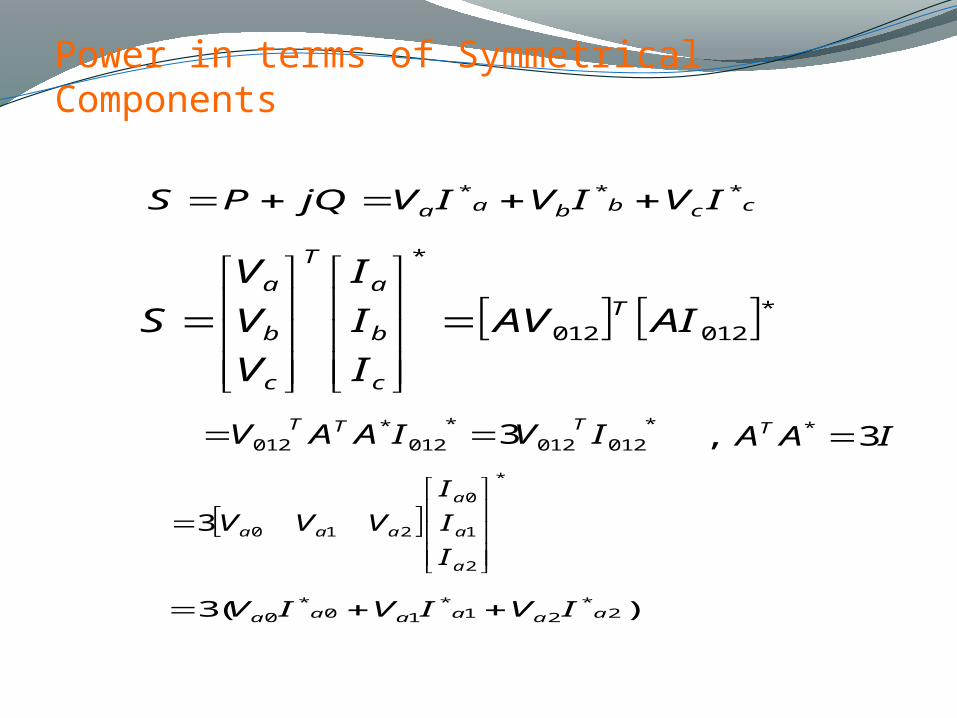
Power in terms of Symmetrical Components
ccbbaa IVIVIVjQPS ***
*012012
*
AIAV
I
I
I
V
V
V
S T
c
b
a
T
c
b
a
*012012
*012
*012 3 IVIAAV TTT
*
2
1
0
2103
a
a
a
aaa
I
I
I
VVV
)(3 2*
21*
10*
0 aaaaaa IVIVIV
IAAT 3, *
Page 29
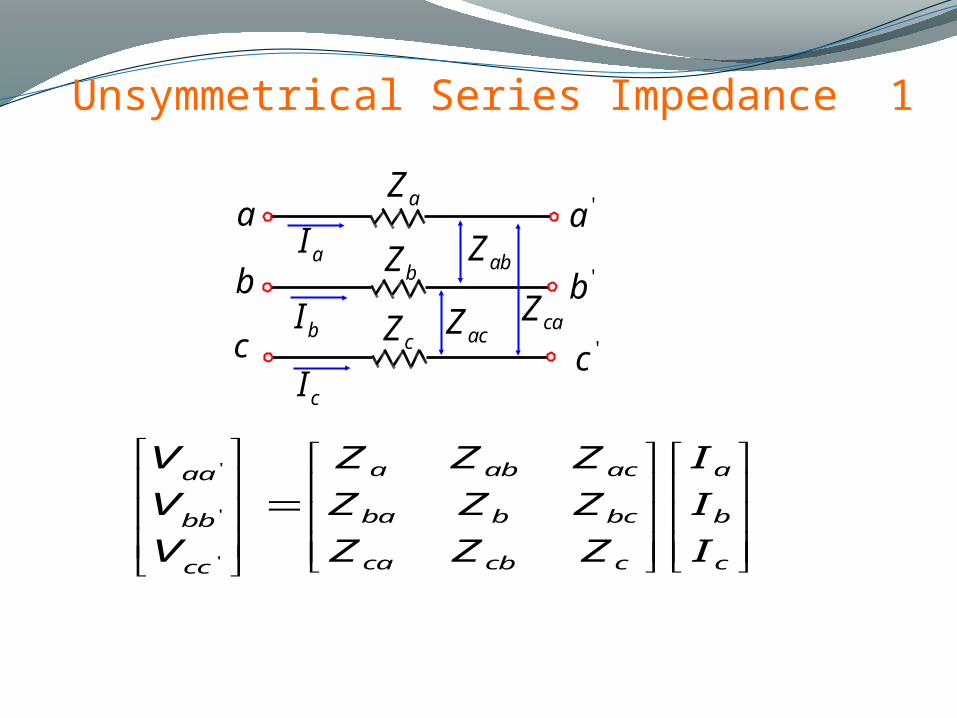
Unsymmetrical Series Impedance 1
a
b
c 'c
'b
'a
cZ
bZ
aZ
aI
bI
cI
caZacZ
abZ
c
b
a
ccbca
bcbba
acaba
cc
bb
aa
I
I
I
ZZZ
ZZZ
ZZZ
V
V
V
'
'
'
Page 30
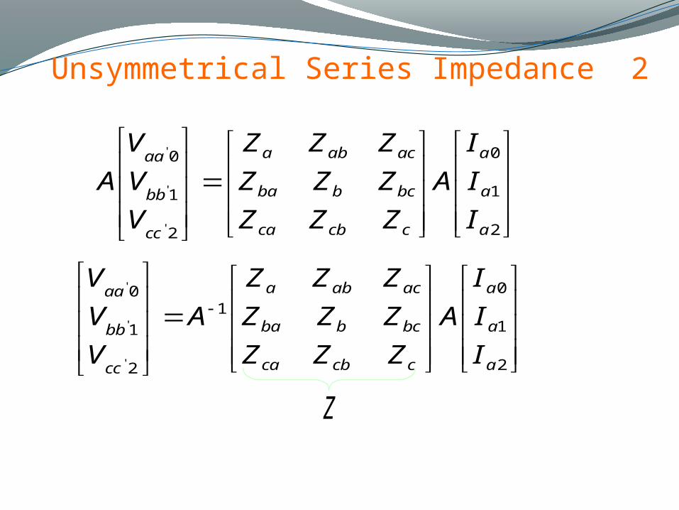
Unsymmetrical Series Impedance 2
2
1
0
2
1
0
'
'
'
a
a
a
ccbca
bcbba
acaba
cc
bb
aa
I
I
I
A
ZZZ
ZZZ
ZZZ
V
V
V
A
2
1
01
2
1
0
'
'
'
a
a
a
ccbca
bcbba
acaba
cc
bb
aa
I
I
I
A
ZZZ
ZZZ
ZZZ
A
V
V
V
Z
Page 31
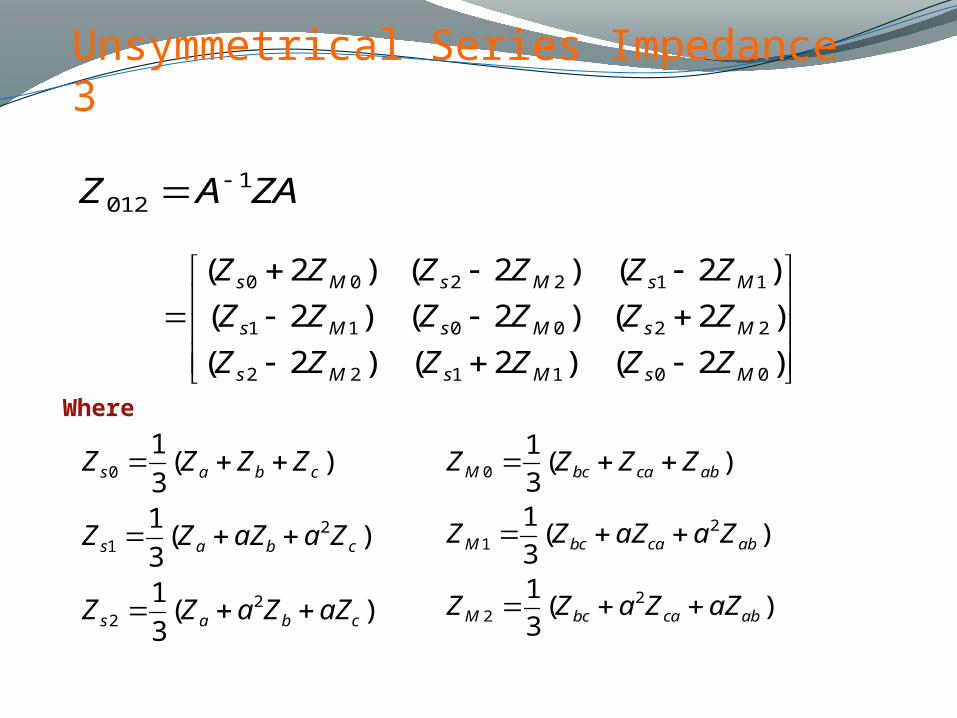
Unsymmetrical Series Impedance 3
ZAAZ 1012
)2()2()2(
)2()2()2(
)2()2()2(
001122
220011
112200
MsMsMs
MsMsMs
MsMsMs
ZZZZZZ
ZZZZZZ
ZZZZZZ
Where
)(3
1
)(3
1
)(3
1
22
21
0
cbas
cbas
cbas
aZZaZZ
ZaaZZZ
ZZZZ
)(3
1
)(3
1
)(3
1
22
21
0
abcabcM
abcabcM
abcabcM
aZZaZZ
ZaaZZZ
ZZZZ
Page 32
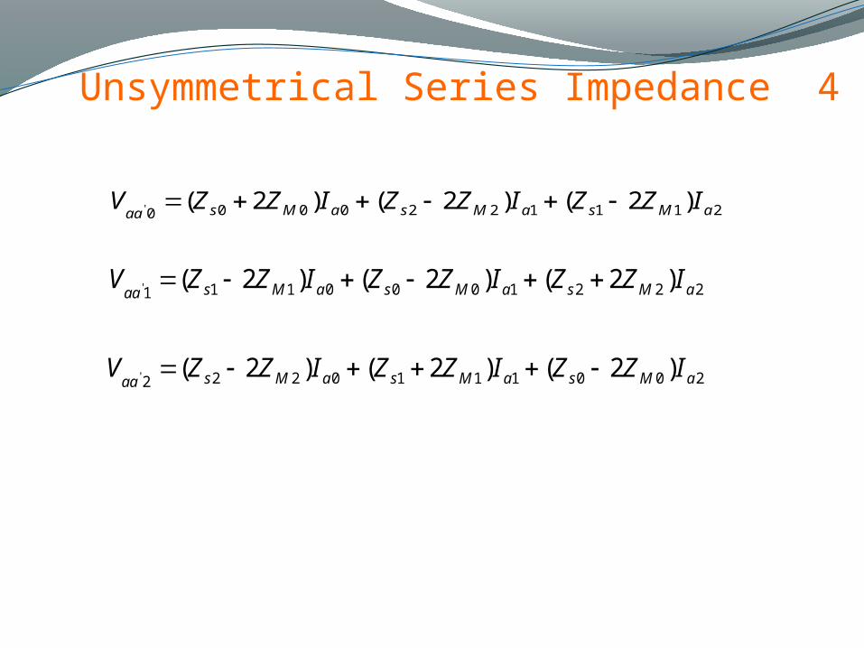
Unsymmetrical Series Impedance 4
2111220000)2()2()2(' aMsaMsaMsaaIZZIZZIZZV
2221000111)2()2()2(' aMsaMsaMsaaIZZIZZIZZV
2001110222)2()2()2(' aMsaMsaMsaaIZZIZZIZZV
Page 33
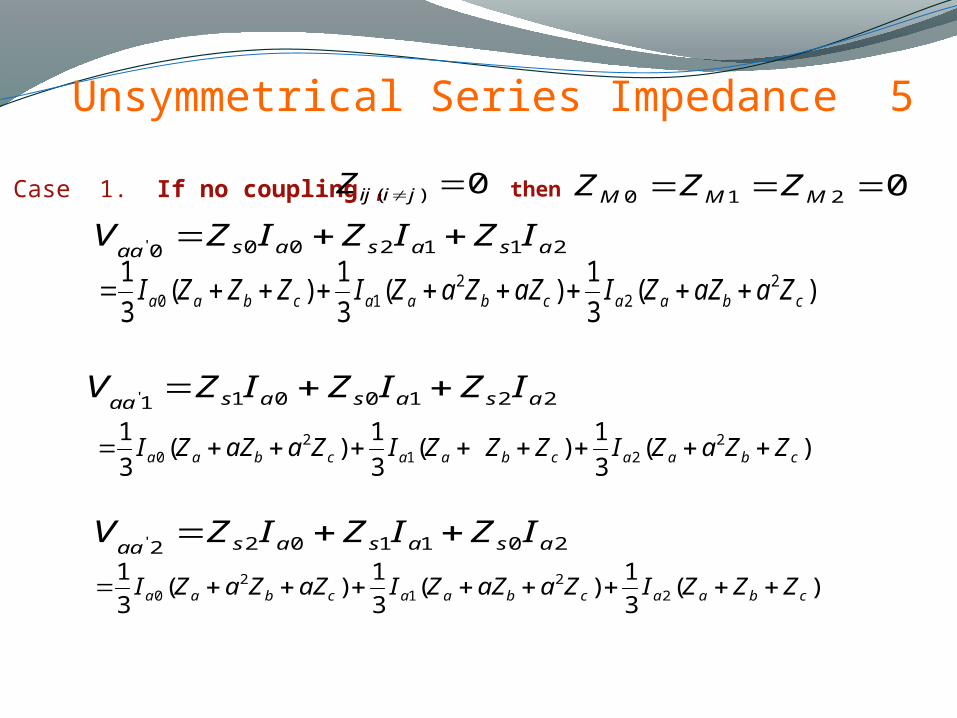
Unsymmetrical Series Impedance 5
Case 1. If no coupling , 0)( jiijZ
2112000' asasasaaIZIZIZV
)(3
1)(
3
1)(
3
1 22
210 cbaacbaacbaa ZaaZZIaZZaZIZZZI
2011022' asasasaaIZIZIZV
2210011' asasasaaIZIZIZV
)(3
1)(
3
1)(
3
1 221
20 cbaacbaacbaa ZZaZIZZZIZaaZZI
)(3
1)(
3
1)(
3
12
21
20 cbaacbaacbaa ZZZIZaaZZIaZZaZI
then 0210 MMM ZZZ
Page 34
Unsymmetrical Series Impedance 6
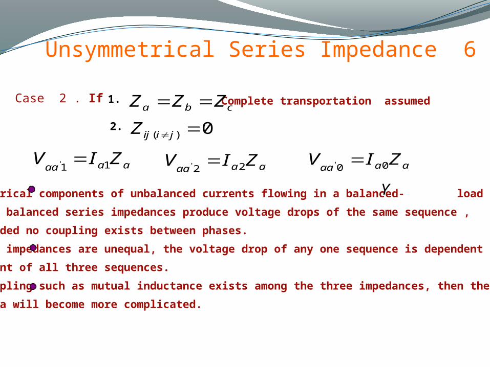
Case 2 . If
0)( jiijZcba ZZZ
aaaaZIV 11'
aaaa
ZIV 22' aaaaZIV 00'
Symmetrical components of unbalanced currents flowing in a balanced- load
or in balanced series impedances produce voltage drops of the same sequence ,
provided no coupling exists between phases.
If the impedances are unequal, the voltage drop of any one sequence is dependent on the
current of all three sequences.
If coupling such as mutual inductance exists among the three impedances, then the
formula will become more complicated.
Y
1.
2.
Complete transportation assumed
Page 35
Unsymmetrical Series Impedance 7
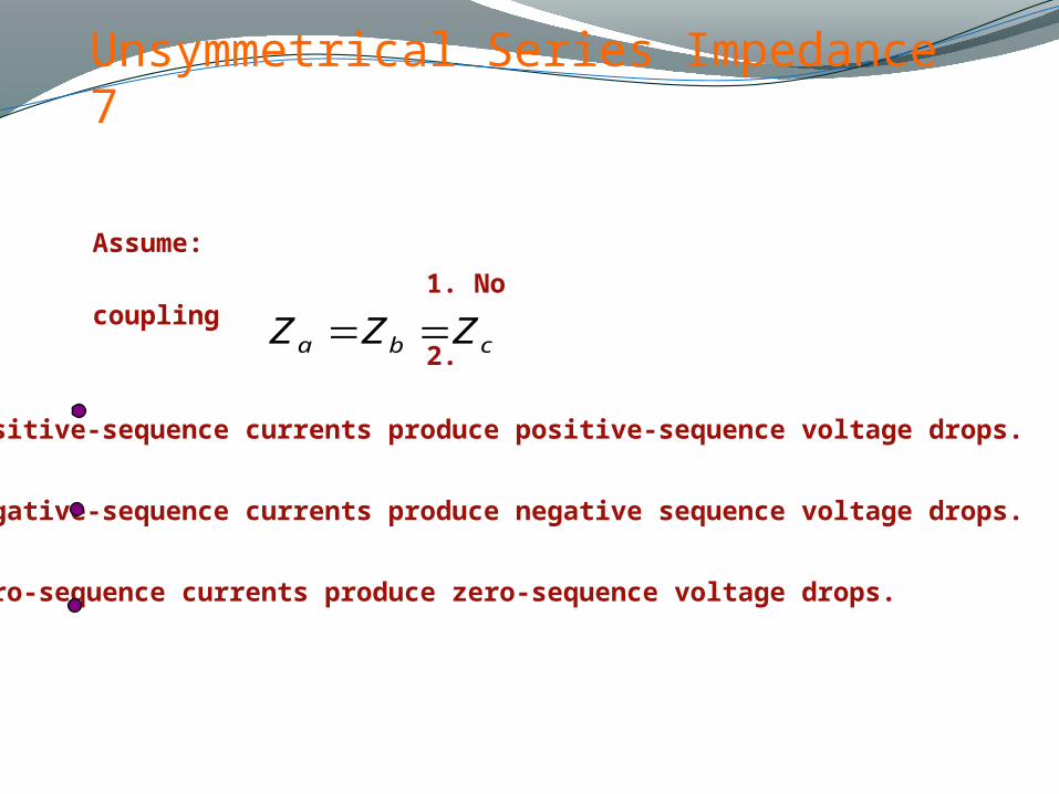
Assume:
1. No coupling
2.
Positive-sequence currents produce positive-sequence voltage drops.
Negative-sequence currents produce negative sequence voltage drops.
zero-sequence currents produce zero-sequence voltage drops.
cba ZZZ
Page 36
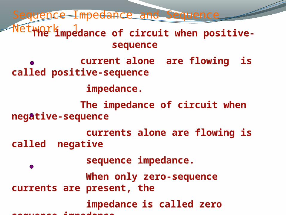
Sequence Impedance and Sequence Network 1
The impedance of circuit when positive- sequence
current alone are flowing is called positive-sequence
impedance.
The impedance of circuit when negative-sequence
currents alone are flowing is called negative
sequence impedance.
When only zero-sequence currents are present, the
impedance is called zero sequence impedance.
Page 37
Sequence Impedance and Sequence Network 2
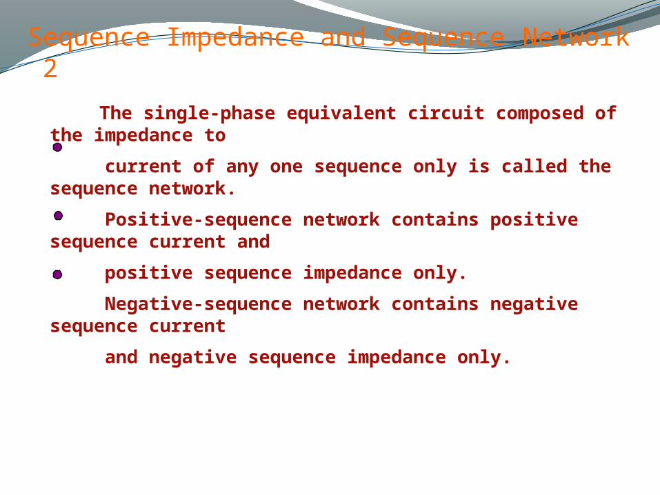
The single-phase equivalent circuit composed of the impedance to
current of any one sequence only is called the sequence network.
Positive-sequence network contains positive sequence current and
positive sequence impedance only.
Negative-sequence network contains negative sequence current
and negative sequence impedance only.
Page 38
Sequence Impedance and Sequence Network 3
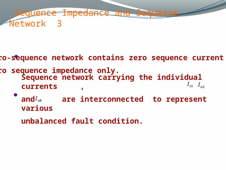
Sequence network carrying the individual currents ,
and are interconnected to represent various
unbalanced fault condition.
1aI 2aI
0aI
Zero-sequence network contains zero sequence current and
zero sequence impedance only.
Page 39
Sequence Impedance and Sequence Network 4
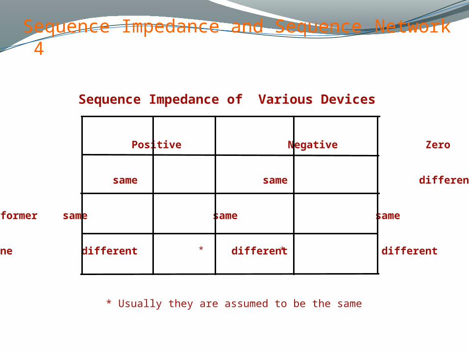
Sequence Impedance of Various Devices
Positive Negative Zero
Line same same different
Transformer same same same
Machine different different different**
* Usually they are assumed to be the same
Page 40
Sequence Networks of Unloaded Generators 1
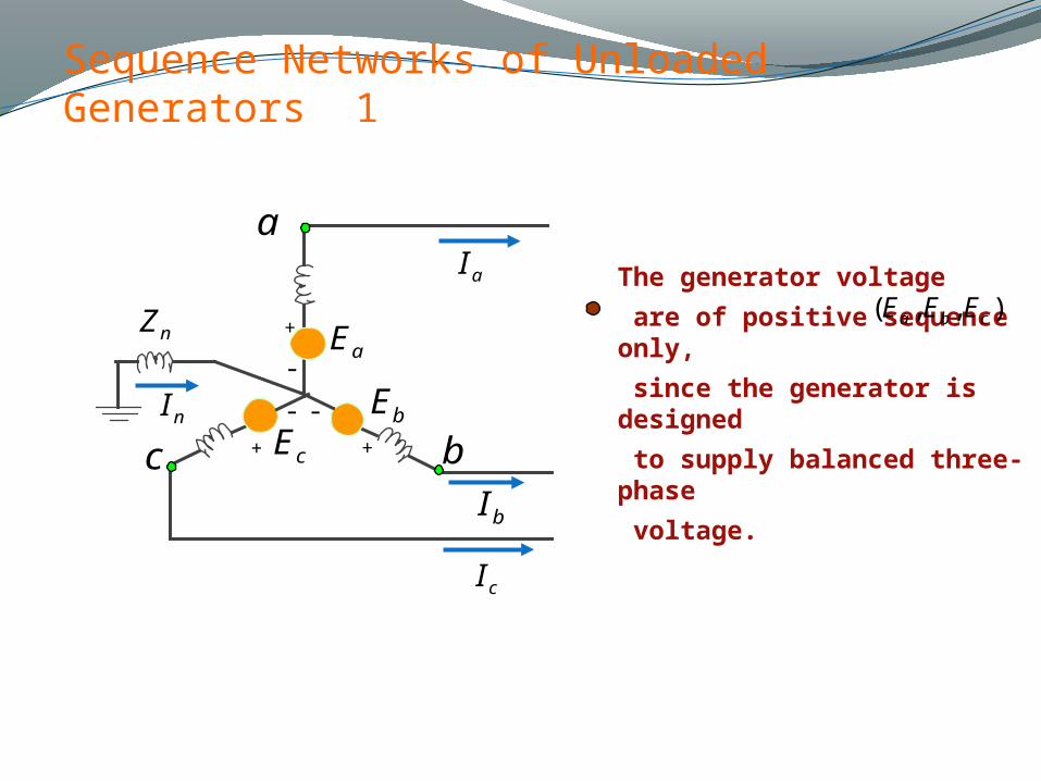
The generator voltage
are of positive sequence only,
since the generator is designed
to supply balanced three-phase
voltage.
aI
bI
cI
nI
cEbE
aE
bc
a
++
+
-
--
nZ),,( cba EEE
Page 41
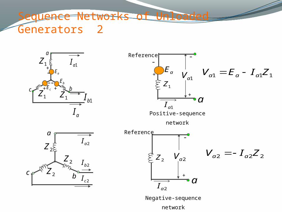
Sequence Networks of Unloaded Generators 2
2aI
2cI
2bI
a
c b
2Z
2Z2Z 2aV
2aIa
2Z
+
-
Negative-sequence
network
+
-
1aVaE
1aIa
1Z
+
-
Positive-sequence
network
Reference
Reference
1aI
1bIcE
bE
aE
bc
a
+
++
-
--
1Z
1Z1Z
aI
111 ZIEV aaa
222 ZIV aa
Page 42
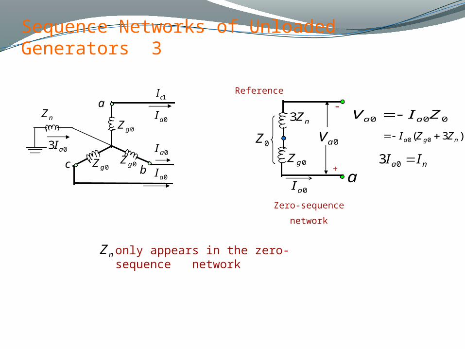
Sequence Networks of Unloaded Generators 3
1cI
0aI
0aI
0aI
a
c b
0gZ
0gZ 0gZ
0aI
0aV
a0gZ
+
-nZ3
0Z
Zero-sequence
network
Reference
only appears in the zero-sequence network
nZ
000 ZIV aa nZ
03 aI)3( 00 nga ZZI
na II 03
Page 43
Sequence Networks of Unloaded Generators 4
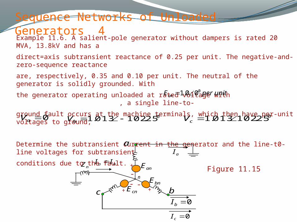
Example 11.6. A salient-pole generator without dampers is rated 20 MVA, 13.8kV and has a
direct=axis subtransient reactance of 0.25 per unit. The negative-and-zero-sequence reactance
are, respectively, 0.35 and 0.10 per unit. The neutral of the generator is solidly grounded. With
the generator operating unloaded at rated voltage with , a single line-to-
ground fault occurs at the machine terminals, which then have per-unit voltages to ground,
Determine the subtransient current in the generator and the line-t0-line voltages for subtransient
conditions due to the fault.
unitperEan000.1
0aV025.102013.1 cV
025.102013.1 bV
0cI
aI
0bI
na II
cnEbnE
anE
bc
a
++
+
-- -
nZ
n
Figure 11.15
Page 44
Sequence Networks of Unloaded Generators 5
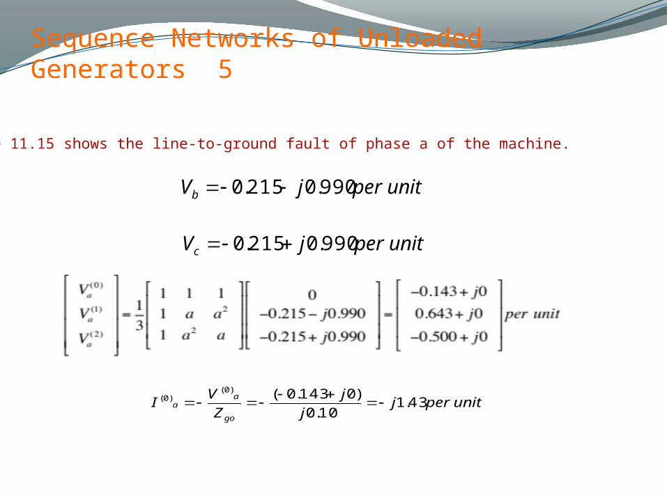
Figure 11.15 shows the line-to-ground fault of phase a of the machine.
unitperjVb 990.0215.0
unitperjVc 990.0215.0
unitperjj
j
Z
VI
go
aa 43.1
10.0
)0143.0()0()0(
Page 45
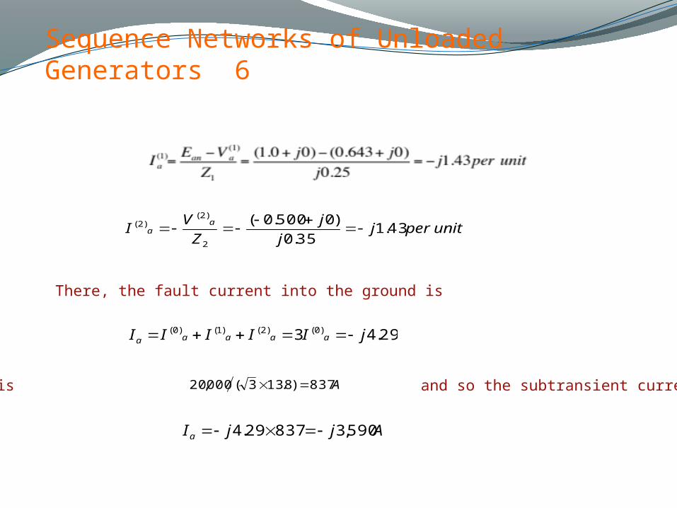
Sequence Networks of Unloaded Generators 6
unitperjj
j
Z
VI
aa 43.1
35.0
)0500.0(
2
)2()2(
29.43 )0()2()1()0( jIIIII aaaaa
There, the fault current into the ground is
The base current is and so the subtransient current in line a isA837)8.133(000,20
AjjIa 590,383729.4
Page 46
Sequence Networks of Unloaded Generators 7
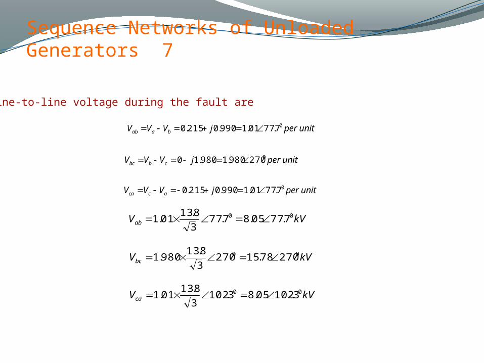
Line-to-line voltage during the fault are
unitperjVVV baab07.7701.1990.0215.0
unitperjVVV cbbc0270980.1980.10
unitperjVVV acca07.7701.1990.0215.0
kVVab00 7.7705.87.77
3
8.1301.1
kVVbc00 27078.15270
3
8.13980.1
kVVca00 3.10205.83.102
3
8.1301.1
Page 47
Sequence Networks of Unloaded Generators 8
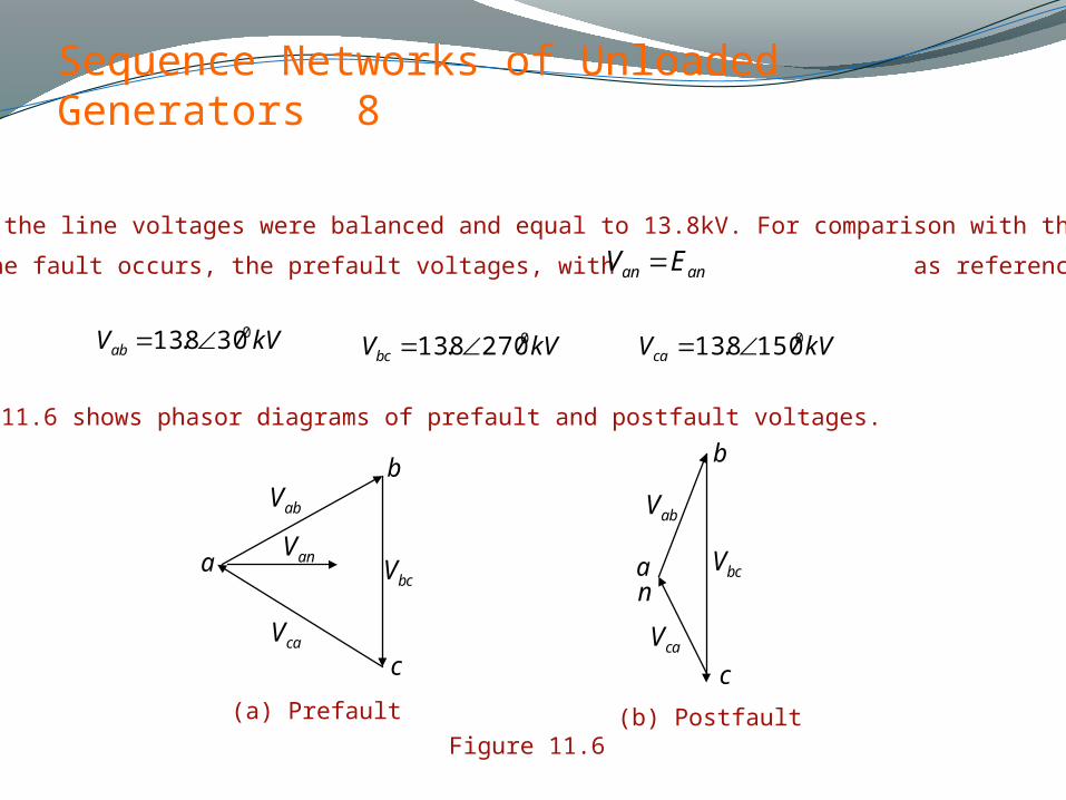
Before the fault the line voltages were balanced and equal to 13.8kV. For comparison with the line
voltages after the fault occurs, the prefault voltages, with as reference, are given asanan EV
kVVab0308.13 kVVbc
02708.13 kVVca01508.13
Figure 11.6 shows phasor diagrams of prefault and postfault voltages.
Figure 11.6
(a) Prefault (b) Postfault
anV
caVcaV
bcVbcV
abVabV
aan
b b
c c
Page 48
Sequence Networks of Unloaded Generators 9
The positive-sequence diagram of a generator is composed of an emf in series with the positive-sequence
impedance of the generator.
The negative and zero-sequence diagrams contain no
emfs but include the negative and zero-sequence
impedances of the generator respectively.
Page 49
Sequence Networks 1
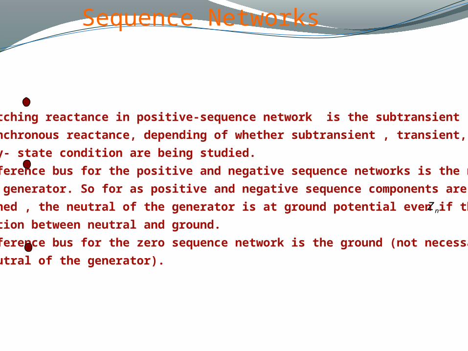
The matching reactance in positive-sequence network is the subtransient ,transient,
or synchronous reactance, depending of whether subtransient , transient, or
steady- state condition are being studied.
The reference bus for the positive and negative sequence networks is the neutral
of the generator. So for as positive and negative sequence components are
concerned , the neutral of the generator is at ground potential even if these is
connection between neutral and ground.
The reference bus for the zero sequence network is the ground (not necessary
the neutral of the generator).
nZ
Page 50
Sequence Networks 2
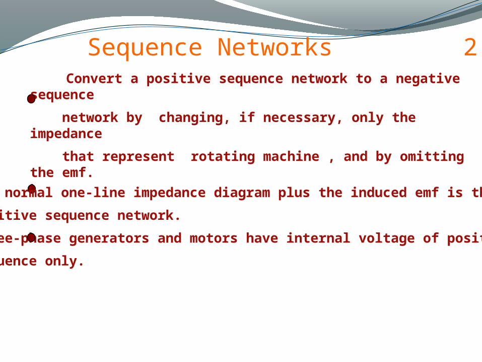
Convert a positive sequence network to a negative sequence
network by changing, if necessary, only the impedance
that represent rotating machine , and by omitting the emf.
The normal one-line impedance diagram plus the induced emf is the
positive sequence network.
Three-phase generators and motors have internal voltage of positive
sequence only.
Page 51
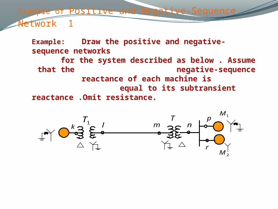
Example of Positive and Negative-Sequence Network 1
Example: Draw the positive and negative-sequence networks for the system described as below . Assume that the
negative-sequence reactance of each machine is equal to its subtransient reactance .Omit resistance.
1T1M
T
r
pm nk l
2M
Page 52
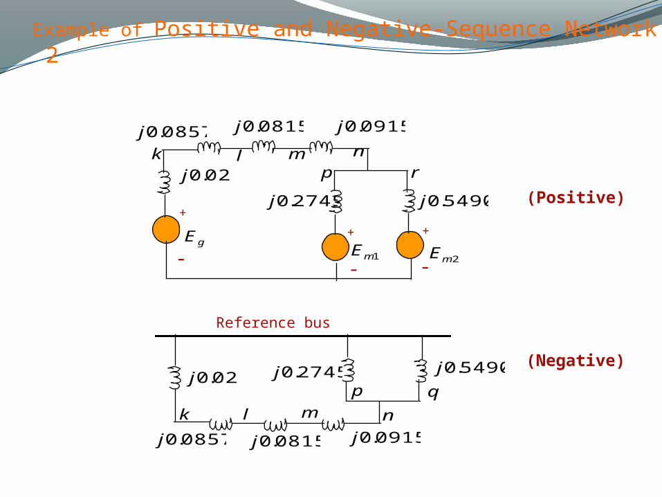
Example of Positive and Negative-Sequence Network 2
++
+
---
0857.0j 0915.0j0815.0j
5490.0j
02.0j
2745.0j
2mE1mEgE
k l m np r
0857.0j 0915.0j0815.0j
5490.0j02.0j 2745.0j
Reference bus
k l m n
p q
(Positive)
(Negative)
Page 53
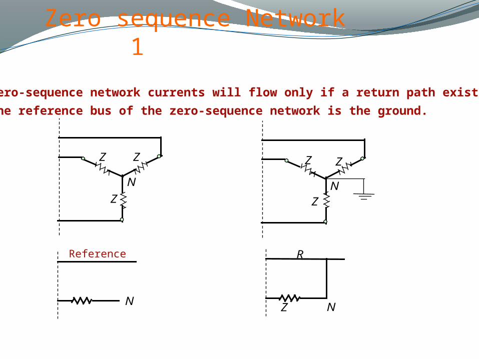
Zero sequence Network 1
1 . Zero-sequence network currents will flow only if a return path exists.
2 . The reference bus of the zero-sequence network is the ground.
ZZ
Z
N
Z
Z
Z
N
Z N
R
N
Reference
Page 54
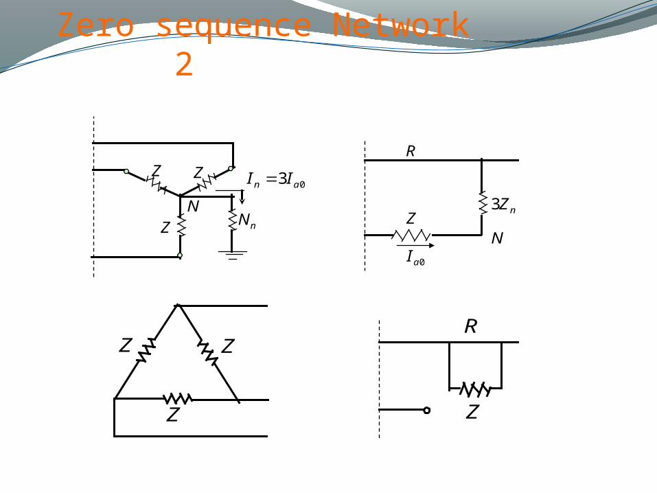
Zero sequence Network 2
Z
Z
Z
NZ
N
R
nN
03 an II
nZ3
0aI
Z Z
Z
R
Z
Page 55
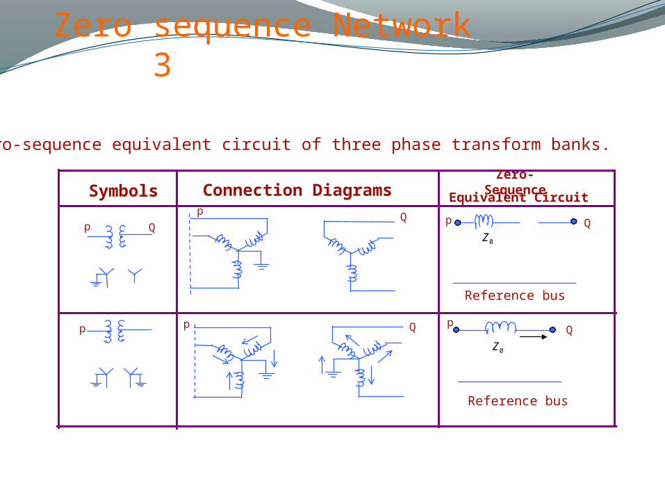
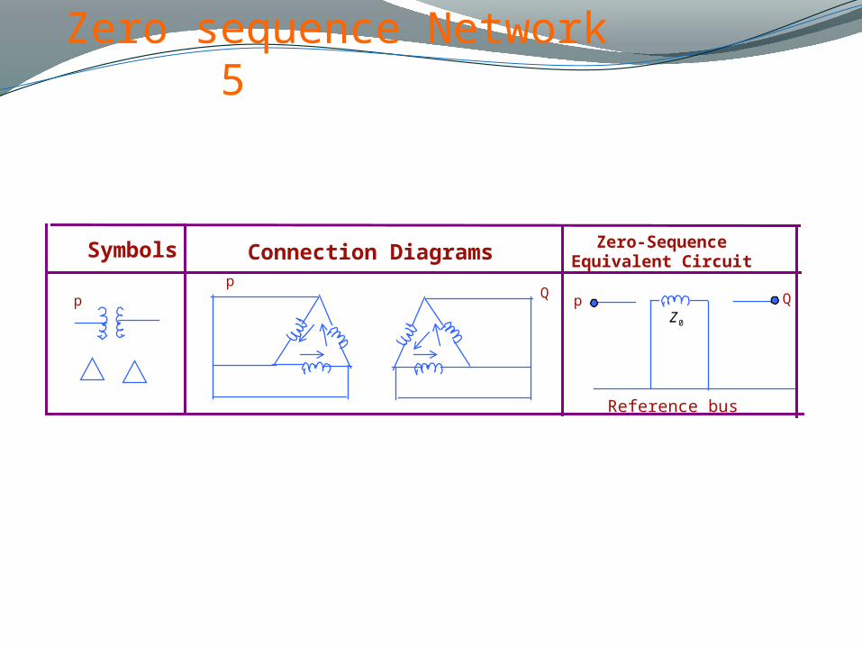
Zero sequence Network 3
Zero-sequence equivalent circuit of three phase transform banks.
Symbols Connection DiagramsZero-Sequence
Equivalent Circuit
p
pp
p p p
QQ Q
Q Q
0Z
0Z
Reference bus
Reference bus
Page 56
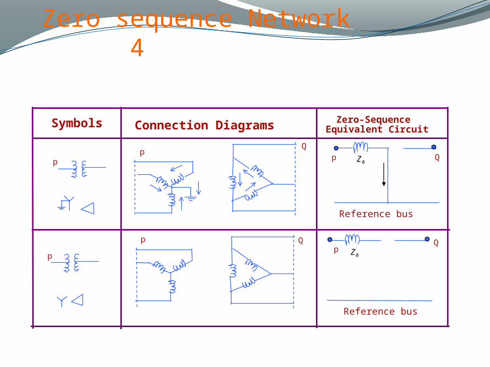
Zero sequence Network 4
Symbols Connection Diagrams Equivalent CircuitZero-Sequence
pp
p
p
pp
QQ
Q Q
0Z
0Z
Reference bus
Reference bus
Page 57
Zero sequence Network 5
Symbols Connection Diagrams Equivalent CircuitZero-Sequence
pp
pQ Q
0Z
Reference bus
Page 58
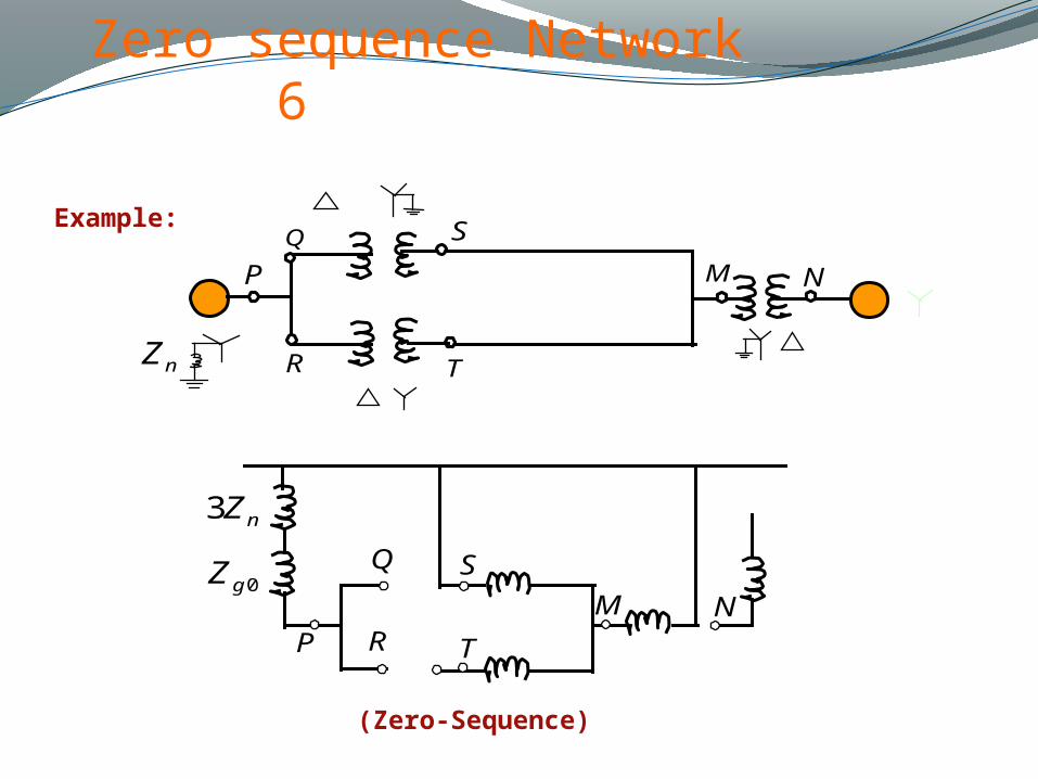
Zero sequence Network 6
nZ3
0gZQ
R
S
T
M NP
(Zero-Sequence)
Example:
nZ
Q S
P
R T
M N
Page 59
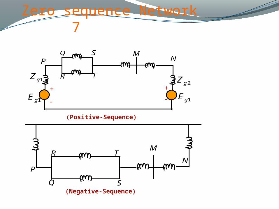
Zero sequence Network 7
1gZ
Q S
R T
MNP
2gZ
1gE 1gE++
--
Q
R TM
NP
S
(Positive-Sequence)
(Negative-Sequence)
Page 60
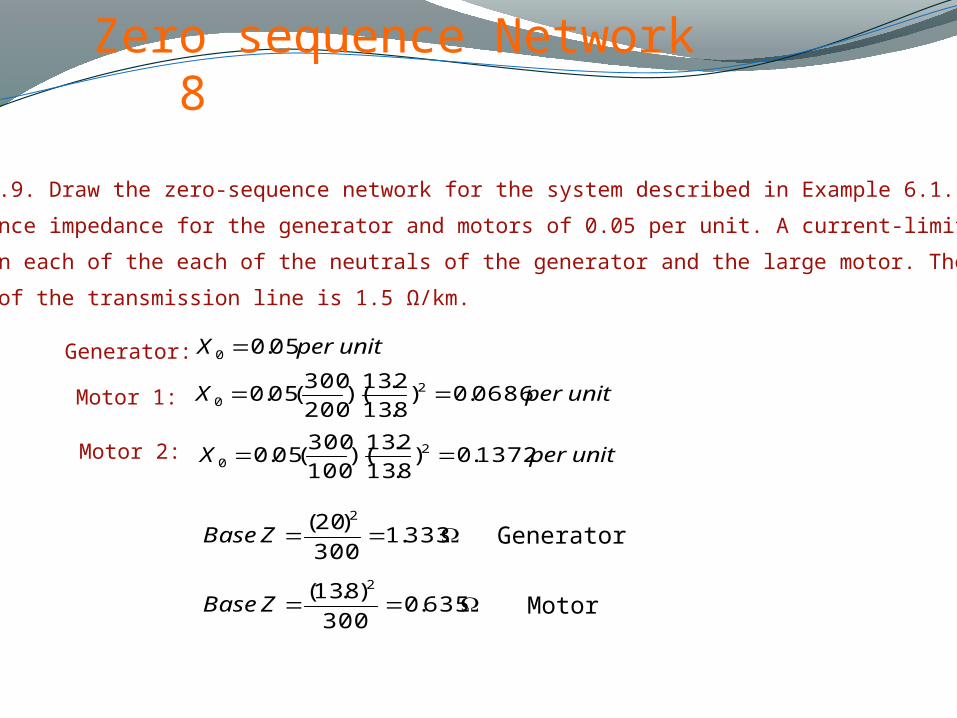
Zero sequence Network 8
Example 11.9. Draw the zero-sequence network for the system described in Example 6.1. Assume
zero-sequence impedance for the generator and motors of 0.05 per unit. A current-limiting reactor of
0.4 Ω is in each of the each of the neutrals of the generator and the large motor. The zero-sequence
reactance of the transmission line is 1.5 Ω/km.
Generator:
Motor 1:
Motor 2:
unitperX 05.00
unitperX 0686.0)8.13
2.13)(
200
300(05.0 2
0
unitperX 1372.0)8.13
2.13)(
100
300(05.0 2
0
333.1300
)20( 2
ZBase
635.0300
)8.13( 2
ZBase
Generator
Motor
Page 61
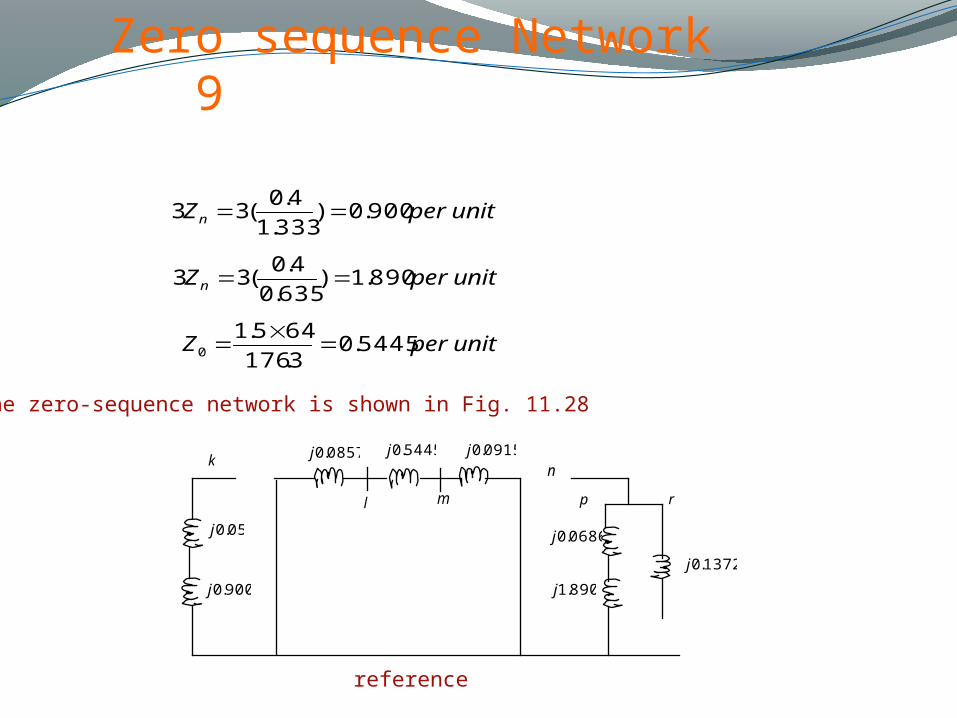
Zero sequence Network 9
unitperZn 900.0)333.1
4.0(33
unitperZn 890.1)635.0
4.0(33
unitperZ 5445.03.176
645.10
The zero-sequence network is shown in Fig. 11.28
05.0j
900.0j
0857.0j 5445.0j 0915.0j
l m
kn
p r
0686.0j
890.1j
1372.0j
reference