are the product of research anddevelopment ranging over manyyears. The know-how therebygained, coupled with highdemands with regard to quality,forms the guarantee for themanufacture of enginesfeaturing long service-life, highreliability, and low fuelconsumption.It goes without saying that thehigh demands regarding protec-tion of the environment are alsofulfilled.
Beware of Running Engine
Shut the engine down beforecarrying out maintenance orrepair work. Ensure that theengine cannot be accidentallystarted - accidents may otherwiseoccur. When the work iscomplete, be sure to refit anypanels and guards that have beenremoved.Never fill the fuel tanks while theengine is running. Observeindustrial safety regulations whenrunning the engine in an enclosedspace or underground.
Service and Maintenance
will also play a decisive role as towhether the engine fulfills to yoursatisfaction the demands youmake on it. Observance of theprescribed maintenance intervalsand careful carrying out of theservice and maintenance jobsare therefore essential.Particular attention must be givenwith regard to applicationsinvolving differing and harderoperating conditions ascompared with normaloperation.
Safety
When reading through
this Manual, you will findthis symbol marking all safetyinstructions and proceed withspecial care. Pass on these safetyinstructions to your operatingpersonnel.In addition, it is also necessary toobserve the official safety andaccident prevention rules.
DEUTZ Service
In case of operational troubles andqueries concerning spare parts,please contact your DEUTZ agent.Where necessary, our trainedspecialists will ensure a quick andprofessional repair, using DEUTZspare parts. Genuine DEUTZspare parts are alwaysmanufactured to the latesttechnical standards.More information on DEUTZSERVICE can be found at the end ofthis Operation Manual.
Asbestos
The seals and gaskets
used in this engine areasbestos-free. When carrying outmaintenance and repair work,please use appropriate spareparts.
5.1.1
MODEL DESIGNATION2.1 Model
2.1.1 Rating Plate
The model designation A, the engine serial number B and
the performance data are stamped on the rating plate. The
model and engine serial number must be given when ordering
parts.
2.1.2 Location of Rating Plate
The rating plate C is attached to the crankcase; depending
on the design, a second rating plate may be attached to the
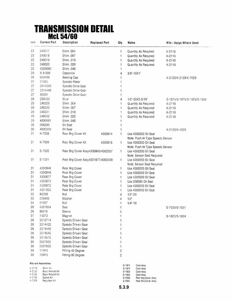
air duct.
2.1.3 Engine Serial Number
The engine serial number D is stamped onto the crankcase as
well as on the rating plate.
2.1.4 Numbering of Cylinders
The cylinders are numbered consecutively, beginning at the
flywheel end.
Adjustments to the regulator are to be carried out only by
authorized DEUTZ SERVICE - specialists.
5.1.2
ENGINE DESCRIPTION2.1 Model
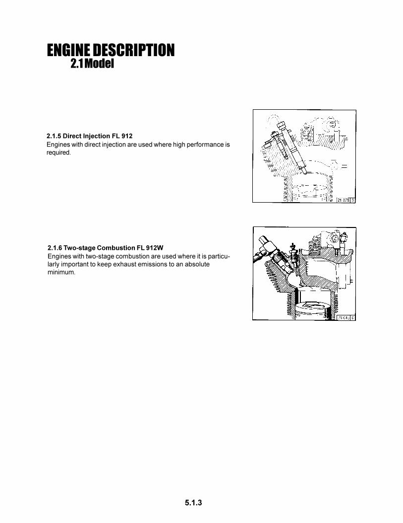
2.1.5 Direct Injection FL 912
Engines with direct injection are used where high performance is
required.
2.1.6 Two-stage Combustion FL 912W
Engines with two-stage combustion are used where it is particu-
larly important to keep exhaust emissions to an absolute
minimum.
5.1.3
ENGINE DESCRIPTION2.2 Engine Illustrations
2.2.1 Service Side F4L 912 1 Fan
2 V-belt (fan)
3 Injection pump
4 V-belt (alternator)
5 V-belt pully
6 Tension roller
7 Oil fill point
8 Oil pan
9 Oil drain plug
10 Fuel pump
11 Oil dipstick
12 Lube oil filter
13 Easy-change fuel filter
14 Air duct cover
15 Cylinder-head cover
2.2.2 Exhaust Side F4L 91216 Air intake pipe
17 Exhaust manifold pipe
18 Screen
19 Alternator
20 Starter
21 Engine mounting
22 Crankcase
23 Crankcase ventilation
5.1.4
ENGINE DESCRIPTION2.2 Engine Illustrations
15 Exhaust manifold line
16 Terminal housing
17 Starter
18 Crankcase ventilation
19 Oil pan
20 Alternator
21 Exhaust turbocharger
22 Air-intake pipe-exhaust
turbocharger
23 Charge-air line
2.2.4 Exhaust Side BF4L 913
1 Fan
2 V-belt (fan)
3 V-belt (alternator)
4 V-belt pully on crankshaft
5 Tension roller
6 Oil fill point
7 Oil drain plug
8 Fuel filter cartridge
9 Fuel pump with fuel precleaner
10 Injection pump
11 Oil dipstick
12 Lube oil filter cartridge
13 Air duct cover
14 Engine oil radiator cover
2.2.3 Service Side BF4L 913
5.1.5
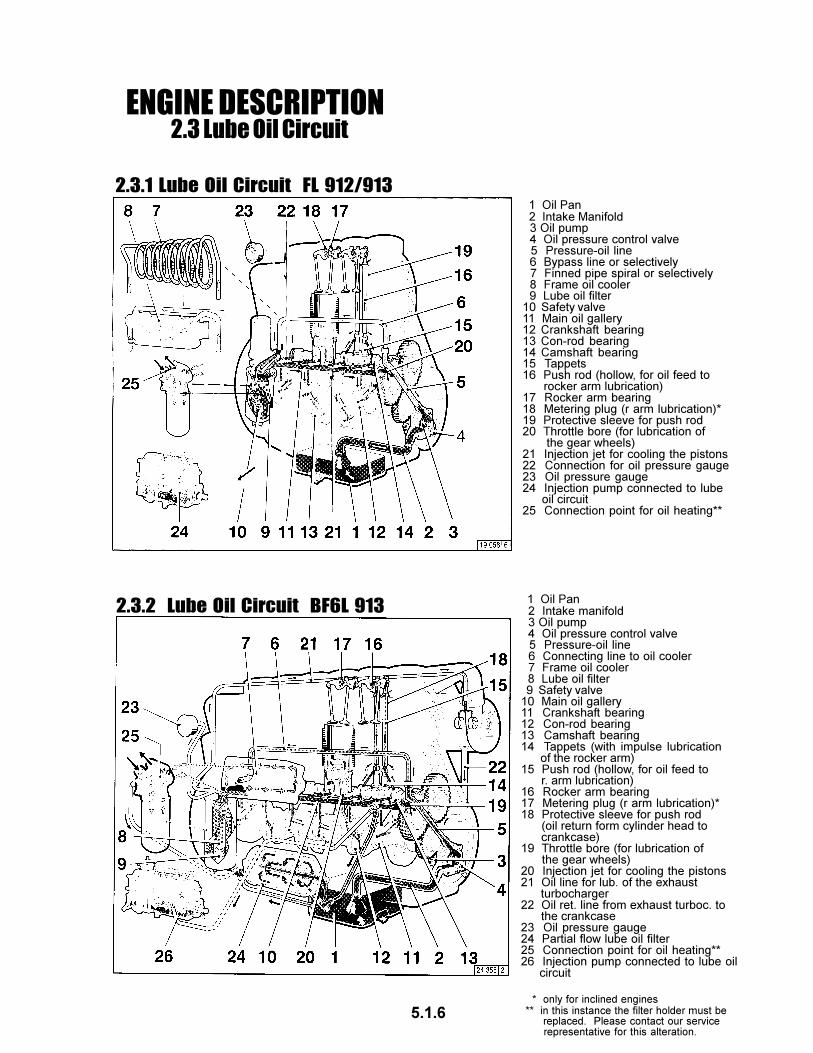
ENGINE DESCRIPTION2.3 Lube Oil Circuit
2.3.1 Lube Oil Circuit FL 912/913
2.3.2 Lube Oil Circuit BF6L 913
1 Oil Pan 2 Intake Manifold 3 Oil pump 4 Oil pressure control valve 5 Pressure-oil line 6 Bypass line or selectively 7 Finned pipe spiral or selectively 8 Frame oil cooler 9 Lube oil filter10 Safety valve11 Main oil gallery12 Crankshaft bearing13 Con-rod bearing14 Camshaft bearing15 Tappets16 Push rod (hollow, for oil feed to rocker arm lubrication)17 Rocker arm bearing18 Metering plug (r arm lubrication)*19 Protective sleeve for push rod20 Throttle bore (for lubrication of the gear wheels)21 Injection jet for cooling the pistons22 Connection for oil pressure gauge23 Oil pressure gauge24 Injection pump connected to lube oil circuit25 Connection point for oil heating**
1 Oil Pan 2 Intake manifold 3 Oil pump 4 Oil pressure control valve 5 Pressure-oil line 6 Connecting line to oil cooler 7 Frame oil cooler 8 Lube oil filter 9 Safety valve10 Main oil gallery11 Crankshaft bearing12 Con-rod bearing13 Camshaft bearing14 Tappets (with impulse lubrication of the rocker arm)15 Push rod (hollow, for oil feed to r. arm lubrication)16 Rocker arm bearing17 Metering plug (r arm lubrication)*18 Protective sleeve for push rod (oil return form cylinder head to crankcase)19 Throttle bore (for lubrication of the gear wheels)20 Injection jet for cooling the pistons21 Oil line for lub. of the exhaust turbocharger22 Oil ret. line from exhaust turboc. to the crankcase23 Oil pressure gauge24 Partial flow lube oil filter25 Connection point for oil heating**26 Injection pump connected to lube oil circuit
* only for inclined engines** in this instance the filter holder must be replaced. Please contact our service representative for this alteration.
5.1.6
ENGINE DESCRIPTION2.4 Fuel System Schematic
1 Fuel Tank
2 Fuel line from tank to fuel pump
3 Fuel supply pump
4 Easy-change fuel filter
5 Injection pump
6 Injection lines
7 Injection valves
8 Oil leakage line
9 Fuel overflow valve
10 Overflow valve
11 Fuel return line to tank A
Clearance: keep as far apart as
possible.
2.4.1 Fuel Circuit
5.1.7
2.5 Engine Cooling
1 Pressure-oil line from engine to
exhaust thermostat
2 Air line to exhaust thermostat
3 Exhaust manifold pipe
4 Exhaust thermostat
5 Control line to hydraulic coupling
6 Hydraulic coupling
7 Cooling fan
8 Cooling fan drive
9 Oil return line to crankcase
10 Ventilation line
11 Adjusting pin with special seal
2.5.1 Regulation of Coolant Flow using the
Exhaust Thermostat
2.5.2 Regulation of Coolant Flow using the
Exhaust Thermostat and Solenoid 1 Pressure-oil line from engine to
exhaust therostat
2 Air line to exhaust thermostat
3 Exhaust manifold pipe
4 Exhaust thermostat
5 Control line to hydraulic coupling
6 Hydraulic coupling
7 Cooling fan
8 Cooling fan drive
9 Oil return line to crankcase
10 Ventilation line
11 Adjusting pin with special gasket
12 Solenoid
ENGINE OPERATION
5.1.8
ENGINE OPERATION3.1 Commissioning
As a rule, engines are delivered empty
of oil. Pour lube oil into the oil filler
neck (arrow). For oil grade and
viscosity, see pg 4.1
Fill oil cup 1 of the oil bath air
cleaner with engine oil up to the
arrow. For oil grade and viscosity,
see 4.1
Use only commercial-grade diesel
fuel. For fuel grade see 4.2. Use
summer or winter-grade fuel, depend-
ing on the ambient temperature.
Oil may not be filled into
the dust collector of the
precleaner, if this is fitted.
Never fill the tank while the
engine is running. Keep
the filler cap area clean
and do not spill fuel.
l Loosen overflow valve 1 at the lower (larger)
hexagon.
l Loosen hand pump 2 at the notched grip 3 by
unscrewing by several turns to the left.
l Actuate hand pump 2 until bubble-free fuel is
emitted at the loosened overflow valve 1.
l Tighten overflow valve1, continuing to pump
at the same time.l Tighten grip 3.
l Loosen overflow valve 1 at the lower (larger)
hexagon.
l Actuate preliminary pump lever 2 against the
spring pressure until bubble-free fuel is
emitted at the loosened overflow valve 1.
3.1.1 Adding Engine Oil 3.1.2 Filling Oil Bath Air
Cleaner
3.1.3 Adding Fuel
3.1.4 Ventilation Model:
“Bosch” fuel pump
3.1.4 Ventilation Model:
“IMSA” fuel pump
l Tighten overflow valve 1, continuing to pump
at the same time.
5.1.9
ENGINE OPERATION3.1 Commissioning
3.1.5 Other Preparations
l Check battery and cable connections see 6.7.1
l Transport hooks
Remove if fitted (see 6.7.3)
l Trial run
After the engine has been prepared, let it run for
about 10 minutes without load.
During and after trial run
- Check the engine for leaks.
After the engine has been turned off
- Check the oil level, see 6.1.2
If necessary, top oil, see 3.1.1
Retension V-belts, see 6.5
l Breaking in
During the break-in phase - about 200 operating
hours - check the oil level twice a day. After the
engine is broken in, checking once a day will be
sufficient.
3.1.6 Additional Maintenance Work
l Change lube oil,
see 6.1.2
l Change oil filter cartridge,
see 6.1.3
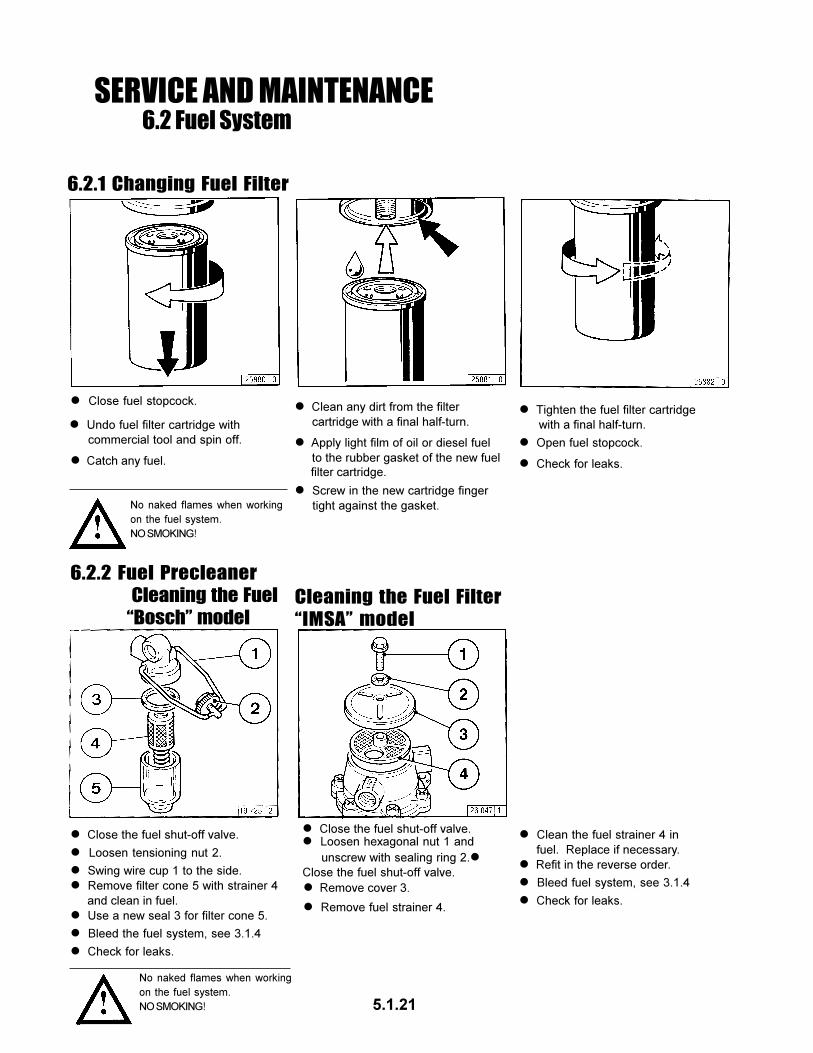
l Change fuel filter cartridge,
see 6.2.1
l Check V-belts and retension as necessary,
see 6.5
l Check the engine for leaks.
l Check the engine mount and adjust as
necessary, see 9.2
l Check valve clearance and adjust as
necessary, see 6.6.1
The following maintenance should be carried out
after 50-150 operating hours:
3.1.7 Selector Switch for Oil Heater
Position of selector switch for oil filter console with
oil heater connection:
Pos. 1: open
Pos. 2: closed
For engines without oil heating,
the selector switch is always
open
Pos. 2: to lock closed.
5.1.10
ENGINE OPERATION3.2 Starting
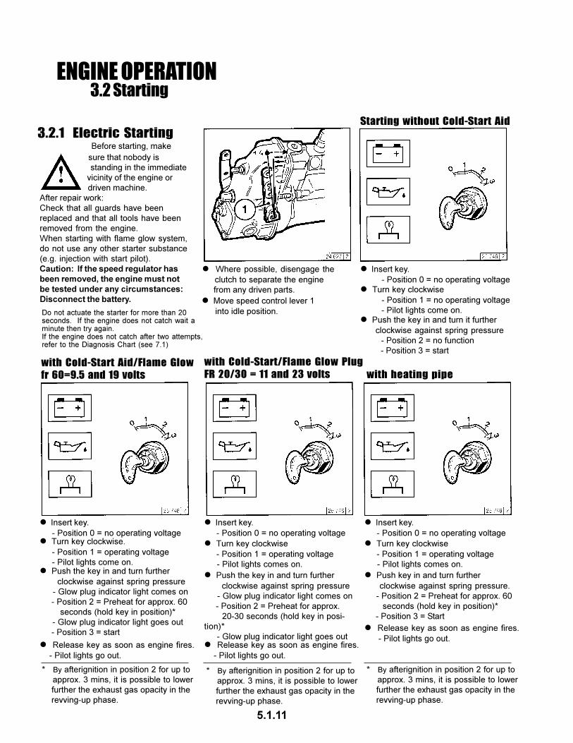
3.2.1 Electric Starting
with Cold-Start Aid/Flame Glow
fr 60=9.5 and 19 volts
with Cold-Start/Flame Glow Plug
FR 20/30 = 11 and 23 volts with heating pipe
l Where possible, disengage the
clutch to separate the engine
from any driven parts.
Before starting, make
sure that nobody is
standing in the immediate
vicinity of the engine or
driven machine.
After repair work:
Check that all guards have been
replaced and that all tools have been
removed from the engine.
When starting with flame glow system,
do not use any other starter substance
(e.g. injection with start pilot).
Caution: If the speed regulator hasbeen removed, the engine must notbe tested under any circumstances:Disconnect the battery.
Starting without Cold-Start Aid
l Move speed control lever 1
into idle position.
l Insert key.
- Position 0 = no operating voltagel Turn key clockwise
- Position 1 = no operating voltage
- Pilot lights come on.l Push the key in and turn it further
clockwise against spring pressure
- Position 2 = no function
- Position 3 = start
l Insert key.
- Position 0 = no operating voltagel Turn key clockwise.
- Position 1 = operating voltage
- Pilot lights come on.l Push the key in and turn further
clockwise against spring pressure
- Glow plug indicator light comes on
- Position 2 = Preheat for approx. 60
seconds (hold key in position)*
- Glow plug indicator light goes out
- Position 3 = start
l Release key as soon as engine fires.
- Pilot lights go out.
* By afterignition in position 2 for up to
approx. 3 mins, it is possible to lower
further the exhaust gas opacity in the
revving-up phase.
l Insert key.
- Position 0 = no operating voltage
l Push key in and turn further
clockwise against spring pressure.
- Position 2 = Preheat for approx. 60
seconds (hold key in position)*
- Position 3 = Start
l Turn key clockwise
- Position 1 = operating voltage
- Pilot lights comes on.
l Insert key.
- Position 0 = no operating voltage
l Turn key clockwise
- Position 1 = operating voltage
- Pilot lights comes on.
l Push the key in and turn further
clockwise against spring pressure
- Glow plug indicator light comes on
- Position 2 = Preheat for approx.
20-30 seconds (hold key in posi-
tion)*
- Glow plug indicator light goes outl Release key as soon as engine fires.
- Pilot lights go out.
* By afterignition in position 2 for up to
approx. 3 mins, it is possible to lower
further the exhaust gas opacity in the
revving-up phase.
* By afterignition in position 2 for up to
approx. 3 mins, it is possible to lower
further the exhaust gas opacity in the
revving-up phase.
l Release key as soon as engine fires.
- Pilot lights go out.
Do not actuate the starter for more than 20seconds. If the engine does not catch wait aminute then try again.If the engine does not catch after two attempts,refer to the Diagnosis Chart (see 7.1)
5.1.11
ENGINE OPERATION3.3 Monitering Systems
3.3.1 Engine Oil Pressure
Oil Pressure Pilot Light
l The oil pressure pilot light comes
on with operating voltage on and
engine off.
l The engine temperature gauge
pointer should remain in the green
sector most of the time. It should
rarely enter the yellow-green
sector. If the pointer enters the
orange sector, the engine is
overheating. Turn off and
establish the cause from the
Diagnosis Chart (see 7.1).
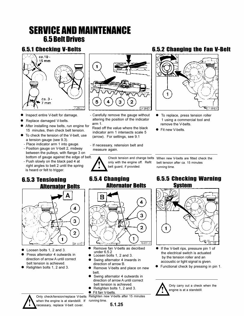
l If the V-belt rips, pressure pin 1 of the
electrical switch is actuated by the
tension roller and an acoustic or
light signal is given.
Switch off the engine immediately to prevent overheating.
l The oil pressure pilot light should
go out when the engine is running.
l The pointer must remain in the
green sector over the entire range.
Oil Pressure IndicatorOil Pressure Gauge
l The pointer must indicate
the minimum oil pressure (see 9.1).
Temperature Gauge
3.3.2 Engine Temperature 3.3.3 Cooling Fan Drive
5.1.12
3.4 Stopping
l Move speed control lever to low idle.
3.4.1 Mechanical Shutdown
3.4.2 Electrical Shutdown
l Operate shutdown lever 2 until the engine comes
to a stop. The charge pilot light and the oil pressure
pilot light will come on when the engine stops.
l Turn key counter-clockwise (to position 0) and
remove. The pilot lights will go out.
l Turn key counter-clockwise (to position 0) and
remove. The pilot lights will go out.
Ignition Key
5.1.13
ENGINE OPERATION
ENGINE OPERATION3.5 Operating Conditions
3.5.1 Winter Operation
3.5.2 High Ambient Temperatures
High Altitude
l Lube Oil Viscosity
- Select the oil viscosity (SAE grade) according to the ambient
temperature when the engine is started, see 4.1.2
- Increase oil change frequency when operating below
-10°C, see 6.1.1
l Diesel Fuel
- Use winter-grade diesel fuel for operation below 0°C, see 4.2.2
l Additional Maintenance Work
- Drain the sludge from the fuel tank once a week. (Unscrew the
sludge drain plug).
- If necessary, allow the oil in the oil bath air cleaner and the
engine oil to settle at the ambient temperature.
- Below -20°C, after removing the starter if necessary, smear the
ring gear on the fly wheel via the pinion bore from time or time
with cold-resistant grease, (e.g. Bosch grease FT 1 V 31).
l Cold-Start Aid
- At temperatures near or below freezing point, use glow plugs if
necessary, see 3.2.1. This not only lowers the starting limit
temperature, but provides easier starting at temperatures
normally not requiring a starting aid.
l Battery
- Efficient cold starting requires a healthy battery, see 6.7.1
- The starting limit temperatures can be lowered by 4-5 °C by
heating the battery up to about +20°C. (To do so, remove the
battery and store in a warm place.)
l As the altitude and ambient temperature rise, the density of air
tends to decrease, which affects the maximum power output of
the engine, the exhaust gas quality and, in extreme cases, the
starting behavior. Under transient conditions, the engine can be
used at altitudes up to 1000m and temperatures up to 30°C. If
the engine is to operate under more severe conditions (at higher
altitudes or temperatures), it will be necessary to reduce the
injected fuel quality and thus, engine power.
l If you have any doubts about engine operation under these or
similar conditions, ask your engine or equipment supplier
whether
the engine has been derated in the interests of reliability, service
life and exhaust gas quality (smoke). Otherwise contact
DEUTZ SERVICE.
5.1.14
OPERATING MEDIA4.1 Lube Oil
4.1.1 Quality Grade
4.1.2 Viscosity
Lube oils are differentiated according to their
performance and quality class. In commom use
are specifications named after the API (American
Petroleum Institute) and ACEA (European Engine
OIl Sequences).
Approved API Oils:
At least: CF-4
Approved ACEA Oils:
At least E1-96
As the viscosity of the lube oil is dependent on
temperature, the choice of SAE grade should be
governed by the ambient temperature prevailing at
the engine operating site. Optimum operating
behaviour will be attained if you take the accompa-
nying oil viscosity diagram as a guide.
Should the temperature fall temporarily below the
limits of SAE grade selected, cold starting may be
affected but the engine will not be damaged.
In order to keep wear to a minimum, do not exceed
application limits for extended periods of time.
Oil changes dictated by the seasons can be
avoided by using multi-grade lube oils. Multi-grade
oils - particularly light flowing oils - also reduce fuel
consumption.
Oil change intervals, see 6.1.1
Oil capacities, see 9.1
5.1.15
OPERATING MEDIA4.2 Fuel
l DIN EN 590
Use commercially available diesel fuel with less
than 0.5% sulphur content. If the sulphur content is
higher than 0.5% oil change intervals should be
reduced, see 6.1.1
The following fuel specifications / standards are
approved:
4.2.1 Quality Grade
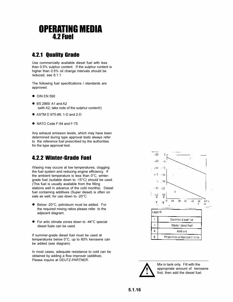
4.2.2 Winter-Grade Fuel
l BS 2869: A1 and A2
(with A2, take note of the sulphur content!)
l ASTM D 975-88; 1-D and 2-D
l NATO Code F-54 and F-75
Any exhaust emission levels, which may have been
determined during type approval tests always refer
to the reference fuel prescribed by the authorities
for the type approval test.
Waxing may occure at low temperatures, clogging
the fuel system and reducing engine efficiency. If
the ambient temperature is less than 0°C, winter-
grade fuel (suitable down to -15°C) should be used.
(This fuel is usually available from the filling
stations well in advance of the cold months). Diesel
fuel containing additives (Super diesel) is often on
sale as well, for use down to -20°C.
If summer-grade diesel fuel must be used at
temperatures below 0°C, up to 60% kerosene can
be added (see diagram).
In most cases, adequate resistance to cold can be
obtained by adding a flow improver (additive).
Please inquire at DEUTZ-PARTNER.
l Below -20°C, petroleum must be added. For
the required mixing ratios please refer to the
adjacent diagram.
l For artic climate zones down to -44°C special
diesel fuels can be used.
Mix in tank only. Fill with the
appropriate amount of kerosene
first, then add the diesel fuel.
5.1.16
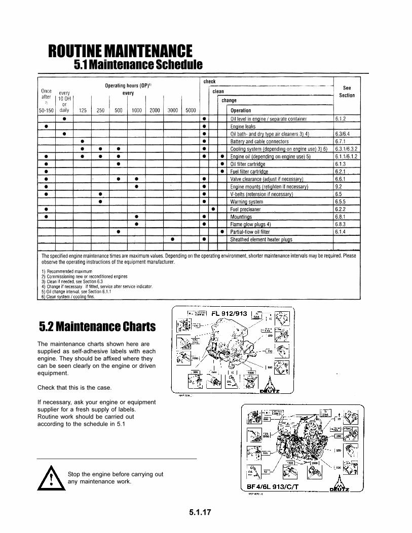
ROUTINE MAINTENANCE5.1 Maintenance Schedule
5.2 Maintenance Charts
The maintenance charts shown here are
supplied as self-adhesive labels with each
engine. They should be affixed where they
can be seen clearly on the engine or driven
equipment.
Check that this is the case.
If necessary, ask your engine or equipment
supplier for a fresh supply of labels.
Routine work should be carried out
according to the schedule in 5.1
Stop the engine before carrying out
any maintenance work.
5.1.17
ROUTINE MAINTENANCE5.3 Completed Maintenance Jobs
5.1.18
SERVICE AND MAINTENANCE6.1 Lubrication System
6.1.1 Oil Change Intervalsl The oil change intervals are
If a V-belt is worn or damaged, both belts in the set
must be replaced. The difference in the length of the
new V-belts may not exceed 0.15%.
Only check or replace V-belts when the engine is at
a standstill. If necessary replace V-belt cover.
When new V-belts are fitted, check the belt tension
after approx. 15 minutes running time.
5.1.26
l Adjust valve clearance if necessary:
- Release locknut 4.
- Use screwdriver 7 to turn setscrew 5 so
that the correct clearance is attained after
locknut 4 has been tightened.
l Check valve clearance 1 between rocker
arm / tappet contact face 2 and valve stem
3 with feeler gauge 6 (there should be only
slight resistance when feeler blade is
inserted).
For permissible valve clearance, see 9.1
l Remove the cylinder head cover.
l Before adjusting valve clearance, allow
engine to cool down for at least 30 minutes.
The oil temperature should be below 80°C.
l Position crankshaft as per schematic
6.6.1 Checking / Adjusting
Valve Clearances
6.6.1.1 Valve Clearance
Adjustments Schematic
l Check and adjust valve clearance on all
remaining cylinders.
Only inclined engines are fitted with an additional oil jet
for lubrication of the bearing. Any adjustments must
be carried out in an authorized specialist workshop.
SERVICE AND MAINTENANCE6.6 Adjustments
l Replace cylinder head cover (use new gasket
if needed).
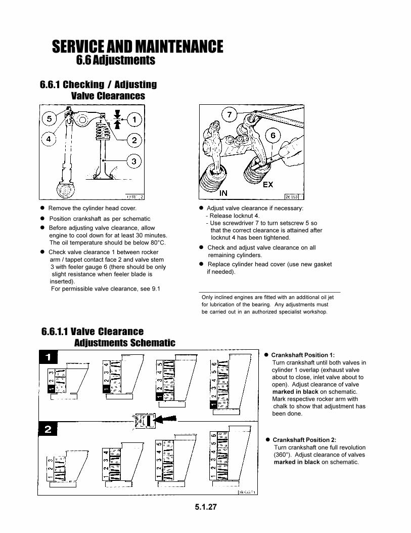
l Crankshaft Position 1: Turn crankshaft until both valves in
cylinder 1 overlap (exhaust valve
about to close, inlet valve about to
open). Adjust clearance of valve
marked in black on schematic.
Mark respective rocker arm with
chalk to show that adjustment has
been done.
l Crankshaft Position 2: Turn crankshaft one full revolution
(360°). Adjust clearance of valves
marked in black on schematic.
5.1.27
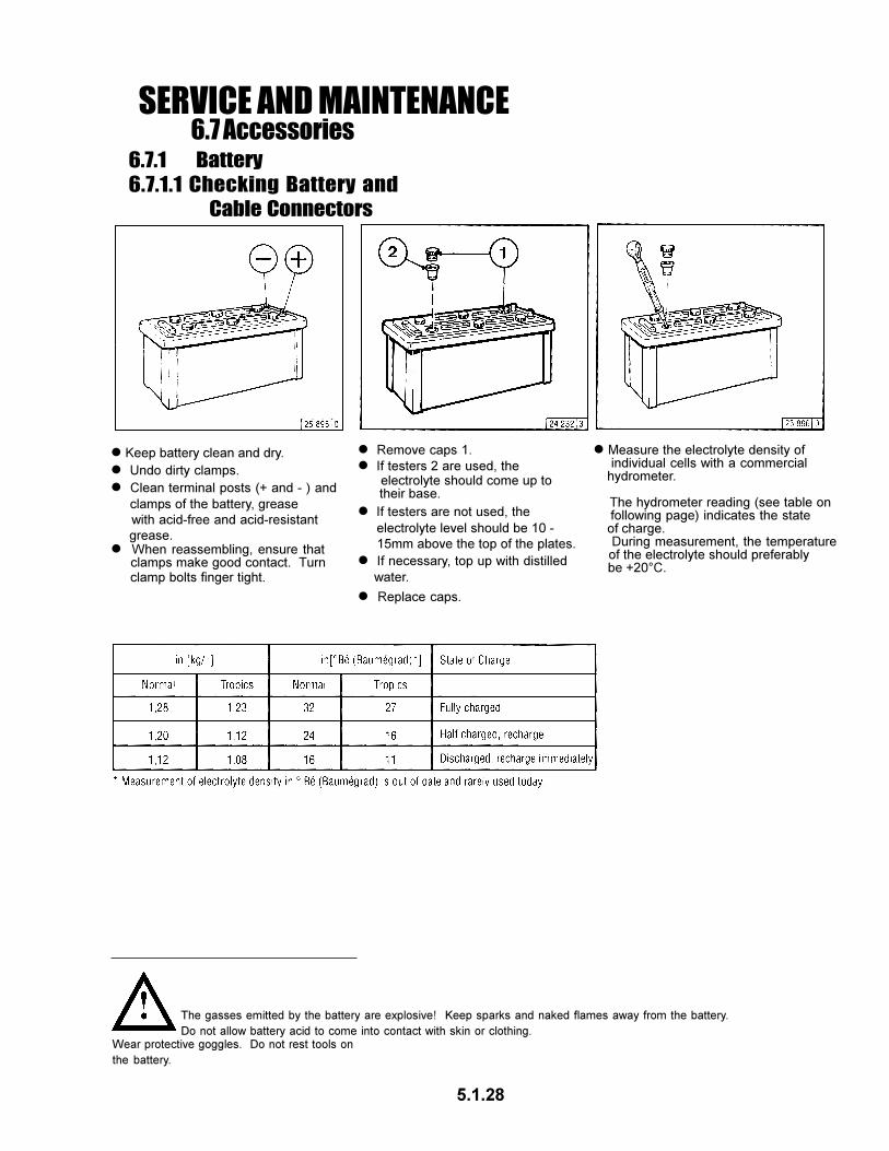
6.7.1 Battery
6.7.1.1 Checking Battery and
Cable Connectors
SERVICE AND MAINTENANCE6.7 Accessories
l Remove caps 1.
l If testers are not used, the
electrolyte level should be 10 -
15mm above the top of the plates.
l If testers 2 are used, the electrolyte should come up to their base.
l If necessary, top up with distilled
water.
l Replace caps.
l Measure the electrolyte density of individual cells with a commercial hydrometer.
The hydrometer reading (see table on following page) indicates the state of charge. During measurement, the temperature of the electrolyte should preferably be +20°C.
The gasses emitted by the battery are explosive! Keep sparks and naked flames away from the battery.
Do not allow battery acid to come into contact with skin or clothing.Wear protective goggles. Do not rest tools on
the battery.
5.1.28
l Keep battery clean and dry.
l Undo dirty clamps.
l Clean terminal posts (+ and - ) and
clamps of the battery, grease
with acid-free and acid-resistant
grease.l When reassembling, ensure that clamps make good contact. Turn clamp bolts finger tight.
l Never disconnect the cable between battery, alternator and regulator while the engine is running.
l Be sure not to confuse the battery
terminals.
l If, however, it is necessary to start and operate the engine without the battery, disconnect the regulator from the alternator before starting.
l After transportation and before commissioning of the engine: Remove transport eyes 2.l In case of electric welding connect
ground terminal on the welder
directly to the piece being welded.
l Always use proper lifting tackle 1 when transporting the engine.
l Replace defective bulb of the charge pilot lamp immediately.
l The habit of touching a lead against the
frame to check whether it is live must
under no circumstances be used with
three-phase electrical systems.
l When washing the engine, cover up the alternator and regulator.
Use only the correct lifting tackle.
6.7.2 Three-Phase
Alternator
6.7 Accessories
SERVICE AND MAINTENANCE
6.7.3 Lifting Tackle
5.1.29
6.8 Engine CleaningSERVICE AND MAINTENANCE
6.8.1 Cleaning the Engine
l Switch off the engine.
l Remove engine covers, cooling air hoods. Replace following cleaning and before test run.l Cover electrical / electronic components / connections (e.g. alternator, starter, regulator, solenoid).
l Pass compressed air through the engine, being careful with the cooler and cooling fins (start at the exhaust side). Remove dirt which has been blown into the inner compartment.
l Spray engine with commercial
cold-cleaning compound and
leave to work for approx. 10
minutes.
l Drive the engine warm so that remaining water evaporates.
l Drive the engine warm so that
remaining water evaporates.l Spray engine clean with water jet and if necessary repeat procedure.
l Cylinder head cover 1 l When functioning correctly, the
heating pipe heats up via the
integrated heating coil when
starting the preheating
- heating pipe
- air intake pipe
l Air-intake pipe 2
l Move speed adjustment lever and shut-off lever to “stop” position.
l Press in key and turn further
clockwise against the spring
pressure.
- Position 2 = preheat, hold for
approx. 1 minute.
- Preheat lamp lights up.
l Exhaust line 3
l Coupling sleeves
l Rotate engine with starter, key on
switch position 3.
l Engine mounting 4
6.9.2 Checking the
Function of the
Heating Pipe
6.9.3 Checking the
Function of the Flame
Glowing System
l When functioning correctly, intake pipe 4 heats up in the vicinity of flame glow plug 2 when starting with preheating.
l Loosen pipe connection 1.
l Fuel must be emitted at loosened pipe connection. Otherwise have the system, solenoid 3, checked by a specialist.
l Turn key clockwise. - Postion 1 = operating voltage - Pilot light comes on.
l Insert key - Position 0 = no operating voltage
l Remove flame glow plug 2.
l Loosen pipe connection 1.
l Rotate engine with starter, key in switch postition 3.
l Fuel must be emitted at flame glow
plug 2, replace plug 2 as necessary.
l Refit flame glow plug 2 on fuel line. Keep clear of rotating parts.
l Use sealant DEUTZ DW 47 when
fitting flame glow plug 2.
Test Stage 1: Test Stage 2: Test Stage 3:
Collect any leaked fuel and
dispose of in an environmentally
friendly fashion.l Otherwise flame glow plug
defective or power interrupted.
5.1.31
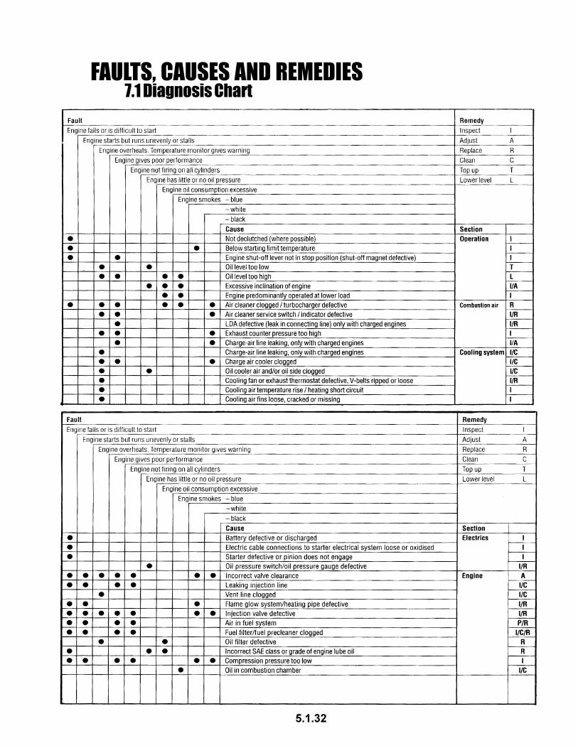
7.1 Diagnosis ChartFAULTS, CAUSES AND REMEDIES
5.1.32
l Drain fuel from tank.
If the engine is to remain idle for an extended period of time, itis necessary to take protective measures to prevent rustformation. The preservative measures described here willprotect the engine for up to 6 months. The procedure will haveto be reversed before the engine is recommissioned.
l Recommended cleansing agent to remove preservatives
when recommissioning engine:
- Petroleum benzine (hazardous materials class A3)
l Anti-corrosion oils to specification: - MIL-L-21260B - TL 9150-037/2 - Nato Code C 640 / 642
l If necessary, clean oil bath cleaner, see 6.4.3, and fill with anti-corrosion oil.
l Run engine until warm, then turn off.
l Drain engine oil, see 6.1.2 and fill with anti-corrosion oil.
l Clean engine (with cold cleansing agent if preferred) using high pressure equipment.
l Make up a mixture of 90% diesel fuel and 10% anti-corrosion
oil, and refill fuel tank.
8.1.1 Preserving Engine
8.1ENGINE PRESERVATION
8.1.2 Removing Engine Preservatives
l Spray grooves on V-belts pulleys with anti-corrosion spray.
l Turn engine off.
l Turn engine over manually several times to preserve the cylinders and combustion chamber. When rotating with starter, place shut-off lever in stop position.
l Run engine for about 10 minutes.
l Remove plugs from intake port and exhaust port.
l Remove V-belts and store dry in wrapped condition.
l Install V-belts. Retension after brief operation if necessary, see 6.5
l Set the engine in operation.
l Remove anti-corrosion agent from grooves in V-belt pulleys.
5.1.33
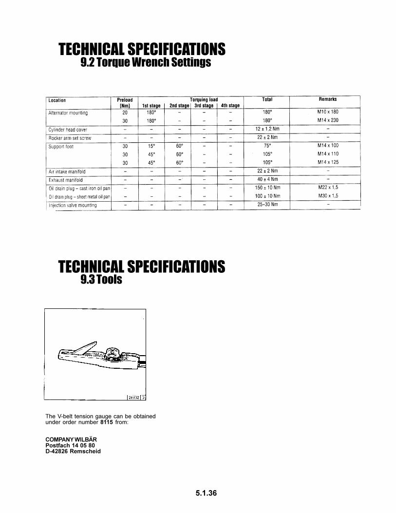
l Drain fuel from tank.
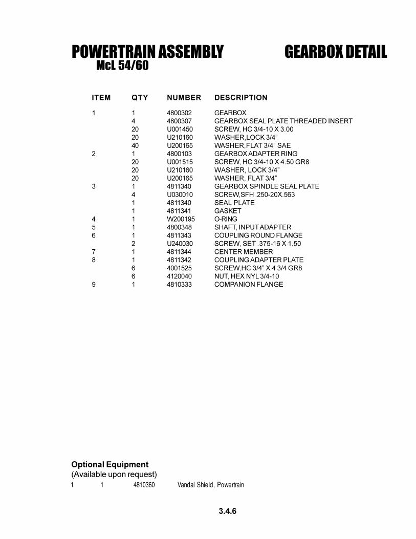
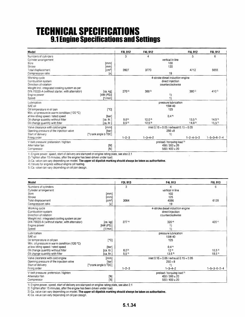
9.1 Engine Specifications and SettingsTECHNICAL SPECIFICATIONS
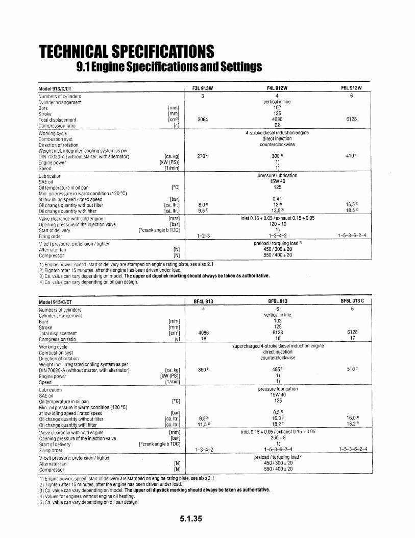
5.1.34
9.1 Engine Specifications and SettingsTECHNICAL SPECIFICATIONS
1. Engaging the clutch against an immovable load, will cause premature failure of the clutch.
Do not cycle the clutch (on/off/on/off etc.) with augers under-load.
COLD WEATHER OPERATION
Cold weather affects the operation of the boring machine. Cold hydraulic fluid causes sluggish machine
performance and can contribute to the premature failure of some machine components. Before starting to
bore, the machine and hydraulic fluid must be at operating temperature (i.e. the machine must be warmed-
up before boring).
Warm-up procedure:
1. Start the machine and let it run at idle for 1-2 minutes.
2. Slowly increase the engine rpm to about 1/2 to 3/4 full throttle
3. Allow the engine to run at this higher speed for 4-5 minutes
4. Extend and retract the thrust cylinders to warm up the hydraulic fluid.
5. Occasionally running the machine over relief will help to reduce the warm-up time.
Only after the machine is warmed up should you begin to bore!
Hydraulic Clutch Operation:
SLUGGISH OR DELAYED APPLY TIME FOR THE CLUTCH CAN CAUSE PREMATURE FAILURE.
The apply time for the clutch (the time it takes to build full pressure) is critical to the operation of the
machine. Normal clutch apply time is less than 2 seconds. If the apply time is greater than 2 seconds,
wait until the oil temperature increases before boring. The apply time can be monitored by the pressure
gauge on the console panel. Cycle the clutch during warm-up, waiting 10 seconds between engagements.
WHEN APPLYING THE CLUTCH DURING THE WARM-UP PERIOD, THE TRANSMISSION MUST BE IN
NEUTRAL. Do not cycle the clutch during warm-up while coupled to loaded augers. Boring with an
extended clutch apply time will cause premature failure of the clutch.
The hydraulic clutch operating system has 2 switches.
1. O.P.C. Switch
2. Clutch Switch
Both the O.P.C. switch and the Clutch switch must be in the “ON” position
before the clutch will operate. If the clutch does not operate, make sure that both of these
switchs are “ON”.
The hydraulic pressure is set at the factory for 225 psi. This pressure must be maintained for proper
operation. DO NOT operate the clutch if the clutch pressure gauge is reading below 150 psi. Too low an
operating pressure will result in premature clutch failure.
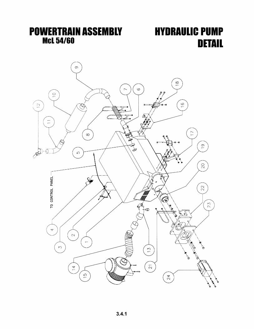
HYDRAULIC CLUTCHMcL 54/60
6.1.1
HYDRAULIC CLUTCHMcL 54/60
COLD WEATHER OPERATION
Hydraulic Fluid:
Use the alternate hydraulic fluid for the following:
- To reduce warm-up time before boring.
- When consistently boring in cold weather.
Standard hydraulic fluid:
- ISO grade #46 with anti-wear additives.
- 76 Unax AW #46
- Or equivalent
Alternate hydraulic fluid:
- ISO grade #32 Wide Temperature Range oil with anti-wear additives.
- 76 Unax AW-WR #32
- Or equivalent
Consult McLaughlin for more information.
6.1.2
HYDRAULIC CLUTCHMcL 54/60
6.2 TROUBLESHOOTING
DANGER: DO NOT OPERATE MACHINE IF CLUTCH IS NOT OPERATING PROPERLY. DEATH OR
SERIOUS INJURY WILL RESULT.
The hydraulic clutch supplied with this machine is a dry-running, self-adjusting, twin-disk clutch. The
clutch requires very little maintenance. Following is a list of symptoms which may require servicing the
clutch.
1. Contamination
The clutch is designed to run in a dry environment. However, the clutch housing can become contami-
nated. Contamination can result from dirt or sandy grit, oils, or water (which causes rust) entering the
clutch housing.
Clean the disc pack kit with kerosene to restore to normal condition.
2. Drag in Neutral
It is natural for a twin-disc clutch to have a small amount of drag in the disengaged state. The drag should
be more noticeable at low engine speeds and in low transmission gears.
A. New machines or rebuilt clutches
There is an indeterminate break-in time required for new clutches. Once a clutch has been working for a
while, it should seat itself and neutral drag should be at a minimum.
B. Abrupt changes in clutch drag
If the drag in the clutch abruptly increases, it may be due to insufficient spring tension between the clutch
discs. Weaker springs cause more drag between the discs of the clutch. Excessive heat, generated in
the clutch by cycling the clutch or by applying the clutch against locked augers, will weaken the springs
and cause excessive nuetral drag.
Replace disc pack kit and inspect all other components for damage and replace as necessary.
Refer to the Clutch Components and Disassembly/Assembly section of this manual for components and
proper clutch service procedures.
6.2.1
PAGE LEFT BLANK
7.1.0
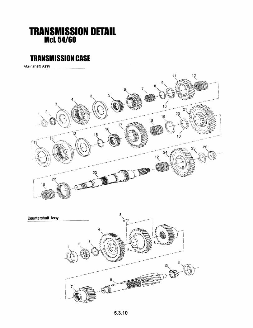
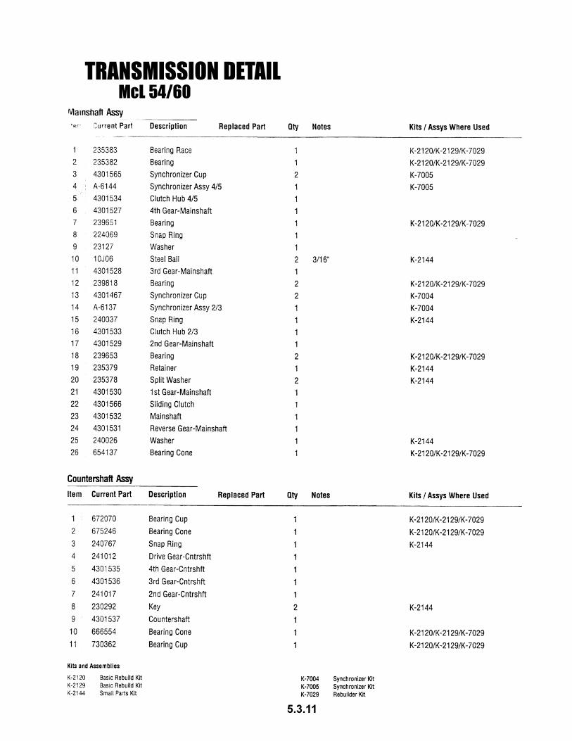
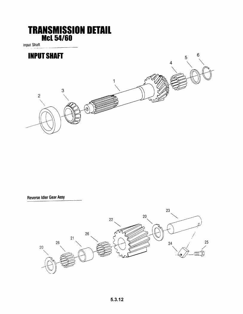
SERVICE AND REPAIR INSTRUCTIONSMcL-54/60
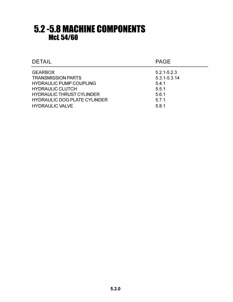
DETAIL PAGE
MACHINE SPLIT 7.1.1
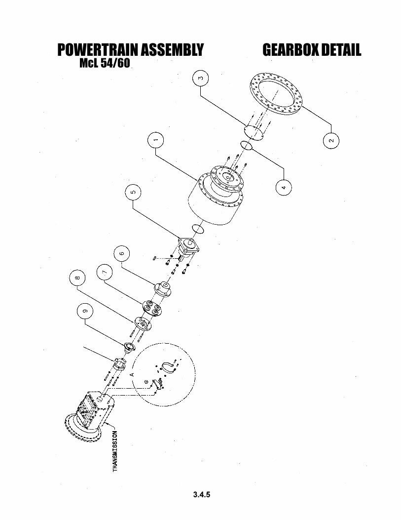
COUPLING (PUMP & GEARBOX) 7.2.1
HYDRAULIC PUMP COUPLING 7.3.1
DOG PLATE 7.4.1
THRUST CYLINDER 7.5.1
HYDRAULIC CLUTCH 7.6.1
PUMP SETTINGS AND ADJUSTMENTS 7.7.1
MAIN THRUST VALVE ADJUSTMENT 7.8.1
McL-54/60SERVICE AND REPAIR INSTRUCTIONS
DANGER:Crushing weight will cause serious injury.
Place machine on solid surface to prevent
rollover or falling.
CAUTION:Do not modify this machine. Use only autho-
rized McLaughlin repair parts. Failure to
comply may result in serious injury. Service
this equipment according with maintenance instructions
in this manual.
WARNING:Moving parts. Keep all guards in place.
Shut down engine before service or
maintenance. Being caught in machinery could
cause serious injury.
CAUTION:High Pressure. Leaking hydraulic fluid
under pressure may penetrate and
cause serious injury. Check for leaks with
cardboard. Relieve pressure before working on
any system.
7.1 Machine Split Instructions
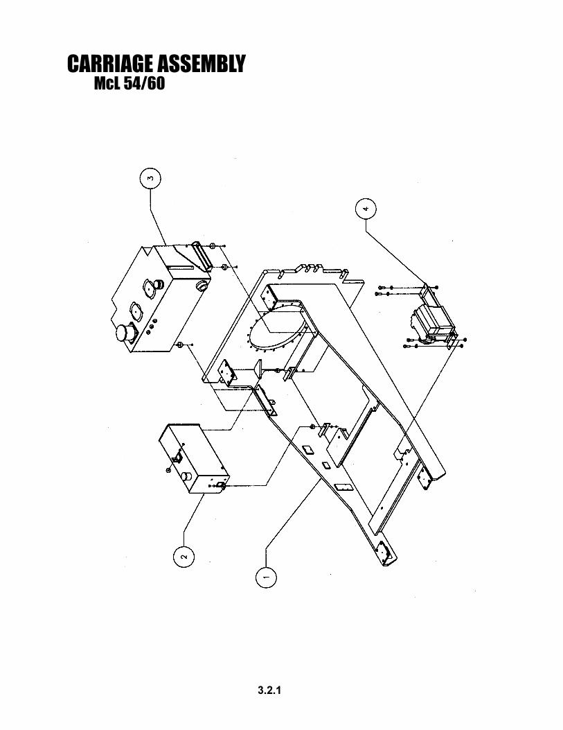
A. Removing the Carriage
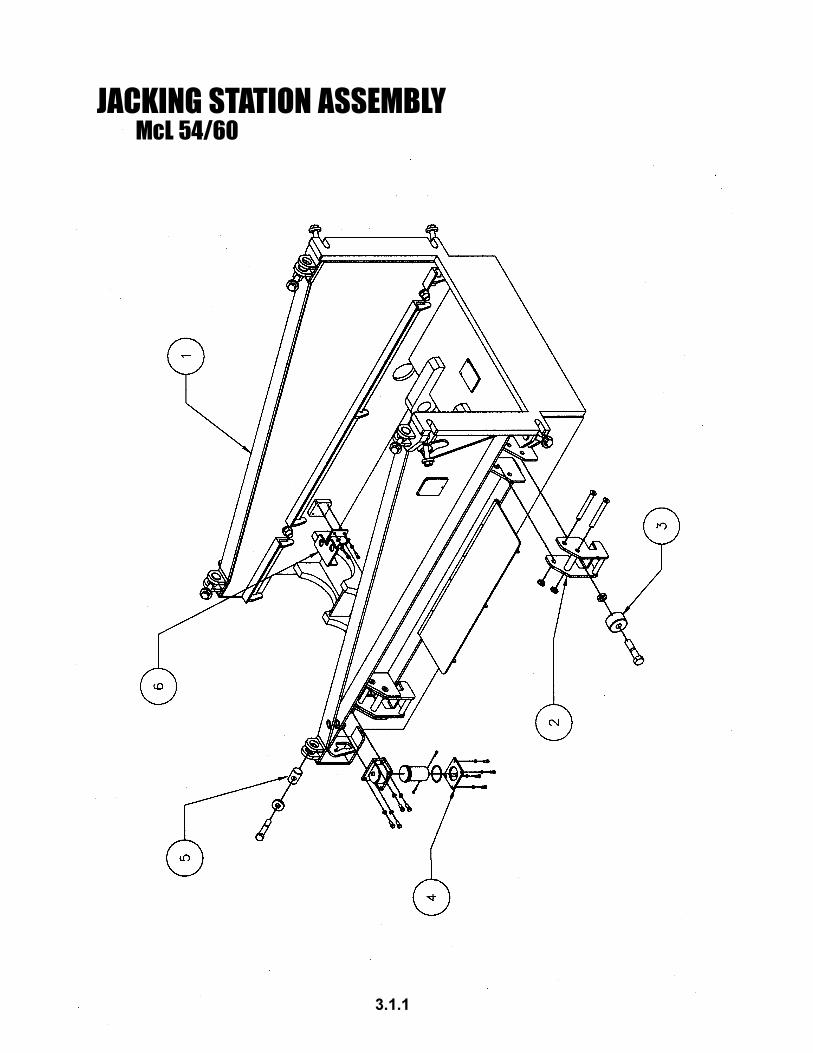
Important Note: If the jacking station is to be re-
moved from the track, then do the following, in se-
quence, before removing, the carriage:
1.) Fully retract dog pins.
2.) Close dog pin valve while pins are
retracted.
3.) Turn OFF dog pin switch.
4.) Fully retract thrust cylinders.
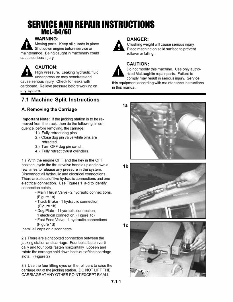
1.) With the engine OFF, and the key in the OFF
position, cycle the thrust valve handle up and down a
few times to release any pressure in the system.
Disconnect all hydraulic and electrical connections.
There are a total of five hydraulic connections and one
electrical connection. Use Figures 1 a-d to identify
connection points.
• Main Thrust Valve - 2 hydraulic connec tions.
(Figure 1a)
• Track Brake - 1 hydraulic connection
(Figure 1b)
• Dog Plate - 1 hydraulic connection,
1 electrical connection. (Figure 1c)
• Fast Feed Valve - 1 hydraulic connections
(Figure 1d)
Install all caps on disconnects.
2.) There are eight bolted connection between the
jacking station and carriage. Four bolts fasten verti-
cally and four bolts fasten horizontally. Loosen and
rotate the carriage hold down bolts out of their carriage
slots.. (Figure 2)
3.) Use the four lifting eyes on the roll bars to raise the
carriage out of the jacking station. DO NOT LIFT THE
CARRIAGE AT ANY OTHER POINT EXCEPT BY ALL
7.1.1
1a
1b
1c
SERVICE AND REPAIR INSTRUCTIONSMcL-54/60
7.1.2
1d
2
3
FOUR LIFTING EYES. The weight of the carriage is
not evenly distributed. Use caution when lifting. Make
sure all hoses and wires are free from machine compo-
nents before separating the machine. Place the
carriage on a flat and stable surface.
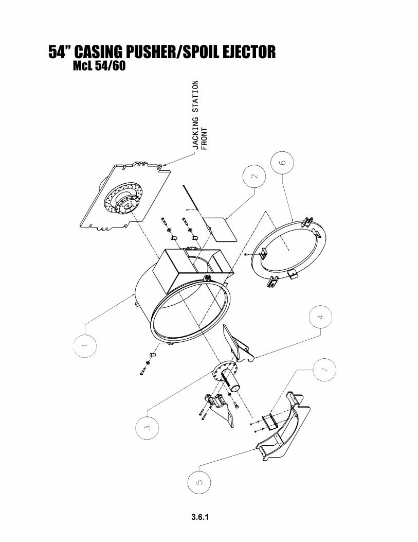
B. Removing the Casing Pusher
1.) The casing pusher has four bolted connections.
Loosen, but do not remove the bolts. Rotate the bolts
out of the carriage slots.
2.) The casing pusher must be moved far enough
horizontally in order to clear the chuck before it can be
lifted vertically from the machine.
C. Removing the Jacking Station from Track
1.) The procedures from “Section I - Important Note”
must be followed prior to removing the jacking station
from the track.
2.) Raise and pin the track hold downs in the retracted
position. (Figure 3)
3.) Use the four lifting eyes in the jacking station to lift
the jacking station out of the track. The weight of the
jacking station is not evenly distributed. Use caution
when lifting.
4.) Place the jacking station on a flat and stable
surface.
D. Assemble Carriage to Jacking Station
1.) Verify all hoses and wires are free from being
pinched or crushed when placing the carriage into the
jacking station. Be careful not to damage machine
components when placing the carriage.
2.) Once the carriage is resting in the jacking station,
fasten the four horizontal bolts first. This will secure
the carriage front plate against the jacking station’s
thrust wall. Now fasten the four vertical bolts.
3.) Make the six hydraulic and one electrical connec-
tion.
4.) Fully open dog pin valve.
7.2 Coupling Instructions
Tools Required: - 5/8” hex bit socket and ratchet
- 1 1/8” socket or wrench
- 3/16” Allen-head T-handle wrench
- McLaughlin Tool #4810321
1. REMOVAL
Remove the coupling guard from mounted position on the transmission.
Remove the two bolts that fasten the coupling hub to the coupling. Loosen the set screw over the
key in the coupling hub. Slide the coupling hub up the input adapter shaft to create enough clearance
for removing the coupling center member.
Next, fit McLaughlin tool #4810321 onto the companion flange. Use this tool to prevent the
transmission form rotating when removing the last two bolts of the coupling center member.
II. INSTALLATION
Install the coupling hub onto the input adapter shaft.
Install the coupling center member into its’ respective pilot holes on the coupling adapter plate. Fit
McLaughlin tool #4810321 onto the companion flange and then tighten the two botls to 225 ft-lbs.
Slide coupling hub onto the pilots of the coupling center member. Tighten the two bolts to 225 ft.lbs.
Tighten the set screw over the key.
Install the coupling guard.
SERVICE AND REPAIR INSTRUCTIONSMcL-54/60
7.2.1
7.3.1
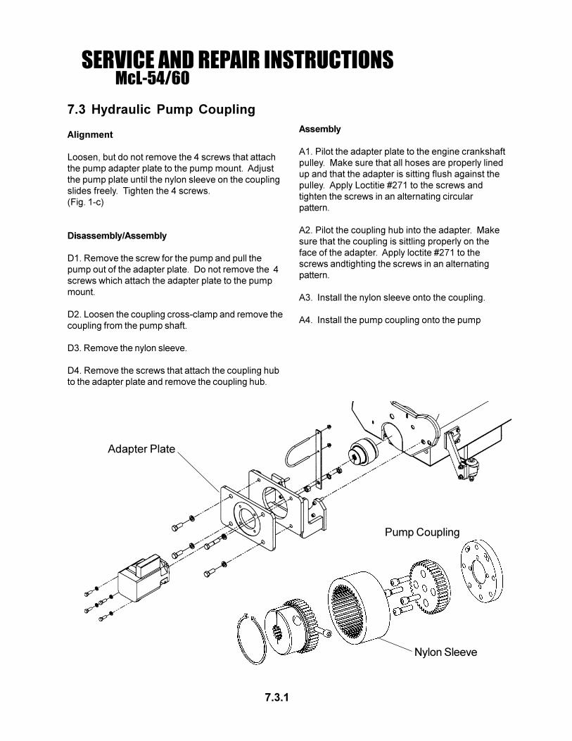
Pump Coupling
Nylon Sleeve
Adapter Plate
Assembly
A1. Pilot the adapter plate to the engine crankshaft
pulley. Make sure that all hoses are properly lined
up and that the adapter is sitting flush against the
pulley. Apply Loctitie #271 to the screws and
tighten the screws in an alternating circular
pattern.
A2. Pilot the coupling hub into the adapter. Make
sure that the coupling is sittling properly on the
face of the adapter. Apply loctite #271 to the
screws andtighting the screws in an alternating
pattern.
A3. Install the nylon sleeve onto the coupling.
A4. Install the pump coupling onto the pump
SERVICE AND REPAIR INSTRUCTIONSMcL-54/60
7.3 Hydraulic Pump Coupling
Alignment
Loosen, but do not remove the 4 screws that attach
the pump adapter plate to the pump mount. Adjust
the pump plate until the nylon sleeve on the coupling
slides freely. Tighten the 4 screws.
(Fig. 1-c)
Disassembly/Assembly
D1. Remove the screw for the pump and pull the
pump out of the adapter plate. Do not remove the 4
screws which attach the adapter plate to the pump
mount.
D2. Loosen the coupling cross-clamp and remove the
coupling from the pump shaft.
D3. Remove the nylon sleeve.
D4. Remove the screws that attach the coupling hub
to the adapter plate and remove the coupling hub.
7.4 DOG PLATE
Dog Pin Indicators - The dog pin indicator lights should come on when the dog pins are retracted and go
off when the dog pins are fully extended. Adjust the switches so the lights give an accurate indication of
the dog pin position. Sometimes the dog pin may be in a bind and may not be able to extend fully. Check
that the dog pins are working freely before making any adjustments. Make sure that the dog pin valve is
open enough (5-6 turns) for the pins to move freely.
Dog Pin Indicator Switch Adjustment
1. Extend the dog pins.
2. Remove the top plate on the dog plate cover box.
2. Turn the ignition switch to the “ON” position and note dog pin positions and dog pin indicator lights.
3. The switch brackets allow for adjustment forward and backward, and side to side. Loosen, but do not
remove the screws which will allow movement in the required direction for proper switch placement.
Note: The switch should be positioned with “DIM A” = 1/4”-3/8” air gap between the switch arm and the
hydraulic dog plate cylinder. Refer to the illustration above.
4. Tighten the screws and test the operation by repeatedly extending and retracting the dog pins. Repeat
these steps if further adjustments are necessary.
Dog Pin Indicator DetailSome items not shown for clarity.
SERVICE AND REPAIR INSTRUCTIONSMcL-54/60
7.4.1
Dog Plate Cylinder Replacement
D1. Open the dog pin valve completely.
D2. Remove the top plate of dog plate box.
D3. Disconnect and cap the hydraulic hose at the cylinder swivel fitting.
D4. Remove the two screws that attach the cylinder to the dog pins. The dog pins are spring loaded, so
there will be pressure on the screws when they are removed. Note: Be careful not to damage machine
components still in place, wires, switches, etc.
D5. It is recommended that the dog plate be thoroughly cleaned whenever the dog plate cylinder is
removed.
D6. Remove the dog pins and dog pin springs. Clean the dog pins and remove any rust or corrosion on
the pins. Clean any mud or dirt out of the springs. Replace springs if necessary. Clean the dog plate
housing. Make sure the dog pins can slide freely in and out by hand, before reassembling.
A1. The dog pin has a top and a bottom. The top of the dog pin is determined by the depth of the set
screw in the tapped hole. The top of the dog pin has a set screw depth of ~ 5/16”. If this dimension is not
correct, adjust the set screw. Remove the set screw and clean off any residual thread lock. Clean the
tapped hole in the dog pin. Apply Loctite #243 to the set screw and insert it into the dog pin to the proper
depth. Allow the thread lock to cure before reassembling.
7.4.2
SERVICE AND REPAIR INSTRUCTIONSMcL-54/60
Dog Plate Adjustable Valve
A2. Insert the dog pin springs into the dog plate. Make sure the springs slide over the center pin and areseated on the stop in the center of the housing.
A3. After the dog plate and pins have been cleaned, apply a thin film of oil to the pins and insert them into thedog plate. Do not use grease or heavy oils. These heavier lubricants tend to attract dirt more than lighteroils.
A4. Press the dog pins into the housing until the tapped holes in the dog pins are accessable in the slots inthe top plate.
A5. Put the cylinder screws through the cylinder end lugs and thread the screws into the dog pins.Tighten the screws until they bottom out on the set screws in the dog pins. Once tight, there should be asmall gap between the base of the cylinder and the dog plate. The gap keeps the cylinder from pulling thedog pins against the top of the dog plate. Note: The cylinder must be positioned properly to match up withthe dog pin indicator switches.
A6. Connect the hose to the dog plate cylinder swivel fitting.
A7. Operate machine and check for leaks.
A8. Replace the top plate.
Dog Plate Cylinder Seal Kit Replacement
D1. Remove cylinder as described in the above section.
D2. Remove the swivel fitting and unscrew the threaded cap.
NOTE: FLUID UNDER PRESSURE. THERE MAY BE REMAINING HYDRAULIC FUILD IN THE CYLINDER.
EXTENDING OR RETRACTING THE CYLINDER CAN FORCE FLUID OUT OF THE CYLINDER. FLUID
UNDER PRESSURE CAN CAUSE SERIOUS INJURY.
D3. Pull the rod assembly out of the barrrel.
D4. Remove the piston from the end of the rod assembly.
D5. Remove the threaded cap from the rod assembly.
D6 Remove and discard all seals, o-rings, back-up washers and wipers. Visually note the placement and
orientation of all seals before removal.
A1. Clean all components with brake cleaner and let dry.
A2. Refer to the Dog Plate Cylinder Components section of this manual for proper seal placement and
orientation. Lube all seals and wipers with a thin coat of oil before assembly.
A3. Install the threaded cap onto the rod assembly, note proper orientation.
A4. Install the piston onto the rod assembly.
A5. Insert the rod assemlby into the barrel.
A6. Tighten the threaded cap.
A7. Refer to Dog Plate Cylinder Replacement instructions for assemlby procedure.
7.4.3
SERVICE AND REPAIR INSTRUCTIONSMcL-54/60
THRUST CYLINDER
Removal:
D1. Remove the carriage from the jacking station.
D2. Disconnect and cap the hydraulic hoses and cylinder ports.
D3. Disconnect the hydraulic and electrical connections at the dog plate.
D4. Remove the 3 cylinder pins in the dog plate and slide the dog plate away from the cylinders.
D5. Remove the cylinder from the jacking station. Note: Be careful not to damage machine componentsalready in place.
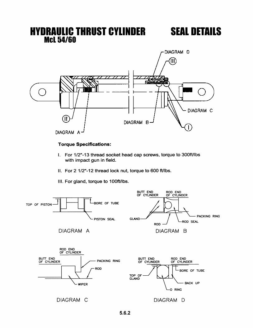
Thrust Cylinder Seal Kit Replacement:
D1. Remove the rod clevis.
D2. Remove the rod-end base plate.
D3. Unscrew the rod end cap.
D4. Pull the rod assembly out of the barrel.
D5. Remove the piston from the end of the rod assembly.
D6. Remove and discard all seal and wipers. Visually note the placement and orientation of all sealsbefore removal.
A1. Clean all components with brake cleaner and let dry.
A2. Refer to the Thrust Cylinder Components section of this manual for proper seal placement and orienta-tion and torque requirements for fasteners. Lube all seals with a light coat of oil before assembly.
A3. Install the piston on the rod assembly and torque the retaining nut to the proper specifications.
A4. Insert the rod assembly into the barrel.
A5. Install the rod end cap and torque to the proper specifications.
A6. Install the rod end plate and torque screws to the proper specifications.
A7. Position the cylinder in the jacking station and reinsert the cylinder pin.
A8. Position the dog plate on the cylinders and insert the dog plate cylinder pins.
A9. Connect the hoses.
A10. Connect the hydraulic and electrical connections at the dog plate.
A11. Install the carriage.
A12. Operate the machine and check for leaks.
7.5.1
SERVICE AND REPAIR INSTRUCTIONSMcL-54/60
7.6.1
SERVICE AND REPAIR INSTRUCTIONSMcL-54/60
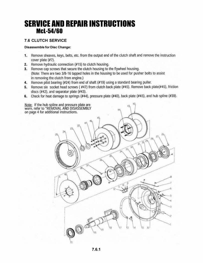
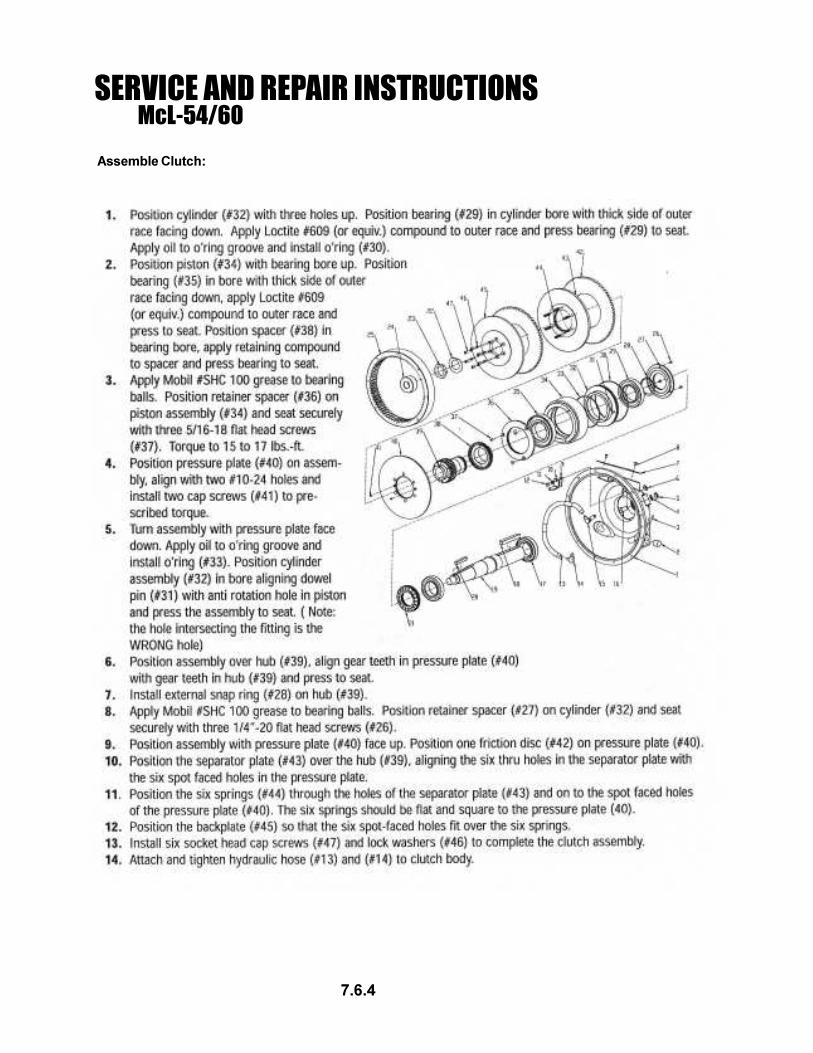
7.6 CLUTCH SERVICE
Disassemble for Disc Change:
7.6.2
SERVICE AND REPAIR INSTRUCTIONSMcL-54/60
Assemble for Disc Change:
7.6.3
SERVICE AND REPAIR INSTRUCTIONSMcL-54/60
Disassemble Clutch:
7.6.4
SERVICE AND REPAIR INSTRUCTIONSMcL-54/60
Assemble Clutch:
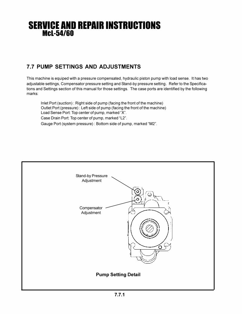
7.7 PUMP SETTINGS AND ADJUSTMENTS
This machine is equiped with a pressure compensated, hydraulic piston pump with load sense. It has two
adjustable settings, Compensator pressure setting and Stand-by pressure setting. Refer to the Specifica-
tions and Settings section of this manual for those settings. The case ports are identified by the following
marks:
Inlet Port (suction) : Right side of pump (facing the front of the machine)
Outlet Port (pressure) : Left side of pump (facing the front of the machine)
Load Sense Port: Top center of pump, marked “X”.
Case Drain Port: Top center of pump, marked “L2”.
Gauge Port (system pressure) : Bottom side of pump, marked “M2”.