52
Components for on-board application Contactors DC High Speed Circuit Breakers Disconnectors Resistors Communication and Control Systems Metering Systems Fans
C o m p o n e n t s f o r o n - b o a r d a p p l i c a t i o n
ContactorsDC High Speed Circuit Breakers DisconnectorsResistorsCommunication and Control Systems Metering SystemsFans
2
Applications
Switches and Disconnectors for traction and auxiliary converter
System Configuration Switches
High Speed Circuit Breaker (roof or under frame mounted)
Cab Heating Contactors
Brake Resistor
Control Resistors
Metering Transducers
Traction Motor Blowers
Brake Resistor Blower
Converter Cooling Blower
Integrated Functional Units
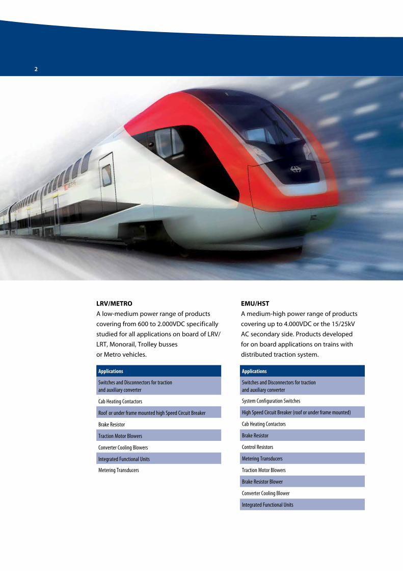
EMU/HST
A medium-high power range of products
covering up to 4.000VDC or the 15/25kV
AC secondary side. Products developed
for on board applications on trains with
distributed traction system.
Applications
Switches and Disconnectors for traction and auxiliary converter
Cab Heating Contactors
Roof or under frame mounted high Speed Circuit Breaker
Brake Resistor
Traction Motor Blowers
Converter Cooling Blowers
Integrated Functional Units
LRV/METRO
A low-medium power range of products
covering from 600 to 2.000VDC specifically
studied for all applications on board of LRV/
LRT, Monorail, Trolley busses
or Metro vehicles.
Metering Transducers
3
C o m p o n e n t s f o r o n - b o a r d a p p l i c a t i o n
Products
ContactorsDisconnectors
DC High Speed Circuit Breakers
Braking ResistorsResistors for Traction Control
High Voltage Transducers
Fans
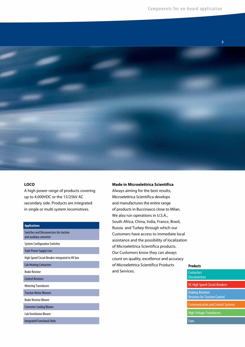
LOCO
A high power range of products covering
up to 4.000VDC or the 15/25kV AC
secondary side. Products are integrated
in single or multi system locomotives.
Made in Microelettrica Scientifica
Always aiming for the best results,
Microelettrica Scientifica develops
and manufactures the entire range
of products in Buccinasco close to Milan.
We also run operations in U.S.A.,
South Africa, China, India, France, Brasil,
Russia and Turkey through which our
Customers have access to immediate local
assistance and the possibility of localization
of Microelettrica Scientifica products.
Our Customers know they can always
count on quality, excellence and accuracy
of Microelettrica Scientifica Products
and Services.
Applications
Switches and Disconnectors for traction and auxiliary converter
Train Power Supply Line
High Speed Circuit Breaker integrated in HV box
Cab Heating Contactors
Brake Resistor
Control Resistors
Metering Transducers
Traction Motor Blowers
Brake Resistor Blower
Cab Ventilation Blower
Integrated Functional Units
Converter Cooling Blower
System Configuration Switches
Communication and Control Systems
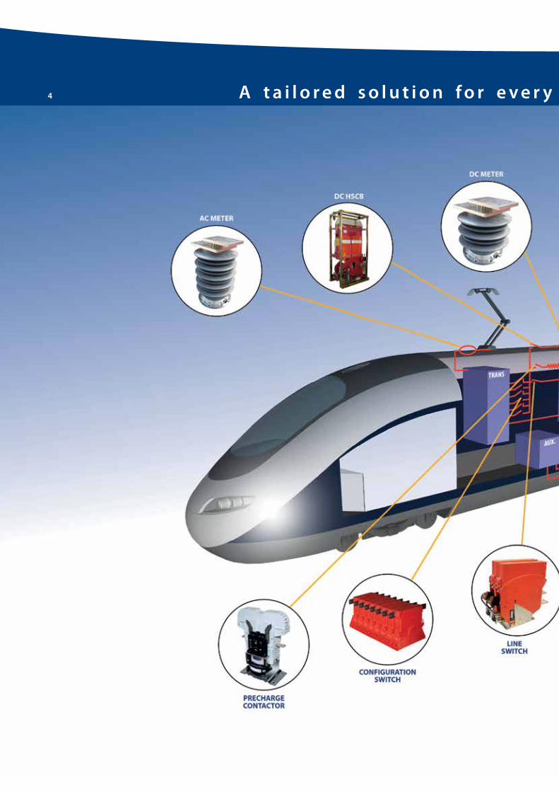
4 A t a i l o r e d s o l u t i o n f o r e v e r y t r a c t i o n c o m p o n e n t n e e d

5
C o m p o n e n t s f o r o n - b o a r d a p p l i c a t i o n
A t a i l o r e d s o l u t i o n f o r e v e r y t r a c t i o n c o m p o n e n t n e e d

6 C o n t a c t o r s
Applications
Line contactor
Power or auxiliary converter input
Filter pre-charging
Traction motors on-load disconnection
Electromagnetic brakes
Heating/Air conditioning systems
Microelettrica Scientifica contactors for railway applications are designed to be used on
electrical equipment in presence of the most severe conditions, such as shocks and vibrations,
which occur on on-board traction vehicles.
The LTHS Line displays a traditional design which enables them to withstand the highest
current ratings in harsh working conditions.
To accomplish most of the possible applications, all the LTHS contactors can be manufactured
in single or multipolar form and, upon request, allow a very high degree of customization.
Versions with normally open or normally closed poles are manufactured, and mechanical
latching can be supplied. In order to work efficiently both with high and low currents, the
contactors are equipped with indirect blow out circuit. This arc-extinguishing technology
allows to work indifferently in AC as well as DC.
The DC control coil operates without economy resistor within a wide working range. A
“varistor” cuts off the peak voltage when the coil is de-energized.
More than 20000 LTHS contactors are delivered every year for the most demanding projects
and applications worldwide.
Auxiliary contact blocks type SL11
• Up to 4 blocks normally mounted on LTHS contactors
• 1 NO + 1 NC or 2 NO block versions available
• Made in self-extinguishing Latamid polyamide that guarantees high electrical and mechanical
• Performances as well as very low temperature resistance
• Double interrupting, self-cleaning, solid silver contacts
• On request special execution with gold plate contacts
• The most experienced extra heavy duty line
• Designed for on-board applications according to IEC 60077
• Ratings up to 2000 VDC/AC and up to 1600 A/pole application
• Direct or indirect arc blow-out systems available according specific application requirements
• Multi-pole combination up to 4 NO or NC poles
• Very high level of customization available
LTHS line
HD
w
LTHS 60
General Characteristics

C o m p o n e n t s f o r o n - b o a r d a p p l i c a t i o n
7
LTHS 125
LTHS 320/380
LTHS 400
LTHS 1500/1700
LTHS 650/800/1250
Type Umax [VAC/DC] Ith [A] W [mm] H [mm] D1/D2 [mm]
(1/2 poles)
LTHS 60 1000 80 143 197 72/93
LTHS 125 1000 150 185 276 86/114
LTHS 320 2000 350 220.5 300.5 86/114
LTHS 380 2000 380 220.5 300.5 86/114
LTHS 400 2000 500 329 423 115.5/202
LTHS 650/800 2000 700/920 335 438(D1)/441(D2) 119/206.5
LTHS 1250 2000 1300 350 473(D1)/476(D2) 127.2/206.5
LTHS 1500 2000 1350 350 533.5(D1)/536.5(D2) 111/215
LTHS 1700 2000 1600 350 533.5(D1)/536.5(D2) 127/235
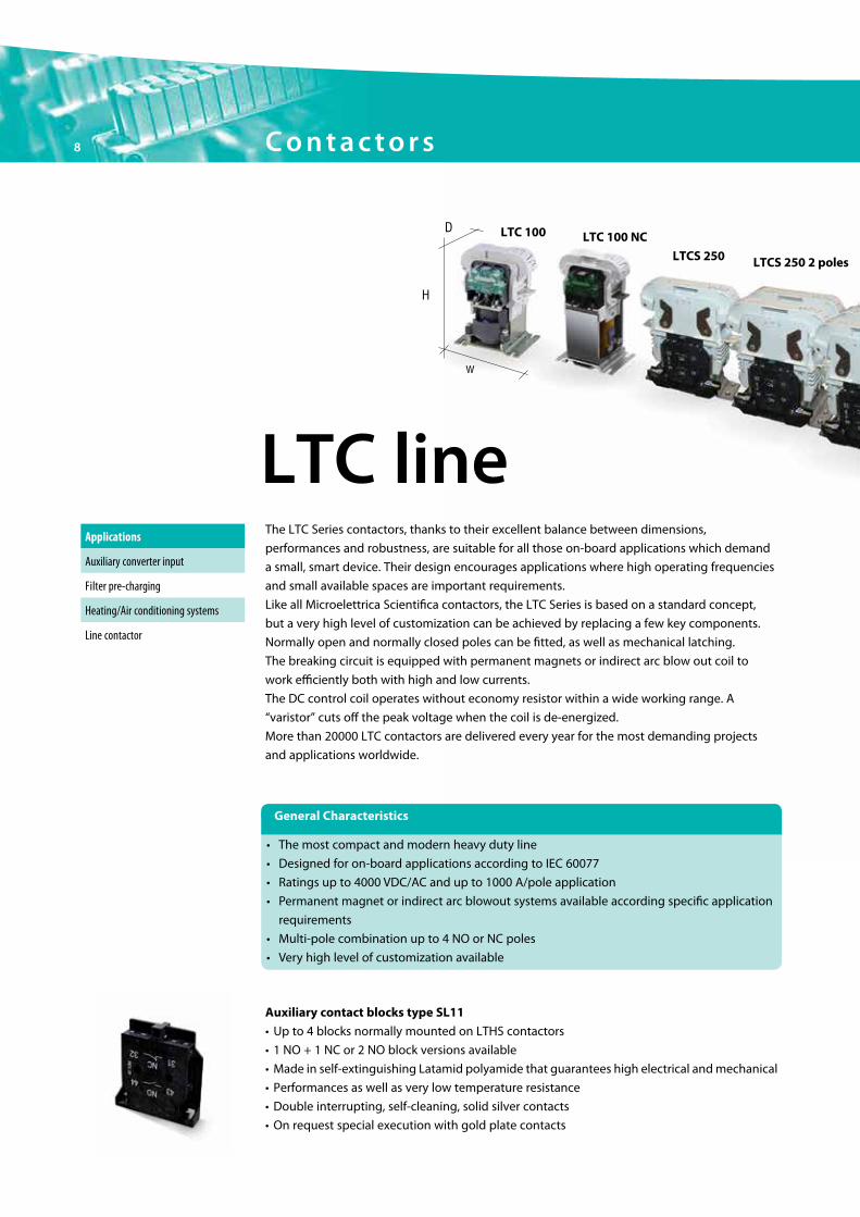
LTC 100 LTC 100 NC
LTCS 250 LTCS 250 2 poles
LTC lineApplications
Auxiliary converter input
Filter pre-charging
Heating/Air conditioning systems
Line contactor
The LTC Series contactors, thanks to their excellent balance between dimensions,
performances and robustness, are suitable for all those on-board applications which demand
a small, smart device. Their design encourages applications where high operating frequencies
and small available spaces are important requirements.
Like all Microelettrica Scientifica contactors, the LTC Series is based on a standard concept,
but a very high level of customization can be achieved by replacing a few key components.
Normally open and normally closed poles can be fitted, as well as mechanical latching.
The breaking circuit is equipped with permanent magnets or indirect arc blow out coil to
work efficiently both with high and low currents.
The DC control coil operates without economy resistor within a wide working range. A
“varistor” cuts off the peak voltage when the coil is de-energized.
More than 20000 LTC contactors are delivered every year for the most demanding projects
and applications worldwide.
H
D
w
• The modern and compact heavy duty line, up to 4000VDC/AC application, up to 1000A/pole
• On-board and stationary applications
• 1-2-3 and 4 pole configuration available, NO and NC poles, permanent magnets
or indirect arc blow outs
• Flexible control and auxiliary contacts options, customization available
General Characteristics
8 C o n t a c t o r s
• The most compact and modern heavy duty line
• Designed for on-board applications according to IEC 60077
• Ratings up to 4000 VDC/AC and up to 1000 A/pole application
• Permanent magnet or indirect arc blowout systems available according specific application
requirements
• Multi-pole combination up to 4 NO or NC poles
• Very high level of customization available
Auxiliary contact blocks type SL11
• Up to 4 blocks normally mounted on LTHS contactors
• 1 NO + 1 NC or 2 NO block versions available
• Made in self-extinguishing Latamid polyamide that guarantees high electrical and mechanical
• Performances as well as very low temperature resistance
• Double interrupting, self-cleaning, solid silver contacts
• On request special execution with gold plate contacts

LTCS 250 2 poles
LTC 250 NC
LTCH 250
LTCH 60
LTCH 1000
LTCS 250 3 poles
Type Umax [VAC/DC] Ith [A] W [mm] H [mm] D [mm]
LTC 100 1000 100 106 127.5 63
LTC 100 2 poles 1000 100/200 120 127 93
LTC 100 NC 1000 100 106 155 60
LTCS 250/300 2000 250 140 156.5 86
LTCS 250/300 2 poles 2000 250/500 140 156.5 109.2
LTCS 250/300 3 poles 2000 250 140 156.5 165.5
LTC 250/300 NC 2000 250 140 196 78
LTCH 250 2000 250 154 176 86
LTCH 60 4000 60 168 221 88
LTCH 60 2 poles 4000 60/120 168 221 125
LTCH 1000 2000 1000 385 300 93
9
C o m p o n e n t s f o r o n - b o a r d a p p l i c a t i o n

10 C o n t a c t o r s
The Microelettrica Scientifica LTHH/LTE/LTP Lines for electric traction are supplied to railways
and underground systems throughout the world.
Where high voltage ratings are required, the LTHH Series contactors are the right solution.
The creepage and clearance distances are widely dimensioned for safe application in polluted
environments. Their narrow outline is especially conceived for applications where space is a
critical issue - as more and more often happens on railway vehicles.
To meet all possible applications, they are available both with electric (LTHH/LTE) and
pneumatic (LTP) control, and poles can be manufactured in normally open or normally closed
configurations.
The direct or indirect blow out circuit makes the LTHH contactors suitable to work both with
high and low currents.
The DC control coil operates without economy resistor within a wide working range. More
than 10000 LTHH contactors are delivered every year for the most demanding projects and
applications worldwide.
Applications
Auxiliary converter input
Filter pre-charging
Capacitor discharging
Heating/Air conditioning systems
Line contactor
Train supply line
Resistors based traction systems, for starting and braking of electric motors
Auxiliary Contact Blocks Type SJ11
• Normally mounted on LTHH contactors
• 1 NO + 1 NC or 2 NO block versions available
• Execution in Makrolon, self-extinguishing and transparent polycarbonate
• Double interrupting, self-cleaning, solid silver, snap action contacts
• On request special execution with gold plated contacts
LTHH/LTE/LTP line
LTHH 100LTHH 40
H
D
w
• The higher voltage single pole heavy duty line, up to 4000VDC/AC application, up to 1350A/pole
• On-board and stationary applications
• Multipole assemblies, NO and NC poles, indirect arc blow out
• Flexible control and auxiliary contacts options, high unit customization available
General Characteristics
• The highest voltage single pole heavy duty line
• Designed for on-board applications according to IEC 60077
• Ratings up to 4000 VDC/AC and up to 1350 A/pole application
• Direct or indirect arc blow-out systems available according specific application requirements
• Multi-pole assemblies, NO or NC poles
• Very high level of customization available

11
C o m p o n e n t s f o r o n - b o a r d a p p l i c a t i o n
LTHH 250/400
LTP 2-400/600
LTP 4-400/600
LTP 4-2000
Type Umax [VAC/DC] Ith [A] W [mm] H [mm] D1/D2 [mm]
(1/2 poles)
LTHH 40 2000 60 200(D1)/244(D2) 162.5(D1)/174.5(D2) 48/106
LTHH 100 4000 120 377(D1)/410(D2) 274(D1)/279(D2) 60/130
LTHH 250 4000 300 380.5(D1)/424(D2) 297(D1)/302(P2) 70/160
LTHH 400 4000 400 380.5(D1)/424(D2) 297(D1)/302(P2) 70/160
LTE 2-400 2000 900 428 367 80/-
LTE 2-600 2000 900 430 370(D1)/365(D2) 80/220
LTP 2-400 2000 900 402 367 80/-
LTP 2-600 2000 900 402 370 80/-
LTE 4-400 4000 900 429.4(D1)/379.3(D2) 394 85/175
LTE 4-600 4000 900 429.4 423 85/-
LTP 4-400 4000 900 402 394 85/-
LTP 4-600 4000 900 402 423 85/-
LTE 4-2000 4000 1350 501 473 119/-
LTP 4-2000 4000 1350 501 473 151.5/-

12
A key of Microelettrica Scientifica success is the ability to provide specific solutions to meet
customers’ requirements. One of these are IFUs: different Microelettrica Scientifica contactors
and disconnectors are supplied already assembled on a structure. A several solutions have
been supplied also including charging and discharging resistors on the same frame. In this
way customers do not have to worry of installing several components on a vehicle: it’s just
a matter of inserting the whole assembly in its own cubicle and tightening some screws.
For example, all the traction circuit switchgears can be part of just one IFU. Such a solution
helps also in case of maintenance: a IFU is removed from the train in a short time and
is replaced with another assembly, to speed up processes. Then, the removed IFU
can be checked and revamped in the workshop, with no concerns of time and space.
Integrated Functional Units
C o n t a c t o r s

13
C o m p o n e n t s f o r o n - b o a r d a p p l i c a t i o n
4 QS
4 QS
15kV 16.6Hz/25kV 50Hz
Pre-charging contactor
Transformer tapping change over disconnector
Main power contactor
Main power and pre-charging contactors+ change over disconnector
Line and pre-charging contactor+ pre-charging resistor

14
New modular integrated system LPRC 1000 consisting of LTCH 1000 line contactor associated
with LTCS 150 pre-charge contactor and pre-charge resistor.
LPRC line
Technical advantages
• The electrical connections are integrated so that the terminals are limited to “In” and “Out” only
• Excellent performances with reduced weight and volume
• Quick installation: common interface for HV and for LV
• Quick maintenance: low time to substitute all the system or the single components
• The LTCH 1000 line contactor has a dedicated base-plate and works up to 2kV – 1000A
• The new LTCS 150 pre-charge contactor is available in 2 poles series connected
configuration for applications up to 1kV or up to 2kV. Its overall dimensions are limited as
it is enclosed in the volume of the LTCH 1000 for the most part
• The pre-charge resistor, integrated in the base, has different resistance values depending
on the application
General characteristics
C o n t a c t o r s

15
C o m p o n e n t s f o r o n - b o a r d a p p l i c a t i o n
LTCS150 2NO
Pre-Charge Resistor
LTCH 1000
Type Umax [VAC/DC] Ith [A] Resistance [Ω]
LTCH 1000 2000 1000 -
LTCS 150 2NO 2000 150 -
Pre-Charge Resistor - - 10 ÷ 100
Dimensions
414
356
160
LTCS150 2NO Pre-Charge Resistor
LTCH 1000
16 D C H i g h S p e e d C i r c u i t B r e a k e r s
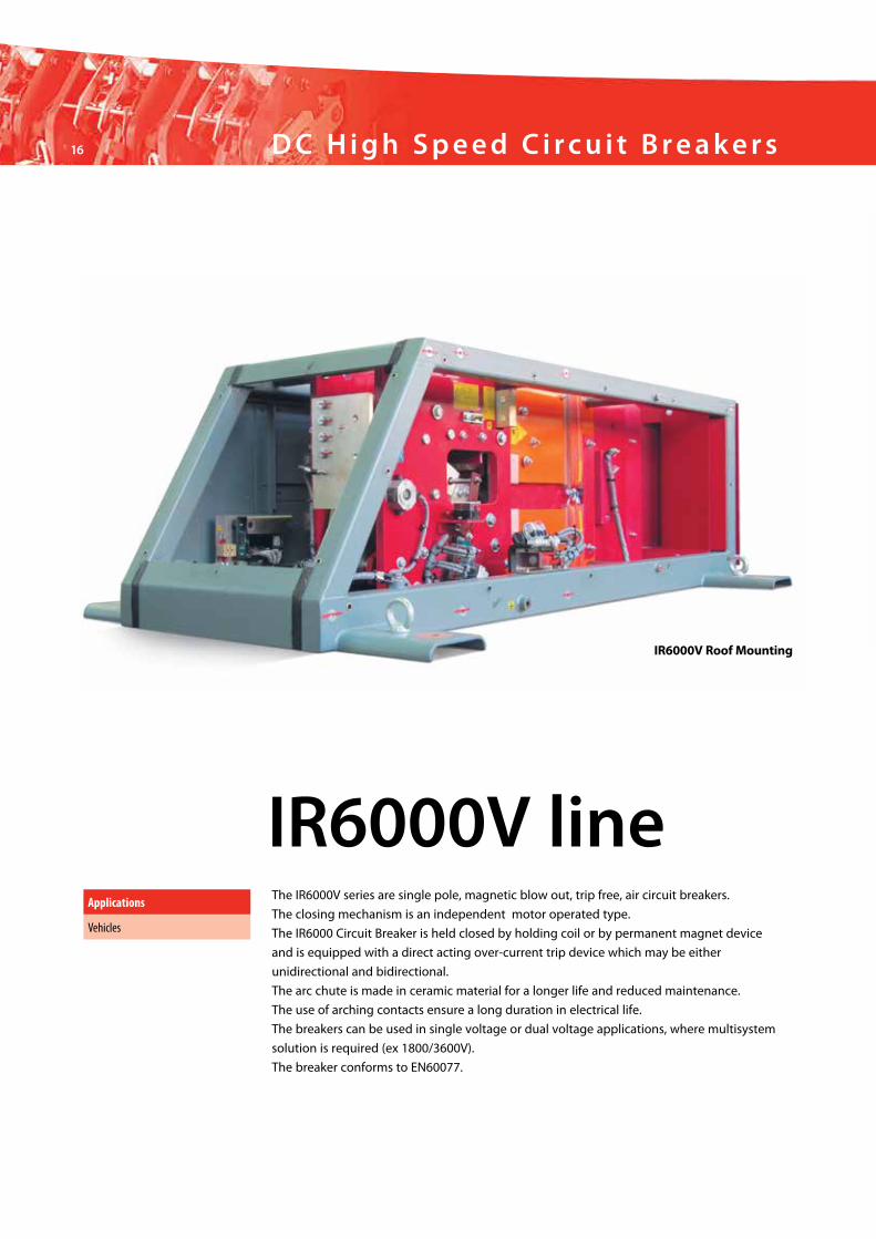
The IR6000V series are single pole, magnetic blow out, trip free, air circuit breakers.
The closing mechanism is an independent motor operated type.
The IR6000 Circuit Breaker is held closed by holding coil or by permanent magnet device
and is equipped with a direct acting over-current trip device which may be either
unidirectional and bidirectional.
The arc chute is made in ceramic material for a longer life and reduced maintenance.
The use of arching contacts ensure a long duration in electrical life.
The breakers can be used in single voltage or dual voltage applications, where multisystem
solution is required (ex 1800/3600V).
The breaker conforms to EN60077.
Applications
Vehicles
IR6000V line
IR6000V Roof Mounting

17
C o m p o n e n t s f o r o n - b o a r d a p p l i c a t i o n
Type Umax [V] I [A] W [mm] H [mm] L [mm]
IR6000 Vertical up to 3600 4000 420 1250 650
IR6000 Horizontal up to 3600 2500 470 680 1200
IR6000 Roof up to 3600 2500 560 525 1600
IR6000V Horizontal
IR6000V Vertical
650
1250
M12106
56
Earthing point
424
464
Overall Dimensions: mm
(4) Ø 17
800 120
610
470
70
45
560
1200
680

18 D C H i g h S p e e d C i r c u i t B r e a k e r s
IR3000V lineThe IR3000V series are single pole, magnetic blow out, trip free, air circuit breakers.
The closing mechanism is an independent motor operated type.
The IR3000V Circuit Breaker is held closed by holding coil or by permanent magnet device
and is equipped with a direct acting over-current trip device which may be either
unidirectional and bidirectional.
The arc chute is made in ceramic material for a longer life and reduced maintenance.
The use of arching contacts ensure a long duration in electrical life.
The IR3000V is available in a IP45 plastic box or IP55 metallic box.
The breaker conforms to EN60077.
Applications
On the roof under frame
On board
IR3000V @ 900 Vdc IR3000V @ 1800 Vdc

19
C o m p o n e n t s f o r o n - b o a r d a p p l i c a t i o n
Type [Vdc] Umax [V] I [A] W [mm] H [mm] L [mm]
IR3015V @ 900 900 1500 220 395 530
IR3015V @1800 1800 1500 220 478 530
IR3030V @ 900 900 3000 220 395 530
IR3030V @1800 1800 3000 220 478 530
546,50 250,50
H
20 D i s c o n n e c t o r s
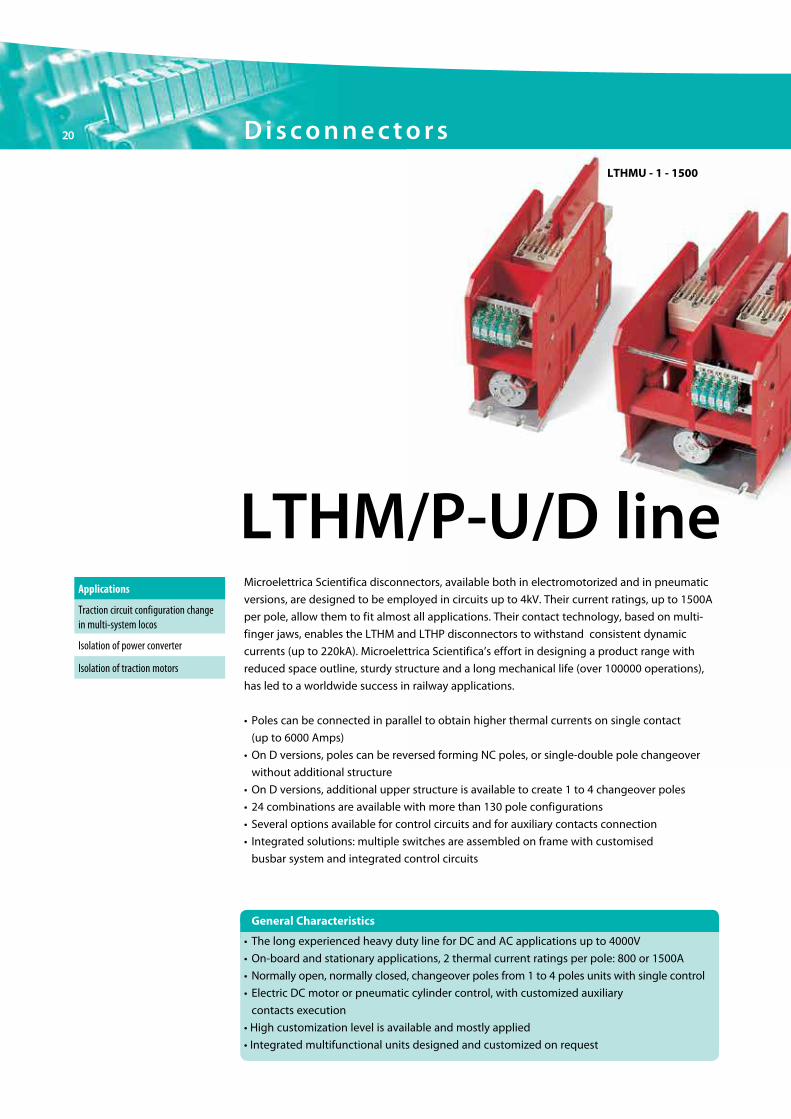
Microelettrica Scientifica disconnectors, available both in electromotorized and in pneumatic
versions, are designed to be employed in circuits up to 4kV. Their current ratings, up to 1500A
per pole, allow them to fit almost all applications. Their contact technology, based on multi-
finger jaws, enables the LTHM and LTHP disconnectors to withstand consistent dynamic
currents (up to 220kA). Microelettrica Scientifica’s effort in designing a product range with
reduced space outline, sturdy structure and a long mechanical life (over 100000 operations),
has led to a worldwide success in railway applications.
• Poles can be connected in parallel to obtain higher thermal currents on single contact
(up to 6000 Amps)
• On D versions, poles can be reversed forming NC poles, or single-double pole changeover
without additional structure
• On D versions, additional upper structure is available to create 1 to 4 changeover poles
• 24 combinations are available with more than 130 pole configurations
• Several options available for control circuits and for auxiliary contacts connection
• Integrated solutions: multiple switches are assembled on frame with customised
busbar system and integrated control circuits
LTHM/P-U/D lineApplications
Isolation of traction motors
Traction circuit configuration change in multi-system locos
Isolation of power converter
LTHMU - 1 - 1500
• The long experienced heavy duty line for DC and AC applications up to 4000V
• On-board and stationary applications, 2 thermal current ratings per pole: 800 or 1500A
• Normally open, normally closed, changeover poles from 1 to 4 poles units with single control
• Electric DC motor or pneumatic cylinder control, with customized auxiliary
contacts execution
• High customization level is available and mostly applied
• Integrated multifunctional units designed and customized on request
General Characteristics

21
C o m p o n e n t s f o r o n - b o a r d a p p l i c a t i o n
Auxiliary Connections
• To meet all customer requirements, special connections and cabling can be supplied both
on the high voltage and on the low voltage circuits. On the HV side, poles can be connected
in series or parallel. Terminals can be shaped according to customers’ requirements
• LV circuits can be cabled to perform different logical functions. Any kind of connector
available in commerce can be fitted to these circuits
• M/P: Electromotorized (M) or Pneumatic (P) bistable control • U/D: Power terminals on same side (U) or on opposite side (D) • 1/2/3/4: Number of poles• 800/1500: Thermal current of each pole (in Amps)
LTH P D 1 800LTH M U 1 1500 LTH P D 1 1500LTH M U 2 800 LTH P D 2 800
LTH M U 2 1500 LTH P D 2 1500LTH P D 3 800LTH P D 3 1500LTH P D 4 800
LTH P D 4 1500
LTHMU - 2 - 1500
LTHPD - 2 - 1500
LTHPD - 3 - 800
LTHPD - 4 - 800 CO
LTH M U 1 800 LTH P U 1 800LTH P U 1 1500LTH P U 2 800
LTH P U 2 1500
LTH M D 1 800LTH M D 1 1500LTH M D 2 800LTH M D 2 1500LTH M D 3 800LTH M D 3 1500LTH M D 4 800
LTH M D 4 1500

22 D i s c o n n e c t o r s
Modular multipole-multiposition off-load disconnectors.
The disconnectors are configurable assembling side by side poles, every one completely
independent and controlled by a motor.
The modular structure allows easy maintenance through independent replaceability of every
single pole. Feedbacks may be managed, on demand, through a low voltage connector
installed on every pole.
Reference standard IEC 60077-2.
LTMP lineApplications
Isolation of traction motors
Traction circuit configuration change in multi-system locos
Isolation of power converter

C o m p o n e n t s f o r o n - b o a r d a p p l i c a t i o n
23
Technical Data
Pole Configuration
NO Pole CO Pole
Overall dimensions (mm)
1775 145.25
Ø 13 50
352
50
10
100 100 52
50
20
45
100 100 52
55
Ø 935
015
348
4040
458
15
Main Features of each Pole:
• 2 versions: 1000 or 2000A thermal current
• 3 configurations: NO or NO+NC or CO
• Fully modular construction
• Electric motor actuated
Rated Max Voltage (Umax) 4000VDC/AC
Rated Operational Current (Ie) at 75°C Up to 2000A
Auxiliary Contacts (typeSAIA-BURGESS) 2 CO per pole
NO-NC Pole

24 D i s c o n n e c t o r s
Microelettrica Scientifica disconnector designed for circuit up to 4kV and available with
electric motor control (24, 36, 72 and 110VDC).
Its compact dimensions make it particularly suitable for application up to 300A where 3 or 4
poles (1NO+1NC or CO) are required to be fitted in little space.
As for the largest part of Microelettrica switches LTRM line may be easily personalized in order
to match with customers specifications. This, combined with easy on-board maintenance,
high performances and reliability are the most relevant characteristics of this device.
LTRM lineApplications
Reverser
Traction system configuration
Isolation of power converter
H
D
W

C o m p o n e n t s f o r o n - b o a r d a p p l i c a t i o n
25
Auxiliary connection
LV circuit can be cabled according to customer requirements to perform
different logic functions:
• direct control through auxiliary contacts
• control made by mean of one relay
• control made by mean of two relays
Any kind of connector available in commerce may be used on request.
Reference Standard
• EN60077-1
• En60077-2
• EN61373
• EN50124-1
• TS45545-2
Type Umax [VDC/AC] Ith [A] W [mm] H [mm] Dmax [mm]
LTRM 3 poles 2000 300 193 341 331
LTRM 3 poles 4000 300 300 341 331
LTRM 4 poles 2000 300 252 341 388
LTRM 4 poles 4000 300 300 341 388

26
CompactAluminiumResistorsThese products are characterized by compact and modern design that ensures combination
of lightness, low inductance and great energy absorption capacity.
Depending on application, there is the possibility to base either on an aluminium housing or
on an aluminium profile housing with integrated cooling fans.
By connecting multiple compact resistors in series, resistor units with capacities of between
50 W and 10 kW can be reached. Accordingly, protection classes up to
IP 66 are guaranteed.
Resistance material support: moulded ceramic base
Resistance wire: NiCr-alloy special heat sink casing
Degree of protection: IP64 up to IP66
Applications
Braking and chopper resistors for variable speed drives
Load and testing resistor
Integration in mounting beneath or beside frequency inverter

27
C o m p o n e n t s f o r o n - b o a r d a p p l i c a t i o n
Wire WoundResistors
Applications The best feature of wire wound resistors and the last application for wire wound technology,
are their compact and modular design, joined to high energy absorption capacity.
Optimization on frame combined with electrical insulation guarantees low inductivity and
high insulation voltage. All coupled with great ability of the wire wound resistor to maintain
high absorption even if resistor wire heats up. These products are available in protection
classes from IP00 to IP 23.
The ability to use them as thermal switches for thermal monitoring and overcurrent relays for
controlling overload events opens them to a wide range of applications.
Resistance material support: grooved ceramic insulators fixed on both longitudinal sides of
a metal or temperature-resistant insulating material frame
Resistance wire: CuNi 44 or NiCr alloy
Taps (tapping eyes): on request
Degree of protection: IP00 - IP23 possible
Braking and chopper resistors in variable-speed drivers
Frequency inverters
Load and testing resistorsCircuit resistors

28
Stripe ElementResistorStripe element technology is spearhead of our products and it is mainly used for braking
resistors. These resistors are projected and manufactured directly according with customer
requirements and can reach megawatt – range capacities.
The great capacity of this application is the possibility to define each parameter of stripe
element, defining dimension and also stainless steel alloy that better satisfy the customer
requirements, ensuring high energy absorbance capacities, rapid heat dissipation and control
on ohmic range. For this reason braking resistor are used to transform kinetic energy of the
vehicle into heat. Depending on the customer’s requirements, cooling can be implemented
by convection or forced by specially – sized fan.
Braking Resistors are usually installed:
• On the roof of a vehicle, where hot exhaust air is released upwards
• Under frame, where the hot air released is exhausted sideways when the vehicle
is in motion or using a blower
• Inside the vehicle, where the resistors are usually forced air cooled, where fresh
air is taken from the bottom of the vehicle and hot air is expelled from the top

29
C o m p o n e n t s f o r o n - b o a r d a p p l i c a t i o n
Applications
Rail Vehicles
Resistor elements are assembled in banks by means of strong rods and ceramic spacers.
Segments of resistor banks are mounted in a strong support frame of AISI304 stainless steel.
Stainless steel is also used for bolts, nuts and washers. The resistors are designed to avoid
disturbing noises caused by pulsating current.
Resistors are designed by our engineers with a sophisticated 3D model in order to find the
best solution for our Customers and to withstand shocks and vibrations that normally occur
in operation. Design and production, strictly follows our ISO 9001:2008 and IRIS Rev. 2 quality
standards as well as the most severe international specifications. Our brake resistors are also
compliant with GOST Russian certification.
All our resistors are type tested at our test lab where real service conditions can be
reproduced via mock-up and motion air flow simulation. All Microelettrica Scientifica
locations are equipped with dedicated testing facilities to guarantee product compliance with
specification requirements.
A Railway Resistor is a 100% custom made product, where a few constructive and
technological principles are applied in a project-specific mechanical frame layout.

30
Casram communication gatewayGeneral Characteristics
The communication gateway, denominated CCG, makes it possible to make all of the
information available in the events recorders installed on board the trains available at any
time in a central data collection and analysis site.
The need for the use of the CCG is motivated by two different approaches to the problem of
managing the data available in the events recorders, that is:
- for those railway operators, especially of the private and/or foreign “freight/cargo” type, that
use the local railway network without having a maintenance infrastructure
- for the operators that want modern data collection, analysis and filing systems in order to be
able to react more readily to:
• problems linked to running the fleet
• verifying the quality of the driving personnel training service
• evaluating the performance against the timetables
• the need for cross-check analyses between the various actors and components of the
railway system in service
The CCG uses the cellular communications technology on today’s market. This offers the
possibility of indirect interfacing through the internet network (UMTS, HSPA, EDGE, GPRS
communication) or direct interfacing through a point-to-point data connection (GSM). This
makes it possible to collect data practically any time it is necessary, either continuously or
upon the generation of a pre-set trigger.
The CCG makes it possible to make available a more efficient form of data transmission,
realized with more frequent connections, thus guaranteeing the same level of data integrity
offered by the systems currently in use.
Applications
Rail Vehicles

C o m p o n e n t s f o r o n - b o a r d a p p l i c a t i o n
31
Casram remote terminal
General Characteristics
The CRT is an extension of the man machine interface of the Chronological Events Recorder
with the train or maintenance crew, that performs the following functions:
• data acquisition of the Driving or Maintenance Crew through a keyboard or by means of a
Smart Card reader
• display of the information on a monitor screen
• management of inputs and outputs at battery level for the realization of functions like desk
key, traction cut and doors blockage
• interface with the field (Ethernet, CAN, MVB, RS485)
• electronic digital signature of the tachographic zones
The CRT is available in three different configurations:
Applications
Rail Vehicles
CRT- DS CRT- S CRT - T
ISO contact type smart-card reader 2 1 1
Keypad 24 keys 24 keys Touch screen
Display Graphic 240x64 TFT 3.5” TFT 4.7” touch colour
Digital input channels 4 2 2
Digital output channels 4 4 4
Status LED 16 8 8
Field bus RS-485 Optional MVB (EMD-class 1) CAN, Ethernet Optional RS-485 CAN, Ethernet Optional RS-485
Power source 24 V / 72 V 24 V / 72 V / 110 V 24 V / 72 V / 110V

32
Casram speed indicator
General Characteristics
The CSI has been designed to display, inside the driver’s cab of a train, the value of the speed
on a monochromatic LCD graphic display.
The SIL2 or the SIL0 version can be chosen in function of the integrity level required by the
specific application for the function of displaying the speed to the driver.
The displayed speed value can be acquired in one of the following ways:
• through a pair of frequency coded signals; coming from a main tachometric system, for
example ATESS
• through a pair of current coded analogue signals generated, for example, by a TELOC
tachometric system
• through direct interface with a general control system by means of a field bus, for example
CAN
• through direct interface with a maximum of two odometric generators placed directly on the
axles of the vehicle
For the management of the various functions, the CSI is also fitted with 2 or 3 function keys in
line with the configuration, with 3 LED lights, an analogue output and a digital relay output.

C o m p o n e n t s f o r o n - b o a r d a p p l i c a t i o n
33
Train control management system ERICS™Train control management system ERICS™
The ERICS™ control system offers all of the potential and modularity needed for the
realization of process control applications in a railway environment. The system is based on
double Eurocards assembled inside a rack, so the system can be adapted to the process to
be controlled.
The possible applications of the ERICS™ system are:
• Vehicle logic
• Traction/braking management for non electronic vehicles
• Auxiliary services management
• On board diagnostics
• Communications gateway on a vehicle level
The CPU uses a Real Time Multitasking operating system which has the task of coordinating
and managing the execution of the system tasks, of managing the available hardware and
the communication with the interface cards in the rack. The application software, which can
be developed in C language, is constituted of several cyclic tasks which can carry out all of
the functions necessary for the control and the diagnostics of the complete system.

EletrafoGeneral Characteristics
ELETRAFO is a compact solution that allows the measurement of the voltage of the catenary
line and distributes the information through the whole train. Having just one certified product
that integrates so many functions, allows easy communication and interchange of data, with
maximum control of the whole process.
Functions
ELETRAFO’s functions are highly customizable according to customer needs
as well as suggestions derived from our experience.
• Detection and measurement of the instantaneous catenary AC and DC voltages
• Analog and/or digital output signals
• Insulated optical fiber output
• On-line diagnostics
Environmental Performance
The device is compliant with all regulations of the rail market. All components are
homologated for the industrial temperature range (from -40°C to +85°C - Class TX - EN 50125-1)
and ensure proper function in the worst environmental conditions. The precision is 1%
on average, 0.5% at 23°C.
Maximum Speed of the rolling stock (on which the device is installed) 350km/h
Storage temperature from -40°C to +85°C
Class of air temperature (EN 50125-1) TX
Class of altitude range (EN 50125-1) A1
Maximum Relative humidity at 40°C 95%
Maximum solar radiation (EN 50125-1) 1120W/m2
Protection level for terminal box (EN 60529) IP 66 (Ext. Part); IP 54 (Int. Part)
Transversal acceleration (EN 50125-1) GT1
Longitudinal acceleration GL1
Shock and vibrations EN 61373
Contamining fluids (60721-3-5) 5F3
Lateral wind withstand up to 25m/s, gusts up to 40m/s 1s
Weight 18kg
Rolling Stock Category (NF F 16-101 and NF F 16-102) A1
Electrical Performances
ELETRAFO operates under the following power supply systems
(EN 50163 - Railway Systems Supply Voltages).
Electrification System/Nominal Voltage Working Range
DC 1.5kV 900 ÷ 2200 VDC
DC 3kV 2000 ÷ 4000 VDC
AC 15kV 16 2/3 Hz 10000 ÷ 19000 VAC
AC 25kV 50 Hz 17000 ÷ 30000 VAC
34

Overall Dimensions (mm)
Functional Scheme
195
170Ø 103
366
147
436
7040
220
95
13
19 terminals panel connector
15 15
M10x15
1315
15
M8x15(x4)
Ø 44(Contact material: AISI Type 304 Stainless Steel)
7 terminals panel connector
48
High voltage terminal of high voltage divider
Low voltage terminal of high voltage divider
72VDC
C o m p o n e n t s f o r o n - b o a r d a p p l i c a t i o n
35

Ecometer AC/DC
Nominal Voltage ranges Available 750Vdc, 1.5kVdc, 3kVdc, 15kVrms@16,67Hz, 5kV@50Hz
Maximum Input Current 4000 Adc and 1000 A rms
Accuracy Class: 0.5% (according to EN50463)
Nominal Battery supply Extended range from 24V to 110V
Weight 40kg
IP Protection level IP 66
Storage temperature from -40°C to +85°C
Class of altitude range (EN 50125-1) A1 (up to 1400m)
Mechanical Stresses Load of 2000N for 1h on the top of the Insulator Torque 100Nm
Rolling Stock Category (NF F 16-101 and NF F 16-102) A1
General CharacteristicsECOMETER is an innovative product and it is the most recent evolution of our on-boardmetering line. It integrates into a compact and easy-to-mount product all the functions needed for the on-board high accuracy metering and detection: AC/DC voltage, AC/DC currents and AC/DC energy. ECOMETER is the ideal solution for a quick refurbishment of existing fleets that require to be made compliant to the new standards for energy metering (EN 50463) and energy saving.Version for any application is available: AC/DC, only AC or only DC.
FunctionsECOMETER’s functions are highly customizable according to customer needs or suggestionscoming from our experience. Catenary detection and high accuracy AC/DC parametersmeasurement are usually the standard requirements. Available options includes:• Ethernet Communication• Optical Fibre output• Serial port: RS422/RS485
36

Overall Dimensions (mm)
Electrical Performances
ECOMETER operates under the following power supply systems
(EN 50163 - Railway Systems Supply Voltages).
Electrification System/Nominal Voltage Working Range
DC 750V 400 ÷ 950 VDC
DC 1.5kV 900 ÷ 2200 VDC
DC 3kV 2000 ÷ 4000 VDC
AC 15kV 16 2/3Hz 10000 ÷ 19000 VAC
AC 25kV 50Hz 17000 ÷ 30000 VAC
150
Ø 2
39
Ø 11 200
Ø 2
65Ø
290
299
43347
2
329
290
299
Ø 2
90
200
150
Up to 15kV AC
C o m p o n e n t s f o r o n - b o a r d a p p l i c a t i o n
37
Up to 25kV AC

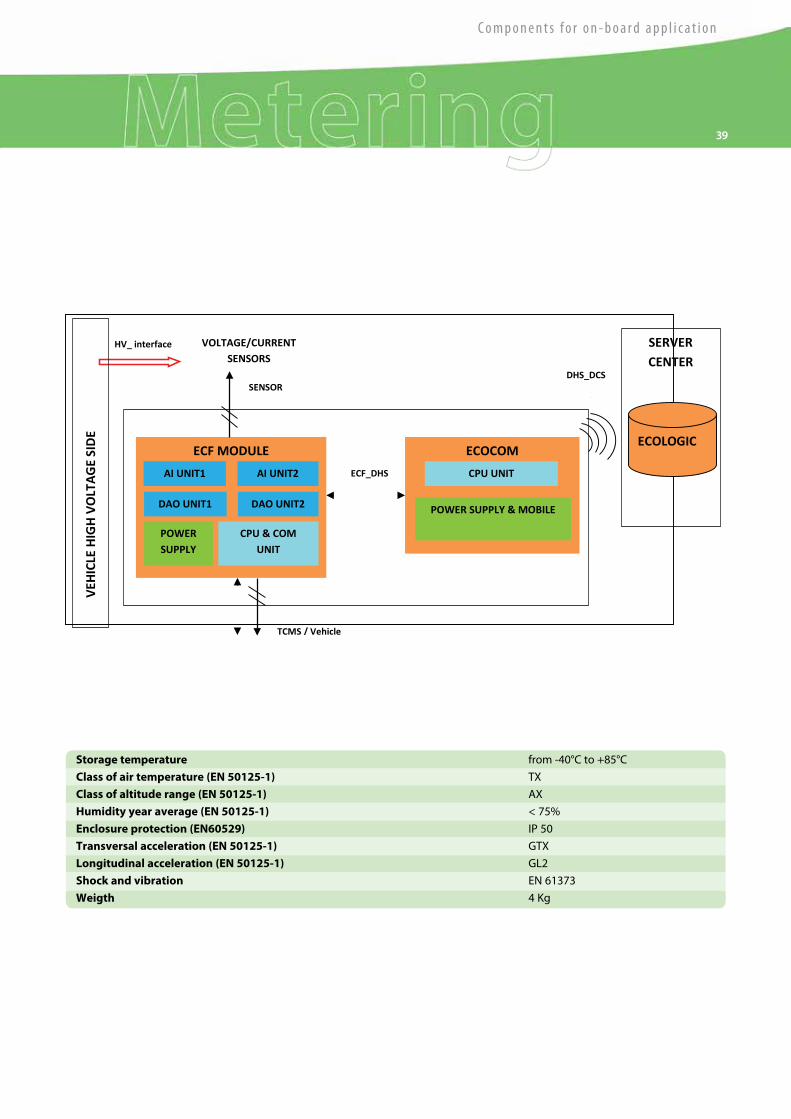
Eco ModuleGeneral Characteristics
The ECOMODULE is part of our ECOSystem Network and provide the following functions, in
accordance with the EN50463
• ECF
• DHS
The device is suitable for railway rolling stock application, assuring a very low energy
absorption, in order to be directly connected to the vehicle battery.
The ECF function performs measurements of the consumed and regenerated active or
reactive energy of a traction unit.
The energy value are calculated in compliance with EN50463 on the base of the line voltage
and the line current measured by available external sensors.
The energy data is handled by internal data handling system (DHS) to create and storage
Compiled Energy Billing Data (CEBD).
The DHS main functions is to prepare and submit the necessary information, that means
the Compiled Energy Billing Data, to the ground systems that deal with the management
of energy consumption, on the basis of the information received from the system board
measurement.
Thanks to wireless connectivity offered by the DHS, the time information and geographic
location are also made available.
38
C o m p o n e n t s f o r o n - b o a r d a p p l i c a t i o n
39
ECF MODULE
SERVER CENTER
ECOCOM
CPU UNIT
POWER SUPPLY & MOBILE
AI UNIT1
POWER SUPPLY
VOLTAGE/CURRENT SENSORS
VEH
ICLE
HIG
H VO
LTAG
E SI
DE
TCMS / Vehicle
DHS_DCS
interface
ECF_DHS
interface
SENSOR
interface
ECOLOGIC
HV_ interface
DAO UNIT2 DAO UNIT1
CPU & COM UNIT
AI UNIT2
Storage temperature from -40°C to +85°C
Class of air temperature (EN 50125-1) TX
Class of altitude range (EN 50125-1) AX
Humidity year average (EN 50125-1) < 75%
Enclosure protection (EN60529) IP 50
Transversal acceleration (EN 50125-1) GTX
Longitudinal acceleration (EN 50125-1) GL2
Shock and vibration EN 61373
Weigth 4 Kg

ThepsysGeneral Characteristics
Thepsys is a device that has a diagnostics function able to detect power supply failure
or thermocouple break. The main feature of the device is the galvanic insulation between
HV and LV sections, made by means of a transformer (insulation level, 15kV-50Hz-60s)
which feeds the HV section and transmits the signal (proportional to the temperature)
to the low voltage section via an optical channel; the signal is then elaborated in order
to drive the various outputs foreseen.
Functions
Thepsys functions are highly customizable according to our customer needs
as well as suggestions derived from our experience.
• Measured temperature
• Diagnostic relay contact
• Alarm relay contact
• Analog output
Environmental Performance
The device is compliant with all regulations of the rail market. All the components are
homologated for the industrial temperature range (from -40°C to +85°C - Class TX - EN 50125-1)
and ensure a proper working in the worst environmental conditions. The precision is 1%
on the whole TX range; 0.5% at 23°C.
Storage temperature from -40°C to +85°C
Class of air temperature (EN 50125-1) TX (from -40°C to +85°C)
Class of altitude range (EN 50125-1) A1 (up to 1400m)
Maximum Relative humidity at 40°C 95%
Protection level for terminal box (EN6 0529) IP 66
Shock and vibrations EN 61373 Shock and vibrations
Consumption 8W typically
Measurements range 0°C to 1000°C
Thermocouple accuracy ± 1% over max scale 1000°C
Measurements accuracy 30°C
Analogic output accuracy Class 1
Battery supply 24V - 72V - 110V
Weight 3kg
40

Overall Dimensions (mm)
Functional Scheme
3 sec Max
POWER UP
M9/M11
3 sec Max
3 sec Max
TRIGGER= XXX°
Alarm Relay OFF M9 - M11 OPEN
diagnostic Relay ON M12 - M13 closed
Example Temp. evolution TH1 Temp. evolution TH2
closed
95
10
1020
0
220
65
225
52.5 120
280
175
87.5
Ø 7 4x
C o m p o n e n t s f o r o n - b o a r d a p p l i c a t i o n
41

42 Direct driven axial fans
Applications
Aircoolers
Heat exchangers / Radiators
Cooling of electrical machines (motors, converters, inductors, generators, transformers)
Naval
Ventilation and Air Conditioning Plants
The medium performance “AF” and “LA” fan Series were designed to meet the majority
of cooling and ventilation requirements typical of industrial applications. They were conceived
to provide the best mix of reliability, versatility, performance, quality, environmental impact
and cost. All of these products have features making them easily compliant with the most
widespread technical specifications and allowing significant modification based on specific
customer requirements. Direct-coupling solutions with motors from 2 to 16 poles are
available, to suit fan performance and noise requirements. Belt-driven solutions with larger
diameters and selected speed are also available (see “AFT”).
The “AF” and “LA” Series are versatile and reliable, characteristics that make them the COMET’s
most successful products, suitable for the most frequent ventilation needs. COMET “AF”
and “LA” Series of fans have proved their efficiency every day in over 60 countries worldwide,
in extreme climates, harsh environments and a wide range of temperatures for the most
demanding operations.
These Series of fans are selected using COMET’s dedicated software, based upon the results
of a huge number of tests performed by COMET on test tunnels and actual installations.
The selection is based on five blade profiles in aluminium alloy, and others in fiberglass
or polipropylene, with number of blades varying between 3 and 12 blades.
General Characteristics
AF/LA Series
AF
• Impellers with aerofoil profile blades in extruded alluminium alloy low-noise type
• Adjustable blade pitch when standstill
• Three-phase motors IP55 with Class F or H insulation, 50/60Hz, 2-16 pole, from the best
European manufacturers
• Casings in carbon steel, electro-welded, with anti-corrosive finishing by hot-dip
galvanization
Wide range of ancillary parts and customizations
Special versions with special materials, certified components, motors according
to customer’s specifications.
Impellers in PPG, FRP or steel are available upon request
LA
• Impellers with aerofoil profile blades in PPG, low-noise type
• Three-phase motors IP55 with Class F insulation
• Casings in carbon steel, electro-welded
• Finishing by hot-dip galvanization : longer durability in harsh environment

43
C o m p o n e n t s f o r o n - b o a r d a p p l i c a t i o n
Series Diameter [mm] Air Flow Pressure Power [kW]
AF 400 ÷ 2400 up to 400000mc/h up to 1500Pa 0.55 ÷ 90
LA 310 ÷ 800 up to 35000mc/h up to 800Pa 0.25 ÷ 7.5
Technical Data
AFLA

44 High performances axial fans
Applications
Brake resistors
Heat exchangers / radiators
Gas turbine enclosures
Forced ventilation
Traction motors
High quality, no-compromise products for applications requiring a guaranteed and reliable
component providing high pressures and precise air flows. They are most suitable for
applications which require the fan to be a critical part of the system both in terms of
performance and reliability. They are used in different applications such as power generation,
railway, naval, cement and are always characterized by the demanding and critical nature of
the service. Direct coupling solutions with motors from 2 to 8 poles are available, as well as
belt-driven solutions for all cases in which it is convenient to decouple the motor from the
impeller for service or maintenance. Only top quality components, sized by COMET according
to criteria based on 15 years of experience and many industrial applications, are used for the
manufacturing of these units. Detailed aerodynamic studies are the basis of the design of the
“AFH” Series fans, which feature key characteristics for use in critical applications:
• above average pressures and air flows
• reduced dimensions
• moderate noise
• high reliability
• cost effective solution
The “AFH” Series is the ideal choice when looking for a high performance product of superior
quality.
• Impellers with high-efficiency, low-noise aerofoil type blades, in alluminium alloy
• Three-phase motors IP55/IP65, with Class F or H insulation, 50/60Hz, suitable
for inverter supply
• Casings in carbon steel, electro-welded, with anti-corrosive finishing
by hot-dip galvanization
• Single or double array of fixed vanes for performance increase, optimized
for the application
Wide range of ancillary parts and customizations
Versions with special materials, special dimension, motors according to customer’s
specifications.
Double-stage or double-impeller solutions for higher performances are available upon
request
General Characteristics
AFHSeries

45
C o m p o n e n t s f o r o n - b o a r d a p p l i c a t i o n
Technical data
Series Diameter [mm] Characteristics Pressure Power [kW]
AFH 360 ÷ 1800 Direct drive up to 2800Pa 0.55 ÷ 90
(single stage)
up to 4000Pa
(double stage)
AFTH 630 ÷ 1800 Belt drive up to 2500Pa 1.5 ÷ 55
(single stage)
AFH

46
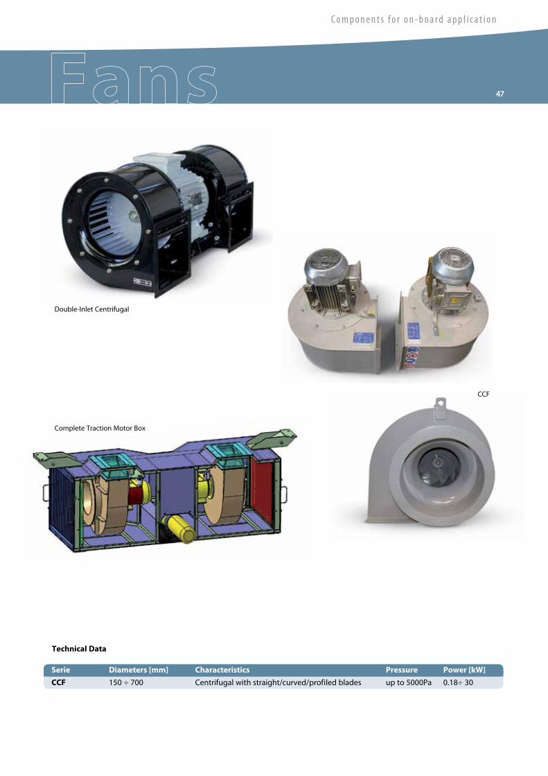
• Impellers in carbon steel, stainless steel or alluminium, with straight, curved
or profiled blades
• Three-phase motors IP55/IP65, with Class F or H insulation, 50/60Hz, suitable for
inverter supply
• Fan cowls in carbon steel or stainless steel, electro-welded
• Finishing by 3-layers epoxy-pack painting, certified for 500 hours salt mist test resistance
Wide range of ancillary parts and customizations
Versions with special materials, special dimension, motors according
to customer’s specifications.
Double-inlet or double-impeller solutions are available upon request
General Characteristics
COMET’s centrifugal fan Series are mainly intended for use in critical applications where
guaranteed performance and high reliability are required.
The production range includes several types of fans and Series of impellers, based upon
our wide know-how in the design and manufacturing of dedicated and engineered fan
solutions. All COMET’s centrifugal units have been designed to reach high levels of reliability
and versatility, and they are characterized by a compact design and wide possibilities of
customization.
Impellers with straight, curved and profiled blades are available on all types of centrifugal
fans. Furthermore, carbon steel, stainless steel or alluminium, can be used for the
manufacturing, in order to always offer the most suitable solution to the vast majority of
environmental, mechanical and noise requirements.
COMET can also provide a wide range of ancillary parts and complete systems, which include
filters, dampers, supporting frames, noise insulating systems, and more.
Centrifugal fan units
Applications
Heat exchangers / radiators
Traction motors
Transformers
Converters
Filtration plants
Ventilation plants
47
C o m p o n e n t s f o r o n - b o a r d a p p l i c a t i o n
Technical Data
Serie Diameters [mm] Characteristics Pressure Power [kW]
CCF 150 ÷ 700 Centrifugal with straight/curved/profiled blades up to 5000Pa 0.18÷ 30
CCF
Complete Traction Motor Box
Double-Inlet Centrifugal

48 Open-running centrifugal fans (plug-fans)
Ideal products for applications requiring a very compact and high-performance solution,
the open-running centrifugals (OR Series) eliminate some typical limits of the traditional
centrifugal fans. The compact dimension and the absence of a preferential direction
of the airflow make these fans very useful wherever high pressures must be generated
in a small space and a 90° change of direction of the airflow is not recommended.
They are the optimal solution for the forced ventilation of limited environments
(like boxes containing electrical or electronic equipments).
ORV Series fans are fitted with a simplified housing to separate the motor from
the flow generated by the fan (e.g. applications with air temperature higher than 60°C).
Ready-to install and innovative, the COR Series features an extremely compact design,
due to an exclusive fixation system of the electric motor.
Derived from the technology of COMET’s centrifugal fan units, the impellers used
on OR/COR/ORV Series can be made of carbon steel, aluminum or stainless steel,
with straight, curved or profiled blades.
OR/COR/ORV Series
Applications
Heat exchangers / radiators
Traction motors
Transformers
Converters
Ventilation plants
• Three-phase motors IP55/IP65, with Class F or H insulation, 50/60Hz, suitable
for inverter supply
• Impellers in carbon steel, stainless steel or alluminium, with straight, curved
or profiled blades
• Finishing by 3-layers epoxy-pack painting, certified for 500 hours salt mist test resistance
• Special motors and special fixation system for COR Series
Versions with special materials, special dimension, motors according to customer’s
specifications.
General Characteristics

49
C o m p o n e n t s f o r o n - b o a r d a p p l i c a t i o n
Technical Data
Series Diameters [mm] Characteristics Pressure Power [kW]
OR 150 ÷ 500 Open-Running Centrifugal (Plug-Fan) up to 3000Pa 0.18 ÷ 22
COR 200 ÷ 500 Compact Open-Running up to 2500Pa 0.37 ÷ 15
Centrifugal, with fixing plate
ORV 200 ÷ 500 Open-Running Centrifugal up to 3000Pa 0.55 ÷ 22
with simplified housing
OR
COR

50 Centraxial and Mixed Flow Fans
Applications
Traction motors
Brake resistors
Forced ventilation systems
Designed to combine the high pressure levels obtained by the centrifugal fans with the
advantages of size and ease of installation given by the axials, the CNX and MXF Series are
based on COMET’s decades of experience in the design and production of high-performance
axial fan units.
The CNX and MXF Series provide maximum pressures which are 50% higher than those of
the correspondent axial, in their typical range of airflows. This is achieved with dimensions
comparable to those of a conventional axial fan.
Besides the advantage in terms of performances, these products also offer distinct low-noise
characteristics. Sound emissions are comparable to centrifugal units, allowing in many cases
to avoid the use of silencers or reducing the impact of noise insulation systems.
This is offered together with the usual flexibility of design and construction which
characterizes COMET’s products, making them suitable for the most demanding applications
and critical duties.
CNX/MXF Series
• Impellers in carbon steel, stainless steel or alluminium, with straight, curved
or profiled blades
• Three-phase motors IP55/IP65, with Class F or H insulation, 50/60Hz, suitable
for inverter supply
• Casings in carbon steel or stainless steel, electro-welded
• Finishing by 3-layers epoxy-pack painting, certified for 500 hours salt mist test resistance,
or hot-dip galvanization
• Single or double array of fixed vanes for performance increase, optimized
for the application
Wide range of ancillary parts and customizations
Versions with special materials, special dimension, motors according
to customer’s specifications.
General Characteristics

51
C o m p o n e n t s f o r o n - b o a r d a p p l i c a t i o n
Technical Data
Series Diameters [mm] Characteristics Pressure Power [kW]
CNX 400 ÷ 1400 Centraxial up to 4500Pa 1.5 ÷ 55
MXF 300 ÷ 800 Mixed-Flow up to 4000Pa 1.5 ÷ 45
CNX
CNX
5020
710 -
INB
- Rev
. Sep
tem
ber 2
014
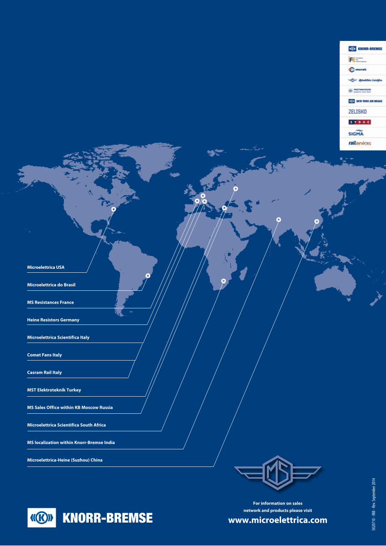
For information on sales
network and products please visit www.microelettrica.com
Microelettrica USA
Microelettrica do Brasil
MS Resistances France
Heine Resistors Germany
Microelettrica Scientifica Italy
Comet Fans Italy
Casram Rail Italy
MST Elektroteknik Turkey
MS Sales Office within KB Moscow Russia
Microelettrica Scientifica South Africa
MS localization within Knorr-Bremse India
Microelettrica-Heine (Suzhou) China


