65
Components of Thermodynamic Cycles What can be the components of thermodynamic cycles? Turbines, valves, compressors, pumps, heat exchangers (evaporators, condensers), mixers,
| Date post: | 17-Dec-2015 |
| Category: |
Documents |
| Upload: | kristin-gibbs |
| View: | 261 times |
| Download: | 0 times |

Components of Thermodynamic Cycles What can be the components of thermodynamic cycles? Turbines, valves, compressors, pumps, heat exchangers
(evaporators, condensers), mixers,

BUTTERFLY VALVE
SPHERE VALVE
GLOBE VALVE
PIPE CRACK
GATE VALVE

Th
rott
lin
g D
evic
es (
Val
ves)
Th
rott
lin
g D
evic
es (
Val
ves)
Typical assumptions for throttling devicesTypical assumptions for throttling devices1. No work2. Potential energy changes are zero3. Kinetic energy changes are usually small4. Heat transfer is usually small5. Two port device

Look at energy equation:Look at energy equation:
Apply assumptions from previous page:
0 0 00
We obtain: or
Does the fluid temperature:increase, decrease, or
as it goes through an adiabatic valve?
remain constant

Look at implications:Look at implications: If the fluid is liquid/vapor:
During throttling process:
• The pressure drops,
• The temperature drops,
• Enthalpy is constant
s
T
h const.
h const.
P const.

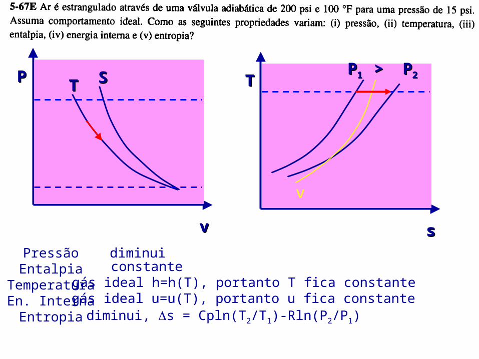
Look at implications:Look at implications: if fluid is an ideal gas:
Cp is always a positive number, thus:
PP
vv
SSTT
diminuiPressãoEntalpia
TemperaturaEn. Interna
Entropia
constantegás ideal h=h(T), portanto T fica constantegás ideal u=u(T), portanto u fica constante
TT
ss
v
PP1 1 > P> P22
diminui, s = Cpln(T2/T1)-Rln(P2/P1)

s, kJ/(kgK)
T (K
)
15M
Pa
611K (340oC)
373K (100oC)

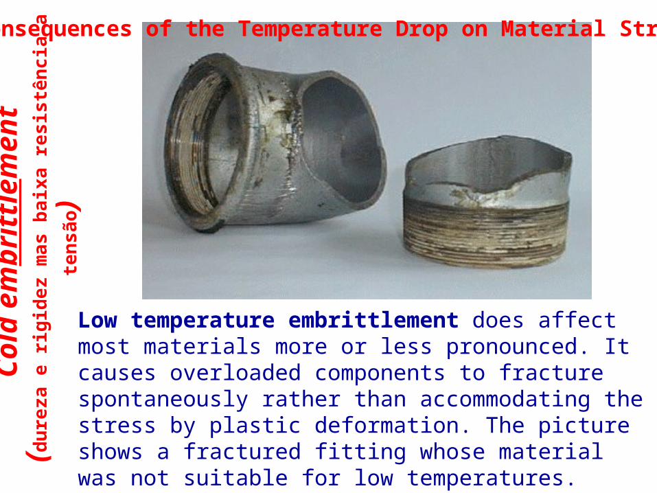
Cold embrittlement (dureza e rigidez mas baixa resistência a tensão)
T-1000 (Robert Patrick)
Col
d em
brit
tlem
ent
(du
reza
e r
igid
ez m
as b
aixa
res
istê
nci
a a
ten
são)
Low temperature embrittlement does affect most materials more or less pronounced. It causes overloaded components to fracture spontaneously rather than accommodating the stress by plastic deformation. The picture shows a fractured fitting whose material was not suitable for low temperatures.
Consequences of the Temperature Drop on Material Strenght

TEAMPLAYTEAMPLAYRefrigerant 12 enters a valve as a saturated liquid at 0.9607 Mpa and leaves at 0.1826 MPa. What is the quality and the temperature of the refrigerant at the exit of the valve?
State (1)Liquid saturated, x=0Psat = 0.9607 MPaTsat = ?Hliq = ?
State (2)Liq+vap x=?Psat = 0.1826 MPaTsat = ?Hliq = ?
40oC75kJ/kg
-15oC22 & 180 kJ/kg
0.33

P-h
Dia
gram
of
an I
deal
Vap
or-
P-h
Dia
gram
of
an I
deal
Vap
or-
Com
pres
sion
Ref
rige
rati
on C
ycle
Com
pres
sion
Ref
rige
rati
on C
ycle
Throttling
The refrigerant enters the compressor as a saturated vapor and is cooled to the saturated liquid state in the condenser. It is then throttled to the evaporatorand vaporizes as it absorbs heat from the refrigerated space.
Isentropic compression (1 to 2)
Constant pressure condensation (2 to 3)
Isenthalpic expansion (3 to 4)
Constant pressure evaporation (4 to 1)

Heat exchangers are used Heat exchangers are used in a variety of industriesin a variety of industries
Automotive - radiator Refrigeration - evaporators/condensers Power production - boilers/condensers Power electronics - heat sinks Chemical/petroleum industry- mixing processes

Something a little closer to Something a little closer to home..home..

Heat Exchangers Heat Exchangers
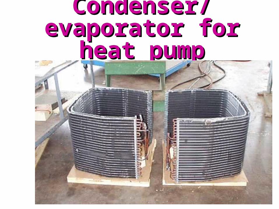
Condenser/evaporator Condenser/evaporator for heat pumpfor heat pump

Heat ExchangersHeat Exchangers Now, we must deal with multiple inlets and outlets:
1m2m
4m
3m
A21 mmm
B3 mmm 4
If we have steady flow, then:

Heat ExchangersHeat Exchangers
A
ACV zzgVV
hhmWQ
21
22
21
21 22
022 43
24
23
43
B
B zzgVV
hhm
0
0, (sometimes negligible)
0
0, (sometimes negligible)
0, (usually negligible)
0, (usually negligible)

Heat ExchangersHeat Exchangers And we are left with
)hh(m)hh(m BA 3421
The energy change of fluid A is equal to the negative of the energy change in fluid B.

SC
mvap = 0.1 kg/shvap = 2776 kJ/kg
mw = ? kg/shw = 100 kJ/kg
mc = ? kg/shc = 200 kJ/kgResp.: mw = 2.576 kg/s

Nozzles and DiffusersNozzles and Diffusers Nozzle--a device which
accelerates a fluid as the pressure is decreased.
These configuration is for sub-sonic flow.
V1, P1
V2, P2
Diffuser--a device which decelerates a fluid and increases the pressure. V1,
P1
V2, P2

Nozzles
For supersonic flow, the shape of the nozzle is reversed.

General shapes of General shapes of nozzles and diffusersnozzles and diffusers
Supersonic flow
Subsonic flow
nozzle diffuser
nozzle diffuser

conservation of energyconservation of energy
q = 0 (adiabatic)
w = 0 (these are not work producing devices; neither is work done on them)
)()( 12
21
22
12 zzg2
hhwq
VV0 0 0

Sample ProblemSample ProblemAn adiabatic diffuser is employed to reduce the velocity of a stream of air from 250 m/s to 35 m/s. The inlet pressure is 100 kPa and the inlet temperature is 300°C. Determine the required outlet area in cm2 if the mass flow rate is 7 kg/s and the final pressure is 167 kPa.
OUTLET
P2 = 167 kPa
V2 = 35 m/s
A2=?
Diffuser
INLET
T1 = 300C
P1 = 100 kPa
V1 = 250 m/s
= 7 kg/sm

Conservation of Mass: Steady State RegimeConservation of Mass: Steady State Regime
2
22
1
11 AAm
VV solve for A2
2
22
mA
V
But we don’t know v2!
Remember ideal gas equation of state?
1
1
P
RT1
2
2
P
RT2
and
We know T1 and P1, so v1 is simple. We know P2, but what about T2?
NEED ENERGY EQUATION!!!!NEED ENERGY EQUATION!!!!

Energy EqnEnergy Eqn
If we assumed constant specific heats, we could get T2 directly
2 2
1 22 1 2 1 2P
V Vh h C T T
2 22 1 1 2 2 602PT T V V C K
32 2 2RT P 1.0352m kg The ideal gas law:
4 222
2
7 1.035A 10 2070
35
mcm
V
And the area:

Vapor Power CyclesVapor Power Cycles We’ll look specifically at the Rankine
cycle, which is a vapor power cycle.
It is the primary electrical producing cycle in the world.
The cycle can use a variety of fuels.


BOILERTURBINE
PUMP
CONDENSER
q in
w out
qout
w in
1
3
42
We’ll simplify the power plantWe’ll simplify the power plant
Car
not
Vap
or C
ycle
Car
not
Vap
or C
ycle
s
T
34
1 2
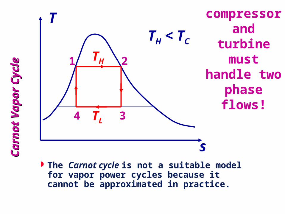
compressor and turbine must handle two phase
flows!
TL
TH
TH < TC
The Carnot cycle is not a suitable model for vapor power cycles because it cannot be approximated in practice.

Ideal power plant cycle is called the Ideal power plant cycle is called the Rankine CycleRankine Cycle
The model cycle for vapor power cycles is the Rankine cycle which is composed of four internally reversible processes:
1-2 reversible adiabatic (isentropic) compression in the pump 2-3 constant pressure heat addition in the boiler. 3-4 reversible adiabatic (isentropic) expansion through turbine 4-1 constant pressure heat rejection in the condenser

What are the main parameters we want to What are the main parameters we want to describe the cycle?describe the cycle?
pumpturout WWW Net Power
pumpturout www Net Specific Work
Efficiencyin
net
Q
W
in
net
q
wor

Start our analysis with the pumpStart our analysis with the pump
PEKEhhmWQ 12Pumppump
)( 2121pump PPhhw
The pump is adiabatic, with no kinetic or potential energy changes. The work per unit mass is:

Boiler is the next componentBoiler is the next component
PEKEhhmWQ 23boilerboiler
Boilers do no work. In boilers, heat is added to the working fluid, so the heat transfer term is already positive. So,
23boilerboiler hhqm
Q

Proceeding to the TurbineProceeding to the Turbine PEKEhhmWQ 34turbineturbine
43turbturbine hhwm
W
Turbines are almost always adiabatic. In addition, we’ll usually ignore kinetic and potential energy changes:

Last component is the CondenserLast component is the Condenser
PEKEhhmWQ 41condcond
41condcond hhqm
Q
Condensers do no work (they are heat exchangers), and if there is no KE and PE,

EfficiencyEfficiency
in
out
q
w
23
1243
hh
)P(Pvhh

Start an analysis:Start an analysis:
Assumptions:
P = 15 MPa
P = 0.01 MPa
Pump and turbine are isentropic; P2 = P3 = 150 bars = 15 MPa T3 = 600C P4 = P1 = 0.1 bars = 0.01 MPa Kinetic and potential energy changes are negligible
A Rankine cycle has an exhaust pressure from the turbine of 0.1 bars. Determine the quality of the steam leaving the turbine and the thermal efficiency of the cycle which has turbine inlet pressure of 150 bars and 600C.

Put together property dataPut together property dataState T (C) P(MPa) v(m3/kg) h(kJ/kg)
s(kJ/kgK)
x
1 0.01 0
2 15 n.a.
3 600 15 ----
4 0.01 ----
Pump (1 to 2) -> isoentropic (const. volume)Boiler [heat exchanger] (2 to 3) -> const. pressure
Turbine (3 to 4) -> isoentropic Condenser [heat-exchanger] (4 to 1) -> const. pressure

Pro
pert
y D
ata
Pro
pert
y D
ata
State T (C) P(MPa) v(m3/kg) h(kJ/kg)
s(kJ/kgK)
x
1 45.81 0.01 0.00101 191.83 0
2 49.42 15 0.00101 206.93 Liq. comp
3 600 15 0.02491 3582.3 6.6776 Super aquec
4 45.81 0.01 12.266 2114.9 6.6776 0.8037
P = 15 MPa
P = 0.01 MPa

Let start Let start with pump with pump
workwork
2121pump hh)P(Pw
15)MPa (0.01kg
m001010w
3
pump ).(
kg
kJ115w pump .
P = 15 MPa
P = 0.01 MPa

More calculations...More calculations...Enthalpy at pump outlet:
pump12 whh
kg
kJ11583191h2 )..(
Plugging in some numbers:
kg
kJ93206h2 .

How Can I Get The Pump How Can I Get The Pump Outlet Temp?Outlet Temp?
If the Enthalpy at pump outlet is 206.93 KJ/kg, then consider the compressed liquid a the same temperature of the saturated liquid which has h = 206.93 KJ/kg
Interpolating from the saturated steam table one finds: 49oC

Calculate Calculate heat inputheat input
kg
kJ9320633582hhq 23boiler )..(
kg
kJ43375qboiler .
P = 15 MPa
P = 0.01 MPa

Turbine Turbine workwork
Turbine work: turbine 3 4
kJw h h (1467.4)
kg
kJ/kg92114h 80370x
KkJ/kg67766ss
44
34
.;.
.
Isentropic:
P = 15 MPa
P = 0.01 MPa

Overall thermal efficiencyOverall thermal efficiency
in
pumpturbine
q
ww
4300
kg
kJ3375.4
kg
kJ115(1467.4
.).

Some general characteristics Some general characteristics of the Rankine cycleof the Rankine cycle
Low condensing pressure (below atmospheric pressure)
High vapor temperature entering the turbine (600 to 1000C)
Small backwork ratio (bwr)
010hh
hh
w
wWRB
43
21pump
turbine
.
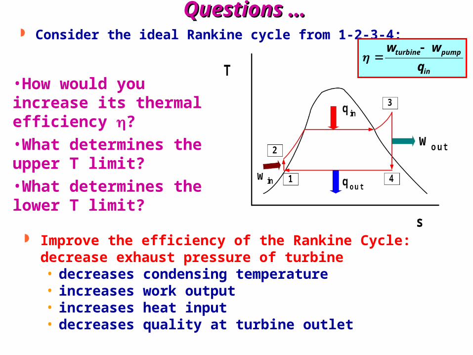
Questions …Questions … Consider the ideal Rankine cycle from 1-2-3-4:
•How would you increase its thermal efficiency ?
•What determines the upper T limit?
•What determines the lower T limit?
Improve the efficiency of the Rankine Cycle: decrease exhaust pressure of turbine• decreases condensing temperature• increases work output• increases heat input• decreases quality at turbine outlet
in
pumpturbine
q
ww

Lowering Turbine Exit PressureLowering Turbine Exit PressureLowering Turbine Exit PressureLowering Turbine Exit Pressure
The average temperature during heat rejection can be decreased by lowering the turbine exit pressure.
Consequently, the condenser pressure of most vapor power plants is well below the atmospheric pressure.
in
pumpturbine
q
ww

Reducing Condenser PressureReducing Condenser Pressure Notice that reducing the
condenser pressure (which will lower the temperature of heat rejection and again increase the efficiency) will also reduce the quality of the steam exiting the turbine.
Turbines do not like to see water coming out the exhaust.
Lower qualities mean water droplets are forming before the steam leaves the turbine.
Water droplets lead to turbine blade erosion.
Efforts are made to keep the quality > 90%.
net
in
w
q

Raising Boiler PressureRaising Boiler PressureRaising Boiler PressureRaising Boiler Pressure
The average temperature during heat addition can be increased by raising the boiler pressure or by superheating the fluid to high temperatures.
There is a limit to the degree of superheating, however, since the fluid temperature is not allowed to exceed a metallurgically safe value.
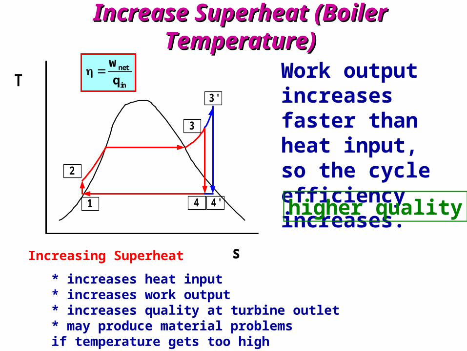
Increase Superheat (Boiler Temperature)Increase Superheat (Boiler Temperature)
T
s
1
2
3
4 4'
3'
Work output increases faster than heat input, so the cycle efficiency increases.
higher quality
net
in
w
q
Increasing Superheat
* increases heat input* increases work output* increases quality at turbine outlet* may produce material problems if temperature gets too high

Effect of Increasing Boiler Pressure on Effect of Increasing Boiler Pressure on the Ideal Rankine cycle keeping constant the Ideal Rankine cycle keeping constant
the Boiler Outlet Temperature Tmaxthe Boiler Outlet Temperature Tmax
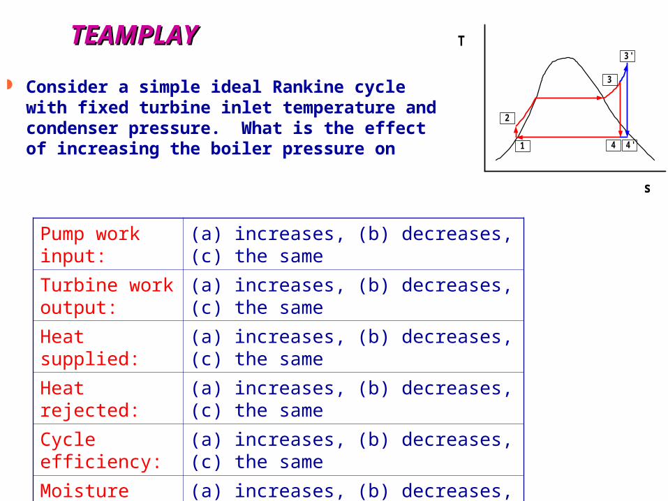
TEAMPLAYTEAMPLAY
Consider a simple ideal Rankine cycle with fixed turbine inlet temperature and condenser pressure. What is the effect of increasing the boiler pressure on
Pump work input: (a) increases, (b) decreases, (c) the same
Turbine work output:
(a) increases, (b) decreases, (c) the same
Heat supplied: (a) increases, (b) decreases, (c) the same
Heat rejected: (a) increases, (b) decreases, (c) the same
Cycle efficiency: (a) increases, (b) decreases, (c) the same
Moisture content at turbine exit:
(a) increases, (b) decreases, (c) the same
T
s
1
2
3
4 4'
3'

Simple schematic of Simple schematic of Rankine reheat cycleRankine reheat cycle
BOILER
HighPressureTURBINE
PUMP
CONDENSER
q inhi
w outhi
qout
w in
1
3
4
2
5
w outlo
6
LowPressureTURBINE
q inlo

The Ideal Reheat The Ideal Reheat Rankine CycleRankine Cycle

Reheat on T-s diagram:Reheat on T-s diagram:
Note that T5 < T3. Many systems reheat to the same temp (T5=T3).

CogenerationCogenerationCogenerationCogeneration The production of more than one useful form of
energy (such as process heat and electric power) from the same energy source is called cogeneration.
Cogeneration plants produce electric power while meeting the process heat requirements of certain industrial processes. This way, more of the energy transferred to the fluid in the boiler is utilized for a useful purpose.
The fraction of energy that is used for either process heat or power generation is called the utilization factor of the cogeneration plant.

An Ideal Cogeneration PlantAn Ideal Cogeneration PlantAn Ideal Cogeneration PlantAn Ideal Cogeneration Plant

Schematic and T-s Diagram Schematic and T-s Diagram for Cogenerationfor Cogeneration
Schematic and T-s Diagram Schematic and T-s Diagram for Cogenerationfor Cogeneration

Combined Gas-Steam Combined Gas-Steam Power PlantPower Plant
Combined Gas-Steam Combined Gas-Steam Power PlantPower Plant


![[Flip-Side] 3. Thermodynamic Cycles](https://static.documents.pub/doc/80x56/56d6c06d1a28ab30169a58c7/flip-side-3-thermodynamic-cycles.jpg)
