COMOS Process FEED Administration Operating Manual 11/2013 A5E32035546-AA Process simulators 1 Assigning units between Aspen Plus or ProMax and COMOS 2 Modifying the standard import 3 Creating and grouping pure components under the "Pure components" folder 4 Tips for base data administrators 5 Base data reference 6 Project properties reference 7
Transcript
COMOS
ProcessFEED Administration
Operating Manual
11/2013A5E32035546-AA
Process simulators 1
Assigning units between Aspen Plus or ProMax and COMOS
2
Modifying the standard import 3
Creating and grouping pure components under the "Pure components" folder
4
Tips for base data administrators
5
Base data reference 6
Project properties reference 7
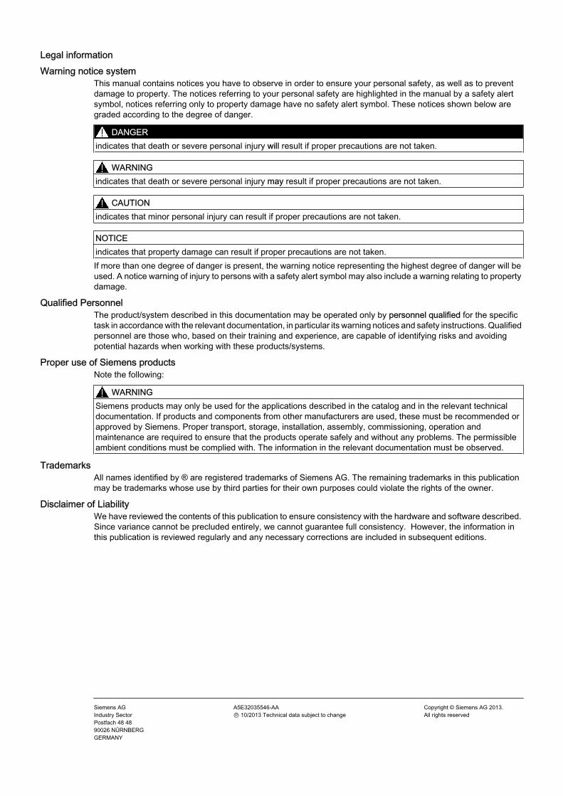
Legal informationWarning notice system
This manual contains notices you have to observe in order to ensure your personal safety, as well as to prevent damage to property. The notices referring to your personal safety are highlighted in the manual by a safety alert symbol, notices referring only to property damage have no safety alert symbol. These notices shown below are graded according to the degree of danger.
DANGER
indicates that death or severe personal injury will result if proper precautions are not taken.
WARNING
indicates that death or severe personal injury may result if proper precautions are not taken.
CAUTION
indicates that minor personal injury can result if proper precautions are not taken.
NOTICEindicates that property damage can result if proper precautions are not taken.If more than one degree of danger is present, the warning notice representing the highest degree of danger will be used. A notice warning of injury to persons with a safety alert symbol may also include a warning relating to property damage.
Qualified PersonnelThe product/system described in this documentation may be operated only by personnel qualified for the specific task in accordance with the relevant documentation, in particular its warning notices and safety instructions. Qualified personnel are those who, based on their training and experience, are capable of identifying risks and avoiding potential hazards when working with these products/systems.
Proper use of Siemens productsNote the following:
WARNING
Siemens products may only be used for the applications described in the catalog and in the relevant technical documentation. If products and components from other manufacturers are used, these must be recommended or approved by Siemens. Proper transport, storage, installation, assembly, commissioning, operation and maintenance are required to ensure that the products operate safely and without any problems. The permissible ambient conditions must be complied with. The information in the relevant documentation must be observed.
TrademarksAll names identified by ® are registered trademarks of Siemens AG. The remaining trademarks in this publication may be trademarks whose use by third parties for their own purposes could violate the rights of the owner.
Disclaimer of LiabilityWe have reviewed the contents of this publication to ensure consistency with the hardware and software described. Since variance cannot be precluded entirely, we cannot guarantee full consistency. However, the information in this publication is reviewed regularly and any necessary corrections are included in subsequent editions.
1 Process simulators.......................................................................................................................................7
2 Assigning units between Aspen Plus or ProMax and COMOS....................................................................9
3 Modifying the standard import....................................................................................................................11 3.1 Overview of the topic "Modifying the standard import"................................................................11 3.2 Buttons for import objects............................................................................................................11 3.3 Simulation objects ......................................................................................................................12 3.3.1 Import()........................................................................................................................................14 3.3.2 ImportDone()...............................................................................................................................15 3.3.3 SimulatorImport().........................................................................................................................16 3.3.4 SimulatorImportDone()................................................................................................................16 3.4 Aspen Plus: Class AspenNode...................................................................................................17 3.4.1 Properties....................................................................................................................................18 3.4.2 Read().........................................................................................................................................19 3.4.3 ReadArray().................................................................................................................................21 3.4.4 CreateSubObjects().....................................................................................................................22 3.4.5 XML ValueExist().........................................................................................................................23 3.5 ProMax........................................................................................................................................25 3.5.1 Public class ProMaxNode...........................................................................................................26 3.5.2 Public class BlockNode: ProMaxNode........................................................................................27 3.5.3 Public class StreamNode: ProMaxNode.....................................................................................28 3.5.4 Public class ComponentNode: StreamNode...............................................................................29 3.6 PRO/II:Class ProIINode..............................................................................................................29 3.6.1 Properties....................................................................................................................................30 3.6.2 Read() ........................................................................................................................................31 3.6.3 ReadArray() ................................................................................................................................32 3.6.4 ReadArrayToFewSpecs() ...........................................................................................................33 3.6.5 ReadSI() .....................................................................................................................................33 3.6.6 GetComosSpecArray() ...............................................................................................................34 3.6.7 Functions that are used internally ..............................................................................................34 3.7 HYSYS: Class HYSYSNode.......................................................................................................35 3.7.1 Properties ...................................................................................................................................36 3.7.2 HYSYSClass() ............................................................................................................................37 3.7.3 LiquidPhase1() ...........................................................................................................................37 3.7.4 LiquidPhase2()............................................................................................................................37 3.7.5 Read() ........................................................................................................................................37 3.7.6 ReadPhase .................................................................................................................................38 3.7.7 VaporPhase() .............................................................................................................................38 3.8 UniSim Design: Class UniSimNode............................................................................................38 3.9 EbsilonProfessional: Class EbsilonNode....................................................................................38 3.9.1 Properties....................................................................................................................................39 3.9.2 GetEbsKind()...............................................................................................................................39
3.9.3 Read().........................................................................................................................................39 3.9.4 ReadNumeric()............................................................................................................................40 3.10 ChemCad: Class ChemCad Node..............................................................................................40 3.10.1 Properties....................................................................................................................................41 3.10.2 GetChemCadClass()...................................................................................................................42 3.10.3 ReadNumeric()............................................................................................................................42 3.10.4 ReadEquilibriumReactionPar()....................................................................................................42 3.10.5 ReadStreamComponents............................................................................................................43 3.10.6 FillTrayStreamList.......................................................................................................................43 3.11 Default settings for the simultaneous import of multiple files......................................................43 3.12 Setting margins for automatic placing of equipment on reports .................................................44 3.13 Excluding certain simulation types from the import.....................................................................44 3.14 Adapting an HTRI import/export..................................................................................................45
4 Creating and grouping pure components under the "Pure components" folder.........................................47
5 Tips for base data administrators...............................................................................................................49 5.1 Tips on process units..................................................................................................................49 5.2 Tips on boundary streams...........................................................................................................49 5.3 Checking the links of the equipment attributes............................................................................49
Process simulators 1Supported process simulators (software name – publisher – version – type of data exchange)
● AspenTech - HYSYS - Version HYSYS 3.1 or 3.2, 2004, 2006 - Com
● AspenTech - AspenPlus - Version 10.x - XML
● ProMax - Bryan Research & Engineering, Inc. - Version 3 - XML
● PRO/II - Invensys Operations Management - Version PRO/II 6.01 to 8.3 - Com
● EbsilonProfessional - Evonik Energy Services GmbH - Version 6.1, 7.1, 8.0 - Com
● UniSim Design - Honeywell Process Solutions - Version R360, R380, R390 - Com
● ChemCad - Chemstations Inc.- Version 5.5 to 6.3.2 - Com
Heat exchangers (software name – publisher – version – type of data exchange)HTRI - Heat Transfer Research Inc. - Version 3.0, 4.0, 5.0, 6.0 - Com
Designation in the manual● The software product HYSYS is a product of the AspenTech company, and is referred to
simply as HYSYS in the rest of this document.
● The software product AspenPlus is a product of the AspenTech company, and is referred to simply as AspenPlus in the rest of this document.
● The software product ProMax is a product of the Bryan Research & Engineering company, and is referred to simply as ProMax in the rest of this document.
● The software product PRO/II is a product of the Invensys Operations Management company, and is referred to simply as PRO/II in the rest of this document.
● The software product EbsilonProfessional is a product of the company Evonik Energy Services GmbH, and is referred to simply as EbsilonProfessional in the rest of this document.
● The software product UniSim Design is a product of the Honeywell Process Solutions company, and is referred to simply as UniSim in the rest of this document.
● The software product ChemCad is a product of the Chemstations Inc. company, and is referred to simply as ChemCad in the rest of this document.
Column Description"Name" This column contains the units as they are defined in XML in the "unit" attributes of a node."Value1" This column contains the name of the assigned COMOS unit as defined in the COMOS
unit system.
Additional information about Aspen PlusBelow this standard table, additional standard tables are defined which help to differentiate between Aspen Plus units that belong to multiple unit groups. The unit groups are defined in XML using the "domain" attribute. The name of this table corresponds to the name of the "domain" attribute, e.g. "Y40 > M21 > A10 > Y40M21N00003 Aspen units for domain HEAD".
Modifying the standard import 33.1 Overview of the topic "Modifying the standard import"
Functions controlling the sequence of the import operation are defined in the "Script" tab of the base objects of the import documents, the simulation objects, and the buttons that start the import steps.
In the database, these functions call the standard import operation.
ModificationHowever, you have the option of modifying the standard import operation by extending the functions via the script. In this way you can, for example, import attributes that are not considered by the standard import, or change the way the attributes are assigned in comparison to the standard import.
In the script, the full scope of the standard COMOS script functions is available.
See alsoButtons for import objects (Page 11)
Simulation objects (Page 12)
3.2 Buttons for import objectsIn the "Import data" tab, the import documents have various buttons that launch the individual import steps.
Each of these buttons has an OnClick() script that controls the import step in question. The buttons available differ depending on the import document.
The following commands within the OnClick() script start the standard import:
● "BU001 Start import":Workset.lib.pe.Simulation.StartImport ThisObjectStarts the first import step.StartImport() creates an instance, calls its Import(), and transfers the CDevice of the import object as a parameter.
● "BU002 Start partial import":Workset.lib.pe.PeScript.Simulation.StartPartialImport ThisObjStarts the partial import, during which the import objects can be selected individually.
● "BU003 Create PFD objects":Workset.lib.pe.Simulation.CreatePFDObjects ThisObjectStarts the second import step.
● "BU004 Place PFD equipment":Workset.lib.pe.Simulation.PlaceObjectsOnPFD1 owner.owner, NothingStarts the third import step.
● "BU005 Place PFD streams":Workset.lib.pe.Simulation.PlaceStreamOnPFD1 owner.ownerStarts the fourth import step.
● "BU006 Objects on sub flow sheets"Workset.lib.Pe.PlaceObjectsOnMultiplePFD GetSpecOwner, GetSpecOwner.spec("M21Y00T026.Y00A01382").LinkObject, true Creates additional PFDs and places equipment on sub-flow charts.
If necessary, adapt the scripts using additional commands. Delete the commands only if you want to replace the standard import completely with your own import.
However, the actual modification of the standard import function takes place in the user script blocks of the simulation objects.
3.3 Simulation objects
FunctionsEach base object below "@30 > M21 > A50 > A10 > A30 Simulation objects" defines multiple functions in the "Script" tab. These functions control what happens with this object during the first two import steps.
The start of the function body calls the standard import function for the object. You can extend the standard import in the subsequent lines.
ReferencesSee also:
● Chapter Aspen Plus: Class AspenNode (Page 17)
● Chapter ProMax (Page 25)
● Chapter HYSYS: Class HYSYSNode (Page 35)
● Chapter PRO/II:Class ProIINode (Page 29)
● Chapter UniSim Design: Class UniSimNode (Page 38)
● Chapter EbsilonProfessional: Class EbsilonNode (Page 38)
● Chapter ChemCad: Class ChemCad Node (Page 40)
This way you can, for example, import attributes that are not imported via the standard import, or change the way in which attributes are assigned compared with the standard import.
Do not delete the call for the standard import.
Modifying the standard import3.3 Simulation objects
ExceptionThe standard import operation should not be executed at all for this object but is replaced completely by a script that is defined in the function.
This involves the following functions:
Function Description[InterfaceName]Import(Node)
This function is called for each simulation object shortly before the end of the first import step. See also chapter Import() (Page 14).A reference to the node object of the simulation object is transferred as a parameter.You can use this function to import attributes that are not imported by the standard import. You have to consider that these attributes must exist on the simulation object and its PFD object. If this is not the case, they must be created in the base data beforehand.If you want to modify how attributes are assigned in the standard import, you need to undo the value assignments made via the standard import in the script before reassigning the attributes as required. Following applies in both cases: In order to also pass the modified settings for the standard import to the PFD object, the attribute linking between the simulation object and PFD object must be modified accordingly. If new attributes were added, you may need to modify the report templates of evaluating reports that should work with these attributes.
[InterfaceName]ImportDone(Node)
Called once the Import() function for all simulation objects has been executed and is responsible for post-calculations. A reference to the node object of the simulation object is transferred as a parameter.Example: Conversion of the molar density into mass density.See also chapter ImportDone() (Page 15).
SimulatorImport(DevSimObj) This function is called for each simulation object in the second import step. A reference to the import object is transferred as a parameter.See also chapter SimulatorImport() (Page 16).
SimulatorImportDone(devPFDObj, DevSimObj)
Called once the SimulatorImport() function for all simulation objects has been executed and is responsible for post-calculations. A reference to the import object is transferred as a parameter.See also chapter SimulatorImportDone() (Page 16).
Modifying the standard import3.3 Simulation objects
Call standard importSet SimulatorImport =Workset.lib.pe.simulator. ImportDone(devPFDObj, devSimObj)
3.4 Aspen Plus: Class AspenNode
ModificationThe first two import steps can be modified using the AspenNode class from the "Comos.Aspen.XMLImp.dll" file.
Background:
An instance of AspenNode is created for each simulation object during the import operation. This instance is a temporary object that serves as a link between COMOS (the target object = the simulation object) and AspenTech Aspen Plus (the source object = the XML node) and is only available during the import operation.
In addition, the import functions defined in the "Script" tab are called for each simulation object during the standard import operation. See also chapter Simulation objects (Page 12). For these calls the AspenNode instance which was created for the simulation object is transferred as a parameter.
The import calls can be extended and the standard inport function for the first two import steps adjusted using the functions and variables of the AspenNode instance.
The "AspenXMLImp.dll" file also contains the AspenXMLImp class.
This class is instantiated in the OnClick() script of the "BUTTON1 Start Import" button of the AspenTech Aspen Plus import object. See also chapter Buttons for import objects (Page 11).
Next, the following function of the AspenXMLImp instance is called in the script:
Sub Import(ByVal devSimulator As IComosDDevice)This function starts the import operation. A reference to the AspenTech Aspen Plus import object is transferred as a parameter.
Result of the callThe simulation objects are created below devSimulator and an instance of AspenNode is generated for each simulation object.
Modifying the standard import3.4 Aspen Plus: Class AspenNode
ComosDevicePublic ComosDevice As IcomosDDevice Reference to the simulation object whose script is currently being executed.
Example:
Node.ComosDevice.spec("Y00T00133.Y00A02301").Value Reads the value of attribute PD.CD0055 of the current simulation object.
AspenXMLNodePublic AspenXMLNode As MSXML.IXMLDOMNode Reference to the current XML source node. The declaration as MSXML.IXMLDOMNode refers to the standard Microsoft XML library.
Through this you have access to numerous XML default properties, for example:
● AspenXMLNode.SelectSingleNode(ByVal nodename as String)Selects a particular node via the name and returns the node.Example:Can be used to check whether or not a particular node exists. If Not Node.AspenXMLNode.SelectSingleNode("TSINP_SSTG") Is Nothing Then … End If
● AspenXMLNode.NodeName As String Returns the name of the current XML node as a string. Example:Can be used to execute code only for a particular node. If Node.AspenXMLNode.NodeName = "BlockRadfrac" Then…End If
IsLogActivePublic Property IsLogActive() As BooleanAllows you to turn the log texts on and off. This way, the administrator can determine which error or warning messages are to be included in the log text.
Example:
Activate the log text while a subobject is being created. If the required XML subnode does not exist, an error message is written to the log text. Node.IsLogActive = TrueNode.CreateSubObjects "B_TEMP", "Stage", "Tray"Node.IsLogActive = False
Modifying the standard import3.4 Aspen Plus: Class AspenNode
Liquidphase2The Aspen interface imports the second liquid phase for flows and column trays. This concerns the molar and mass flow and the molar and mass portion of individual components.
To this end there are the following Properties of type Boolean in class AspenNode:
● IsLightLiquidInStream
● IsHeavyLiquidInStream
● IsVapourInStream
3.4.2 Read()Public Function Read(ByVal strAspenXMLAttribute As String, ByVal strComosSpecName As String) As BooleanReads a single value from an XML node and writes it to a COMOS attribute. XML values defined by "*" are skipped during the import operation.
Parameter "strComosSpecName"Type: StringName of the target attribute.
Parameter "strAspenXMLAttribute"Type: StringA combination of the name of the XML node and a precise definition of the source value.
The definition of the source value can be made up from several blocks:
● "domain"Defines the unit groupIf the source value involves a numeric value with a unit, then a "domain" attribute must exist at the XML node. The attribute must be incorporated in the detailed definition of the source value.Exception: Multiple unit groups exist in a node. In that case "domain" has the value "MultiDomain" and is not specified in the definition of the source value.
● DimensionsAn XML node can have a one dimensional or a multi-dimensional data field. The single dimensions are defined via subnodes. Each dimension owns a collection of "items". If one item was determined for each dimension, the associated value can be determined from the "Value" subnode.
This results in the following notation for strAspenXMLAttribute:
[XMLNodeName](domain:[value], [NameDimension_1]:[value from "items"],[NameDimension_2]:[value from "items"], ...)
Modifying the standard import3.4 Aspen Plus: Class AspenNode
The precise definition of the source value is optional and depends on the structure of the XML node. The round brackets are mandatory. They are also required to be stated if the definition of the source value is omitted. The text in square brackets must be replaced by the specific values.
If a dimension is not specified, COMOS cannot determine which value is to be selected. A log entry is made.
A number of examples follow. The target attribute is Y00T00134.Y00A01355 in all examples.
No definition of the source value is required
● Name of the XML node: MW_LIQ
● The node does not have a "unit" attribute, and hence no "domain" attribute.
● In addition, the node does not have a data field but instead only a single value. Thus there are also no existing dimensions.
The definition of the source value is thus entirely omitted.
Function call:
Node.Read "MW_LIQ()", "Y00T00134.Y00A01355"
Definition of the source value for a one-dimensional data field
● Name of the XML node: TEMP_OUT
● Attribute "domain": existsValue: TEMPERATURE
● Dimensions: a dimensionSUBSTREAM: Value from "items": MIXED
3.4.3 ReadArray()Public Function ReadArray (ByVal strAspenXMLAttribute As String, ByVal strComosSpecName As String) As BooleanReads a one-dimensional data field from an XML node and writes it to the XValues of a COMOS list attribute. XML values defined by "*" are skipped during the import operation.
Parameter "strComosSpecName"Type: StringName of the COMOS list attribute.
Parameter "strAspenXMLAttribute"Type: StringSame as the parameter strAspenXMLAttribute of Read(). One dimension remains undetermined. It does not matter which dimension this is. If two or more dimensions are not
Modifying the standard import3.4 Aspen Plus: Class AspenNode
specified, the function call is under-determined. If all dimensions are determined, then Read() would be the correct function call.
Examples:
● Name of the XML node: HT_FROM_TOP2
● Attribute "domain": existsValue: LENGTH
● Dimensions: two dimensionsNPOINTS and Stage
● Case 1: NPOINTS undefined
– Function call:Node.ReadArray "HT_FROM_TOP2(domain:LENGTH, Stage:3)","Y00T00134.Y00A01355"
– Consequence: Two values are written into the XValues of list attribute Y00T00134.Y00A01355; in our example, the values from stage 3.
● Case 2: Stage undefined
– Function call:Node.ReadArray "HT_FROM_TOP2(domain:LENGTH, NPOINTS:2)","Y00T00134.Y00A01355"
● Consequence:18 values are written into the XValues, in our example the values from NPOINTS 2.
3.4.4 CreateSubObjects()Public Function CreateSubObjects(ByVal AspenXMLNodeName As String, ByVal AspenXMLSubNodeName As String, ByVal NamePrefix As String, Optional ByVal AspenSubObjClassName As String = "") As BooleanThis function creates a new simulation object underneath the current COMOS device, provided that the simulation object that is to be created does not exist already:
Modifying the standard import3.4 Aspen Plus: Class AspenNode
● AspenXMLNodeName:Name of the XML subnode underneath which you find the names of the new objects.
● AspenXMLSubNodeName:Name of the subnode of the second order. This name determines which base object is used for creation. The values of this node determine how many objects are created and what names they have.
● NamePrefix:A desired combination of alphabetical letters that is prefixed to the object name.Example:Node.CreateSubObjects "X", "COMPONENTS", "C_"
● AspenSubObjClassname:Optional parameter for determining the base object of the subobject. If nothing or an empty string is specified, "AspenXMLSubNodeName" is used for determining the base object (as before).
3.4.5 XML ValueExist()● Public Function XMLValueExists(ByVal XMLInfoStr As String) As
Boolean:Checks whether a particular XML attribute has a particular value.
● XMLInfoStr: Name of the XML attribute and the value that is being checked, as a string.
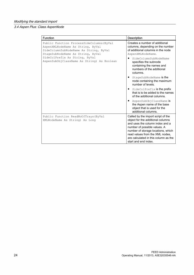
Function DescriptionPublic Function ProcessSideColumns(ByVal AspenXMLNodeName As String, ByVal SideColumnSubNodeName As String, ByVal StageSubNodeName As String, ByVal SideColPrefix As String, ByVal AspenSubObjClassName As String) As Boolean
Creates a number of additional columns, depending on the number of additional columns in the node AspenXMLNodeName.● SideColumnSubNodeName
specifies the subnode containing the names and numbers of the additional columns.
● StageSubNodeName is the node containing the maximum number of levels.
● SideColPrefix is the prefix that is to be added to the names of the additional columns.
● AspenSubObjClassName is the Aspen name of the base object that is used for the additional columns.
Public Function ReadNoOfTrays(ByVal XMLNodeName As String) As Long
Called by the import script of the object for the additional columns and uses the column index and a number of possible values. A number of storage locations, which read values from the XML nodes, are calculated in this column as the start and end index.
Modifying the standard import3.4 Aspen Plus: Class AspenNode
Function DescriptionPublic Function CreateSideColumnTrays(ByVal AspenXMLNodeName As String, ByVal AspenXMLSubNodeName As String, ByVal NamePrefix As String, ByVal AspenSubObjClassName As String) As Boolean
Creates storage locations underneath the additional columns. There is not a storage location for every entry. ● AspenXMLNodeName
(String):● AspenXMLSubNodeName
(String): Dependent on Aspen version "Stage" or "TRAY_NO"
● AspenSubObjClassName: Aspen name of the base object that is used for storage locations.
Public Function CreateColumnInternalStreams(ByVal AspenXMLNodeName As String, Optional ByVal AspenSubObjClassName As String = "") As Boolean
Creates internal processes for columns with additional columns.● AspenXMLNodeName
(String): Name of the node containing information for internal processes.
● AspenXMLSubNodeNameColumns (String): Name of the node that contains the column name.
● AspenXMLSubNodeNameStreams (String): Name of the node that contains the names of the processes.
● Optional: AspenSubObjClassName (String = ""): SIM should be used if the processes are not material processes.
3.5 ProMax
You can use the ProMaxNode class and/or the classes inherited from it BlockNode, StreamNode, and ComponentNode from the "ProMaxImport.dll" file to modify the first import step.
BackgroundAn instance of the ProMaxNode class or one of the classes inherited from it is created for each simulation object during the import operation.
This instance is a temporary object that serves as a link between COMOS (the target object = the simulation object) and ProMax (the source object = the XML node) and is only available during the import operation.
In addition, the import functions defined in the "Script" tab are called for each simulation object during the standard import operation. See also chapter Simulation objects (Page 12). For these calls, the ProMaxNode instance and/or the additional classes inherited from ProMaxNode , which were created for the simulation object, are passed as parameters.
The import calls can be extended and the standard import function for the first import step adjusted using the functions and variables of the ProMaxNode instance.
The "ProMaxImport.dll" file also contains the ProMaxImp class.
This class is instantiated in the OnClick() script of the "BUTTON1 Start import" button of the ProMax import object.
Subsequently, the following function of the ProMaxImp instance is called in the script:Sub Import(ByVal devSimulator As IComosDDevice)This function starts the import operation. A reference to the ProMax import object is transferred as a parameter.
Result of the call: The simulation objects are created underneath devSimulator and an instance of ProMaxNode or one of the classes inherited from it is generated for each simulation object.
3.5.1 Public class ProMaxNodeThe ProMaxNode class is implemented for all simulation objects.
● public IComosDDevice ComosDevice;Reference to the simulation object whose script is currently being executed.
● public XElement ProMaxXMLNode; Reference to the current XML source node.
● public string getProMaxXMLNodeName() Returns the name of the XML node.
3.5.2 Public class BlockNode: ProMaxNodeThe BlockNode class inherits from the ProMaxNode class. The BlockNode class is implemented for all simulation objects to be designated as equipment objects.
● public void createStageObjects()Creates the trays for a column.
● public void readBlock_Property(string propertyName, string ComosSpecName)Reads a single value from the properties node of the XML node and writes it to a COMOS attribute.
– Parameter "propertyName"Type: StringName of the attribute in the properties node of the XML node
– Parameter "ComosSpecName"Type: StringName of the target attribute
● public void readBlockStreamConnections()Reads out, in the XML node, the streams that are connected to the equipment and enters the data in the list of connectors in the COMOS import data. This method must be called for every equipment simulation object.
3.5.3 Public class StreamNode: ProMaxNodeThe StreamNode class inherits from the ProMaxNode class. The StreamNode class is implemented for all simulation objects to be designated as process streams or energy streams.
● public void createSubObjects(string phaseName, string compositionElement, string propertyName)Creates the COMOS components for a process stream. The input data is needed to find out how many components there are underneath the process stream.
– Parameter "phaseName"Type: StringName of the phase/the phase node in the XML node
– Parameter "compositionElement"Type: StringName of the component node in the phase node
– Parameter "propertyName"Type: StringName of the attribute in the component node
● public void readPStreamPhase_Property(string phaseName, string propertyName, string ComosSpecName)Reads a value out from the XML node and sets this in the COMOS attribute. The value provides more detailed information about an attribute of a specific phase.
– Parameter "phaseName"Type: StringName of the phase/the phase node in the XML node
– Parameter "propertyName"Type: StringName of the attribute in the phase node
– Parameter "ComosSpecName"Type: StringName of the target attribute in COMOS
● public void readStreamConnectionProperties(string connectionType, string specFrom, string specTo)Checks, in the XML node, which equipment from which direction is connected to the process stream and writes the result to the COMOS attributes.
– Parameter "connectionType"Type: StringName of the connection type in the XML node
– Parameter "specFrom"Type: StringName of the target attribute in COMOS if the connection is an incoming connection
– Parameter "specTo"Type: StringName of the target attribute in COMOS if the connection is an outgoing connection
● public Boolean existsPhaseType(string typeName) Checks whether a certain phase is available in the XML node
– Parameter "typeName"Type: StringName of the phase type
3.5.4 Public class ComponentNode: StreamNodeThe ComponentNode class inherits from the StreamNode class. The ComponentNode class is implemented for all simulation objects to be designated as process stream components.
● public void readPStreamComposition_Property(string phaseName, string propertyName, string ComosSpecName)Reads out, from a phase in the XML node, a value for all components that are available there and writes this value to the relevant COMOS attribute.
– Parameter "phaseName"Type: StringName of the phase/the phase node in the XML node
– Parameter "propertyName"Type: StringName of the attribute in the phase node
– Parameter "ComosSpecName"Type: StringName of the target attribute in COMOS
3.6 PRO/II:Class ProIINode
The first two import steps can be modified using the ProIINode class from the "Pro2Lib601.dll" file.
Modifying the standard import3.6 PRO/II:Class ProIINode
BackgroundAn instance of ProIINode is created for each simulation object during the import operation. This instance is a temporary object that serves as a link between the target object in COMOS and the source object from Invensys PRO/II and is only available during the import operation.
Analogous to the Aspen Plus import: The import functions defined in the "Script" tab are called for each simulation object in the first two import steps and the ProIINode instance created for this simulation object is transferred as a parameter. See also chapter Simulation objects (Page 12).
The import calls can be extended by means of the functions and variables of the ProIINode instance, thus modifying the standard import function for the first two import steps.
In the "Pro2Lib601.dll" file, there is also the ProIIComImport class.
This class is initialized in the OnClick() script of the "BUTTON1 Start Import" button of the PRO/II import object. See also chapter Buttons for import objects (Page 11). Next, the following function of the ProIICOMImport instance is called in the script:
FunctionSub Import(ByVal ObjSimulator As IComosBaseObject):
This function starts the import operation. A reference to the Invensys PRO/II import object is transferred as a parameter.
Result of the call: The simulation objects are created below ObjSimulator and an instance of ProIINode is created for each simulation object.
3.6.1 Properties
"ComosDevice"ComosDevice As IComosDDeviceThe target object (simulation object).
"Pro2Objects"Pro2Objects As DictionaryThe source objects. These are a collection of Invensys PRO/II objects that each represent an interface of an overall object.
Thus, multiple Invensys PRO/II objects are converted into one COMOS object.
"Pro2File"Pro2File As ObjectReference to the Invensys PRO/II file object from which the data is imported.
Modifying the standard import3.6 PRO/II:Class ProIINode
For example, if you need more data for the current object than is read by the standard import function.
"Pro2Server"Pro2Server as ObjectReference to the Invensys PRO/II file server. This allows queries to the to be imported file.
"CompCalcDev"CompCalcDev As IComosDDeviceReference to the CompCalc simulation object, below which the pure components are collected.
"isStream As Boolean"Returns TRUE if the object in question has the Invensys PRO/II class "Stream" or is a temporary stream.
"MaterialCDev As IComosDCDevice"MaterialCDevice As IComosDCDeviceReference to the base object that is used for all components: "@30 > M21 > A50 > A10 > A20 > A30 > A30 Components - Simulation object".
"Pro2Components As Collection"Reference to a collection of devices that is located below the CompCalc simulation object.
3.6.2 Read() Function Read (ProIIClassName As String, ProIIAttributeName As String, ComosSpecName As String, [index As Integer = -999])As BooleanReads a single value from PRO/II and writes it to an attribute of the COMOS object that is managed by the ProIINode instance.
Parameters● ProIIClassName:
Determines from which in Pro2Objects referenced objects the value is read.
● ProIIAttributeName:Identifies the source attribute from which the value is read.
Modifying the standard import3.6 PRO/II:Class ProIINode
● ComosSpecName:Identifies the target attributes of the object that is referenced in Device.Notation: NameRegisterkarte.NameAttributSince some values in Invensys PRO/IIII do not have a measurement unit, the measurement unit of the output value can also be transferred in the function call. This is done by appending the string /NameComosMaßeinheit to ComosSpecName, where the name of the COMOS measurement unit is passed exactly as it was defined in the COMOS unit system.Example:Unit group molar volume: Name M62 Unit: Cubic meter/Kilomol, Name: M62.25 Parameter ComosSpecName: SPH.CD0199/M62.25
● index:Optional. Enables to read a value from an array.Example:Node.Read "SrBulkProp", "SolidCritVolume", "SPH.CD0199/M62.25"
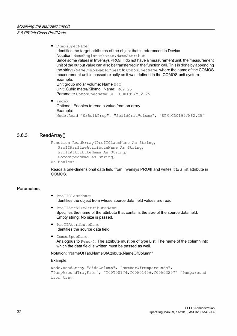
3.6.3 ReadArray() Function ReadArray(ProIIClassName As String, ProIIArrSizeAttributeName As String, ProIIAttributeName As String, ComosSpecName As String) As BooleanReads a one-dimensional data field from Invensys PRO/II and writes it to a list attribute in COMOS.
Parameters● ProIIClassName:
Identifies the object from whose source data field values are read.
● ProIIArrSizeAttributeName:Specifies the name of the attribute that contains the size of the source data field. Empty string: No size is passed.
● ProIIAttributeName:Identifies the source data field.
● ComosSpecName:Analogous to Read(). The attribute must be of type List. The name of the column into which the data field is written must be passed as well.
3.6.4 ReadArrayToFewSpecs() Function ReadArrayToFewSpecs (ProIIClassName As String, ProIIArrSizeAttributeName As String, ProIIAttributeName As String, ComosSpecNames As String) As BooleanReads a one-dimensional data field from Invensys PRO/II and writes it to multiple attributes of the COMOS object that is managed by the ProIINode instance.
ParametersProIIClassName, ProIIArrSizeAttributeName und ProIIAttributeName:
As ReadArray().
ComosSpecNames:
Contains the names of the target attributes. They are passed in a string, separated by commas.
This function is used if values are stored in one data field in Invensys PRO/II and distributed over two data fields in COMOS.
3.6.5 ReadSI() Function ReadSI (ProIIClassName As String, ProIIAttributeName As String, [index As Integer = -999]) As DoubleReturns the value of an attribute from Invensys PRO/II as a numeric value. The function is called if you need the value within control flow structures, for example.
There are differences between Invensys PRO/II and COMOS with regard to the use of SI standardization. If there is a difference, the COMOS SI standardization is used as a basis. This means that the value is converted from the unit specified by the Invensys PRO/II standardization into the unit specified by the COMOS standardization.
ParametersSee also chapter Read() (Page 31).
Modifying the standard import3.6 PRO/II:Class ProIINode
3.6.6 GetComosSpecArray() Function GetComosSpecArray(ComosSpecNames As String,ComosSpecCount As Integer) As String()Help method.
Parameters● ComosSpecNames As String:
Comma-separated list of COMOS attributes.
● ComosSpecCount As Integer:Number of attributes that are passed in ComosSpecNames.Return value:String Array: Each field contains one of the attribute names that were passed in ComosSpecNames.
3.6.7 Functions that are used internally ProIINode owns additional functions that are only called internally and which have no application in the modification of the import.
"ReadMainComp()"Function ReadMainComp (ProIIClassName As String, ProIIAttributeName As String, ComosSpecName As String, [index As Integer = -999]) As BooleanReads a value from Invensys PRO/II and writes it to a subobject (component) of the CompCalc engineering object.
ParametersSee also chapter Read() (Page 31).
"ReadStreamComp()"Function ReadStreamComp (ProIIClassName As String, ProIIAttributeName As String, ComosSpecName As String, [index As Integer = -999]) As BooleanWrites data to a component link below a material stream. The component link is created, if it does not already exist. The objects created are based on the base object "@30 > M21 > A50 > A10 > A20 > A30 > A30 Components - Simulation object".
Modifying the standard import3.6 PRO/II:Class ProIINode
"ReadTempStream()"Function ReadTempStream(StreamID As String)It is possible to create virtual streams in Invensys PRO/II. A call to this function imports a virtual stream to COMOS.
First, the stream is created in COMOS below the calling object. Then, the data is imported in the same way as for a normal material stream.
"ReadTrayStreams()"Sub ReadTrayStreams()If this function is called at a column, an object with name prefix "Tray" is created below the column for each tray.
The objects created are instances of the base object "@30 > M21 > A50 > A10 > A20 > A30 > A20 Column tray - simulation object".
3.7 HYSYS: Class HYSYSNode
You can modify the first two import steps using the HYSYSNode class from the "HYSYSImport.dll" file.
BackgroundAn instance of HYSYSNode is created for each simulation object during the import operation. This instance is a temporary object that serves as a link between COMOS (the target object) and AspenTech HYSYS (the source object) and is only available during the import operation.
The import functions defined in the "Script" tab are called for each simulation object in the first two import steps and the HYSYSNode instance created for this simulation object is transferred as a parameter. See also chapter Overview of the topic "Modifying the standard import" (Page 11).
The import calls can be extended via the functions and variables of the HYSYSNode instance and the standard import function modified for the first two import steps.
In the "HYSYSImport.dll" file, there is also the HYSYSImport class.
This class is initialized via the OnClick() script of the "BUTTON1 Start Import" button of the AspenTech HYSYS import object. See also chapter Buttons for import objects (Page 11). Subsequently, the following function of the HYSYSImport instance is called in the script:
Sub Import(ByVal objSimCase As IComosBaseObject)This function starts the import operation. A reference to the AspenTech HYSYS import object is transferred as a parameter.
Modifying the standard import3.7 HYSYS: Class HYSYSNode
"HeatExchangerCurve"During the import of HCurves, the Properties are calculated via PH-Flash.
"SurfaceTension"The surface tension is imported. This information only exists in HYSYS as a Bulk Property meaning that it is only output for the overall flow but not for the individual phases.
3.7.2 HYSYSClass() Function HYSYSClass() As StringReads the HYSYS class name from HYSYSObject.
3.7.3 LiquidPhase1() Function LiquidPhase1() As ObjectCall at simulation material streams.
If HYSYSObject involves a stream, this function returns the LiquidPhase1 object of the HYSYS stream. The phase data can be read from the object.
3.7.4 LiquidPhase2()Function LiquidPhase2() As ObjectSee also chapter LiquidPhase1() (Page 37).
3.7.5 Read() Function Read(strSpecName As String, hyAttribute As Variant, [strHYSYSUnit As String], [strParam As String])Reads a single value from HYSYS and writes it to an attribute of the COMOS object managed by HYSYSNode.
● strSpecName:Target attribute
● hyAttribute:The HYSYS object.
Modifying the standard import3.7 HYSYS: Class HYSYSNode
● strHYSYSUnit:Optional The value that is passed here is set as SI unit. Then the value is converted into the unit that was set for the target attribute.If a number is passed: The value of the HYSYS object is multiplied by this factor.Blank: The default unit for this HYSYS object type is determined and used.
● strParam:OptionalIf the target attribute is a list. The index for setting the XValue.
3.7.6 ReadPhase Sub ReadPhase(strchapter As String, hyFluidPhase As Object)Call at simulation stream objects. Writes phase tabs to streams.
hyFluidPhase:
For example, by calling LiquidPhase1().
3.7.7 VaporPhase() Function VapourPhase() As ObjectSee also chapter LiquidPhase1() (Page 37).
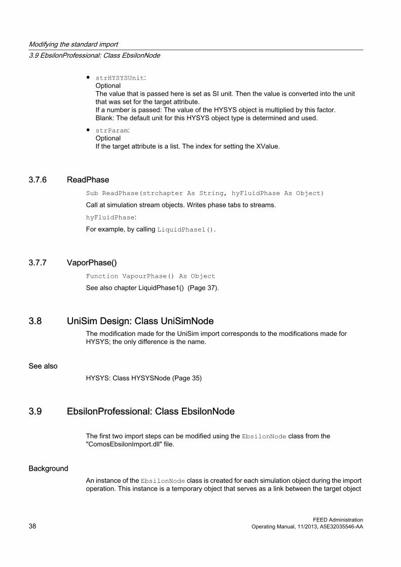
3.8 UniSim Design: Class UniSimNodeThe modification made for the UniSim import corresponds to the modifications made for HYSYS; the only difference is the name.
See alsoHYSYS: Class HYSYSNode (Page 35)
3.9 EbsilonProfessional: Class EbsilonNode
The first two import steps can be modified using the EbsilonNode class from the "ComosEbsilonImport.dll" file.
BackgroundAn instance of the EbsilonNode class is created for each simulation object during the import operation. This instance is a temporary object that serves as a link between the target object
Modifying the standard import3.9 EbsilonProfessional: Class EbsilonNode
in COMOS and the source object in EbsilonProfessional and is only available during the import operation.
The import functions defined in the "Script" tab are called for each simulation object during the first two import steps. The instance of EbsilonNode that was created for the simulation object is transferred as a parameter. See also chapter Overview of the topic "Modifying the standard import" (Page 11).
The import calls can be extended by means of the functions and variables of the EbsilonNode instance, thus modifying the standard import function for the first two import steps.
In the "ComosEbsilonImport.dll" file, there is also the EBSILONImport class. This class is initialized via the OnClick() script of the "BUTTON1 Start Import" button of the Ebsilon import object. See also chapter Buttons for import objects (Page 11). Next, the following function of the EBSILONImport instance is called in the script:
Sub Import(ByVal objSimCase As IComosBaseObject)This function starts the import operation. A reference to the Ebsilon import object is transferred as a parameter.
Result of the callThe simulation objects are created below objSimCase and an instance of EbsilonNode is created for each simulation object.
3.9.1 Properties
"ComosObject"ComosDevice As IComosDDeviceThe target object in COMOS.
"ebsObject"EbsilonObject As ebsOpen.ObjectThe source object.
3.9.2 GetEbsKind()Function GetEbsKind () As StringReads the Ebsilon class name from ebsObject.
3.9.3 Read()
ScriptFunction Read
Modifying the standard import3.9 EbsilonProfessional: Class EbsilonNode
(ByVal ebsAttribute As String, Optional ByVal strSpecName As String, Optional ByVal SpecListIndex As Long = -1, Optional ByVal strParam As String = "") As StringReads a single value from EbsilonProfessional and writes it to an attribute of the COMOS object managed by EbsilonNode.
Script DescriptionebsAttribute Target attribute: If no name is specified, the value is simply returned. Writing
does not take place.SpecListIndex Optional: If the target attribute is a list attribute.strParam Optional: Only strvalue is processed as a possible transfer value. If this is
set, the .StringValue rather than the Value of the Ebsilon attribute is returned.
strSpecName Optional: Target attribute: If no name is specified, the value is simply returned. Writing does not take place.
3.9.4 ReadNumeric()
ScriptFunction ReadNumeric (ByVal ebsAttribute As String, Optional ByVal strSpecName As String, Optional ByVal SpecListIndex As Long = -1, Optional ByVal strParam As String = "") As Double
Script DescriptionebsAttribute Name of the attribute to be read outstrSpecName Optional: Target attribute: If no name is specified, the value is simply
returned. Writing does not take place.SpecListIndex Optional: If the target attribute is a list attribute.strParam Optional: Not currently used.
3.10 ChemCad: Class ChemCad Node
The first two import steps can be modified using the ChemCadNode class from the "ComosChemCadImport.dll" file.
Modifying the standard import3.10 ChemCad: Class ChemCad Node
BackgroundAn instance of the ChemCadNode class is created for each simulation object during the import operation. This instance is a temporary object that serves as a link between the target object in COMOS and the source object from ChemCad and is only available during the import operation.
The import functions defined in the "Script" tab are called for each simulation object during the first two import steps. The instance of ChemCadNode that was created for this simulation object is transferred as a parameter. See also chapter Overview of the topic "Modifying the standard import" (Page 11).
The import calls can be extended by means of the functions and variables of the ChemCadNode instance, thus modifying the standard import function for the first two import steps.
In the "ComosChemCadImport.dll" file, there is also the CHEMCADImport class. This class is initialized via the OnClick() script of the "BU001 Start import" button of the Chemstation ChemCad import object. See also chapter Buttons for import objects (Page 11). Next, the following function of the CHEMCADImport instance is called in the script:Sub Import(ByVal objSimCase As IComosBaseObject)This function starts the import operation. A reference to the CHEMCADImport object is transferred as a parameter.
Result of the callThe simulation objects are created below objSimCase and an instance of ChemCadNode is created for each simulation object.
3.10.1 Properties
"ComosDevice"ComosDevice As IComosDDeviceThe target object in COMOS.
"StreamComponents"Components As ObjectReference to the components of the active FluidPackage from Chemstations ChemCad.
"NodeType"NodeType As eNodeTypeVariable that identifies the ChemCad type and is only used internally.
"SpecLog"SpecLog As IComosDSpecification
Modifying the standard import3.10 ChemCad: Class ChemCad Node
Reference to the "ND0122" attribute at the import object, to which the log text is written. This property is used to control the output during the import operation.
"UnitOp Type"Enumeration for the type of Unit Operation / Equipment
3.10.2 GetChemCadClass()Function GetChemCadClass () As StringReturns the CHEMCAD class name of the object.
3.10.3 ReadNumeric()
ScriptFunction ReadNumeric (ByVal ccAttribute As String, ByVal strSpecName As String, ByVal Unit As String, Optional ByVal SpecListIndex As Long = -1, Optional ByVal StreamID As Integer = -1, Optional ByVal strParam As String = "") As DoubleReads a single value from Chemstations ChemCad and writes it to an attribute of the COMOS object managed by ChemCadNode.
Script DescriptionccAttribute Source attribute in Chemstations ChemCadstrSpecName Target attribute in COMOSUnit Target unit in unit conversionSpecListIndex Optional: Only if the target attribute is a list.
The index for setting the XValue.StreamID Optional: Required for reading out values for components below a
stream.strParam Optional: Not currently used.
3.10.4 ReadEquilibriumReactionPar()
ScriptFunction ReadEquilibriumReactionPar (ByVal ccAttribute As String,
Modifying the standard import3.10 ChemCad: Class ChemCad Node
ByVal strSpecName As String, ByVal Unit As String, ByVal ReactionNo As Integer, ByVal CompID As Integer, Optional ByVal SpecListIndex As Long = -1) As DoubleSpecial case for equilibrium reactions. See also chapter ReadNumeric() (Page 42).
3.10.5 ReadStreamComponentsFunction ReadStreamComponents() As LongAccesses components at a stream one by one and executes the script for components for each one.
3.10.6 FillTrayStreamListFunction FillTrayStreamList()Reads the input and output streams of a column and writes them, together with their corresponding tray numbers, to the SImObject of the column.
3.11 Default settings for the simultaneous import of multiple filesA link to the PFD template to be used for the PFD equipment and PFD process streams (import steps 3 and 4) must be set up in the import options for the "Batch Import Control Center" object.
A link to a suitable PFD template is already set by default. You can view this default setting and link a different PFD template, if required.
Procedure1. In the "Base objects" tab in the Navigator, open the node "@10 > A10 > A10 > A10 > A30
> A40 Simulation import objects".
2. Open the properties of the "Batch Import Control Center" object.
3. Go to the "Attributes > Import options" tab.The link to the PFD template is displayed in the "Link to PFD template" field.
4. If required, click the "..." button and select a different PFD template in the "Link to PFD template" field.
5. Save your entries once you have made the changes.
Modifying the standard import3.11 Default settings for the simultaneous import of multiple files
3.12 Setting margins for automatic placing of equipment on reports To keep space free for a logo or other design elements on PFDs, you can set margins for the automatic placing of equipment on reports for the standard import. This is entirely independent of the type of simulator used.
These settings are used when placing equipment automatically. You can find more information on this topic in the "FEED Operation" manual, keyword "Placing equipment on a preset PFD".
Procedure1. You can set margins for the automatic placing of equipment on reports in the following ways:
– To make a change to a report in individual cases, select a report "Process flow diagram" in the "Units" tab.
– To make basic settings for a certain type of report, create a copy of the corresponding base object in the "Base objects" tab and make your changes.You can find additional information on this topic in the "COMOS Platform Administration" manual, keyword "Copying objects".
2. Open the properties of the required report.
3. Go to the "Attributes > Document options" tab.
4. Deactivate the "Standard border placement" option.
5. Make your entries for the coordinate system of the report in the "Left and right border" and "Upper and lower border" fields.
6. Save your entries.
3.13 Excluding certain simulation types from the importAfter activating the "Create dummy objects" option in the "Import options" tab in the properties of the import document, all of the simulation objects present are imported as dummy simulation objects with an import of unknown simulation objects.
As the administrator, you can also define simulation types that are not to be imported as exception classes.
Procedure1. In the "Base objects" tab in the Navigator, open the node "@30 > M21 > A50 > A10 > A20
> A10 > A40 Dummy simulation object".
2. Open the properties of the "Dummy simulation object" and go to the "Attributes > Import data" tab.
Modifying the standard import3.13 Excluding certain simulation types from the import
3. Enter the simulation types that are not to be imported in the field bearing the name of the simulator concerned. To enter more than one simulation type in a field, you must enter the types separated by a comma ",".
4. Confirm your entries.
3.14 Adapting an HTRI import/exportThe HTRI import is controlled via script by the "ComosHTRIImport.dll" file. For this reason, check the settings in this file.
Procedure1. Click the "Extra > Object debugger" command in the menu bar.
2. Click the "Help" button.
3. In the "Script: components, declarations" window, click in the "Declaration" tab.There is a list at the very top. You can also fill this list from Microsoft Explorer using drag&drop.
4. Select the desired DLL file in Microsoft Explorer; in this case:"<COMOS>\OCX\Import\ComosHTRIImport.dll" or "<COMOS>\Bin\OCX\Import\ComosHTRIImport.dll"
Modifying the standard import3.14 Adapting an HTRI import/export
Creating and grouping pure components under the "Pure components" folder 4
You can make settings defining how new pure components are created and/or grouped under the "Pure components" folder in the "Units" tab in the Navigator.
Corresponding menu commands are available to the user in the context menu of the "Pure components" folder or in the context menu of a component group located beneath it, e.g. "Solids", "Fluids", or "Gases".
Example1. Call the example project to illustrate this.
2. Select the "Solids" component group.
3. Navigate to the base object via the context menu and view the pure components in the component group.
4. Use the existing structure as a guide and then make your entries in the engineering project.
You can find more information on this topic in the "FEED Operation" manual, keyword "Creating components".
Tips for base data administrators 55.1 Tips on process units
To ensure that the process units in the block flow diagram are automatically added to the "Process units" folder of the process, the following conditions must be fulfilled:
● In the base project, activate the "Subelements" option in the "System" tab for the subnode of the "@30 > M00 > A20 > A10 > A10 > A30 Process" base object.Note that the base object whose "Subelements" mode is activated is the base object under which the block flow diagram is located.
● "Process units" folder: Activate the "Subelements" creation mode here too.
● For the subfolders of the "@30 > M00 > A20 > A10 > A10 > A30 Process" base object, select the "Unit" class and "Category" subclass in the "System" tab.
● The process unit must be an element of the "Process unit" folder.
● In the Options script block of the report template of the block flow diagram the term SortNewObjectsInCategories = True must be available.
Base object for flags: "@30 > M21 > A50 > A10 > A30 > A40 Boundary stream flag T, p, M/t"
5.3 Checking the links of the equipment attributesThe links between the maximum and minimum temperature and pressure as well as between the design data on the "Design data" tab and the data of the connected stream can be controlled as follows:
Script function GetDisplayValue() of the attributes "Y00A01915", "Y00A01892", "Y00A01923" and "Y00A01902".
Path in the database: "@30 > M21 > A50 > A10 > A30 Simulation objects"
The base objects for the simulation objects generated in the first import step are located under this object.
StructureThe following structure objects are located under the node on the first level:
● Equipment simulation objects (Page 52)
● Stream simulation objects (Page 54)
● Simulation subobjects (Page 55)
● Simulation import objects (Page 57)
The actual simulation objects are located underneath the structure objects.
6.1.1 Properties of the simulation objects
"Import data" tabThe simulation objects that are located below the structure objects all have the "Import data" tab. The tab has the following attributes:
Attribute DescriptionNames of the simulators
This field specifies the class of simulator to which the base object is assigned. The simulation object is assigned to the object from the source file on the basis of the value entered here. The attributes can contain multiple designators, separated from one another by commas and without blank spaces. The spelling of the designator must be identical to the one used in the simulator.
"Relative path" Specifies where the associated PFD object is to be created in the second import step. During an import from a simulator, the PFD objects are always created as specified at the import object, in the "Pure components", Equipment", and "Process streams" fields in the "Import options" tab. See also chapter Simulation import objects (Page 57).
"PFD object" Is automatically set during the second import step. References the PFD object that is created in the second import step for this simulation object.
"CDevice" Determines which base object is to be used to create a PFD object for the simulation object. See also chapter CompCalc simulation object (Page 54).
The "@30 > M21 > A50 > A10 > A30 > A10 Equipment - Simulation objects" node adds additional attributes to the "Import data" tab inherited from "@30 > M21 > A50 > A10 > A30 Simulation objects". See also chapter Equipment simulation objects (Page 52).
"System data" tabThe "Object class" attribute stores object classes. The attribute is not evaluated during the import operation. You can use it in scripts for internal purposes; for example, when making a search for all objects of a particular class.
Edit mode of the attributesThe following applies to the attributes of the "Simulation objects" node:
As a rule, attributes whose values are imported from the simulator have the edit mode "Values in XML (Limited functionality)". This edit mode is not absolutely essential, but it should be selected so that the data can be imported more quickly.
Functionality of the attributeThis mode restricts the functionality of the attribute (for example, linking is no longer possible).
You can find additional information on this topic in the "COMOS Platform Administration" manual, keyword "Values in XML (Limited functionality)".
ScriptsEach object below the "Simulation objects" node defines functions in the "Script" tab that determine what is to be done with this object during the first and second import steps.
In the database, a command is available in the functions to start the standard import. This call should not be deleted. However, the functions can be extended with commands of their own and the standard import operation is thus modified.
The call of the standard import may only be deleted if the standard import function is to be disabled completely for this object and an import operation of your own is to be defined in the "Script" tab by means of the scripts.
"Import data" tabThe BLC objects extend the "Import data" tab with additional attributes from the attributes catalog. The following attributes are filled with data from the simulator in the first import step:
Field Description"X" X-coordinate of the placement point from the flowchart of the simulator. Remains blank
during a Aspen Plus import."Y" Y-coordinate of the placement point from the flowchart of the simulator. Remains blank
during an Aspen Plus import.
The following attributes are relevant for the second import step:
At the base data end, prepare default values that can then be modified as required in the planning view:
Control element Description"Connectors" table List that allocates the virtual connectors imported from the simulator to the
connectors of the PFD object, and also allocates the connectors of the PFD object to those of the connected PFD process stream.● Columns "PFD connector" and "Simulator connector": Assignment
between the connectors of the PFD object and the connectors from the simulator. Used if an assembly reference is set. You must consider that some of the connectors are no longer available for the process streams because they have already been connected to objects from the assembly. If the object from the simulator has more connectors than had been prepared at the PFD object, dynamic connectors for the missing connectors are created in the second import step.
● Columns "Connected with" and "By connector": Determines for each connector of the PFD object with which process stream and via which connector it is connected. Automatically set in the first import set and can be modified manually prior to the second import step.
"PFD assembly" field The attribute is evaluated in the second import step. Reference to a folder from the "@Template" branch of the base project, below which multiple copy templates were prepared. Based on the data that accompanied the simulation object, COMOS checks which of the assemblies prepared in the database in this folder is the appropriate assembly, creates the objects of this assembly, and connects them as defined in the assembly. The attribute is evaluated in the second import step. If an assembly of your own was prepared, the second import step must be modified in such a way that this assembly is also included in the checking.
"No sim object collapse" option
Prevents the "PFD Assembly" attribute from being evaluated. No assembly is created, only the equipment object that is referenced via the "Base object" attribute. The attribute can be activated in the engineering view.
Other tabsWhich other tabs are available and which attributes they contain depends on the equipment object in question.
In the engineering view, the attributes of the tabs are filled via the first import step. The assignment between the source attribute and the COMOS attribute is hardcoded in the relevant import DLLs. However, this assignment can still be modified by means of scripts. See also chapter Modifying the standard import (Page 11).
6.1.3 Stream simulation objects
Path in the database: "@30 > M21 > A50 > A10 > A30 > A20 Stream - Simulation objects"
Structure of the node:● CompCalc simulation object (Page 54)
"CompCalc - Simulation object" is the base object for the simulation object below which the pure components are collected in the engineering view in the first import step.
Special feature in comparison with the other simulation objects:
● "Import data" tab, "CDevice" attribute:The simulation pure components are created below the CompCalc simulation object in the first import step. The "@10 > A10 > A10 > A10 > A40 > A50 Components" base object is always used as the base object for the simulation pure components. See also chapter Pure components (Page 65).However, the CompCalc simulation object can also be used outside the automated interface import. Since no PFD counterpart is required for the CompCalc simulation object in the second import step, you enter which base object is to be used for the simulation pure components here. For that reason the attribute must be editable, even if a manual change is not taken into consideration during an interface import operation.
● "Import data" tab, "PFD object" attribute:Since no PFD object is created for the simulation object in the second import step, the attribute remains blank.
6.1.3.2 Material stream simulation objectPath to the database: "@30 > M21 > A50 > A10 > A30 > A20 > A30 Material stream - Simulation object"
This is the base object of the simulation objects for material streams that are created in the first import step.
Only the design case-specific data of the process streams is imported from the simulator. In COMOS, this data is stored in material stream objects. The components, that is, the components of the design case, are located below each material stream.
Importing the main caseMultiple PFD objects are created during the second import step for each material stream simulation object:
● PFD process stream
● PFD material streams for the imported design case as well as for the default design cases
Importing a subcaseOnly a new PFD material stream is created below an existing process stream.
Properties
Property Description"Name" The PFD process stream that was created in the
second import step takes over the name of the simulation stream. The name is evaluated during the import of a subcase. If another material stream with the same name was already imported, it is not necessary to create a new process stream in the second step.
"Import data" tab, "PFD object" attribute The attribute is evaluated during the import of a subcase. If a simulation stream of the same name exists already, the "new" material stream is created below the process stream referenced at the older simulation stream in this attribute. See also chapter Properties of the simulation objects (Page 51).
"System data" tab, "Object class" attribute Value: Material stream simulation"General stream data" tab, "Equipment from simulation" attribute
Is set automatically during an import. Contains the name of the equipment from the simulator with which the stream is connected. The attributes are evaluated in the fourth step during an import from PRO/II and HYSYS, in order to determine the PFD equipment to which the stream is connected.
"General stream data" tab,"Stream from simulation" attribute
6.1.4 Simulation subobjects
Path in the database: "@30 > M21 > A50 > A10 > A30 > A30 Simulation subobjects"
These are simulation objects that are created below other simulation objects. For example:
Simulation object for heating curve data. In the second import step the PFD heat exchanger gets references to the simulation heating curves. The data of the heating curves is used for calculating the heat exchanger via an HTRI export and afterwards is imported to COMOS.
You can find more information on this topic in the "FEED Operation" manual, keyword "HTRI import/export". See also chapter Heat exchanger (Page 61).
This is the base object for the component simulation objects that are created below the simulation objects for material streams in the first import step. It is not possible to set another base object through customizing.
The object has the following properties:
Properties Description"Name" In the engineering view: The same as the name of the component
from the simulator. The "name" of the simulation component is used in the second import step to assign a pure component to the associated PFD component. See also chapter Components (Page 64).
"Description" PRO/II import: The description of the PRO/II stream object can be imported.
"Import data" tab, "CDevice" attribute
● In order to convert the simulation components into PFD components, the "@10 > A10 > A10 > A10 > A40 > A50 Component" base object is always used within the system for an interface import operation. Reason: PFD components should be created in the second import step, to which a PFD pure component is assigned automatically. The component objects are needed for this purpose.
● However, the "Components - simulation object" can also be used outside the automated interface import. In that case it is necessary to manually input which base object is to be used in the conversion. For that reason the attribute must be editable, even if a manual change is not taken into consideration during an interface import operation.
"PD Component reference data" tab The attributes of the tab are inherited from the attributes catalog.
Simulation components of the column traysIf the import options are set accordingly, trays are created underneath the column in the first import step, and simulation components underneath the trays.
These components are likewise based on the "MAPSIM" object. However, they are not converted into PFD components in the second import step.
Aspen: Empty simulation componentsSimulation components with empty values are not imported when importing from Aspen.
Column trays are only imported if the import objects have been configured accordingly.
The simulation trays are created automatically with the following name: "Tray<counter>".
Properties
Tab Description"System data" The "Object class" attribute contains the
"Simulation tray" value.Other tabs These tabs are filled during the import operation. The values of these
tabs can also be applied by the equipment case of a PFD tray after the second import step. For this, the equipment case gets a reference to this simulation tray. See also chapter Tray layout (general) (equipment case) (Page 63).
Function of "Aspen XML simulation import" and "ProMax XML simulation import"The objects define the user interface via which the import takes place. They make the import functionality available.
On the engineering side, create the object in the "Simulation data, process unit" folder under a SIMCASE. To do this, select the "New > <Simulation import>" command in the context menu.
Following attributes must be configured in the base data:
Field Description"Import file" field This is set on the engineering side.
Here, the user selects the file to be imported. A link to the source file is always created. The file should have a defined structure. You can find more information on this topic in the "FEED Operation" manual, keyword "Import from Aspen Plus and ProMax".
"Design case" field Enter the main case here. "DESIGN" is specified as the main case in the database. Enter another value here if necessary. The field must not remain blank. If the attribute is blank in the planning view, no PFD objects can be created.
"Pointers" control group:
Field Description"Import to process unit" This is set on the engineering side.
An entry is required here if the PFD objects in step 2 are to be created below a process unit other than that of the direct owner structure.
Buttons Description"Start Import" button This button has an OnClick() script that initiates the relevant
import step of the standard import. Do not delete this script. If necessary, you can expand the OnClick() script to include your own calls. See also chapter Buttons for import objects (Page 11).
● "Log text": Entries regarding possible errors or incorrect configurations are output here during the import operation.The attribute can only store a limited number of characters. Because of that, an additional TXT or XML file is created in the "Temp" user directory, containing all log messages, i.e. also the ones that could not be stored in the log attribute. The full log information is an important tool for the administrator when configuring the import.
"Import options" tabThe attributes of the tab are preconfigured in the database with the values given below, but they can also be set on the engineering side.
● "Path relative to the simulation data folder" control group:Specifies precisely where below the process unit the PFD objects that are created in step 2 are to be located. The path is relative to the "Simulation data process" folder. The entry "../" corresponds to a higher hierarchy level.
Attribute Description"Relative path to pure component" field
Determines where pure components are created
"Relative path to equipment" field
Determines where the equipment is created
"Relative path to process stream" field
Determines where the process streams are created
● "Aspen import options"/"ProMax import options" control group
– "Columns/trays/stages" list: Determines whether or not the data of the objects located below the column is to be imported as well. See also chapter PRO/II simulation import process (Page 72).
6.1.5.2 Simulation case process unitPath in the database: "@10 > A10 > A10 > A10 > A30 > A40 > A50 Simulation case process unit"
Only of importance if the alternative planning structure is used.
You can find more information on this topic in the "FEED Operation" manual, keyword "Required engineering structure".
6.2 PFD objects
Distinctions within the term "PFD objects"Only objects for equipment and process streams are placed on a PFD diagram. Equipment and process streams are PFD objects in the narrower sense.
The other base objects that are introduced in the following chapters are only to be regarded as PFD objects in the broader sense.
They are created in the second import step and fulfill the function of data containers. The data stored in them relate to the equipment or process streams, which is why they are also created underneath these objects. The sole exception are pure components. They are managed separately in the planning view, but likewise have a relation to the PFD objects through their implementation pointers to the components.
6.2.1 Equipment
Path in the database: "@30 > M21 > A50 > A10 > A20 Equipment"
The base objects of the PFD equipment are located in this branch. During the import from a simulator, the PFD equipment is created in the second import step.
6.2.1.1 General properties of equipment
SymbolsA symbol for the "PFD" drawing type must be available in the "Symbols" tab.
ElementsMost of the objects own the following elements in the "Elements" tab:
● This is where you determine the active design case. All equipment case objects that are located below the equipment are offered.The attributes of the "Technical data" and "PD > Process data" tabs are linked to the equipment case selected here, and their values are taken from the active equipment case.
● The OnChange() and FillCombolist() scripts prepared in the database at the attribute must not be deleted.
● In the simulation import, the attributes of the equipment case are linked in turn with those of the simulation object.
"System data" tabThis is, for example, where the attributes for the object class and for changing the unit system are located.
The tabs are inherited from the tabs catalog.
6.2.1.2 ColumnPath in the database: "@30 > M21 > A50 > A10 > A20 > A20 > A20 Column"
This is the base object for a PFD column.
"Elements" tabPath in the database: "@30 > M21 > A50 > A10 > A20 > A80 > A20 Column section"
A structure, underneath which the various column sections are prepared. The section is created manually.
If the column is created via an assembly, then a section is created automatically underneath the column, and a tray is created underneath that section.
Attribute Description"Heating Curve 1" A maximum of three simulation heating curves (hot and cold)."Heating Curve 2""Heating Curve 3"
The references to the simulation objects of the heating curves are set in the second import step. Via an HTRI export, the data of the heating curves is used in order to calculate the heat exchanger. When it is reimported to COMOS, this information is written directly to the heat exchanger PFD.
Base objects for a trayWhen a column is created via one of the assemblies prepared in the database, a column section is created automatically below the column, and a tray is created below the column section. Additional trays are created using the "New" command in the context menu.
The PFD tray assumes the values of the following tabs from its active equipment case:
A structure, underneath which the various column sections are prepared.
Simulation importIf the simulation column has a reference to one of the assemblies prepared in the database, the section is automatically created together with the column via the assembly, and a tray is created below the section.
6.2.2 Equipment design cases
Path in the database: "@30 > M21 > A50 > A10 > A10 Equipment design cases"
Containers that store the design case-specific data of the PFD equipment.
This branch is structured similar to "@30 > M21 > A50 > A10 > A20 Equipment". A number of attribute values are passed from the active equipment case to its PFD equipment.
6.2.3 ComponentsPath in the database: "@30 > M21 > A50 > A10 > A40 > A50 Component"
Base object for PFD componentsThe PFD components are created in the second import step as counterparts for the simulation components. It is not possible to use a different base object for the PFD components in the interface import.
The PFD components are created below the design cases of process streams. Two references are set when they are created for the purposes of better data management:
● To their simulation component, from which the values of the "Identification data" tab are inherited
● To their pure component, from which the values of the "Pure component data" tab are inherited
COMOS proceeds as follows to assign a pure component to the PFD component:
COMOS takes the name of the referenced simulation component and checks whether there is already a pure component in the "Pure components" folder to which the following applies:
The name specified for a pure component in the "Substance name from simulation" attribute in the "System data" tab is the same as the name of the simulation component.
If no matching pure component is found, the component is not created.
Properties
Property Description"Name" Automatically generated via the text mask at the base object"Description" The same as the description of the assigned pure component"Implementation" The pure component assigned during creation is set automatically
"Component data" tab● "Material from simulation" attribute: Link to the underlying simulation component. The
reference is entered automatically.
● The remaining attributes of the tab are linked with the simulation component that is referenced under the "Material from simulation" attribute; the values are assumed automatically from there.See also chapter Process streams (Page 66).
"Actual component data" tab● "Component" attribute: Link to the assigned PFD pure component. The reference is entered
automatically.
● The other attributes of the tab are linked to the pure component that is referenced under "Component"; its values are assumed automatically from there.
"System data" tabThis is where the attributes for the object class and for changing the unit system are located. The tabs are inherited from the tabs catalog.
6.2.4 Pure componentsPath in the database: "@30 > M21 > A50 > A10 > A40 > A60 Pure components"
The base objects for pure components are located in this folder.
Base object for pure componentsPath in the database: "@30 > M21 > A50 > A10 > A40 > A60 > A10 Pure component"
On the engineering side, pure components are used in the second import step, when a simulation pure component is to be converted into a PFD pure component for the first time. COMOS reads out the name of the simulation pure component and checks whether there is a pure component underneath the "@30 > M21 > A50 > A10 > A40 > A60 > Pure components" folder to which the following applies:
One of the names entered in "Name from simulation" in the "Identification data" tab is identical to the name of the simulation pure component.
● If such a pure component is found, it is created in the engineering view in the "Pure components" folder underneath the process.
● If no such pure component is found, COMOS uses the ""@30 > M21 > A50 > A10 > A40 > A60 > A10 > Pure component" object.
6.2.5 Design casesPath in the database: "@30 > M21 > A50 > A10 > A40 > A80 Design case"
This is the PFD counterpart to the simulation design case of process streams.
It stores the design case-specific data for its process stream and is created automatically during the second import step:
● Importing the main case:The design case for the main case is created together with its process stream and the default design cases.
● Importing a subcase:Only the PFD design case for the imported subcase is created below an existing process stream.
Property Description"Name" Receives the name of the design case entered at the import object"Class" Position"Subclass" Material stream"Functional classification"
"P3D8 Position/Pipe"
"System data" tabThe "Stream from simulation" attribute is set automatically during the second import step.
See alsoProcess streams (Page 66)
6.2.6 Process streamsPath in the database: "@30 > M21 > A50 > A10 > A40 > A90 Process stream"
Base object for PFD process streamsThese are created automatically in the second import step:
● Importing the main case:A process stream is created for each design case from the simulation below the import object. The process stream obtains the "Name" of the simulation design case.PRO/II: If the PRO/II description of the simulation design case was imported, the process stream also assumes the description; otherwise, it assumes the description of the base object.The PFD design case for the main case and additional design cases for the default design cases are created below the process stream.
● Importing a subcase:A new process stream is only created if a simulation design case with this name is imported for the first time.
"System" tab
Property Description"Name" The same name as the simulation material stream"Class" "Point""Subclass" "Pipe"
"Elements" tabThe following elements must be created:
● An element for a material stream with the following properties:
– Option "Virtual" equals "N times".
– Base object reference to "@10 > A10 > A10 > A10 > A40 > A80 Design case"This element is required to create the main case and/or the subcases.
● If default design cases are required: At least one element for a default design case.Three design cases are preconfigured in the database: "DESIGN", "MIN", and "MAX".Properties:
– "Virtual" option: OffThe material streams are created automatically together with the process stream.
– Base object reference to "@10 > A10 > A10 > A10 > A40 > A80 Design case"
● An element for segmentation of the process stream must exist:
– "Name": SEG
– "Class": Element"Subclass": Pipe
– Option "Virtual" equals "N times"
"Connectors" tabTwo connectors of type "FEED" must be prepared here:
● Input: "CI1"
● Output: "CO1".
"Attributes > Current stream data" tabContains the design case-specific data of the process stream. The data is taken from the design cases of the process stream using attribute links.
"Material stream list" tabIf a base object has the "Position" class and the "Pipe" subclass, the "Material stream list" tab is automatically made available in the "Configuration" tab of the base object.
The base object for process streams is configured in the database in such a way that the tab is displayed on the engineering side.
The tab is based on a query and reads important data from all design cases that are located below the process stream.
The currently active design case is shown in bold in the list.
Column Description"Name" Unique string, also the same as the ASPEN name"Description" The visible text. "Value 1" The nested name of the COMOS attribute.
6.4.2 "Aspen units for domain DELTA-T"
Area of applicationName of an attributes group in ASPEN: "DELTA-T".
COMOS checks during the import whether there is an additional table below the "Aspen units" standard table with a name matching one of the attribute groups to be imported.
If this is the case, preference is given to the more specific table that is located below. This allows you to make different COMOS attribute assignments for individual ASPEN groups.
Node"Standard tables > Y40 > M21 > A10 > Y40M21N00002 Aspen units for domain DELTA-T"
ExampleIn COMOS, temperatures and temperature differences are managed in separate attributes, both of which have the "C" unit. This is why there is a "C" entry in the "Aspen units" standard table which accesses the "J40.AA100" attribute. "J40.AA100" is responsible for the temperature. The "DELTA-T" standard table also contains a "C" entry which accesses the "J40.AA100" attribute. "J40.AA100" is responsible for the temperature.
6.4.3 "TEMA letter 1-3"
Area of applicationTEMA is part of the "heat exchangers" topic.
Node● "Standard tables > @40 > Y00 > A10 > B30 > Y00N00285 TEMA letter 1"
● "Standard tables > @40 > Y00 > A10 > B30 > Y00N00286 TEMA letter 2"
● "Standard tables > @40 > Y00 > A10 > B30 > Y00N00287 TEMA letter 3"
See alsoPRO/II simulation import process (Page 72)
6.4.6 System: "Graphical representation"
"Colors" standard tableSpecifies the colors of PFD/P&ID objects.
Column Description"Name" Unique string, also controls the order of the list in the user selection. "Description" The visible text. "Value 1" The LOGOCAD color code.
Special feature:
The value "- 1" means that the user set a Windows color manually. The Windows color code is stored internally. In this case, the color that was assigned to the object on the interactive report applies. This value corresponds to the LOGOCAD color code.
"Logocad line types" standard tableThese are the line types that are available in PFD/P&ID drawing types.
Column Description"Name" Unique string, also controls the order of the list in the user selection. "Description" The visible text. "Value 1" This code defines what pattern the line type has.
Base object for the import document of levels 1 and 2 of the PRO/II interface. This base object defines the user interface through which the import operation is controlled and provides the import functionality.
The document with which the import operation is executed in the engineering view must be of document type "PRO/II". Then it automatically has a link to this base object and thus to the required import functionality.
The document must be created below the "Simulation data, process unit" folder.
Requirements for document type mapping (PRO/II)A base object with the following properties is prepared in the database under the "@99 > A30 > M00 > A20 Document type mapping" node:
● The name is the same as the file extension of the Invensys PRO/II simulator
● The object has a base object reference to "@20 > A60 > A10 > A50 > A70 PRO/II Simulation import process".
You can find more information on this topic in the "FEED Operation" manual, keyword "Creating an import document".
"Import data" tabThis tab controls the individual import steps.
It functions in the same way as the tab of the Aspen Plus import object. See also chapter Simulation import objects (Page 57).
The tab differs in the following ways from the Aspen Plus import object:
Base data reference6.5 Base objects for import documents
● There is no attribute referenced for the import file.
● "Place PFD equipment"Not available in the Aspen Plus import.
● "Place PFD streams"Analogous to the Aspen Plus import object, but with its own OnClick() script.
● "Design case":In contrast to the Aspen Plus import, there is no separate base object for the import of subcases in an Invensys PRO/II import. Instead, the Invensys PRO/II import objects are nested within each other.
– Import object of level 1 (main case):Enter the main case. The main case and the default design cases are created.
– Import object of level 2 (subcase)The subcase is created.
– "DESIGN" is preconfigured as the main case in the database.
– This attribute should not be left blank, since otherwise the PFD objects cannot be created.
● No attribute for the number of the used Invensys PRO/II version.
In contrast to the Aspen Plus import object, the PRO/II import object has the following attribute:
● "Import into document":If the PFD objects are to be placed on another PFD in steps 3 and 4 than on the PFD that had automatically been created below the process unit. Can be set by the user at the engineering end (optional).
"Import options" tabThe attributes of the tab are preconfigured in the database with the values given below, but they can also be set on the engineering side.
● "Path relative to the simulation data import (SIMD)" control group:Specifies below which objects the PFD objects that were created in step 2 are to be located. See also chapter Simulation import objects (Page 57).
● "Object-specific import options" control group:
– "Columns/trays/stages":Specifies whether or not the data of the objects located below the column is to be imported as well. "Not imported": Only the data of the column itself are imported; the data of the associated trays and components are not imported."Trays/stages without composition": The data of the column and trays is imported. The data of the components is not imported."Trays/stages and composition": The data of the column, trays, and components is imported.
– "Stream/tray/stage composition":Specifies which attributes on the "Component reference data" tab are imported for the simulation components.Does not exist: COMOS calculates the values.
Base data reference6.5 Base objects for import documents
"Attributes > System data" tab"Object class" attribute: Stored using standard table
This attribute is not evaluated during the import operation. It can be used by the user in scripts for internal purposes, for example when searching for all objects of a particular class.
Base object for the import document of levels 1 and 2 of the HYSYS interface. This base object defines the user interface through which the import operation is controlled and provides the import functionality.
The document of type "HSC" must be created below the "SIMD" folder.
Requirements for document type mapping (HYSIS)A base object with a name identical to the file extension of the HYSYS simulator is prepared in the database under the "@99 > A30 > M00 > A20 Document type mapping" node.
You can find more information on this topic in the "FEED Operation" manual, keyword "Creating an import document".
"Import data" tabThis tab controls the individual import steps. It functions in the same way as the tab of the Invensys PRO/II import object. See also chapter PRO/II simulation import process (Page 72).
"Import options" tabIt functions in the same way as the tab of the PRO/II import object, but it has fewer attributes.
See also chapter PRO/II simulation import process (Page 72).
Base data reference6.5 Base objects for import documents
"Links to base objects" control groupThe links are set as standard in the database. If you use a different standard structure, select the corresponding base objects from the standard structure here.
Field Description"Base object node for simulation objects" Mandatory information
During simulation imports, the simulation objects underneath this node are used.
"Base object node for stream objects" Mandatory informationDuring simulation imports, the stream objects underneath this node are used.
"Base object for pure component" Mandatory informationDuring simulation imports, this object is used for the imported pure components.
"Links to queries for the process/material stream tabs" control group
Field DescriptionBase object for the query on the 'Material stream list' tab
The results of the query are displayed on the "Material stream list" tab at process streams or their design cases.
Base object for the query on the 'Components' tab The results of the query are displayed on the "Components" tab at process streams or their design cases.
"Link to process for the FEED structure" control group
Field Description"Base object node for the process" Determines which base object for the process is