16-1 CHAPTER 16 COMPOSITES PROBLEM SOLUTIONS Large-Particle Composites 16.1 The elastic modulus versus volume percent of WC is shown below, on which is included both upper and lower bound curves; these curves were generated using Equations 16.1 and 16.2, respectively, as well as the moduli of elasticity for cobalt and WC given in the problem statement. Excerpts from this work may be reproduced by instructors for distribution on a not-for-profit basis for testing or instructional purposes only to students enrolled in courses for which the textbook has been adopted. Any other reproduction or translation of this work beyond that permitted by Sections 107 or 108 of the 1976 United States Copyright Act without the permission of the copyright owner is unlawful.
Transcript
16-1
CHAPTER 16
COMPOSITES
PROBLEM SOLUTIONS
Large-Particle Composites
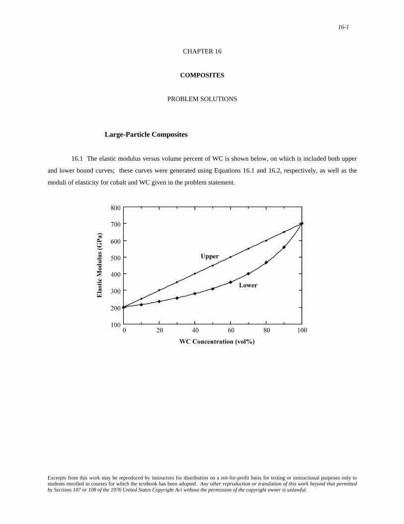
16.1 The elastic modulus versus volume percent of WC is shown below, on which is included both upper
and lower bound curves; these curves were generated using Equations 16.1 and 16.2, respectively, as well as the
moduli of elasticity for cobalt and WC given in the problem statement.
Excerpts from this work may be reproduced by instructors for distribution on a not-for-profit basis for testing or instructional purposes only to students enrolled in courses for which the textbook has been adopted. Any other reproduction or translation of this work beyond that permitted by Sections 107 or 108 of the 1976 United States Copyright Act without the permission of the copyright owner is unlawful.
16-2
16.2 This problem asks for the maximum and minimum thermal conductivity values for a TiC-Ni cermet. Using a modified form of Equation 16.1 the maximum thermal conductivity kmax is calculated as
Using a modified form of Equation 16.2, the minimum thermal conductivity kmin will be
kmin =
kNikTiCVNikTiC + VTiCkNi
= (67 W /m- K)(27 W /m- K)
(0.10)(27 W /m- K) + (0.90)(67 W /m- K)
= 28.7 W/m-K
Excerpts from this work may be reproduced by instructors for distribution on a not-for-profit basis for testing or instructional purposes only to students enrolled in courses for which the textbook has been adopted. Any other reproduction or translation of this work beyond that permitted by Sections 107 or 108 of the 1976 United States Copyright Act without the permission of the copyright owner is unlawful.
16-3
16.3 Given the elastic moduli and specific gravities for copper and tungsten we are asked to estimate the
upper limit for specific stiffness when the volume fractions of tungsten and copper are 0.70 and 0.30, respectively.
There are two approaches that may be applied to solve this problem. The first is to estimate both the upper limits of elastic modulus [Ec(u)] and specific gravity (ρc) for the composite, using expressions of the form of Equation 16.1,
and then take their ratio. Using this approach
Ec(u) = ECuVCu + EWVW
= (110 GPa)(0.30) + (407 GPa)(0.70)
= 318 GPa
And
ρc = ρCuVCu + ρWVW
= (8.9)(0.30) + (19.3)(0.70) = 16.18
Therefore
Specific Stiffness =
Ec (u)ρc
=318 GPa
16.18= 19.65 GPa
With the alternate approach, the specific stiffness is calculated, again employing a modification of
Equation 16.1, but using the specific stiffness-volume fraction product for both metals, as follows:
Specific Stiffness =
ECuρCu
VCu + EWρW
VW
= 110 GPa
8.9(0.30) + 407 GPa
19.3(0.70) = 18.47 GPa
Excerpts from this work may be reproduced by instructors for distribution on a not-for-profit basis for testing or instructional purposes only to students enrolled in courses for which the textbook has been adopted. Any other reproduction or translation of this work beyond that permitted by Sections 107 or 108 of the 1976 United States Copyright Act without the permission of the copyright owner is unlawful.
16-4
16.4 (a) Concrete consists of an aggregate of particles that are bonded together by a cement.
(b) Three limitations of concrete are: (1) it is a relatively weak and brittle material; (2) it experiences
relatively large thermal expansions (contractions) with changes in temperature; and (3) it may crack when exposed
to freeze-thaw cycles.
(c) Three reinforcement strengthening techniques are: (1) reinforcement with steel wires, rods, etc.; (2)
reinforcement with fine fibers of a high modulus material; and (3) introduction of residual compressive stresses by
prestressing or posttensioning.
Excerpts from this work may be reproduced by instructors for distribution on a not-for-profit basis for testing or instructional purposes only to students enrolled in courses for which the textbook has been adopted. Any other reproduction or translation of this work beyond that permitted by Sections 107 or 108 of the 1976 United States Copyright Act without the permission of the copyright owner is unlawful.
16-5
Dispersion-Strengthened Composites
16.5 The similarity between precipitation hardening and dispersion strengthening is the strengthening
mechanism--i.e., the precipitates/particles effectively hinder dislocation motion.
The two differences are: (1) the hardening/strengthening effect is not retained at elevated temperatures for
precipitation hardening--however, it is retained for dispersion strengthening; and (2) the strength is developed by a
heat treatment for precipitation hardening--such is not the case for dispersion strengthening.
Excerpts from this work may be reproduced by instructors for distribution on a not-for-profit basis for testing or instructional purposes only to students enrolled in courses for which the textbook has been adopted. Any other reproduction or translation of this work beyond that permitted by Sections 107 or 108 of the 1976 United States Copyright Act without the permission of the copyright owner is unlawful.
16-6
Influence of Fiber Length
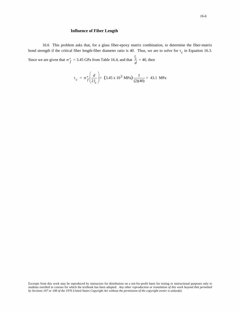
16.6 This problem asks that, for a glass fiber-epoxy matrix combination, to determine the fiber-matrix bond strength if the critical fiber length-fiber diameter ratio is 40. Thus, we are to solve for τc in Equation 16.3.
Since we are given that = 3.45 GPa from Table 16.4, and that σ f
∗
lcd
= 40, then
τc = σ f
∗ d2 lc
⎛
⎝ ⎜ ⎜
⎞
⎠ ⎟ ⎟ = (3.45 x 10³ MPa) 1
(2)(40)= 43.1 MPa
Excerpts from this work may be reproduced by instructors for distribution on a not-for-profit basis for testing or instructional purposes only to students enrolled in courses for which the textbook has been adopted. Any other reproduction or translation of this work beyond that permitted by Sections 107 or 108 of the 1976 United States Copyright Act without the permission of the copyright owner is unlawful.
16-7
16.7 (a) The plot of reinforcement efficiency versus fiber length is given below.
(b) This portion of the problem asks for the length required for a 0.90 efficiency of reinforcement.
Solving for l from the given expression
l = 2x
1 − η
Or, when x = 1.25 mm (0.05 in.) and η = 0.90, then
l = (2)(1.25 mm)
1 − 0.90= 25 mm (1.0 in.)
Excerpts from this work may be reproduced by instructors for distribution on a not-for-profit basis for testing or instructional purposes only to students enrolled in courses for which the textbook has been adopted. Any other reproduction or translation of this work beyond that permitted by Sections 107 or 108 of the 1976 United States Copyright Act without the permission of the copyright owner is unlawful.
16-8
Influence of Fiber Orientation and Concentration
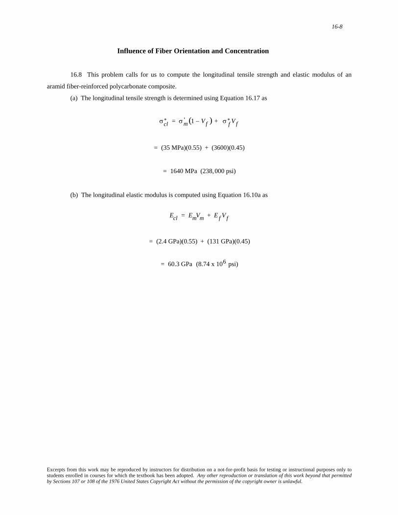
16.8 This problem calls for us to compute the longitudinal tensile strength and elastic modulus of an
aramid fiber-reinforced polycarbonate composite.
(a) The longitudinal tensile strength is determined using Equation 16.17 as
σcl
∗ = σm' (1 − Vf ) + σ f∗ Vf
= (35 MPa)(0.55) + (3600)(0.45)
= 1640 MPa (238,000 psi)
(b) The longitudinal elastic modulus is computed using Equation 16.10a as
Ecl = EmVm + E f Vf
= (2.4 GPa)(0.55) + (131 GPa)(0.45)
= 60.3 GPa (8.74 x 10⁶ psi)
Excerpts from this work may be reproduced by instructors for distribution on a not-for-profit basis for testing or instructional purposes only to students enrolled in courses for which the textbook has been adopted. Any other reproduction or translation of this work beyond that permitted by Sections 107 or 108 of the 1976 United States Copyright Act without the permission of the copyright owner is unlawful.
16-9
16.9 This problem asks for us to determine if it is possible to produce a continuous and oriented aramid
fiber-epoxy matrix composite having longitudinal and transverse moduli of elasticity of 35 GPa and 5.17 GPa,
respectively, given that the modulus of elasticity for the epoxy is 3.4 GPa. Also, from Table 16.4 the value of E for aramid fibers is 131 GPa. The approach to solving this problem is to calculate values of Vf for both longitudinal and
transverse cases using the data and Equations 16.10b and 16.16; if the two Vf values are the same then this
composite is possible. For the longitudinal modulus Ecl (using Equation 16.10b),
Ecl = Em(1 − Vfl) + E f V fl
35 GPa = (3.4 GPa)(1 − Vfl) + (131 GPa)Vfl
Solving this expression for Vfl (i.e., the volume fraction of fibers for the longitudinal case) yields Vfl = 0.248.
Now, repeating this procedure for the transverse modulus Ect (using Equation 16.16)
Ect =
EmE f(1 − Vft)E f + VftEm
5.17 GPa = (3.4 GPa)(131 GPa)
(1 − Vft ) (131 GPa) + Vft (3.4 GPa)
Solving this expression for Vft (i.e., the volume fraction of fibers for the transverse case), leads to Vft = 0.351.
Thus, since Vfl and Vft are not equal, the proposed composite is not possible.
Excerpts from this work may be reproduced by instructors for distribution on a not-for-profit basis for testing or instructional purposes only to students enrolled in courses for which the textbook has been adopted. Any other reproduction or translation of this work beyond that permitted by Sections 107 or 108 of the 1976 United States Copyright Act without the permission of the copyright owner is unlawful.
16-10
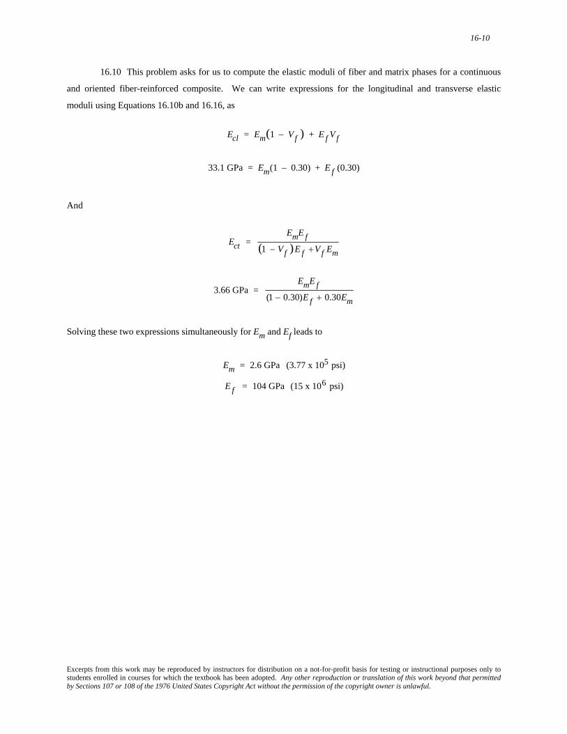
16.10 This problem asks for us to compute the elastic moduli of fiber and matrix phases for a continuous
and oriented fiber-reinforced composite. We can write expressions for the longitudinal and transverse elastic
moduli using Equations 16.10b and 16.16, as
Ecl = Em(1 − Vf ) + E f Vf
33.1 GPa = Em(1 − 0.30) + E f (0.30)
And
Ect =
EmE f(1 − Vf )E f +Vf Em
3.66 GPa =
EmE f(1 − 0.30)E f + 0.30Em
Solving these two expressions simultaneously for Em and Ef leads to
Em = 2.6 GPa (3.77 x 10⁵ psi)
E f = 104 GPa (15 x 106 psi)
Excerpts from this work may be reproduced by instructors for distribution on a not-for-profit basis for testing or instructional purposes only to students enrolled in courses for which the textbook has been adopted. Any other reproduction or translation of this work beyond that permitted by Sections 107 or 108 of the 1976 United States Copyright Act without the permission of the copyright owner is unlawful.
16-11
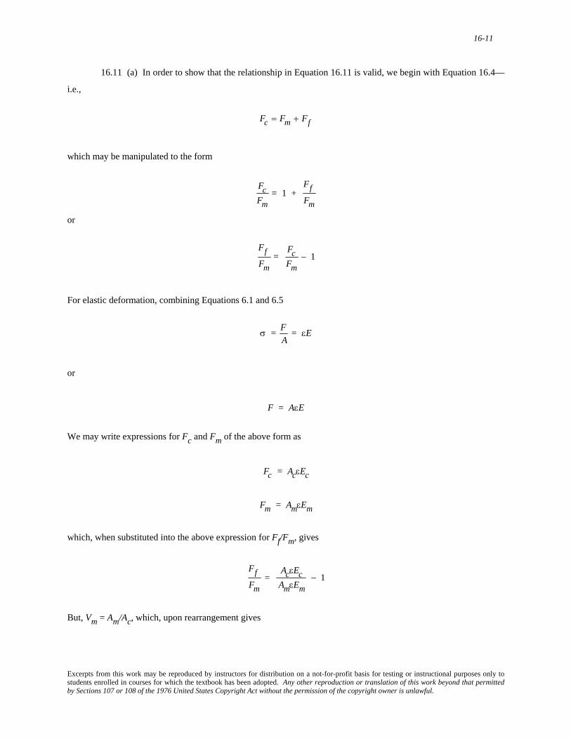
16.11 (a) In order to show that the relationship in Equation 16.11 is valid, we begin with Equation 16.4—
i.e.,
Fc = Fm + Ff
which may be manipulated to the form
FcFm
= 1 + FfFm
or
FfFm
= FcFm
− 1
For elastic deformation, combining Equations 6.1 and 6.5
σ = F
A= εE
or
F = AεE
We may write expressions for Fc and Fm of the above form as
Fc = AcεEc
Fm = AmεEm
which, when substituted into the above expression for Ff/Fm, gives
FfFm
= AcεEcAmεEm
− 1
But, Vm = Am/Ac, which, upon rearrangement gives
Excerpts from this work may be reproduced by instructors for distribution on a not-for-profit basis for testing or instructional purposes only to students enrolled in courses for which the textbook has been adopted. Any other reproduction or translation of this work beyond that permitted by Sections 107 or 108 of the 1976 United States Copyright Act without the permission of the copyright owner is unlawful.
16-12
AcAm
=1
Vm
which, when substituted into the previous expression leads to
FfFm
= Ec
EmVm− 1
Also, from Equation 16.10a, Ec = EmVm + EfVf, which, when substituted for Ec into the previous expression, yields
FfFm
= EmVm + E f Vf
EmVm− 1
=
EmVm + E f Vf − EmVmEmVm
= E f VfEmVm
the desired result. (b) This portion of the problem asks that we establish an expression for Ff/Fc. We determine this ratio in a
similar manner. Now Fc = Ff + Fm (Equation 16.4), or division by Fc leads to
1 =
FfFc
+ FmFc
which, upon rearrangement, gives
FfFc
= 1 −FmFc
Now, substitution of the expressions in part (a) for Fm and Fc that resulted from combining Equations 6.1 and 6.5
results in
FfFc
= 1 −AmεEmAcεEc
= 1 −AmEmAcEc
Since the volume fraction of fibers is equal to Vm = Am/Ac, then the above equation may be written in the form
Excerpts from this work may be reproduced by instructors for distribution on a not-for-profit basis for testing or instructional purposes only to students enrolled in courses for which the textbook has been adopted. Any other reproduction or translation of this work beyond that permitted by Sections 107 or 108 of the 1976 United States Copyright Act without the permission of the copyright owner is unlawful.
16-13
FfFc
= 1 −VmEm
Ec
And, finally substitution of Equation 16.10(a) for Ec into the above equation leads to the desired result as follows:
FfFc
= 1 −VmEm
VmEm + Vf E f
=
VmEm + Vf E f − VmEmVmEm + Vf E f
=
Vf E fVmEm + Vf E f
=
Vf E f(1 − Vf )Em + Vf E f
Excerpts from this work may be reproduced by instructors for distribution on a not-for-profit basis for testing or instructional purposes only to students enrolled in courses for which the textbook has been adopted. Any other reproduction or translation of this work beyond that permitted by Sections 107 or 108 of the 1976 United States Copyright Act without the permission of the copyright owner is unlawful.
16-14
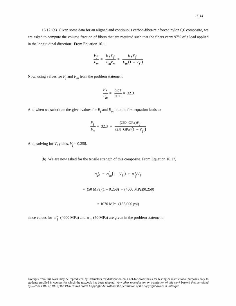
16.12 (a) Given some data for an aligned and continuous carbon-fiber-reinforced nylon 6,6 composite, we
are asked to compute the volume fraction of fibers that are required such that the fibers carry 97% of a load applied
in the longitudinal direction. From Equation 16.11
FfFm
= E f VfEmVm
= E f Vf
Em (1 − Vf )
Now, using values for Ff and Fm from the problem statement
FfFm
= 0.970.03
= 32.3
And when we substitute the given values for Ef and Em into the first equation leads to
FfFm
= 32.3 = (260 GPa)Vf
(2.8 GPa)(1 − Vf )
And, solving for Vf yields, Vf = 0.258.
(b) We are now asked for the tensile strength of this composite. From Equation 16.17,
σcl
∗ = σm' (1 − Vf ) + σ f
∗ Vf
= (50 MPa)(1 − 0.258) + (4000 MPa)(0.258)
= 1070 MPa (155,000 psi)
since values for (4000 MPa) and (50 MPa) are given in the problem statement. σ f
∗ σm'
Excerpts from this work may be reproduced by instructors for distribution on a not-for-profit basis for testing or instructional purposes only to students enrolled in courses for which the textbook has been adopted. Any other reproduction or translation of this work beyond that permitted by Sections 107 or 108 of the 1976 United States Copyright Act without the permission of the copyright owner is unlawful.
16-15
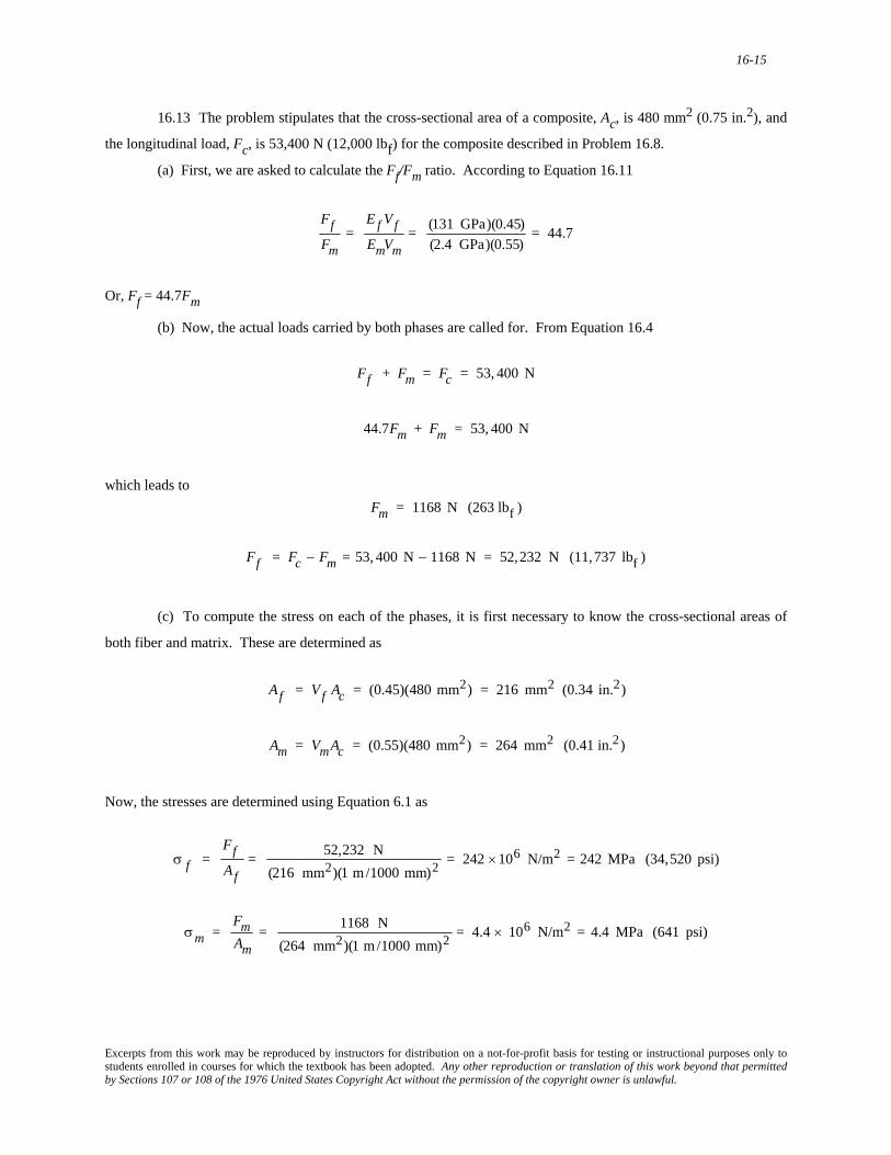
16.13 The problem stipulates that the cross-sectional area of a composite, Ac, is 480 mm2 (0.75 in.2), and
the longitudinal load, Fc, is 53,400 N (12,000 lbf) for the composite described in Problem 16.8.
(a) First, we are asked to calculate the Ff/Fm ratio. According to Equation 16.11
FfFm
= E f VfEmVm
= (131 GPa)(0.45)(2.4 GPa)(0.55)
= 44.7
Or, Ff = 44.7Fm
(b) Now, the actual loads carried by both phases are called for. From Equation 16.4
Ff + Fm = Fc = 53, 400 N
44.7Fm + Fm = 53, 400 N
which leads to
Fm = 1168 N (263 lbf )
Ff = Fc − Fm = 53, 400 N − 1168 N = 52,232 N (11,737 lbf )
(c) To compute the stress on each of the phases, it is first necessary to know the cross-sectional areas of
both fiber and matrix. These are determined as
Af = Vf Ac = (0.45)(480 mm2) = 216 mm2 (0.34 in.2)
Am = VmAc = (0.55)(480 mm2) = 264 mm2 (0.41 in.2)
Now, the stresses are determined using Equation 6.1 as
Excerpts from this work may be reproduced by instructors for distribution on a not-for-profit basis for testing or instructional purposes only to students enrolled in courses for which the textbook has been adopted. Any other reproduction or translation of this work beyond that permitted by Sections 107 or 108 of the 1976 United States Copyright Act without the permission of the copyright owner is unlawful.
16-16
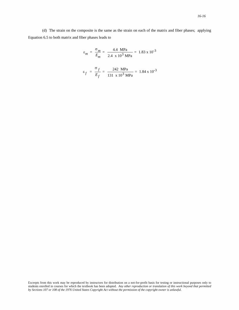
(d) The strain on the composite is the same as the strain on each of the matrix and fiber phases; applying
Equation 6.5 to both matrix and fiber phases leads to
εm =
σmEm
= 4.4 MPa2.4 x 103 MPa
= 1.83 x 10⁻³
ε f =
σ fE f
= 242 MPa131 x 103 MPa
= 1.84 x 10⁻³
Excerpts from this work may be reproduced by instructors for distribution on a not-for-profit basis for testing or instructional purposes only to students enrolled in courses for which the textbook has been adopted. Any other reproduction or translation of this work beyond that permitted by Sections 107 or 108 of the 1976 United States Copyright Act without the permission of the copyright owner is unlawful.
16-17
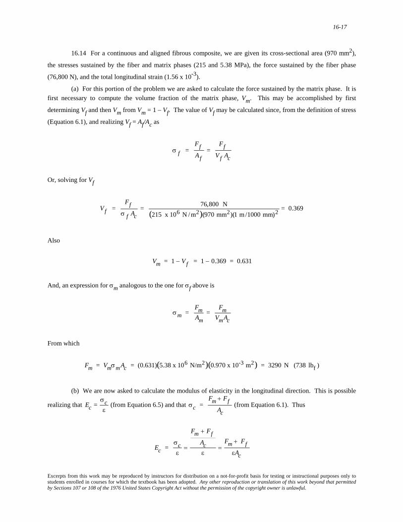
16.14 For a continuous and aligned fibrous composite, we are given its cross-sectional area (970 mm2),
the stresses sustained by the fiber and matrix phases (215 and 5.38 MPa), the force sustained by the fiber phase
(76,800 N), and the total longitudinal strain (1.56 x 10⁻³).
(a) For this portion of the problem we are asked to calculate the force sustained by the matrix phase. It is first necessary to compute the volume fraction of the matrix phase, Vm. This may be accomplished by first
determining Vf and then Vm from Vm = 1 – Vf. The value of Vf may be calculated since, from the definition of stress
(Equation 6.1), and realizing Vf = Af/Ac as
σ f =
FfAf
= Ff
V f Ac
Or, solving for Vf
V f =
Ffσ f Ac
= 76,800 N(215 x 106 N /m2)(970 mm2)(1 m/1000 mm)2 = 0.369
Also
Vm = 1 − Vf = 1 − 0.369 = 0.631
And, an expression for σm analogous to the one for σf above is
σm =
FmAm
= Fm
VmAc
From which
Fm = VmσmAc = (0.631)(5.38 x 10⁶ N/m2)(0.970 x 10-3 m2) = 3290 N (738 lbf )
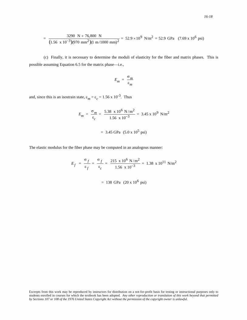
(b) We are now asked to calculate the modulus of elasticity in the longitudinal direction. This is possible
realizing that Ec =
σcε
(from Equation 6.5) and that σc =
Fm + FfAc
(from Equation 6.1). Thus
Ec =
σcε
=
Fm + FfAcε
=Fm + Ff
εAc
Excerpts from this work may be reproduced by instructors for distribution on a not-for-profit basis for testing or instructional purposes only to students enrolled in courses for which the textbook has been adopted. Any other reproduction or translation of this work beyond that permitted by Sections 107 or 108 of the 1976 United States Copyright Act without the permission of the copyright owner is unlawful.
16-18
= 3290 N + 76,800 N
(1.56 x 10⁻³)(970 mm2)(1 m/1000 mm)2 = 52.9 ×10⁹ N/m2 = 52.9 GPa (7.69 x 10⁶ psi)
(c) Finally, it is necessary to determine the moduli of elasticity for the fiber and matrix phases. This is
possible assuming Equation 6.5 for the matrix phase—i.e.,
Em =
σmεm
and, since this is an isostrain state, εm = εc = 1.56 x 10⁻³. Thus
Em =
σmεc
= 5.38 x 10⁶ N /m2
1.56 x 10−3 = 3.45 x 10⁹ N/m2
= 3.45 GPa (5.0 x 10⁵ psi)
The elastic modulus for the fiber phase may be computed in an analogous manner:
E f =
σ fε f
= σ fεc
= 215 x 106 N /m2
1.56 x 10−3 = 1.38 x 10¹¹ N/m2
= 138 GPa (20 x 106 psi)
Excerpts from this work may be reproduced by instructors for distribution on a not-for-profit basis for testing or instructional purposes only to students enrolled in courses for which the textbook has been adopted. Any other reproduction or translation of this work beyond that permitted by Sections 107 or 108 of the 1976 United States Copyright Act without the permission of the copyright owner is unlawful.
16-19
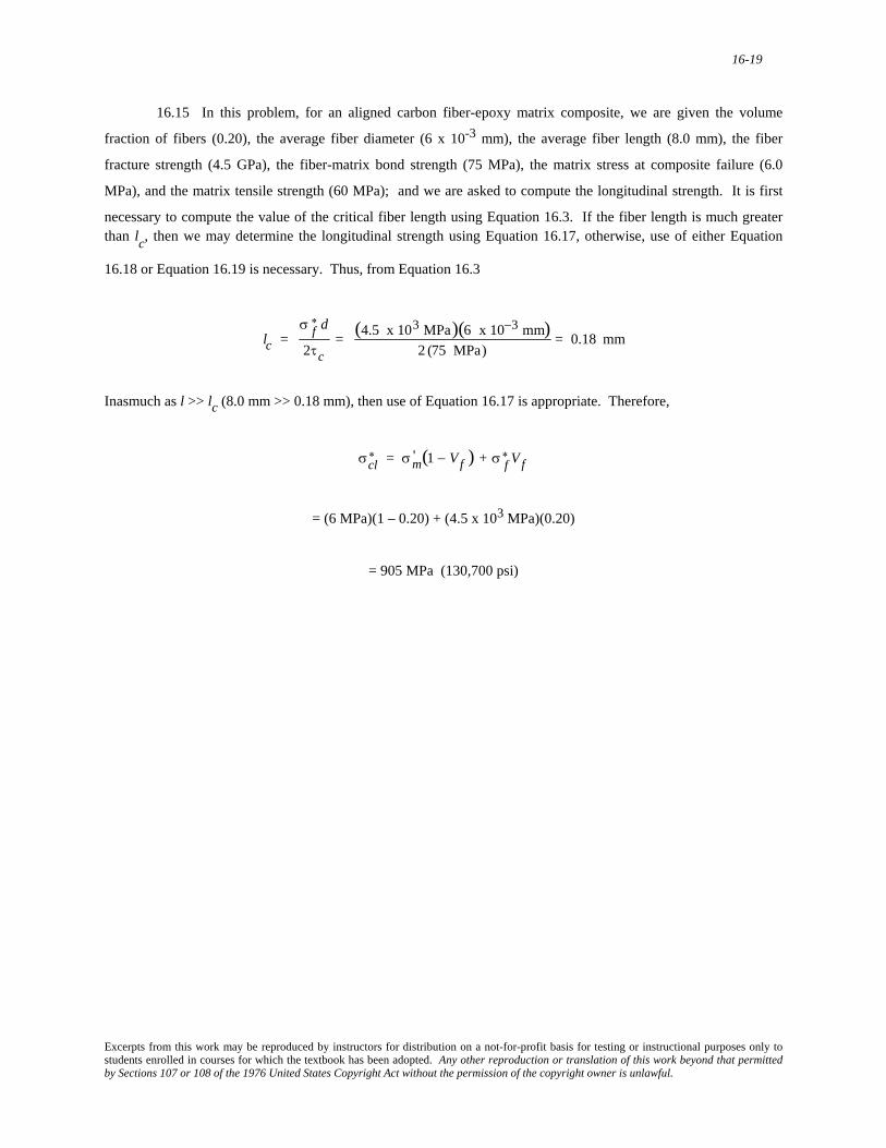
16.15 In this problem, for an aligned carbon fiber-epoxy matrix composite, we are given the volume
fraction of fibers (0.20), the average fiber diameter (6 x 10⁻³ mm), the average fiber length (8.0 mm), the fiber
fracture strength (4.5 GPa), the fiber-matrix bond strength (75 MPa), the matrix stress at composite failure (6.0
MPa), and the matrix tensile strength (60 MPa); and we are asked to compute the longitudinal strength. It is first
necessary to compute the value of the critical fiber length using Equation 16.3. If the fiber length is much greater than lc, then we may determine the longitudinal strength using Equation 16.17, otherwise, use of either Equation
16.18 or Equation 16.19 is necessary. Thus, from Equation 16.3
lc =
σ f∗ d
2τc= (4.5 x 10³ MPa)(6 x 10⁻³ mm)
2 (75 MPa)= 0.18 mm
Inasmuch as l >> lc (8.0 mm >> 0.18 mm), then use of Equation 16.17 is appropriate. Therefore,
σcl
∗ = σm' (1 − Vf ) + σ f∗ Vf
= (6 MPa)(1 – 0.20) + (4.5 x 10³ MPa)(0.20)
= 905 MPa (130,700 psi)
Excerpts from this work may be reproduced by instructors for distribution on a not-for-profit basis for testing or instructional purposes only to students enrolled in courses for which the textbook has been adopted. Any other reproduction or translation of this work beyond that permitted by Sections 107 or 108 of the 1976 United States Copyright Act without the permission of the copyright owner is unlawful.
16-20
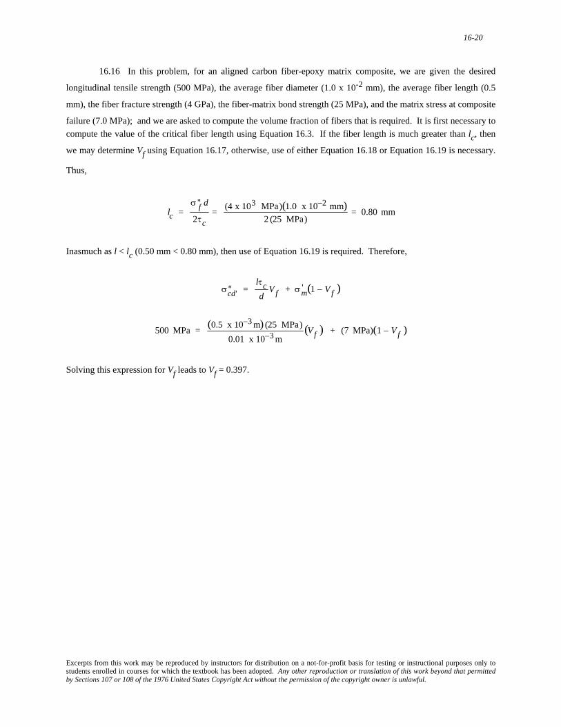
16.16 In this problem, for an aligned carbon fiber-epoxy matrix composite, we are given the desired
longitudinal tensile strength (500 MPa), the average fiber diameter (1.0 x 10⁻² mm), the average fiber length (0.5
mm), the fiber fracture strength (4 GPa), the fiber-matrix bond strength (25 MPa), and the matrix stress at composite
failure (7.0 MPa); and we are asked to compute the volume fraction of fibers that is required. It is first necessary to compute the value of the critical fiber length using Equation 16.3. If the fiber length is much greater than lc, then
we may determine Vf using Equation 16.17, otherwise, use of either Equation 16.18 or Equation 16.19 is necessary.
Thus,
lc =
σ f∗ d
2τc= (4 x 10³ MPa)(1.0 x 10⁻² mm)
2 (25 MPa)= 0.80 mm
Inasmuch as l < lc (0.50 mm < 0.80 mm), then use of Equation 16.19 is required. Therefore,
σcd'
∗ = lτcd
Vf + σm' (1 − Vf )
500 MPa = (0.5 x 10⁻³ m) (25 MPa)
0.01 x 10⁻³ m(Vf ) + (7 MPa)(1 − Vf )
Solving this expression for Vf leads to Vf = 0.397.
Excerpts from this work may be reproduced by instructors for distribution on a not-for-profit basis for testing or instructional purposes only to students enrolled in courses for which the textbook has been adopted. Any other reproduction or translation of this work beyond that permitted by Sections 107 or 108 of the 1976 United States Copyright Act without the permission of the copyright owner is unlawful.
16-21
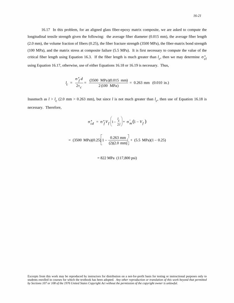
16.17 In this problem, for an aligned glass fiber-epoxy matrix composite, we are asked to compute the
longitudinal tensile strength given the following: the average fiber diameter (0.015 mm), the average fiber length
(2.0 mm), the volume fraction of fibers (0.25), the fiber fracture strength (3500 MPa), the fiber-matrix bond strength
(100 MPa), and the matrix stress at composite failure (5.5 MPa). It is first necessary to compute the value of the
critical fiber length using Equation 16.3. If the fiber length is much greater than lc, then we may determine
using Equation 16.17, otherwise, use of either Equations 16.18 or 16.19 is necessary. Thus, σcl
∗
lc =
σ f∗ d
2τc= (3500 MPa)(0.015 mm)
2 (100 MPa)= 0.263 mm (0.010 in.)
Inasmuch as l > lc (2.0 mm > 0.263 mm), but since l is not much greater than lc, then use of Equation 16.18 is
necessary. Therefore,
σcd
∗ = σ f∗ Vf 1 −
lc2 l
⎛
⎝ ⎜
⎞
⎠ ⎟ + σm' (1 − Vf )
= (3500 MPa)(0.25) 1 −
0.263 mm(2)(2.0 mm)
⎡
⎣ ⎢
⎤
⎦ ⎥ + (5.5 MPa)(1 − 0.25)
= 822 MPa (117,800 psi)
Excerpts from this work may be reproduced by instructors for distribution on a not-for-profit basis for testing or instructional purposes only to students enrolled in courses for which the textbook has been adopted. Any other reproduction or translation of this work beyond that permitted by Sections 107 or 108 of the 1976 United States Copyright Act without the permission of the copyright owner is unlawful.
16-22
16.18 (a) This portion of the problem calls for computation of values of the fiber efficiency parameter.
From Equation 16.20
Ecd = KE f Vf + EmVm
Solving this expression for K yields
K =
Ecd − EmVmE f Vf
= Ecd − Em(1 − Vf )
E f V f
For glass fibers, Ef = 72.5 GPa (Table 16.4); using the data in Table 16.2, and taking an average of the extreme Em
values given, Em = 2.29 GPa (0.333 x 10⁶ psi). And, for Vf = 0.20
K = 5.93 GPa − (2.29 GPa)(1 − 0.2)
(72.5 GPa)(0.2)= 0.283
For Vf = 0.3
K = 8.62 GPa − (2.29 GPa)(1 − 0.3)
(72.5 GPa)(0.3)= 0.323
And, for Vf = 0.4
K = 11.6 GPa − (2.29 GPa)(1 − 0.4)
(72.5 GPa)(0.4)= 0.353
(b) For 50 vol% fibers (Vf = 0.50), we must assume a value for K. Since it is increasing with Vf, let us
estimate it to increase by the same amount as going from 0.3 to 0.4—that is, by a value of 0.03. Therefore, let us
assume a value for K of 0.383. Now, from Equation 16.20
Ecd = KE f Vf + EmVm
= (0.383)(72.5 GPa)(0.5) + (2.29 GPa)(0.5)
= 15.0 GPa (2.18 x 10⁶ psi)
Excerpts from this work may be reproduced by instructors for distribution on a not-for-profit basis for testing or instructional purposes only to students enrolled in courses for which the textbook has been adopted. Any other reproduction or translation of this work beyond that permitted by Sections 107 or 108 of the 1976 United States Copyright Act without the permission of the copyright owner is unlawful.
16-23
The Fiber Phase The Matrix Phase
16.19 (a) For polymer-matrix fiber-reinforced composites, three functions of the polymer-matrix phase
are: (1) to bind the fibers together so that the applied stress is distributed among the fibers; (2) to protect the
surface of the fibers from being damaged; and (3) to separate the fibers and inhibit crack propagation.
(b) The matrix phase must be ductile and is usually relatively soft, whereas the fiber phase must be stiff
and strong.
(c) There must be a strong interfacial bond between fiber and matrix in order to: (1) maximize the stress
transmittance between matrix and fiber phases; and (2) minimize fiber pull-out, and the probability of failure.
Excerpts from this work may be reproduced by instructors for distribution on a not-for-profit basis for testing or instructional purposes only to students enrolled in courses for which the textbook has been adopted. Any other reproduction or translation of this work beyond that permitted by Sections 107 or 108 of the 1976 United States Copyright Act without the permission of the copyright owner is unlawful.
16-24
16.20 (a) The matrix phase is a continuous phase that surrounds the noncontinuous dispersed phase.
(b) In general, the matrix phase is relatively weak, has a low elastic modulus, but is quite ductile. On the
other hand, the fiber phase is normally quite strong, stiff, and brittle.
Excerpts from this work may be reproduced by instructors for distribution on a not-for-profit basis for testing or instructional purposes only to students enrolled in courses for which the textbook has been adopted. Any other reproduction or translation of this work beyond that permitted by Sections 107 or 108 of the 1976 United States Copyright Act without the permission of the copyright owner is unlawful.
16-25
Polymer-Matrix Composites
16.21 (a) This portion of the problem calls for us to calculate the specific longitudinal strengths of glass-
fiber, carbon-fiber, and aramid-fiber reinforced epoxy composites, and then to compare these values with the
specific strengths of several metal alloys. The longitudinal specific strength of the glass-reinforced epoxy material (Vf = 0.60) in Table 16.5 is just
the ratio of the longitudinal tensile strength and specific gravity as
1020 MPa
2.1= 486 MPa
For the carbon-fiber reinforced epoxy
1240 MPa
1.6= 775 MPa
And, for the aramid-fiber reinforced epoxy
1380 MPa
1.4= 986 MPa
Now, for the metal alloys we use data found in Tables B.1 and B.4 in Appendix B (using the density
values from Table B.1 for the specific gravities). For the cold-rolled 7-7PH stainless steel
1380 MPa
7.65= 180 MPa
For the normalized 1040 plain carbon steel, the ratio is
590 MPa
7.85= 75 MPa
For the 7075-T6 aluminum alloy
572 MPa
2.80= 204 MPa
For the C26000 brass (cold worked)
Excerpts from this work may be reproduced by instructors for distribution on a not-for-profit basis for testing or instructional purposes only to students enrolled in courses for which the textbook has been adopted. Any other reproduction or translation of this work beyond that permitted by Sections 107 or 108 of the 1976 United States Copyright Act without the permission of the copyright owner is unlawful.
16-26
525 MPa
8.53= 62 MPa
For the AZ31B (extruded) magnesium alloy
262 MPa
1.77= 148 MPa
For the annealed Ti-5Al-2.5Sn titanium alloy
790 MPa
4.48= 176 MPa
(b) The longitudinal specific modulus is just the longitudinal tensile modulus-specific gravity ratio. For
the glass-fiber reinforced epoxy, this ratio is
45 GPa
2.1= 21.4 GPa
For the carbon-fiber reinforced epoxy
145 GPa
1.6= 90.6 GPa
And, for the aramid-fiber reinforced epoxy
76 GPa
1.4= 54.3 GPa
The specific moduli for the metal alloys (Tables B.1 and B.2) are as follows:
For the cold rolled 17-7PH stainless steel
204 GPa
7.65= 26.7 GPa
For the normalized 1040 plain-carbon steel
207 GPa
7.85= 26.4 GPa
Excerpts from this work may be reproduced by instructors for distribution on a not-for-profit basis for testing or instructional purposes only to students enrolled in courses for which the textbook has been adopted. Any other reproduction or translation of this work beyond that permitted by Sections 107 or 108 of the 1976 United States Copyright Act without the permission of the copyright owner is unlawful.
16-27
For the 7075-T6 aluminum alloy
71 GPa
2.80= 25.4 GPa
For the cold worked C26000 brass
110 GPa
8.53= 12.9 GPa
For the extruded AZ31B magnesium alloy
45 GPa
1.77= 25.4 GPa
For the Ti-5Al-2.5Sn titanium alloy
110 GPa
4.48= 24.6 GPa
Excerpts from this work may be reproduced by instructors for distribution on a not-for-profit basis for testing or instructional purposes only to students enrolled in courses for which the textbook has been adopted. Any other reproduction or translation of this work beyond that permitted by Sections 107 or 108 of the 1976 United States Copyright Act without the permission of the copyright owner is unlawful.
16-28
16.22 (a) The four reasons why glass fibers are most commonly used for reinforcement are listed at the
beginning of Section 16.8 under "Glass Fiber-Reinforced Polymer (GFRP) Composites."
(b) The surface perfection of glass fibers is important because surface flaws or cracks act as points of
stress concentration, which will dramatically reduce the tensile strength of the material.
(c) Care must be taken not to rub or abrade the surface after the fibers are drawn. As a surface protection,
newly drawn fibers are coated with a protective surface film.
Excerpts from this work may be reproduced by instructors for distribution on a not-for-profit basis for testing or instructional purposes only to students enrolled in courses for which the textbook has been adopted. Any other reproduction or translation of this work beyond that permitted by Sections 107 or 108 of the 1976 United States Copyright Act without the permission of the copyright owner is unlawful.
16-29
16.23 "Graphite" is crystalline carbon having the structure shown in Figure 12.17, whereas "carbon" will
consist of some noncrystalline material as well as areas of crystal misalignment.
Excerpts from this work may be reproduced by instructors for distribution on a not-for-profit basis for testing or instructional purposes only to students enrolled in courses for which the textbook has been adopted. Any other reproduction or translation of this work beyond that permitted by Sections 107 or 108 of the 1976 United States Copyright Act without the permission of the copyright owner is unlawful.
16-30
16.24 (a) Reasons why fiberglass-reinforced composites are utilized extensively are: (1) glass fibers are
very inexpensive to produce; (2) these composites have relatively high specific strengths; and (3) they are
chemically inert in a wide variety of environments.
(b) Several limitations of these composites are: (1) care must be exercised in handling the fibers inasmuch
as they are susceptible to surface damage; (2) they are lacking in stiffness in comparison to other fibrous
composites; and (3) they are limited as to maximum temperature use.
Excerpts from this work may be reproduced by instructors for distribution on a not-for-profit basis for testing or instructional purposes only to students enrolled in courses for which the textbook has been adopted. Any other reproduction or translation of this work beyond that permitted by Sections 107 or 108 of the 1976 United States Copyright Act without the permission of the copyright owner is unlawful.
16-31
Hybrid Composites
16.25 (a) A hybrid composite is a composite that is reinforced with two or more different fiber materials
in a single matrix.
(b) Two advantages of hybrid composites are: (1) better overall property combinations, and (2) failure is
not as catastrophic as with single-fiber composites.
Excerpts from this work may be reproduced by instructors for distribution on a not-for-profit basis for testing or instructional purposes only to students enrolled in courses for which the textbook has been adopted. Any other reproduction or translation of this work beyond that permitted by Sections 107 or 108 of the 1976 United States Copyright Act without the permission of the copyright owner is unlawful.
16-32
16.26 (a) For a hybrid composite having all fibers aligned in the same direction
Ecl = EmVm + E f 1Vf 1 + E f 2Vf 2
in which the subscripts f1 and f2 refer to the two types of fibers.
(b) Now we are asked to compute the longitudinal elastic modulus for a glass- and aramid-fiber hybrid
composite. From Table 16.4, the elastic moduli of aramid and glass fibers are, respectively, 131 GPa (19 x 106 psi)
and 72.5 GPa (10.5 x 10⁶ psi). Thus, from the previous expression
Excerpts from this work may be reproduced by instructors for distribution on a not-for-profit basis for testing or instructional purposes only to students enrolled in courses for which the textbook has been adopted. Any other reproduction or translation of this work beyond that permitted by Sections 107 or 108 of the 1976 United States Copyright Act without the permission of the copyright owner is unlawful.
16-33
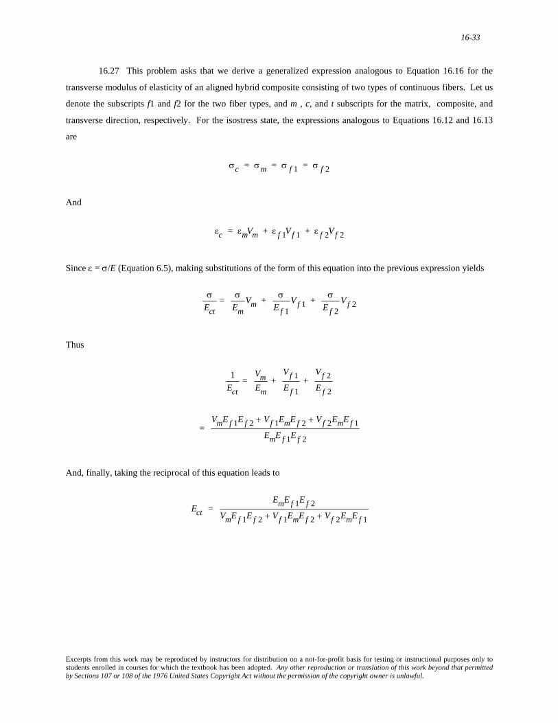
16.27 This problem asks that we derive a generalized expression analogous to Equation 16.16 for the
transverse modulus of elasticity of an aligned hybrid composite consisting of two types of continuous fibers. Let us
denote the subscripts f1 and f2 for the two fiber types, and m , c, and t subscripts for the matrix, composite, and
transverse direction, respectively. For the isostress state, the expressions analogous to Equations 16.12 and 16.13
are
σc = σm = σ f 1 = σ f 2
And
εc = εmVm + ε f 1Vf 1 + ε f 2Vf 2
Since ε = σ/E (Equation 6.5), making substitutions of the form of this equation into the previous expression yields
σEct
= σEm
Vm + σE f 1
Vf 1 + σE f 2
Vf 2
Thus
1Ect
= VmEm
+ Vf 1E f 1
+ Vf 2E f 2
=
VmE f 1E f 2 + Vf 1EmE f 2 + Vf 2EmE f 1EmE f 1E f 2
And, finally, taking the reciprocal of this equation leads to
Ect =
EmE f 1E f 2VmE f 1E f 2 + Vf 1EmE f 2 + Vf 2EmE f 1
Excerpts from this work may be reproduced by instructors for distribution on a not-for-profit basis for testing or instructional purposes only to students enrolled in courses for which the textbook has been adopted. Any other reproduction or translation of this work beyond that permitted by Sections 107 or 108 of the 1976 United States Copyright Act without the permission of the copyright owner is unlawful.
16-34
Processing of Fiber-Reinforced Composites
16.28 Pultrusion, filament winding, and prepreg fabrication processes are described in Section 16.13.
For pultrusion, the advantages are: the process may be automated, production rates are relatively high, a
wide variety of shapes having constant cross-sections are possible, and very long pieces may be produced. The
chief disadvantage is that shapes are limited to those having a constant cross-section.
For filament winding, the advantages are: the process may be automated, a variety of winding patterns are
possible, and a high degree of control over winding uniformity and orientation is afforded. The chief disadvantage
is that the variety of shapes is somewhat limited.
For prepreg production, the advantages are: resin does not need to be added to the prepreg, the lay-up
arrangement relative to the orientation of individual plies is variable, and the lay-up process may be automated. The
chief disadvantages of this technique are that final curing is necessary after fabrication, and thermoset prepregs must
be stored at subambient temperatures to prevent complete curing.
Excerpts from this work may be reproduced by instructors for distribution on a not-for-profit basis for testing or instructional purposes only to students enrolled in courses for which the textbook has been adopted. Any other reproduction or translation of this work beyond that permitted by Sections 107 or 108 of the 1976 United States Copyright Act without the permission of the copyright owner is unlawful.
16-35
Laminar Composites Sandwich Panels
16.29 Laminar composites are a series of sheets or panels, each of which has a preferred high-strength
direction. These sheets are stacked and then cemented together such that the orientation of the high-strength
direction varies from layer to layer.
These composites are constructed in order to have a relatively high strength in virtually all directions
within the plane of the laminate.
Excerpts from this work may be reproduced by instructors for distribution on a not-for-profit basis for testing or instructional purposes only to students enrolled in courses for which the textbook has been adopted. Any other reproduction or translation of this work beyond that permitted by Sections 107 or 108 of the 1976 United States Copyright Act without the permission of the copyright owner is unlawful.
16-36
16.30 (a) Sandwich panels consist of two outer face sheets of a high-strength material that are separated
by a layer of a less-dense and lower-strength core material.
(b) The prime reason for fabricating these composites is to produce structures having high in-plane
strengths, high shear rigidities, and low densities.
(c) The faces function so as to bear the majority of in-plane tensile and compressive stresses. On the other
hand, the core separates and provides continuous support for the faces, and also resists shear deformations
perpendicular to the faces.
Excerpts from this work may be reproduced by instructors for distribution on a not-for-profit basis for testing or instructional purposes only to students enrolled in courses for which the textbook has been adopted. Any other reproduction or translation of this work beyond that permitted by Sections 107 or 108 of the 1976 United States Copyright Act without the permission of the copyright owner is unlawful.
16-37
DESIGN PROBLEMS
16.D1 Inasmuch as there are a number of different sports implements that employ composite materials, no
attempt will be made to provide a complete answer for this question. However, a list of this type of sporting
equipment would include skis and ski poles, fishing rods, vaulting poles, golf clubs, hockey sticks, baseball and
softball bats, surfboards and boats, oars and paddles, bicycle components (frames, wheels, handlebars), canoes, and
tennis and racquetball rackets.
Excerpts from this work may be reproduced by instructors for distribution on a not-for-profit basis for testing or instructional purposes only to students enrolled in courses for which the textbook has been adopted. Any other reproduction or translation of this work beyond that permitted by Sections 107 or 108 of the 1976 United States Copyright Act without the permission of the copyright owner is unlawful.
16-38
Influence of Fiber Orientation and Concentration
16.D2 In order to solve this problem, we want to make longitudinal elastic modulus and tensile strength
computations assuming 40 vol% fibers for all three fiber materials, in order to see which meet the stipulated criteria
[i.e., a minimum elastic modulus of 55 GPa (8 x 10⁶ psi), and a minimum tensile strength of 1200 MPa (175,000 psi)]. Thus, it becomes necessary to use Equations 16.10b and 16.17 with Vm = 0.6 and Vf = 0.4, Em = 3.1 GPa, and
= 69 MPa. σm∗
For glass, Ef = 72.5 GPa and = 3450 MPa. Therefore, σ f
Excerpts from this work may be reproduced by instructors for distribution on a not-for-profit basis for testing or instructional purposes only to students enrolled in courses for which the textbook has been adopted. Any other reproduction or translation of this work beyond that permitted by Sections 107 or 108 of the 1976 United States Copyright Act without the permission of the copyright owner is unlawful.
16-39
which value is also less than the minimum. Therefore, aramid also not a candidate, which means that only the
carbon (PAN standard-modulus) fiber-reinforced epoxy composite meets the minimum criteria.
Excerpts from this work may be reproduced by instructors for distribution on a not-for-profit basis for testing or instructional purposes only to students enrolled in courses for which the textbook has been adopted. Any other reproduction or translation of this work beyond that permitted by Sections 107 or 108 of the 1976 United States Copyright Act without the permission of the copyright owner is unlawful.
16-40
16.D3 This problem asks us to determine whether or not it is possible to produce a continuous and
oriented carbon fiber-reinforced epoxy having a modulus of elasticity of at least 69 GPa in the direction of fiber
alignment, and a maximum specific gravity of 1.40. We will first calculate the minimum volume fraction of fibers
to give the stipulated elastic modulus, and then the maximum volume fraction of fibers possible to yield the
maximum permissible specific gravity; if there is an overlap of these two fiber volume fractions then such a
composite is possible.
With regard to the elastic modulus, from Equation 16.10b
Ecl = Em(1 − Vf ) + E f V f
69 GPa = (2.4 GPa)(1 − Vf ) + (260 GPa)(Vf )
Solving for Vf yields Vf = 0.26. Therefore, Vf > 0.26 to give the minimum desired elastic modulus.
Now, upon consideration of the specific gravity (or density), ρ, we employ the following modified form of
Equation 16.10b
ρc = ρm(1 − Vf ) + ρ f V f
1.40 = 1.25(1 − Vf ) + 1.80(Vf )
And, solving for Vf from this expression gives Vf = 0.27. Therefore, it is necessary for Vf < 0.27 in order to have a
composite specific gravity less than 1.40. Hence, such a composite is possible if 0.26 < Vf < 0.27
Excerpts from this work may be reproduced by instructors for distribution on a not-for-profit basis for testing or instructional purposes only to students enrolled in courses for which the textbook has been adopted. Any other reproduction or translation of this work beyond that permitted by Sections 107 or 108 of the 1976 United States Copyright Act without the permission of the copyright owner is unlawful.
16-41
16.D4 This problem asks us to determine whether or not it is possible to produce a continuous and
oriented glass fiber-reinforced polyester having a tensile strength of at least 1250 MPa in the longitudinal direction,
and a maximum specific gravity of 1.80. We will first calculate the minimum volume fraction of fibers to give the
stipulated tensile strength, and then the maximum volume fraction of fibers possible to yield the maximum
permissible specific gravity; if there is an overlap of these two fiber volume fractions then such a composite is
possible.
With regard to tensile strength, from Equation 16.17
σcl
∗ = σm' (1 − Vf ) + σ f∗ Vf
1250 MPa = (20 MPa)(1 − V f ) + (3500 MPa) (V f )
Solving for Vf yields Vf = 0.353. Therefore, Vf > 0.353 to give the minimum desired tensile strength.
Now, upon consideration of the specific gravity (or density), ρ, we employ the following modified form of
Equation 16.10b:
ρc = ρm(1 − V f ) + ρ f V f
1.80 = 1.35(1 − V f ) + 2.50 (V f )
And, solving for Vf from this expression gives Vf = 0.391. Therefore, it is necessary for Vf < 0.391
in order to have a composite specific gravity less than 1.80. Hence, such a composite is possible if 0.353 < Vf < 0.391.
Excerpts from this work may be reproduced by instructors for distribution on a not-for-profit basis for testing or instructional purposes only to students enrolled in courses for which the textbook has been adopted. Any other reproduction or translation of this work beyond that permitted by Sections 107 or 108 of the 1976 United States Copyright Act without the permission of the copyright owner is unlawful.
16-42
16.D5 In this problem, for an aligned and discontinuous glass fiber-epoxy matrix composite having a
longitudinal tensile strength of 1200 MPa, we are asked to compute the required fiber fracture strength, given the
following: the average fiber diameter (0.015 mm), the average fiber length (5.0 mm), the volume fraction of fibers
(0.35), the fiber-matrix bond strength (80 MPa), and the matrix stress at fiber failure (6.55 MPa).
To begin, since the value of is unknown, calculation of the value of lc in Equation 16.3 is not possible,
and, therefore, we are not able to decide which of Equations 16.18 and 16.19 to use. Thus, it is necessary to
substitute for lc in Equation 16.3 into Equation 16.18, solve for the value of , then, using this value, solve for lc
from Equation 16.3. If l > lc, we use Equation 16.18, otherwise Equation 16.19 must be used. Note: the
parameters in Equations 16.18 and 16.3 are the same. Realizing this, and substituting for lc in Equation 16.3 into
Equation 16.18 leads to
σ f
∗
σ f
∗
σ f
∗
σcd∗ = σ f
∗ Vf 1 −σ f
∗ d
4τcl
⎡
⎣
⎢ ⎢ ⎢
⎤
⎦
⎥ ⎥ ⎥
+ σm' (1 − Vf )
= σ f
∗ Vf − σ f
∗2Vf d
4τcl+ σm' − σm' Vf
This expression is a quadratic equation in which is the unknown. Rearrangement into a more convenient form
leads to σ f
∗
σ f
∗2Vf d
4τcl
⎡
⎣ ⎢ ⎢
⎤
⎦ ⎥ ⎥
− σ f∗ (Vf ) + σcd
∗ − σm' (1 − Vf )⎡ ⎣ ⎢
⎤ ⎦ ⎥ = 0
Or
aσ f
∗2 + bσ f∗ + c = 0
where
a =
Vf d
4τcl
Excerpts from this work may be reproduced by instructors for distribution on a not-for-profit basis for testing or instructional purposes only to students enrolled in courses for which the textbook has been adopted. Any other reproduction or translation of this work beyond that permitted by Sections 107 or 108 of the 1976 United States Copyright Act without the permission of the copyright owner is unlawful.
16-43
= (0.35)(0.015 x 10⁻³ m)
(4)(80 MPa)(5 x 10⁻³ m)= 3.28 x 10⁻⁶ (MPa)-1 2.23 x 10⁻⁸ (psi)−1[ ]
Upon consultation of the magnitudes of for various fibers and whiskers in Table 16.4, only is
reasonable. Now, using this value, let us calculate the value of lc using Equation 16.3 in order to ascertain if use of
Equation 16.18 in the previous treatment was appropriate. Thus
σ f
∗ σ f
∗ (−)
Excerpts from this work may be reproduced by instructors for distribution on a not-for-profit basis for testing or instructional purposes only to students enrolled in courses for which the textbook has been adopted. Any other reproduction or translation of this work beyond that permitted by Sections 107 or 108 of the 1976 United States Copyright Act without the permission of the copyright owner is unlawful.
16-44
lc =
σ f∗ d
2τc= (3537 MPa)(0.015 mm)
(2)(80 MPa)= 0.33 mm (0.0131 in.)
Since l > lc (5.0 mm > 0.33 mm), our choice of Equation 16.18 was indeed appropriate, and = 3537 MPa
(515,700 psi). σ f
∗
Excerpts from this work may be reproduced by instructors for distribution on a not-for-profit basis for testing or instructional purposes only to students enrolled in courses for which the textbook has been adopted. Any other reproduction or translation of this work beyond that permitted by Sections 107 or 108 of the 1976 United States Copyright Act without the permission of the copyright owner is unlawful.
16-45
16.D6 (a) This portion of the problem calls for a determination of which of the four fiber types is suitable
for a tubular shaft, given that the fibers are to be continuous and oriented with a volume fraction of 0.40. Using
Equation 16.10 it is possible to solve for the elastic modulus of the shaft for each of the fiber types. For example,
This value for Ecs as well as those computed in a like manner for the three carbon fibers are listed in Table 16.D1.
Table 16.D1 Composite Elastic Modulus for Each of Glass and Three Carbon Fiber Types for Vf = 0.40
Fiber Type Ecs (GPa)
Glass 30.4
Carbon—standard modulus 93.4
Carbon—intermediate modulus 115
Carbon—high modulus 161
It now becomes necessary to determine, for each fiber type, the inside diameter di. Rearrangement of
Equation 16.23 such that di is the dependent variable leads to
di = d0
4 −4FL3
3πE∆y
⎡
⎣ ⎢ ⎢
⎤
⎦ ⎥ ⎥
1/4
The di values may be computed by substitution into this expression for E the Ecs data in Table 16.D1 and the
following
F = 1700 N
L = 1.25 m
∆y = 0.20 mm
Excerpts from this work may be reproduced by instructors for distribution on a not-for-profit basis for testing or instructional purposes only to students enrolled in courses for which the textbook has been adopted. Any other reproduction or translation of this work beyond that permitted by Sections 107 or 108 of the 1976 United States Copyright Act without the permission of the copyright owner is unlawful.
16-46
d0 = 100 mm
These di data are tabulated in the second column of Table 16.D2. No entry is included for glass. The elastic
modulus for glass fibers is so low that it is not possible to use them for a tube that meets the stipulated criteria; mathematically, the term within brackets in the above equation for di is negative, and no real root exists. Thus, only
the three carbon types are candidate fiber materials.
Table 16.D2 Inside Tube Diameter, Total Volume, and Fiber, Matrix, and Total Costs for Three Carbon-Fiber
Epoxy-Matrix Composites
Inside Total Fiber Matrix Total Diameter Volume Cost Cost Cost Fiber Type (mm) (cm3) ($) ($) ($)
(b) Also included in Table 16.D2 is the total volume of material required for the tubular shaft for each carbon fiber type; Equation 16.24 was utilized for these computations. Since Vf = 0.40, 40% this volume is fiber
and the other 60% is epoxy matrix. In the manner of Design Example 16.1, the masses and costs of fiber and matrix
materials were determined, as well as the total composite cost. These data are also included in Table 16.D2. Here it
may be noted that the carbon standard-modulus fiber yields the least expensive composite, followed by the
intermediate- and high-modulus materials.
Excerpts from this work may be reproduced by instructors for distribution on a not-for-profit basis for testing or instructional purposes only to students enrolled in courses for which the textbook has been adopted. Any other reproduction or translation of this work beyond that permitted by Sections 107 or 108 of the 1976 United States Copyright Act without the permission of the copyright owner is unlawful.