I I by A. J. Truscott UMIST, Manchester This article describes the development of a composite controller for an active suspension system. This consists of two controllers operating together over different frequency ranges. The first of these is required to cancel out the low-frequency dynamic loads experienced during cornering and braking in order to maintain a level vehicle platform. The second is required to isolate the car body from vibrations caused by the high-frequency road profile. Furthermore, the vibration controller is based on a fully adaptive control algorithm. This enables the suspension to auto-tune to different vehicle payloads, tyre stifhesses and other parameter variations experienced during progressivewear, and to adapt to the varying road frequency spectrum. Simulations were performed on a quarter car (one wheel) suspension model and the results obtained demonstrated the potential benefits of composite and adaptive control in active suspension design. Introduction T has attracted much attention in recent years. Such systems have been shown not only to improve the general performance of the vehicle but also to overcome the various design trade-offs inherent in conventional passive suspensions. Active suspensions are a class of electronic suspensions in which conventional spring damper arrangements are replaced or supplemented by actuators which may be powered by hydraulics and controlled by an algorithm stored online. Much of the early implementations of these systems have been on racing cars,’ but more recently such systems have seen their way into the Japanese car manufacturing market.2 Why composite control? There are two main factors which determine the overall performance of a suspension. Its handling capability is the performance under the dynamic (inertial) loads experienced during cornering and braking. This gives rise mostly to low-frequency dynamics. The suspension’s ride performance is its response to an uneven road surface in which high- he use of electronic control in automotive suspension design frequency dynamics, arising from the wheel motions, play a large part. There are often design conflicts between the requirements of good handling and ride in suspensions. A natural delineation of frequencies can be considered. At low frequencies the vehicle is required to be insensitive to dynamic loads whilst tracking the slowly varying road profile, and at high frequencies the suspension is required to isolate the car body from the road disturbances. This partitioning of frequencies occurs between the body (sprung body) resonance and the wheel (unsprung body] resonance [see Fig. 1 ), This naturally leads to the concept of composite control whereby two independent controllers are used to control the low and high frequencies of the vehicle dynamics. Why adaptive control? As well as the design trade-offs between handling and ride, there also has to be further compromise in view of the variability of the vehicle and its environment. For the vehicle the most obvious of these is payload mass and tyre stiffnesses. Furthermore, any product manufactured with moving parts will invariably suffer from wear and tear. Deterioration in shock absorbers and various other suspension components is inevitable. different types of roads contain different types of waveforms. A major road may be relatively smooth with no distinct periodic waveform. The vertical velocity spectrum of such an uncorrelated surface is appropriately termed white noise. In contrast, travelling over a cobbled road with 1 Ocm cobbles at 1 m/s will result in a distinct waveform having a resonance at 1 OHz (coloured noise). With regards to the environment, By utilising well known techniques :r,- g m fast levelling vibration isolation 8 5 frequency. Hz Fig. 1 Frequency partitioning in composite controller COMPUTING & CONTROL ENGINEERING JOURNAL JUNE 1994 149
Transcript
I I
by A. J. Truscott UMIST, Manchester
This article describes the development of a composite controller for an active suspension system. This consists of two controllers operating together over different frequency ranges. The first of these is required to cancel out the low-frequency dynamic loads experienced during cornering and braking in order to maintain a level vehicle platform. The second is required to isolate the car body from vibrations caused by the high-frequency road profile. Furthermore, the vibration controller is based on a fully adaptive control algorithm. This enables the suspension to auto-tune to different vehicle payloads, tyre stifhesses and other parameter variations experienced during progressive wear, and to adapt to the varying road frequency spectrum. Simulations were performed on a quarter car (one wheel) suspension model and the results obtained demonstrated the potential benefits of composite and adaptive control in active suspension design.
Introduction
T has attracted much attention in recent years. Such systems have been shown not only to improve the general performance of the vehicle but also to overcome the various design trade-offs inherent in conventional passive suspensions. Active suspensions are a class of electronic suspensions in which conventional spring damper arrangements are replaced or supplemented by actuators which may be powered by hydraulics and controlled by an algorithm stored online. Much of the early implementations of these systems have been on racing cars,’ but more recently such systems have seen their way into the Japanese car manufacturing market.2
Why composite control? There are two main factors which
determine the overall performance of a suspension. Its handling capability is the performance under the dynamic (inertial) loads experienced during cornering and braking. This gives rise mostly to low-frequency dynamics. The suspension’s ride performance is its response to an uneven road surface in which high-
he use of electronic control in automotive suspension design
frequency dynamics, arising from the wheel motions, play a large part. There are often design conflicts between the requirements of good handling and ride in suspensions.
A natural delineation of frequencies can be considered. At low frequencies the vehicle is required to be insensitive to dynamic loads whilst tracking the slowly varying road profile, and at high frequencies the suspension is required to isolate the car body from the road disturbances. This partitioning of frequencies occurs between the body (sprung body) resonance and the wheel (unsprung
body] resonance [see Fig. 1 ) , This naturally leads to the concept of composite control whereby two independent controllers are used to control the low and high frequencies of the vehicle dynamics.
Why adaptive control? As well as the design trade-offs
between handling and ride, there also has to be further compromise in view of the variability of the vehicle and its environment. For the vehicle the most obvious of these is payload mass and tyre stiffnesses. Furthermore, any product manufactured with moving parts will invariably suffer from wear and tear. Deterioration in shock absorbers and various other suspension components is inevitable.
different types of roads contain different types of waveforms. A major road may be relatively smooth with no distinct periodic waveform. The vertical velocity spectrum of such an uncorrelated surface is appropriately termed white noise. In contrast, travelling over a cobbled road with 1 Ocm cobbles at 1 m/s will result in a distinct waveform having a resonance at 1 OHz (coloured noise).
With regards to the environment,
By utilising well known techniques
:r,- g m fast levelling vibration isolation
8
5 frequency. Hz
Fig. 1 Frequency partitioning in composite controller
COMPUTING & CONTROL ENGINEERING JOURNAL JUNE 1994 149
Fig. 2 Schematic of quarter car active suspension system
accelerometer
/
strut top mounting &gjc:::::: q r s t order actuator
(35 Hr b/w)
in signal processing an active suspension can be designed to auto- tune to vehicle parameter changes and adapt to the varying road frequency spectrum. This is made possible by storing online a model of the suspension and the road.
Composite active suspension design The composite suspension
controller described in this article consists of a fast levelling controller running in parallel with a vibration isolation controller. The fast leveller is required to reject the low- frequency disturbances such as dynamic loads whilst the vibration controller maintains body isolation from the road surface at high frequencies. Furthermore, the vibration isolation controller is designed to be fully adaptive, enabling the suspension to auto-tune to vehicle parameter changes and to adapt to the varying road frequency spectrum.
Model description three degrees-of-freedom (DOF) linear quarter car A suspension model is
considered. A schematic of this model is depicted in Fig. 2. The model consists of a first-order force generator (actuator) in parallel to a mechanical spring and redundant damper. The body-spring combination has a resonance at around 1.5 Hz. Below this is a small mass with a spring element giving a resonance at around 30 Hz. The spring, referred to herein as a strut top mounting, is in the form of a rubber bush designed to remove the ride harshness at high frequencies. The small mass is made up of the combined masses of the actuator/ valve subassembly. The tyre is modelled as a simple spring element which together with the wheel mass
150
gives a resonance at 12 Hz. The absence of damping in both
the strut top mounting and tyre imolies the need for a hieh actuator
minimum variance (GMV). with the aim of finding the design features and trade-offs that will make it useful in a stmemion amlication.
bahwidth for overall stgbility. With the added requirement to control wheel-hop, the result is a fast-active suspension system with an actuator bandwidth of 35 Hz.
A minimum of two sensors are considered. An accelerometer is mounted on the car body to provide information on the absolute body velocity and a suspension strut deflection sensor is used to measure the relative displacement between the car body and wheel. Both these sensors are unmodelled with the assumption of unlimited bandwidths (see Fig. 2).
Adaptive vibration control daptive control has had many industrial applications. An A introduction to the concept
and examples of applications is given by Wellstead and Z a r r ~ p . ~ However, the concept of adaptive control of suspension systems has not yet received much attention.
There are in fact numerous adaptive control methodologies which might be applied to vehicle systems. These range from neoclassical procedures such as pole-placement3 through to sophisticated optimal procedures.4 The control objective in active suspension systems is, however. one of optimal regulation such that an optimally based adaptive mechanism is to be preferred. Unfortunately the most sophisticated of adaptive optimal control procedures carry with them a high computational overhead which is difficult to justify in a real-time automotive environment. Accordingly, one of the simplest adaptive regulator methods has been chosen, namely generalised
The followin'g subsecions describe the basic GMV algorithm, the modelling of the road spectrum and the self-tuning algorithm.
Basic controller
research work of Clarke and G a ~ t h r o p . ~ An example of i ts application in an automotive framework is described by Costin and Elzinga6 in which the objective is to reduce tyre impact noise. However, the procedure adopted is essentially active noise cancellation and therefore does not deal with the basic problem of vibrations entering the car body.
GMV control is a branch of linear quadratic (LO) optimal regulation methods. The technique is applied to stochastic processes (i.e. time- varying random processes) whereby a control signal is generated to minimise the square of a pseudo output at a specific instance following the control input. The pseudo output is made up of one or more sensed outputs and control signal (the latter for stability). The variance of this output is thus minimised, hence the name 'minimum variance'. A detailed description of the derivation is given by Wellstead and Z a r r o ~ . ~
In applying GMV control to the quarter car suspension we consider minimising a particular pseudo output. This output $, is made up of absolute body velocity vbr suspension strut deflection xs and control input U as follows:
$(t) = vb(t) + ax,(t) + hu(t - 1 )
where a and h are weightings. The
GMV control originated from the
COMPUTING & CONTROL ENGINEERING JOURNAL JUNE 1994
square of this output at t + 1 is minimised by the control input at time t. i.e.
J = minE[@2(t + 111
where E is the generalised expectation operator. Furthermore, by varying a, a trade-off can be obtained between ride comfort (low a] and road holding (high a). The latter is measured by the contact force between the tyres and the road surface. The vibration isolation controller can therefore be adjusted online according to this trade-off in order to suit the requirements of the driver and environmental conditions. This is equivalent to having the choice between a standard car model which may have a relatively soft suspension for good ride comfort, and a sporty version of the same model in which the suspension is stiffer for good road holding.
Adaptive control algorithm The adaptive control algorithm
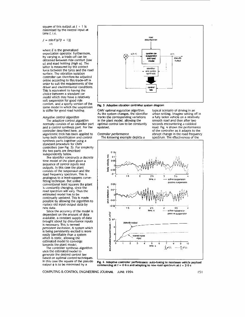
normally consists of an identifier part and a control synthesis part. For the controller described here, an algorithmic trick has been applied to lump both identification and control synthesis parts together using a standard procedure for CMV controllers (see Fig. 3). For simplicity the two parts are described independently below.
The identifier constructs a discrete time model of the plant given a sequence of control inputs and outputs. In this case the plant consists of the suspension and the road frequency spectrum. This is analogous to a least-squares curve- fitting technique. But unlike conventional least squares the plant is constantly changing. since the road spectrum will vary. Thus the estimated model has to be continually updated. This is made possible by allowing the algorithm to replace old input-output data by new data.
Since the accuracy of the model is dependent on the amount of data available, a constant supply of data brought about by disturbance inputs is necessary. This is termed persistent excitation. A system which is being persistently excited is more easily identifiable than a system which is static, allowing the estimated model to converge towards the plant model.
The controller synthesis algorithm uses the estimated model to generate the desired control law based on optimal control techniques. In this case the square of the pseudo output @ is to be minimised by a
U I R
road disturbances
and control synthesis
') - pseudo output
Fig. 3 Adaptive vibration controller system diagram
GMV optimal regulation algorithm. As the system changes, the identifier tracks the corresponding variations in the plant model, allowing the optimal control law to be constantly updated.
Controller performance The followine examDle deDicts a
typical scenario of driving in an urban setting. Imagine setting off in a fully laden vehicle on a relatively smooth road and then after two seconds encountering a cobbled road. Fig. 4 shows the performance of the controller as it adapts to the abrupt change in the road frequency sDectrum. The effectiveness of the
- . 1 1 5 2 2.5 3 3.5 4
time, s -- active suspension ~~~~ -passive suspension
0.02r
-002' 1 1.5 2 2.5 3 3.5 4
time, s active suspension U? . ~~~ passive suspension E
6 W r
input
1 2 3 4 5 6 7 8 9 IO
Fig. 4 Adaptive controller performance: auto-tuning to maximum vehicle payload commencing at t = 0.6 s and adapting to new road spectrum at t = 2.0 s
COMPUTING & CONTROL ENGINEERING JOURNAL JUNE 1994 151
disturbance inputs road inertial
x g F, strut deflection PID control I I
suspension strut defiectlon
velocity nala)l ua quarter car model I I bodv velocitv PI control
g. 5 Fast-levelling PID/PI controller system diagram
ground d v m i c I I disturbance
last-levelling control
:ig. 6 Composite controller system diagram
adaptive control algorithm is shown more clearly by comparing the accumulated squared pseudo output with that of the scaled noise input. When both have equal variances (indicated by parallel lines) optimal control is established whereby the system is fully converged. At 1.2 s into the simulation the estimated controller coefficients, initially set for the unladen vehicle configuration, are shown to auto-tune to the optimal values required for the fully laden vehicle. Then at 2 s the sharp slope due to the change in road spectrum is followed shortly by a near optimal performance as the controller adapts to the new road surface.
These results show some of the ride performance benefits obtainable from a fully adaptive suspension system. However, importance must be placed on the requirement of a high actuator bandwidth.
152
Fast-levelling control
I and hydraulic means of reducing the tilting of the car body in response to cornering or braking manoeuvres. The most common of these is the anti-roll bar designed to minimise body roll during cornering. However, all these passive techniques are only able to reduce the effects of inertial loads by a relatively small amount, not cancel them out completely.
Electronic control in suspensions provides a means of maintaining a level vehicle platform by completely cancelling out the dynamic loads experienced during manoeuvres. The result is a so-called fast-levelling controller. This is distinct from a slow-levelling controller used for cancelling static loads (e.g. jacking up the rear suspension to accommodate for extra payload in
n conventional suspensions, there are various mechanical
the boot]. Fast levelling control relies on hydraulic actuators to generate an opposing force to the dynamic loads experienced during manoeuvres. The idea is to monitor the deflections in the suspension struts and apply actuator forces according to some computer algorithm to drive these deflections to zero. The resulting body tilt is therefore greatly reduced.
Basic controller PID control is one of the most
widely used controller algorithms in use today with many industrial applications. The control law is often used for tracking or regulation whilst under the influence of loads. The acronym, standing for Proportional, Integral and Derivative, describes how the control signal is related to the output.
We now consider the application of PID to the quarter car model described above. The objective here is to cancel out the vertical dynamic loads on the car body thus maintaining the body at a constant height above the wheel. [The principle is the same as that for cancelling roll and pitch moments experienced during cornering and braking.) As with the GMV controller described earlier, the sensed outputs are absolute body velocity and suspension strut deflection. For the fast-levelling controller operating by itself, the former output was found necessary for stability.'
Fig. 5 describes the fast-levelling controller for the quarter car model. A PID compensator is used for the strut output channel, and a PI controller for the body velocity channel.
This controller operating by itself has been shown to give rapid load cancellation. Peak deflections in the car body in response to down loads were reduced by more than 90% in comparison to a conventional passive suspension. The next stage is to interface this with the vibration isolation controller.
Composite suspension control s mentioned above, the objective of the composite A controller is to enable
vibration isolation and fast levelling to be performed together. This is made possible by combining the GMV controller, operating at high frequencies, with the fast-levelling controller operating at low frequencies. The resulting composite system required lowpass filtering of the fast-levelling control signals for overall stability. Fig. 6 depicts the composite control system with a 5 Hz bandwidth stabilising filter.
COMPUTING & CONTROL ENGINEERING JOURNAL JUNE 1994
Controller performance The performance of the controller
was demonstrated by observing the system response to combined road and inertial disturbances. Fig. 7 describes the simultaneous application of both these inputs. Simulations were carried out with a fixed GMV controller in the composite system.
The results shown in Fig. 7 indicate how the composite controller is able to perform both vibration isolation and fast levelling. Body velocity is very much reduced in comparison to the passive suspension and only slightly greater than the adaptive vibration controller (AVC) operating independently. Also strut deflection is maintained at around zero by the integrating action in the fast-levelling controller loop. The RMS results of this simulation indicate a 41 YO reduction in body acceleration at the expense of only 9% increase in tyre deflection compared to the passive suspension performance. These somewhat larger tyre deflections indicate only a small reduction in road holding. As mentioned above a single weighting parameter can be adjusted to vary the trade-off in order to improve road holding as required.
Conclusions composite active suspension controller has been designed A based on a 3DOF quarter car
model. The objective was to demonstrate the benefits of having two controllers operating in parallel: one to provide vibration isolation at high frequencies and the other to provide fast levelling at low frequencies. The former was designed as a fully adaptive controller based on optimal regulation methods.
The following conclusions were drawn. The adaptive vibration controller was shown by itself to successfully adapt to a different vehicle payload and to an abrupt change in the road frequency spectrum. It also has the flexibility of varying the trade-off requirement between ride comfort and road holding by adjusting a single weighting parameter. The composite controller was shown to meet the requirements of both vibration isolation from the road disturbances and fast levelling in response to corneringibraking manoeuvres.
The results of this article clearly illustrate the benefits of relatively simple control algorithms for active suspension systems. The underlying assumption in the design, particularly for the high-frequency GMV controller, is a high actuator
c m
bandwidth. Much development is therefore required in practice for actuator hardware to meet the demands of such bandwidths. Although the results of this article have clearly demonstrated the benefits of composite control and adaptive vibration control in suspension design there still remains many areas which need to be considered in the overall design process. Some of this will be discussed in the following section.
Design implications and further work Design implications
I assumptions have been made. In particular, control studies have been based on a linear model in which the
n this article simulations are reported in which many
'>.' passive
actuator was modelled as a simple high-bandwidth force generator. Furthermore, perfect sensor information was also assumed. In practice, however, the situation would be very different and as an acknowledgment of this fact some of the practical implications are summarised. The intention is to highlight only some of the many difficulties in the development of fast-levelling and adaptive vibration controllers for practical active suspensions.
For the relatively high demands on actuator bandwidth some form of hydraulic suspension may be suitable. Typical systems today are the hydropneumatic Toyota suspension2 or the fully hydraulic Lotus suspension.' The latter relies on a mechanical spring to provide
E
2 3 4 5 6 time. s
- 5 6
0 4G - s active t
"*
a
1 2 3 4 5 6 lime, s
oo2r composite
strut reference
Fig. 7 Composite controller performance; response to 0.4 g cornering on rough road: (a) Disturbance inputs; and [b] Suspension performance
COMPUTING 6i CONTROL ENGINEERING JOURNAL JUNE 1994 153
Fig. 8 Schematic of proposed full car composite control system
the compliance and is designed for high bandwidth active ride as well as fast levelling. As with all hydraulic systems, flow inertance, bulk effects and pipe flow resistance will be present as well as nonlinearities such as flow rate limits in the control valves.
As mentioned in the modelling section, body-mounted accelerometers and suspension strut deflection sensors are required. These must be high-bandwidth sensors. The deflection sensor may be in the form of a non-contact linear variable inductance transducer (LVIT). Nonlinearities and signal drift will be present in sensor information. Digitising signals for computations will also result in further inaccuracies.
The controller algorithm will require a sufficient memory capacity to store various controller coefficients and related parameters. A sample rate of at least 100 Hz would be necessary for online computations.
Further work Much work is yet required in the
design and testing of the composite controller before full-scale implementation. The next stage in testing would naturally be to investigate the adaptive performance of the GMV controller whilst operating together with the fast-levelling controller as a composite duo. Further developments are then necessary to both the model and the controller. Some of these are discussed below.
For the model a number of areas need to be addressed. More realistic hardware modelling such as actuator valves and sensors would be the next step in the development. Also
154
in practice there are a number of nonlinearities which need to be considered in the model such as flow rate limits in control valves. Eventually a full car model must be
Engineering Centre of Lucas Industries for both technical and financial support. Finally, acknowledgments are due to the Science & Engineering Research
developed with four adaptive vibration controllers operating local to the suspension struts and a global PlDiPl controller to separately control the roll, pitch and heave motions of the car body during cornering and braking (see Fig. 8).
The further developments in the controller are mainly in the application of more sophisticated controller algorithms.4 Further improvements in performance can be obtained by correlating the front and rear wheel inputs in the full car model. This is where the front wheel disturbances can be used as preview information for the rear suspension controllers to provide further comfort in the back seat. For the fast- levelling controller with more realistic actuator bandwidth limitations feedforward control would offer further stability using advanced information from the steering wheel and brake pedal during cornering and braking manoeuvres, respectively.
The above suggestions are only some of the ideas required t o take the work forward. Nevertheless, it is hoped that the composite nature of the suspension control system and its adaptability will help pave the way to further research in this area.
Acknowledgments he author is in debt to Prof. P E. Wellstead for his invaluable T guidance in supervising the
PhD project on which this work is based.8 The author also wishes to thank the Control Systems Department of the Advanced
Council for funding the entire project.
References 1 BAKER, A.: 'Lotus' active suspension',
Automotive Engineer, February/March 1984, 9, ( l ) , pp.56-57
2 GOTO, T, KIZU. R., SATO, H., ONUMA, T. and OHNO, H.: 'Toyota active control suspension system for the 1989 Celica', Toyota Motor Co., 22nd ISATA. 90007, May 1990, pp.857-864
3 WELLSTEAD. P. E., and ZARROP, M. B.: 'Self-tuning systems: control and signal processing' (John Wiley 15 Sons, 1991)
4 BmEAD, R. R., CEVERS, M., and WERTS, V.: 'Adaptive optimal control: the thinking man's GPC' (Prentice Hall, 1990)
5 CLARKE, D. W., and GAWTHROP, P. J.: 'Self-tuning controller'. Proc. /E€.
6 COSTIN, M. H., and ELZINCA, D. R.: 1975, 122, (91, pp.929-934
'Active reduction of low-frequency tire impact noise using digital feedback control', /€€E Control Systems Magazine, August 1989, pp.3-6
7 KARNOPP, D.: 'Active suspensions based on fast load levelers, Vehicle System Dynamics, 1987, ( 1 6), pp.355-380
active suspension systems', PhD Thesis submitted to the University of Manchester, Faculty of Technology, 1992
8 TRUSCOTT, A. J.: 'Control studies in
0 IEE: 1994
Dr. Truscott was formerly a Research Associate with the Control Systems Centre, Department of Electrical Engineering &- Electronics, UMIST, Jackson Mill Building, PO Box 88. Manchester M60 IQD, UK. He is now working in the Powertrain Control Department of Ricardo Consulting Engineers Ltd., Bridge Works, Shoreham- by-Sea, West Sussex BN43 5FC. UK