COMPOSITE BEAM EFFECTS AND IMPLICATIONS TO SEISMIC DESIGN PROVISIONS Hammad EL JISR 1 , Dimitrios LIGNOS 2 ABSTRACT Previous studies have investigated the slab effects on the cyclic behavior of composite beams in moment-resisting frames. Of interest in this paper, is the slab contribution to the flexural strength and effective stiffness of the beam. The former influences the strong column/weak beam ratio while the latter affects the fulfillment of serviceability limits. For this purpose, experimental data of composite beams from prior subassembly and frame system tests are assembled in a consistent database format. This database facilitates the evaluation of code-based approaches that are adopted in the seismic design of composite beams in steel moment-resisting frames. In particular, the developed database is used to assess the plastic flexural strength and effective stiffness of the beams according to the current Eurocode, US and Japanese seismic provisions. The database is also used to quantify the plastic rotation capacity of composite beams that is particularly important for nonlinear seismic assessment. In general, all three design codes estimate the sagging plastic moment resistance of the beams reasonably well. On the other hand, the estimated effective stiffness shows greater variability. The proposed composite beam effective stiffness according to the Japanese seismic provisions is found to be the most accurate between the three design provisions. Results also suggest that the plastic deformation capacity of composite beams is higher under sagging bending than hogging bending due to the slab restraint. Although inconclusive, the framing action seems to enhance the plastic deformation capacity of beams intersecting interior joints. Keywords: Steel moment resisting frames; Plastic moment resistance; Composite action; Plastic deformation capacity; Seismic assessment 1. INTRODUCTION Steel moment-resisting frames (MRFs) are commonly used in highly seismic regions to provide lateral load resistance. In an attempt to mitigate the earthquake-induced collapse risk of steel MRFs, seismic design codes have adopted capacity design principles that permit structural damage in controlled dissipative fuses. The strong-column-weak-beam (SCWB) ratio imposed in seismic provisions aims at preventing the development of plastic hinges in the columns, and hence the potential collapse due to soft story mechanisms. There is a considerable variability when it comes to the SCWB ratio, with European, US and Japanese provisions adopting values of 1.3, 1.1 and 1.5 respectively (AIJ 2010; AISC 2016a; CEN 2004a; b). All three codes ignore the composite action in the formulation of the SCWB ratio. Additionally, in order to fulfill story drift limits for MRFs, design codes impose serviceability requirements. These include both lateral drift and beam deflection checks. Several tests have been conducted in the past 30 years to assess the effect of composite action on steel MRFs subjected to seismic loading. Uang et al. (2000) tested deep 912 mm beams with reduced beam sections (RBS) and showed that the slab increases the beam flexural strength under sagging bending by around 10%. Subassembly tests conducted by Jones et al. (2002) showed that the slab amplifies the beam flexural strength by up to 17% under sagging bending. Civjan et al. (2001) tested shallower beams 1 PhD Candidate, École Polytechnique Fédérale de Lausanne, Lausanne, Switzerland, [email protected]2 Associate Professor, School of Architecture Civil and Environmental Engineering, École Polytechnique Fédérale de Lausanne, Lausanne, Switzerland, [email protected]
Transcript
COMPOSITE BEAM EFFECTS AND IMPLICATIONS TO SEISMIC
DESIGN PROVISIONS
Hammad EL JISR1, Dimitrios LIGNOS2
ABSTRACT
Previous studies have investigated the slab effects on the cyclic behavior of composite beams in moment-resisting
frames. Of interest in this paper, is the slab contribution to the flexural strength and effective stiffness of the beam.
The former influences the strong column/weak beam ratio while the latter affects the fulfillment of serviceability
limits. For this purpose, experimental data of composite beams from prior subassembly and frame system tests are
assembled in a consistent database format. This database facilitates the evaluation of code-based approaches that
are adopted in the seismic design of composite beams in steel moment-resisting frames. In particular, the developed
database is used to assess the plastic flexural strength and effective stiffness of the beams according to the current
Eurocode, US and Japanese seismic provisions. The database is also used to quantify the plastic rotation capacity
of composite beams that is particularly important for nonlinear seismic assessment. In general, all three design
codes estimate the sagging plastic moment resistance of the beams reasonably well. On the other hand, the
estimated effective stiffness shows greater variability. The proposed composite beam effective stiffness according
to the Japanese seismic provisions is found to be the most accurate between the three design provisions. Results
also suggest that the plastic deformation capacity of composite beams is higher under sagging bending than
hogging bending due to the slab restraint. Although inconclusive, the framing action seems to enhance the plastic
deformation capacity of beams intersecting interior joints.
Keywords: Steel moment resisting frames; Plastic moment resistance; Composite action; Plastic deformation
capacity; Seismic assessment
1. INTRODUCTION
Steel moment-resisting frames (MRFs) are commonly used in highly seismic regions to provide lateral
load resistance. In an attempt to mitigate the earthquake-induced collapse risk of steel MRFs, seismic
design codes have adopted capacity design principles that permit structural damage in controlled
dissipative fuses. The strong-column-weak-beam (SCWB) ratio imposed in seismic provisions aims at
preventing the development of plastic hinges in the columns, and hence the potential collapse due to
soft story mechanisms. There is a considerable variability when it comes to the SCWB ratio, with
European, US and Japanese provisions adopting values of 1.3, 1.1 and 1.5 respectively (AIJ 2010; AISC
2016a; CEN 2004a; b). All three codes ignore the composite action in the formulation of the SCWB
ratio. Additionally, in order to fulfill story drift limits for MRFs, design codes impose serviceability
requirements. These include both lateral drift and beam deflection checks.
Several tests have been conducted in the past 30 years to assess the effect of composite action on steel
MRFs subjected to seismic loading. Uang et al. (2000) tested deep 912 mm beams with reduced beam
sections (RBS) and showed that the slab increases the beam flexural strength under sagging bending by
around 10%. Subassembly tests conducted by Jones et al. (2002) showed that the slab amplifies the
beam flexural strength by up to 17% under sagging bending. Civjan et al. (2001) tested shallower beams
1PhD Candidate, École Polytechnique Fédérale de Lausanne, Lausanne, Switzerland, [email protected] 2Associate Professor, School of Architecture Civil and Environmental Engineering, École Polytechnique Fédérale
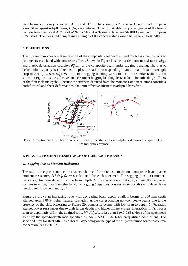
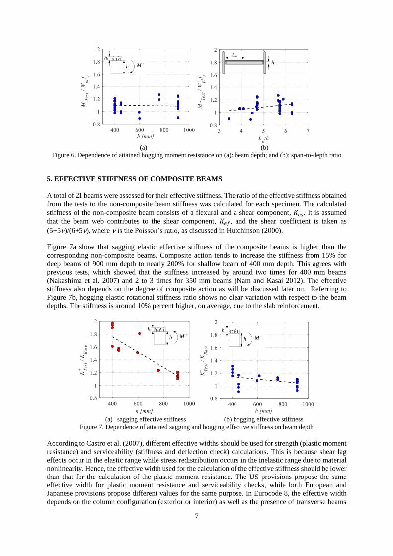
Figure 7. Dependence of attained sagging and hogging effective stiffness on beam depth
According to Castro et al. (2007), different effective widths should be used for strength (plastic moment
resistance) and serviceability (stiffness and deflection check) calculations. This is because shear lag
effects occur in the elastic range while stress redistribution occurs in the inelastic range due to material
nonlinearity. Hence, the effective width used for the calculation of the effective stiffness should be lower
than that for the calculation of the plastic moment resistance. The US provisions propose the same
effective width for plastic moment resistance and serviceability checks, while both European and
Japanese provisions propose different values for the same purpose. In Eurocode 8, the effective width
depends on the column configuration (exterior or interior) as well as the presence of transverse beams
h M -ht
h
Lo
`
h M +ht
h M -ht
8
and anchored rebar in the slab (CEN 2004b).
Both Eurocode 8 and Japanese recommendations for limit state design (AIJ LSD) specify a fixed value
for the modular ratio (n = 7 and n = 15, respectively) (AIJ 2010; CEN 2004b). It is worth noting that the
modular ratio value adopted in the Japanese provisions is more than twice as high than that of the US
and European provisions. Elastic transformed section analysis is adopted by the design codes to calculate
the effective stiffness of the composite beam. The Eurocode approach has no formulation for obtaining
the stiffness of partially composite beams. The US and Japanese provisions consider the degree of
composite action in the calculation of composite beam stiffness through the following approximation
(AIJ 2010; AISC 2016c):
𝐼𝑒𝑞𝑢𝑖𝑣 = 𝐼𝑛𝑜𝑛−𝑐𝑜𝑚𝑝 + × ( 𝐼𝑐𝑜𝑚𝑝 − 𝐼𝑛𝑜𝑛−𝑐𝑜𝑚𝑝) (1)
in which, 𝐼𝑒𝑞𝑢𝑖𝑣, 𝐼𝑐𝑜𝑚𝑝 and 𝐼𝑛𝑜𝑛−𝑐𝑜𝑚𝑝 are the moments of inertia of the partially composite, fully
composite and non-composite beam, respectively.
Leon (1990) and Leon and Alsamsam (1993) recommended a 25% reduction in the composite beam
stiffness for realistic deflection calculations. This recommendation is adopted in AISC 360-16 (AISC
2016c). Japanese limit state design recommendations account for this reduction by using a larger
modular ratio, n = 15 (AIJ 2010).
The effective stiffness under sagging bending was calculated from the composite beam stiffness. Both
the flexural and shear components of the stiffness were considered. It was assumed that the beam web
contributes to the shear stiffness as mentioned earlier. The ratio of the attained to calculated effective
stiffness under sagging bending was plotted against the beam depth and degree of composite action for
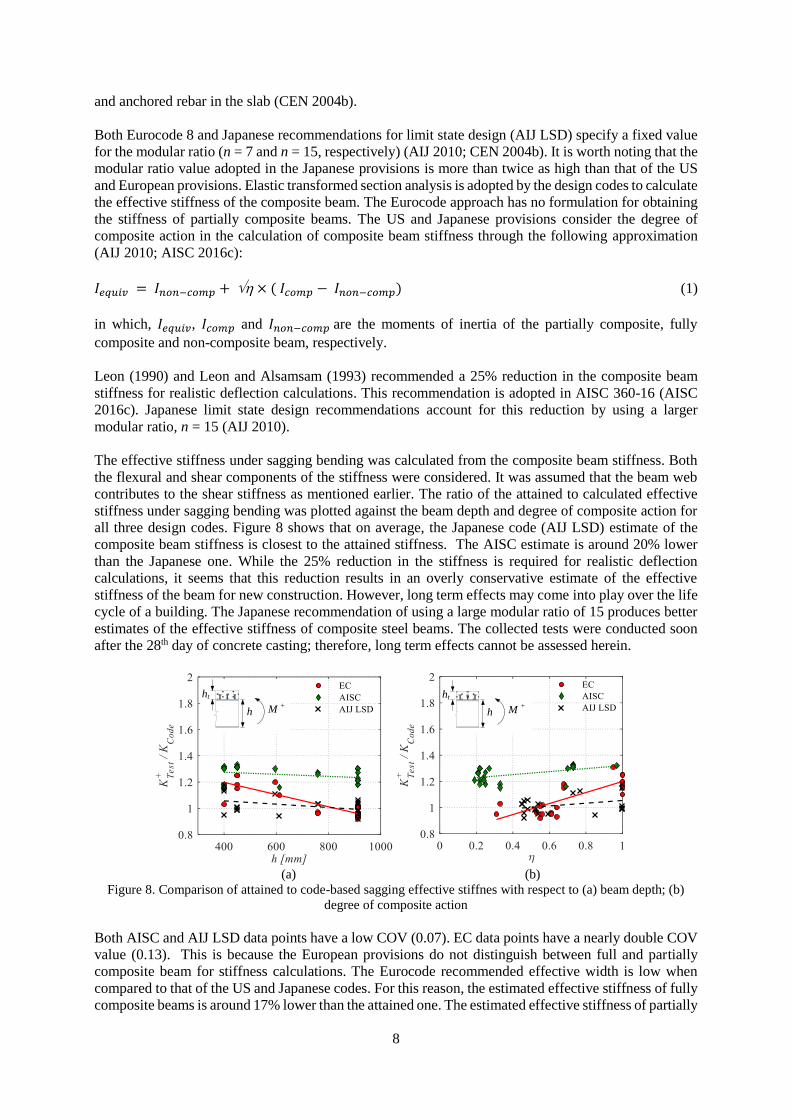
all three design codes. Figure 8 shows that on average, the Japanese code (AIJ LSD) estimate of the
composite beam stiffness is closest to the attained stiffness. The AISC estimate is around 20% lower
than the Japanese one. While the 25% reduction in the stiffness is required for realistic deflection
calculations, it seems that this reduction results in an overly conservative estimate of the effective
stiffness of the beam for new construction. However, long term effects may come into play over the life
cycle of a building. The Japanese recommendation of using a large modular ratio of 15 produces better
estimates of the effective stiffness of composite steel beams. The collected tests were conducted soon
after the 28th day of concrete casting; therefore, long term effects cannot be assessed herein.
(a) (b)
Figure 8. Comparison of attained to code-based sagging effective stiffnes with respect to (a) beam depth; (b)
degree of composite action
Both AISC and AIJ LSD data points have a low COV (0.07). EC data points have a nearly double COV
value (0.13). This is because the European provisions do not distinguish between full and partially
composite beam for stiffness calculations. The Eurocode recommended effective width is low when
compared to that of the US and Japanese codes. For this reason, the estimated effective stiffness of fully
composite beams is around 17% lower than the attained one. The estimated effective stiffness of partially
h M +ht
h M +ht
9
composite beams with 𝜂 < 0.8 is around 8% higher than the attained. As previously mentioned, Eurocode
8 adopts a minimum value of 𝜂 = 0.8. Hence, for deflection checks of composite beams with 𝜂 ≥ 0.8,
the stiffness estimate is on the conservative side as in AISC 360-16. For the purpose of calculating the
effective stiffness of partially composite beams with 𝜂 < 0.8, Eurocode yields unconservative estimates.
6. PLASTIC DEFORMATION CAPACITY OF COMPOSITE BEAMS
The assembled database was used to obtain the plastic deformation capacity of the beams, 𝜃𝑝,80%+ , under
sagging and hogging moments. Thirty beams are part of subassembly specimens that were subjected to
cyclic loading and the remaining five beams are part of full frame tests. Beams in which early fracture
occurred were excluded. Moreover, some of the tests were terminated before a strength drop of 20%
occurred. Lower bound values were provided for the corresponding data points.
According to Lignos and Krawinkler (2011), the web slenderness is the main contributor to the pre-
capping plastic rotation especially in deep and slender beams, which are typical in the North American
steel construction practice. This is because web local buckling is triggered first in most cases followed
by flange local buckling. The 𝜃𝑝,80%+ , was plotted against the beam web slenderness 𝑐/𝑡𝑤 where 𝑐 is the
fillet-to-fillet web height, and 𝑡𝑤 is the web thickness.
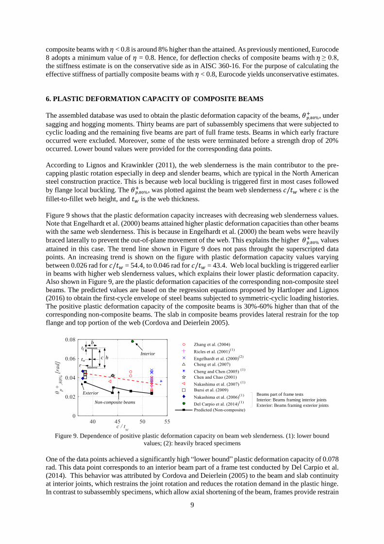
Figure 9 shows that the plastic deformation capacity increases with decreasing web slenderness values.
Note that Engelhardt et al. (2000) beams attained higher plastic deformation capacities than other beams
with the same web slenderness. This is because in Engelhardt et al. (2000) the beam webs were heavily
braced laterally to prevent the out-of-plane movement of the web. This explains the higher 𝜃𝑝,80%+ values
attained in this case. The trend line shown in Figure 9 does not pass throught the superscripted data
points. An increasing trend is shown on the figure with plastic deformation capacity values varying
between 0.026 rad for 𝑐/𝑡𝑤 = 54.4, to 0.046 rad for 𝑐/𝑡𝑤 = 43.4. Web local buckling is triggered earlier
in beams with higher web slenderness values, which explains their lower plastic deformation capacity.
Also shown in Figure 9, are the plastic deformation capacities of the corresponding non-composite steel
beams. The predicted values are based on the regression equations proposed by Hartloper and Lignos
(2016) to obtain the first-cycle envelope of steel beams subjected to symmetric-cyclic loading histories.
The positive plastic deformation capacity of the composite beams is 30%-60% higher than that of the
corresponding non-composite beams. The slab in composite beams provides lateral restrain for the top
flange and top portion of the web (Cordova and Deierlein 2005).
Figure 9. Dependence of positive plastic deformation capacity on beam web slenderness. (1): lower bound
values; (2): heavily braced specimens
One of the data points achieved a significantly high “lower bound” plastic deformation capacity of 0.078
rad. This data point corresponds to an interior beam part of a frame test conducted by Del Carpio et al.
(2014). This behavior was attributed by Cordova and Deierlein (2005) to the beam and slab continuity
at interior joints, which restrains the joint rotation and reduces the rotation demand in the plastic hinge.
In contrast to subassembly specimens, which allow axial shortening of the beam, frames provide restrain
b
tw
r
tf
c h
Non-composite beams
Interior
Exterior Beams part of frame tests
Interior: Beams framing interior joints
Exterior: Beams framing exterior joints
10
against axial shortening. Although inconclusive, this framing action increases the plastic deformation
capacity of interior beams. The authors are currently investigating this issue.
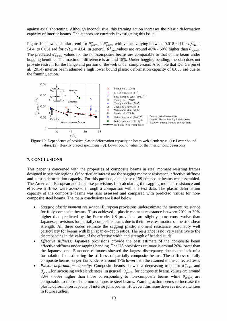
Figure 10 shows a similar trend for 𝜃𝑝,80%− as 𝜃𝑝,80%
+ with values varying between 0.018 rad for 𝑐/𝑡𝑤 =
54.4, to 0.031 rad for 𝑐/𝑡𝑤 = 43.4. In general, 𝜃𝑝,80%+ values are around 40% - 50% higher than 𝜃𝑝,80%
− .
The predicted 𝜃𝑝,80%− values for the non-composite beams are comparable to that of the beam under
hogging bending. The maximum difference is around 15%. Under hogging bending, the slab does not
provide restrain for the flange and portion of the web under compression. Also note that Del Carpio et
al. (2014) interior beam attained a high lower bound plastic deformation capacity of 0.055 rad due to
the framing action.
Figure 10. Dependence of positive plastic deformation capacity on beam web slenderness. (1): Lower bound
values, (2): Heavily braced specimens, (3): Lower bound value for the interior joint beam only
7. CONCLUSIONS
This paper is concerned with the properties of composite beams in steel moment resisting frames
designed in seismic regions. Of particular interest are the sagging moment resistance, effective stiffness
and plastic deformation capacity. For this purpose, a database of 39 composite beams was assembled.
The American, European and Japanese provisions for calculating the sagging moment resistance and
effective stiffness were assessed through a comparison with the test data. The plastic deformation
capacity of the composite beams was also assessed and compared with predicted values for non-
composite steel beams. The main conclusions are listed below:
Sagging plastic moment resistance: European provisions underestimate the moment resistance
for fully composite beams. Tests achieved a plastic moment resistance between 20% to 30%
higher than predicted by the Eurocode. US provisions are slightly more conservative than
Japanese provisions for partially composite beams due to their lower estimation of the stud shear
strength. All three codes estimate the sagging plastic moment resistance reasonably well
particularly for beams with high span-to-depth ratios. The resistance is not very sensitive to the
discrepancies in the values of the effective width and strength of headed studs.
Effective stiffness: Japanese provisions provide the best estimate of the composite beam
effective stiffness under sagging bending. The US provisions estimate is around 20% lower than
the Japanese one. Eurocode estimates showed the largest discrepancy due to the lack of a
formulation for estimating the stiffness of partially composite beams. The stiffness of fully
composite beams, as per Eurocode, is around 17% lower than the attained in the collected tests.
Plastic deformation capacity: Composite beams showed a decreasing trend for 𝜃𝑝,80%+ and
𝜃𝑝,80%− for increasing web slenderness. In general, 𝜃𝑝,80%
+ for composite beams values are around
30% - 60% higher than those corresponding to non-composite beams while 𝜃𝑝,80%− are
comparable to those of the non-composite steel beams. Framing action seems to increase the
plastic deformation capacity of interior joint beams. However, this issue deserves more attention
in future studies.
Non-composite beams
Interior
Exterior
Exterior
Beams part of frame tests
Interior: Beams framing interior joints
Exterior: Beams framing exterior joints
b
tw
r
tf
c h
11
8. ACKNOWLEDGMENTS
This study is based on work supported by the Swiss National Science Foundation (Project No.
200021_169248). The financial support is gratefully acknowledged. Any opinions expressed in the
paper are those of the authors and do not necessarily reflect the views of sponsors. The authors would
like to sincerely thank Professor Masayoshi Nakashima, Professor Tomohiro Matsumiya, Professor
Gregory Deierlein, Dr. Paul Cordova and Dr. Maikol Del Carpio for providing test data for the
development of the composite beams database.
7. REFERENCES
AIJ. (2010). Recommendation for limit state design of steel structures. Architectural Institute of Japan. AISC. (2016a). Seismic provisions for structural steel buildings, ANSI/AISC 341-16. American Institute for Steel
Construction, Chicago, IL. AISC. (2016b). Prequalified connections for special and intermediate steel moment frames for seismic
applications, ANSI/AISC 358-16. American Institute for Steel Construction, Chicago, IL. AISC. (2016c). Specification for structural steel buildings, ANSI/AISC 360-16. American Institute for Steel
Construction, Chicago, IL. ASCE. (2014). Seismic Evaluation and Retrofit of Existing Buildings. American Society of Civil Engineers,
Reston, VA. Bursi, O., Haller, M., Lennon, T., Ferrario, F., Bianco, L., Mallardo, R., Demonceau, J., Franssen, J., Jaspart, J.,
Hanus, F., Plumier, A., Bayo, E., Gracia, J., Alderighi, E., Braconi, A., and Salvatore, W. (2009). Prefabricated
composite beam-to-column filled tube or partially reinforced-concrete-encased column connections for severe
seismic and fire loadings. Directorate-General for Research Research Fund for Coal and Steel Unit. Castro, J. M., Elghazouli, A. Y., and Izzuddin, B. A. (2007). “Assessment of effective slab widths in composite
beams.” Journal of Constructional Steel Research, 63(10), 1317–1327.
CEN. (2004a). EN 1994-1-1: Eurocode 4: Design of composite steel and concrete structures – Part 1-1: General
rules and rules for buildings. CEN. (2004b). EN 1998-1: Eurocode 8: Design of structures for earthquake resistance – Part 1: General rules,
seismic actions and rules for buildings.
Chen, S.-J., and Chao, Y. C. (2001). “Effect of composite action on seismic performance of steel moment
connections with reduced beam sections.” Journal of Constructional Steel Research, 57(4), 417–434. Cheng, C.-T., Chan, C.-F., and Chung, L.-L. (2007). “Seismic behavior of steel beams and CFT column moment-
resisting connections with floor slabs.” Journal of Constructional Steel Research, 63(11), 1479–1493. Cheng, C.-T., and Chen, C.-C. (2005). “Seismic behavior of steel beam and reinforced concrete column
connections.” Journal of Constructional Steel Research, 61(5), 587–606. Civjan, S., Engelhardt, M., and Gross, J. (2001). “Slab effects in SMRF retrofit connection tests.” Journal of
Structural Engineering, 127(3), 230–237. Cordova, P. P., and Deierlein, G. (2005). Validation of the seismic performance of composite RCS frames: Full-
scale testing, analytical modeling, and seismic design. John A. Blume Earthquake Engineering Center Report,
Stanford University, Stanford, CA. Del Carpio, M., Mosqueda, G., and Lignos, D. (2014). Hybrid simulation of the seismic response of a steel moment
frame building structure through collapse. Technical Report, University at Buffalo, State University of New York. Du Plessis, D. P., and Daniels, J. H. (1972). Strength of Composite Beam to Column Connections. Report. Elkady, A., and Lignos, D. G. (2014). “Modeling of the composite action in fully restrained beam-to-column
connections: implications in the seismic design and collapse capacity of steel special moment frames.” Earthquake
12
Engineering & Structural Dynamics, 43(13), 1935–1954. Engelhardt, M., Venti, M., Fry, G., Jones, S., and Holliday, S. (2000). Behavior and design of radius-cut reduced
beam section connections. SAC Joint Venture. Hartloper, A., and Lignos, D. (2016). “Updates to the ASCE-41-13 nonlinear modelling provisions for
performance-based seismic assessment of new and existing steel moment resisting frames.” McGill University,
Montreal. Hutchinson, J. R. (2000). “Shear coefficients for Timoshenko beam theory.” Journal of Applied Mechanics, 68(1),
87–92. Kim, Y.-J., Oh, S.-H., and Moon, T.-S. (2004). “Seismic behavior and retrofit of steel moment connections
considering slab effects.” Engineering Structures, 26(13), 1993–2005. Leon, R. (1990). “Serviceability of composite floors.” Proceedings of the 1990 National Steel Construction
Conference, AISC. Leon, R., and Alsamsam, I. (1993). “Performance and serviceability of composite floors.” Structural Engineering
in Natural Hazards Mitigation, ASCE, 1479–1484. Leon, R. T., Hajjar Jerome F., and Gustafson, M. A. (1998). “Seismic response of composite moment-resisting
connections. I: Performance.” ASCE Journal of Structural Engineering, 124(8), 868–876. Lignos, D., and Krawinkler, H. (2011). “Deterioration modeling of steel components in support of collapse
prediction of steel moment frames under earthquake loading.” ASCE Journal of Structural Engineering, 137(11),
1291–1302. Mele, E. (2002). “Moment resisting welded connections: an extensive review of design practice and experimental
research in USA, Japan and Europe.” Journal of Earthquake Engineering, 06(01), 111–145. Nakashima, M., Matsumiya, T., Suita, K., and Liu, D. (2006). “Test on full‐scale three‐storey steel moment frame
and assessment of ability of numerical simulation to trace cyclic inelastic behaviour.” Earthquake Engineering
and Structural Dynamics, 35(1), 3–19. Nakashima, M., Matsumiya, T., Suita, K., and Zhou, F. (2007). “Full-Scale test of composite frame under large
cyclic loading.” ASCE Journal of Structural Engineering, 133(2), 297–304. Nakashima, M., Roeder, C., and Maruoka, Y. (2000). “Steel moment frames for earthquakes in United States and
Japan.” ASCE Journal of Structural Engineering, 126(8), 861–868. Nam, T., and Kasai, K. (2012). “Study on Shake Table Experimental Results Regarding Composite Action of a
Full-Scale Steel Building Tested to Collapse.” 9th Int. Conference on Urban Earthquake Eng./4th Asia Conference
on Earthquake Engineering. Ricles, J. M., Fisher, J. W., Lu, L.-W., and Kaufmann, E. J. (2002). “Development of improved welded moment
connections for earthquake-resistant design.” Journal of Constructional Steel Research, North American Special
Issue, 58(5), 565–604. Tagawa, Y., Kato, B., and Aoki, H. (1989). “Behavior of composite beams in steel frame under hysteretic loading.”
ASCE Journal of Structural Engineering, 115(8), 2029–2045. Uang Chia-Ming, Yu Qi-Song “Kent,” Noel Shane, and Gross John. (2000). “Cyclic testing of steel moment
connections rehabilitated with RBS or welded haunch.” ASCE Journal of Structural Engineering, 126(1), 57–68. Yu, Q.-S., and Uang, C.-M. (2000). “Cyclic performance and retrofit design of pre-Northridge steel moment
connections with welded haunch.” Proceedings of the 12th WCEE, Auckland, New Zealand.
Zhang, X., Ricles, J., Lu, L.-W., and Fisher, J. (2004). Development of seismic guidelines for deep-column steel