Composite Construttion lor Continuity By Eivind Hognestad, Alan H. Mattock and Paul H. Kaar" (Presented during 1959 PCI Convention) SYNOPSIS Past activities of the PCA Research and Develop- ment Laboratories in the field of prestressed con- crete are reviewed, and the fundamental nature of this early work is emphasized. The highlights of a recent extensive laboratory investigation of continuous precast-prestressed concrete bridges are presented. The type of bridge under study includes precast 1-shaped girders con- nected into an integral bridge unit by a situ-cast deck slab. Continuity from span to span is obtained in such composite construction by placing de- formed bar reinforcement longitudinally in the deck slab across intermediate piers. The investiga- tion is being carried out in nine related stages, culminating with testing of a complete bridge deck over two spans. Aside from their application to the specific bridge problems involved, the results of these studies of composite construction have important bearing on building construction. Preparations are therefore in progress for similar broad studies of precast-prestressed buildings. Past Prestressing Work at PCA Laboratories I n mid- June of 1948, ground was broken in Skokie, Illinois, as the first step toward modern research and development facilities for the portland cement industry of the United States and Canada. The scientific institution that came into being during the decade that fol- lowed is devoted to all aspects of cement and concrete technology, from deeply basic research to highly practical engineering development. "Manager, Senior Development Engineer, and Development Engineer, respectively, Structural Development Section, Port- land Cement Association Research and Development Laboratories, Skokie, Illi- nois. March, 1960 Most of the work of the Portland Cement Association Laboratories has a direct or indirect bearing on the prestressing industry. For ex- ample, work on cement hydration has aided the development of ac- 59
Transcript
Composite Construttion lor Continuity By
Eivind Hognestad, Alan H. Mattock and Paul H. Kaar"
(Presented during 1959 PCI Convention)
SYNOPSIS
Past activities of the PCA Research and Development Laboratories in the field of prestressed concrete are reviewed, and the fundamental nature of this early work is emphasized.
The highlights of a recent extensive laboratory investigation of continuous precast-prestressed concrete bridges are presented. The type of bridge under study includes precast 1-shaped girders connected into an integral bridge unit by a situ-cast deck slab. Continuity from span to span is obtained in such composite construction by placing deformed bar reinforcement longitudinally in the deck slab across intermediate piers. The investigation is being carried out in nine related stages, culminating with testing of a complete bridge deck over two spans.
Aside from their application to the specific bridge problems involved, the results of these studies of composite construction have important bearing on building construction. Preparations are therefore in progress for similar broad studies of precast-prestressed buildings.
Past Prestressing Work at PCA Laboratories
I n mid-June of 1948, ground was broken in Skokie, Illinois, as the
first step toward modern research and development facilities for the portland cement industry of the
United States and Canada. The scientific institution that came into being during the decade that followed is devoted to all aspects of cement and concrete technology, from deeply basic research to highly practical engineering development.
"Manager, Senior Development Engineer, and Development Engineer, respectively, Structural Development Section, Portland Cement Association Research and Development Laboratories, Skokie, Illinois.
March, 1960
Most of the work of the Portland Cement Association Laboratories has a direct or indirect bearing on the prestressing industry. For example, work on cement hydration has aided the development of ac-
59
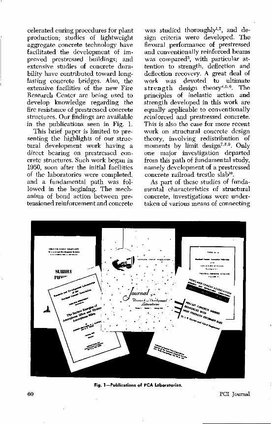
celerated curing procedures for plant production; studies of lightweight aggregate concrete technology have facilitated the development of improved prestressed buildings; and extensive studies of concrete durability have contributed toward longlasting concrete bridges. Also, the extensive facilities of the new Fire Research Center are being used to develop knowledge regarding the fire resistance of prestressed concrete structures. Our findings are available in the publications seen in Fig. 1.
This brief paper is limited to presenting the highlights of our structural development work having a direct bearing on prestressed concrete structures. Such work began in 1950, soon after the initial facilities of the laboratories were completed, and a fundamental path was followed in the begining. The mechanism of bond action between pretensioned reinforcement and concrete
was studied thoroughlyl·2, and design criteria were developed. The flexural performance of prestressed and conventionally reinforced beams was compared3, with particular attention to strength, deflection and deflection recovery. A great deal of work was devoted to ultimate strength design theory4•5 •6 . The principles of inelastic action and strength developed in this work are equally applicable to conventionally reinforced and prestressed concrete. This is also the case for more recent work on structural concrete design theory, involving redistribution of moments by limit design7
•8
•9
• Only one major investigation departed from this path of fundamental study, namely development of a prestressed concrete railroad trestle slab10•
As part of these studies of fundamental characteristics of structural concrete, investigations were undertaken of various means of connecting
Fig. 1-Publicatio,ns of PCA Laboratories.
60 PCI Journal
Fig. 2-Cross sectio'n of Structural Laboratory.
precast members into integral structures. It became evident that highly effective structural connections could be obtained at low cost by combined usage of precast and situ-cast concrete. Thus, we began laboratory investigations of composite construction.
The work of many investigators at home and abroad led to far-reaching changes and improvements in design theory in the mid-1950's. At the same time, growth of the prestressed concrete industry began to increase rapidly. It became clear that the evolution of structural concrete that began in the 1890's was becoming almost a revolution. It became clear that, to continue progress, largescale and complex experiments were needed to bridge the gaps between fundamental structural research and the engineering arts of practice, for which experiments no laboratory in the United States was adequately equipped. Thus, it became desirable for the Portland Cement Association
March, 1960
to build an unusual new structural laboratory facility.
PCA Structural Laboratory To accommodate large-scale tests
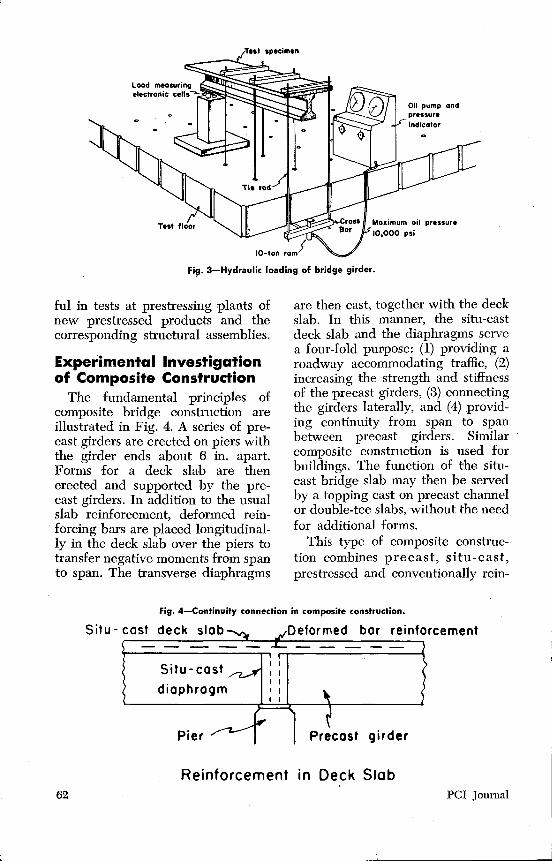
of structural assemblies, rather than individual components only, the PCA Structural Laboratory was built in an unusual manner. Instead of housing conventional testing machines, the laboratory was built as a giant testing machine in itself. As shown in Fig. 2, the laboratory contains a test floor built as a heavy box girder 12 ft. thick and 56 by 121 ft. in plan. Test structures are secured to this floor, and loads are applied by hydraulic rams acting through various arrangements of cross bars and tie rods, as illustrated by the example shown in Fig. 3.
In this manner, the facilities required for thorough studies of composite construction and other complex structural forms became available. The test methods which were developed11 may also be use-
61
I
L_
Fig. 3-Hydraulic loading of bridge girder.
ful in tests at prestressing plants of new prestressed products and the corresponding structural assemblies.
Experimental Investigation of Composite Construction
The fundamental principles of composite bridge construction are illustrated in Fig. 4. A series of precast girders are erected on piers with the girder ends about 6 in. apart. Forms for a deck slab are then erected and supported by the precast girders. In addition to the usual slab reinforcement, deformed reinforcing bars are placed longitudinally in the deck slab over the piers to transfer negative moments from span to span. The transverse diaphragms
are then cast, together with the deck slab. In this manner, the situ-cast deck slab and the diaphragms serve a four-fold pui'pose: (1) providing a roadway accommodating traffic, (2) increasing the strength and stiffness of the precast girders, (3) connecting the girders laterally, and (4) providing continuity from span to span between precast girders. Similar composite construction is used for buildings. The function of the situcast bridge slab may then be served by a topping cast on precast channel or double-tee slabs, without the need for additional forms.
This type of composite construction combines precast, situ-cast, prestressed and conventionally rein-
Fig. 4-Continuity connection in composite construction.
Situ- cast
Pier
Reinforcement in Deck Slab 62 PCI Journal
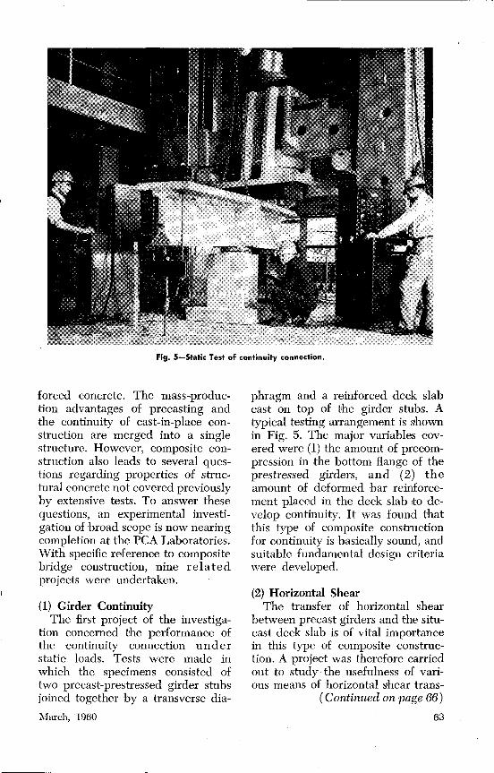
Fig. 5-Static Test of continuity connection.
forced concrete. The mass-production advantages of precasting and the continuity of cast-in-place construction are merged into a single structure. However, composite construction also leads to several questions regarding properties of structural concrete not covered previously by extensive tests. To answer these questions, an experimental investigation of broad scope is now nearing completion at the PCA Laboratories. With specific reference to composite bridge construction, nine related projects were undertaken.
(I) Girder Continuity The first project of the investiga
tion concerned the performance of the continuity connection under static loads. Tests were made in which the specimens consisted of two precast-prestressed girder stubs joined together by a transverse dia-
March, 1960
phragm and a reinforced deck slab cast on top of the girder stubs. A typical testing arrangement is &hown in Fig. 5. The major variables covered were (1) the amount of precompression in the bottom flange of the prestressed girders, and (2) the amount of deformed bar reinforcement placed in the deck slab to develop continuity. It was found that this type of composite construction for continuity is basically sound, and suitable fundamental design criteria were developed.
(2) Horizontal Shear The transfer of horizontal shear
between precast girders and the situcast deck slab is of vital importance in this type of composite construction. A project was therefore carried out to study the usefulness of various means of horizontal shear trans-
( Continued on page 66)
63
PRESTRESSED CONCRETE REPORT
DICKERSON USES LESCHEN
Leschen Strand selected for one of the largest strand patterns tensioned in Pennsylvania
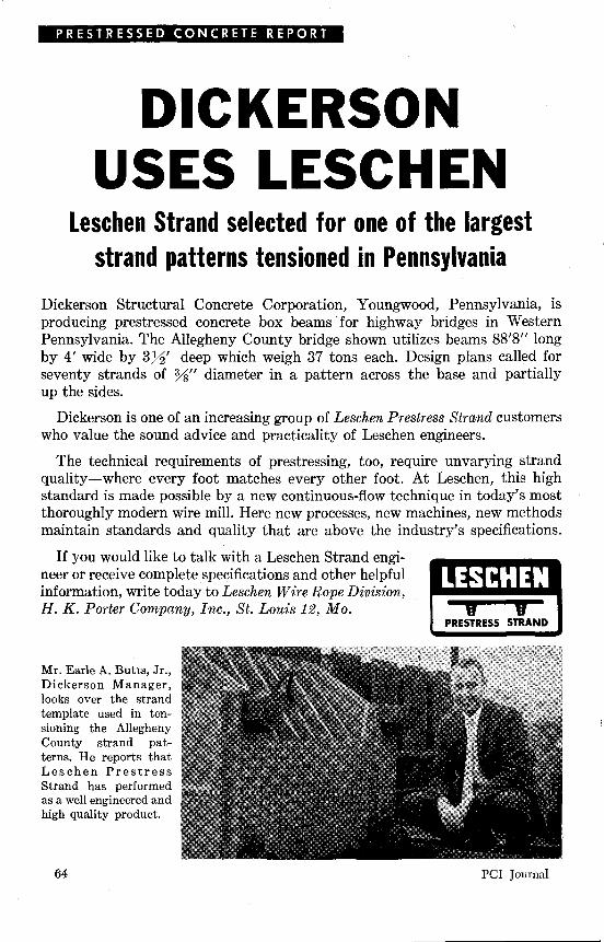
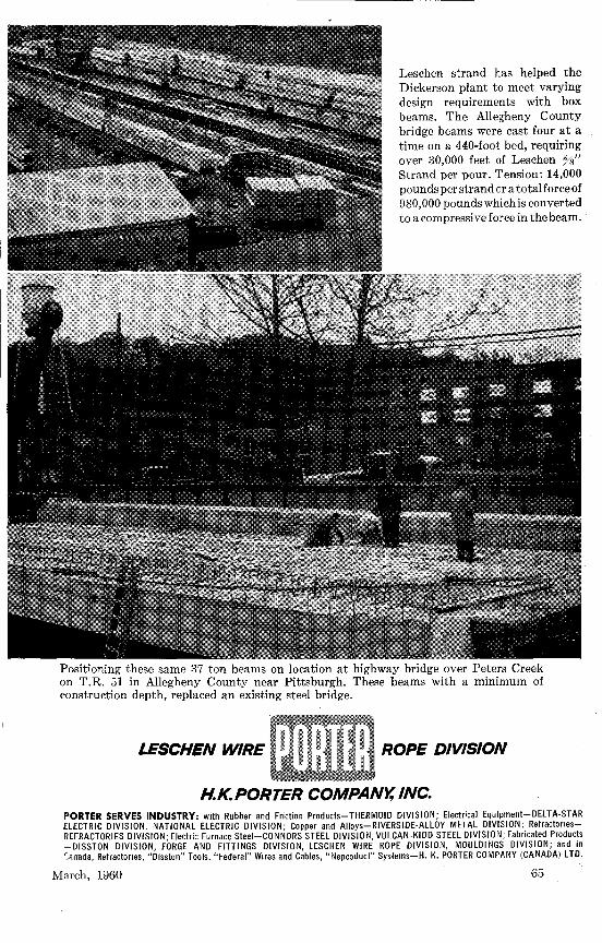
Dickerson Structural Concrete Corporation, Youngwood, Pennsylvania, is producing prestressed concrete box beams for highway bridges in Western Pennsylvania. The Allegheny County bridge shown utilizes beams 88'8" long by 4' wide by 372' deep which weigh 37 tons each. Design plans called for seventy strands of %" diameter in a pattern across the base and partially up the sides.
Dickerson is one of an increasing group of Leschen Prestress Strand customers who value the sound advice and practicality of Leschen engineers.
The technical requirements of prestressing, too, require unvarying strand quality-where every foot matches every other foot. At Leschen, this high standard is made possible by a new continuous-flow technique in today's most thoroughly modern wire mill. Here new processes, new machines, new methods maintain standards and quality that are above the industry's specifications.
If you would like to talk with a Leschen Strand engineer or receive complete specifications and other helpful information, write today to Leschen Wire Rope Division, H. K. Porter Company, Inc., St. Louis 12, Mo.
Mr. Earle A. Butts, Jr., Dickerson Manager, looks over the strand template used in tensioning the Allegheny County strand patterns. He reports that Leschen Prestress Strand has performed as a well engineered and high quality product.
64
LESCH EN
PCI Journal
Leschen strand has helped the Dickerson plant to meet varying design requirements with box beams. The Allegheny County bridge beams were cast four at a time on a 440-foot bed, requiring over 30,000 feet of Leschen %" Strand per pour. Tension: 14,000 pounds per strand or a totalforce of 980,000 poundswhichis converted to a compressive force in the beam.
Positioning these same 37 ton beams on location at highway bridge over Peters Creek on T.R. 51 in Allegheny County near Pittsburgh. These beams with a minimum of construction depth, replaced an existing steel bridge.
LESCHEN WIRE ROPE DIVISION
H.K. PORTER COMPANY, INC. PORTER SERVES INDUSTRY: with Rubber and Friction Products-THERMOID DIVISION; Electrical Equipment-DElTA-STAR ElECTRIC DIVISION, NATIONAl ElECTRIC DIVISION; Copper and Alloys-RIVERSIDE-AllOY METAl DIVISION; RefractoriesREFRACTORIES DIVISION; Electric Furnace Steel-CONNORS STEEl DIVISION, VUlCAN-KIDD STEEl DIVISION; Fabricated Products -DISSTON DIVISION, FORGE AND FITTINGS DIVISION, lESCHEN WIRE ROPE DIVISION, MOUlDINGS DIVISION; and in 'anada, Refractories, "Disston" Tools, "Federal" Wires and Cables, "Nepcoduct" Systems-H. K. PORTER COMPANY (CANADA) lTD.
March, 1960 65
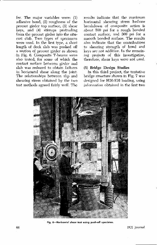
fer. The major variables were: (1) adhesive bond, (2) roughness of the precast girder top surface, (3) shear keys, and (4) stirrups protruding from the precast girder into the situcast clab. Two types of specimens were used. In the first type, a short length of deck slab was pushed off a section of precast girder as shown
·in Fig. 6. Composite T-beams were also tested, for some of which the contact surface between girder and slab was reduced to obtain failures in horizontal shear along the joint. The relationships between slip and shearing stress obtained by the two test methods agreed fairly well. The
results indicate that the maximum horizontal shearing stress before breakdown of composite action is about 500 psi for a rough bonded contact surface, and 300 psi for a smooth bonded surface. The results also indicate that the contributions to shearing strength of bond and keys are not additive. In the remaining projects of this investigation, therefore, shear keys were not used.
(3) Bridge Design Studies In this third project, the tentative
bridge structure shown in Fig. 7 was designed for H20-Sl6 loading, using information obtained in the first two
Fig. 6-H·o·rizontal shear test using push-off specimen.
66 PCI Journal
j.l·----- 66'-o" ------+------- 66'- o" ·I A
ELEVATION
SECTION A- A
Fig. 7-Composite bridge considered in design study.
projects of this investigation, in addition to design methods already available elsewhere. These design studies brought out a need for additional test data, and further projects of the investigation were then planned.
(4) Diagonal Tension Near intermediate supports, the
continuous composite girders were designed for flexure as conventionally reinforced concrete members. A question therefore arose regarding selection of a proper method of diagonal tension and web reinforcement design. Nominal shearing stresses, calculated on the basis of the web thickness of the precast girders, were unusually high, so that the web reinforcement required by customary reinforced concrete design methods seemed to be excessive. A project was therefore undertaken, involving tests of half-scale composite girders loaded by a group of point loads simulating the wheel loads of the H20-Sl6 design vehicle. The test girders were supported over a single span with a tied-down cantilever at one end, as seen in Fig. 8.
March, 1960
By suitably varying the tie-down force at the end of the cantilever independently from the vehicle loads, conditions were established in the single span corresponding to those existing in one span of a two-span continuous girder. The variables studied were (1) amount of vertical stirrup web reinforcement, and (2) location of the applied loads-that is, the degree of flexure combined with shear. The test results indicate that the presence of prestress in the precast girder has some beneficial effect on shearing strength even in regions of negative bending moment.
(5) Flexural Strength To extend the findings of the first
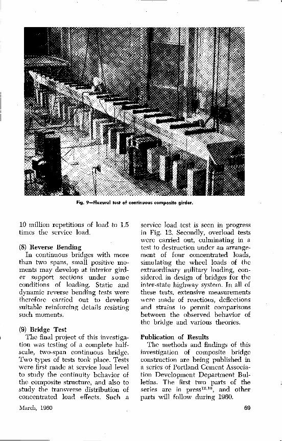
project to the particular conditions involved in the bridge structure shown in Fig. 7, tests were made of a half-scale single girder continuous over two spans. As shown in Fig. 9, a loading was selected to simulate the equivalent lane loading of H20-Sl6. The loads were arranged to give the most severe bending moment conditions at the intermediate support. The composite continuity
67
connection behaved in an entirely satisfactory manner. Full redistribution of bending moments took place before the ultimate strength was reached.
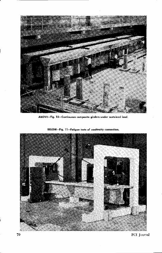
(6) Creep and Shrinkage Studies Two half-scale 66-ft. continuous
girders were placed under a sustained loading simulating dead load of the full-scale prototype 132 ft. long, as shown by Fig. 10. This was done to study effects of creep and differential shrinkage on the continuity behavior of the composite structure. Extensive measurements were made of strains, deflections and support reactions. It was found that, to ensure fully continuous behavior at service loads after an extended period of time, small reverse moments set up at interior supports by creep deformation must be provided for. This was accomplished by suitable
reinforcing details in one of the two girders.
(7) Fatigue Tests Although the strength of the com
posite structure was thoroughly studied for static loads earlier in this investigation, it was considered desirable also to study repeated load effects. As seen in Fig. 11, the halfscale specimens used simulated that part of a girder taken from the design study bridge which extends 20 ft. either side from the center support. The only variable involved in these fatigue tests was the maximum value of the pulsating load. The specimens were supported at the diaphragm and were loaded at both ends by pulsating rams. It was found that a composite connection, designed to have a static ultimate flexural strength 2.5 times the service load moment, can sustain safely over
Fig. 8-Diagonal tension test of composite girder.
68 PCI Journal
Fig. 9-Fiexural test of continu'ous composite girder.
10 million repetitions of load to 1.5 times the service load.
(8) Reverse Bending In continuous bridges with more
than two spans, small positive moments may develop at interior gird~ er support sections under some conditions of loading. Static and dynamic reverse bending tests were therefore carried out to develop suitable reinforcing details resisting such moments.
(9) Bridge Test The final project of this investiga
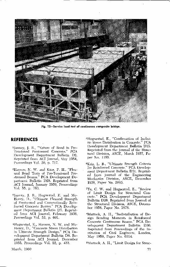
tion was testing of a complete halfscale, two-span continuous bridge. Two types of tests took place. Tests were first made at service load level to study the continuity behavior of the composite structure, and also to study the transverse distribution of concentrated load effects. Such a
March, 1960
service load test is seen in progress in Fig. 12. Secondly, overload tests were carried out, culminating in a test to destruction under an arrangement of four concentrated loads, simulating the wheel loads of the extraordinary military loading, considered in design of bridges for the inter-state highway system. In all of these tests, extensive measurements were made of reactions, deflections and strains to permit comparisons between the observed behavior of the bridge and various theories.
Publication of Results The methods and findings of this
investigation of composite bridge construction are being published in a series of Portland Cement Association Development Department Bulletins. The first two parts of the series are in press12•13, and other parts will follow during 1960.
69
ABOVE-Fig. 10-Continuous comp·osite girders under sustained load.
BELOW-Fig. 11-Fatigue tests of continuity connection.
70 PCI Journal
Fig. 12-Service fo·ad test of continuous co·mposite bridge.
REFERENCES
1 Janney, J. R., "Nature of Bond in PreTensioned Prestressed Concrete." PCA Development Department Bulletin D2. Reprinted from ACI Journal, May 1954, Proceedings Vol. 50, p. 717.
2Hanson, N. \V. and Kaar, P. H., "Flexural Bond Tests of Pre-Tensioned Prestressed Beams." PCA Development Department Bulletin D28. Reprinted from ACI Journal, January 1959, Proceedings Vol. 55, p. 783.
3Janney, J. R., Hognestad, E. and McHenry, D., "Ultimate Flexural Strength of Prestressed and Conventionally Reinforced Concrete Beams." PCA Development Department Bulletin D7. Reprinted from ACI Journal, February 1956, Proceedings Vol. 52, p. 601.
4Hognestad, E., Hanson, N. W. and McHenry, D., "Concrete Stress Distribution in Ultimate Strength Design." PCA Development Department Bulletin D6. Reprinted from ACI Journal, December 1955, Proceedings Vol. 52, p. 455.
March, 1960
5Hognestad, E., "Confirmation of Inelastic Stress Distribution in Concrete." PCA Development Department Bulletin D15. Reprinted from the Journal of the Structural Division, ASCE, March 1957, Paper No. 1189.
6Kriz, L. B., "Ultimate Strength Criteria .!:or Reinforced Concrete." PCA Development Department Bulletin D31. Reprinted from Journal of the Engineering Mechanics Division, ASCE, December 1958, Paper No. 2095.
7Yu, C. W. and Hognestad, E., "Review of Limit Design for Structural Concrete." PC:A Development Department Bulletin D26. Reprinted from Journal of the Structural Division, ASCE, December 1958, Paper 'No. 1878.
'Mattock, A. H., "Redistribution of Design Bending Moments in Reinforced Concrete Continuous Beams." PCA Development Department Bulletin D30. Reprinted from Proceedings of the Institution of Civil Engineers, London, May 1959, Paper No. 6314.
9Mattock, A. H., "Limit Design for Struc-
71
tural Concrete," PCA Journal of the Research and Development Laboratories, May 1959, Vol. 1, No. 2, p. 14.
lO"Prestressed Concrete R. R. Trestle Slab," Concrete for Railways, No. 44, Published by PCA, 1951.
llHognestad, E., Hanson, N. W., Kriz, L. B. and Kurvits, 0. A., "Facilities and Test Methods of PCA Structural Laboratory." PCA Development Department Bulletin D33. Reprinted from PCA Jour-
nal of the Research and Development Laboratories, 1959, Vol. 1, Nos. 1-3.
12Kaar, P. H., Kriz, L. B. and Hognestad E., "Precast-Prestressed Concrete Bridges, Part !-Pilot Tests of Continuous Girders," PCA Development Department Bulletin D34.
13Hanson, N. W., "Precast-Prestressed Concrete Bridges, Part 2-Horizontal Shear Connections," PCA Development Department Bulletin D35.
CONCLUDING REMARKS
An extensive investigation carried out in the new Structural Laboratory of the Portland Cement Association concerns composite construction in which combined usage is made of precast-prestressed bridge girders and a conventionally reinforced situcast deck slab. It is expected that the results of this experimental and analytical study will contribute importantly to the science and art of prestressed bridge design.
Aside from their application to the specific bridge problems in-
72
volved, the results of this investigation also contribute toward improvements in design and construction of composite building structures. To develop such application fully, a new investigation of similar scope is being planned for execution in 1960. Emphasis will be placed on composite buildings consisting of precast columns, girders and double-tee slabs, all connected together into an integral continuous structure by a situ-cast floor topping containing deformed bar reinforcement.