28
K1 Composite Gas Pipe System Installation Guidelines TM

K1Composite Gas
Pipe SystemInstallation Guidelines
TM
2
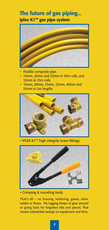
The future of gas piping...Iplex K1TM gas pipe system
• Crimping & rounding tools.
That’s all – no brazing, soldering, gases, silveroxides or fluxes. No lugging heaps of gear aroundor going back for forgotten bits and pieces. Thatmeans substantial savings on equipment and time.
• IPLEX K1TM high integrity brass fittings.
• Flexible composite pipe.• 16mm, 20mm and 25mm in 50m coils, and
32mm in 25m coils.• 16mm, 20mm, 25mm, 32mm, 40mm and
50mm in 5m lengths.

INTRODUCTION
This manual contains information
on the installation of the IPLEX K1TM
composite gas pipe and fittings
system.
The IPLEX K1TM system should be
installed as per the requirement of
AS 5601. The system is intended for
use by licensed gas fitters, trained
and accredited by Iplex in the IPLEX
K1TM system.
IPLEX K1TM offers an integrated
system that is flexible enough to be
bent by hand, is extremely light
weight and corrosion resistant. In
particular, no brazing or soldering is
necessary. When installed by a
trained and licensed tradesman, the
system is of high quality and
economical to use.
3
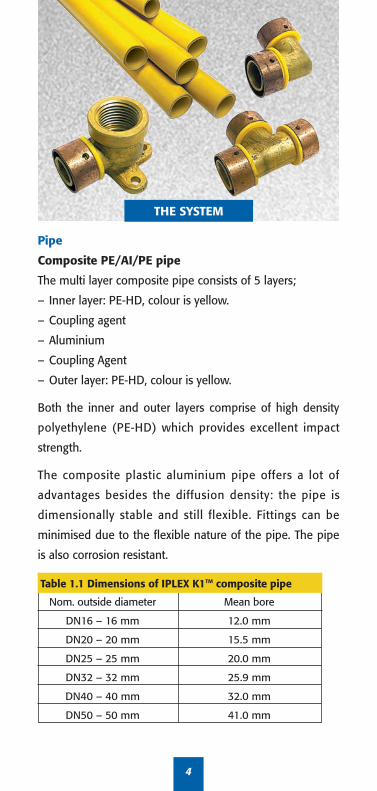
Pipe
Composite PE/AI/PE pipe
The multi layer composite pipe consists of 5 layers;
– Inner layer: PE-HD, colour is yellow.
– Coupling agent
– Aluminium
– Coupling Agent
– Outer layer: PE-HD, colour is yellow.
Both the inner and outer layers comprise of high density
polyethylene (PE-HD) which provides excellent impact
strength.
The composite plastic aluminium pipe offers a lot of
advantages besides the diffusion density: the pipe is
dimensionally stable and still flexible. Fittings can be
minimised due to the flexible nature of the pipe. The pipe
is also corrosion resistant.
Table 1.1 Dimensions of IPLEX K1TM composite pipe
Nom. outside diameter Mean bore
DN16 – 16 mm 12.0 mm
DN20 – 20 mm 15.5 mm
DN25 – 25 mm 20.0 mm
DN32 – 32 mm 25.9 mm
DN40 – 40 mm 32.0 mm
DN50 – 50 mm 41.0 mm
THE SYSTEM
4

5
Fittings
IPLEX K1TM gas fittings are specially designed and engineered
to complement the IPLEX K1TM aluminium plastic composite
pipe for gas use. The IPLEX K1TM system has a comprehensive
range of fittings that are suitable for general gas use. Each
box contains an informative installation instruction leaflet.
DR brass fittings
IPLEX K1TM brass fittings are fully dezincification resistant to
Australian Standards and are precision CNC machined. DR
brass is brass that has been heat treated and chemically
enhanced to make it resistant to the loss of zinc i.e.
dezincification resistant. Brass that is not dezincification
resistant can be subject to corrosion.
Copper crimp sleeves.
All IPLEX K1TM fittings have a copper crimp sleeve with a pipe
depth insertion window to provide visible assurance that the
pipe has been pushed fully home.
The copper crimp sleeves are held on the fitting by a
distinctive “gas yellow” crimp sleeve retainer.
Table 1.2 Dimensions of IPLEX K1TM composite pipe fittings
Nom. outside diameter Mean bore
DN16 – 16 mm 8.6 mm
DN20 – 20 mm 12.1 mm
DN25 – 25 mm 16.7 mm
DN32 – 32 mm 20.3 mm
DN40 – 40 mm 26.0 mm
DN50 – 50mm 34.7 mm

6
Crimping tools
The crimping tools are precision instruments engineered
to ensure a simple, effective joint. The principle of this
jointing method has been well proven in many
engineering applications in Australia. It is extensively
used around the world for gas, hot and cold water
plumbing and in-floor heating.
With crimping tools care should be taken to ensure that
moving parts are not damaged. Please refer to individual
tool instructions for maintenance and correct use.
Calliper gauges are supplied with all tools to check that
the copper ring has been properly crimped. Only use the
correct Iplex tools to crimp the IPLEX K1TM system.
Approvals
IPLEX K1TM pipe has been tested and performs to AS4176.
IPLEX K1TM fittings and joints have been tested to AS4176.
ADVANTAGES

GENERAL INSTRUCTIONS
Installation of IPLEX K1TM should be
carried out by a qualified, licensed
gasfitter. A licensed gasfitter must
also have successfully completed
the IPLEX K1TM gas system-training
course and have been accredited by
Iplex Pipelines.
Installation of the IPLEX K1TM gas
system must be in accordance with
Iplex Pipelines’ training course and
the guidelines. The installer should
also ensure the requirements of the
Gas Installation Code (AS 5601) are
adhered to.
The Local Authority codes and by-
laws relevant to gas installation may
take precedence where they are at
variance.
7

JOINTING PROCEDURES – Crimped connections
Step 1 Cut pipe squarely with the IPLEX K1TM pipe cutter,Iplex Part No. REMSPIPECUTTER, FK203064700 orREMSPIPECUTTER63. Do not use a hack saw.
Step 2 Calibrate pipe with the IPLEX rounding tool. Part No. FK1RNDTOOL.
Step 3 Slide the pipe onto the fitting until it stops. If fittedcorrectly, the pipe should be visible through both crimpsleeve windows (arrowed below).The fitting must be assembled with the copper ringattached to the yellow plastic retainer to ensure the brassdoes not come into contact with the aluminium in thepipe and to ensure a secure joint.
Ensure that the copper ringis firmly attached to theplastic retainer ring. If thecopper ring has movedaway from the plasticretainer ring, push it backonto the plastic retainer ringby hand before crimping.
8

JOINTING PROCEDURES continued
Step 4 Open crimp jaws all the way apart. Positioncrimp jaws squarely over the copper crimp ring, i.e. at90° to the pipeline. For hand tools ensure that the fulljaw width of the tool makes contact with the copperring when crimping. For power tools crimp the jawsover the full width of the copper ring. Avoid crimpingthe plastic retainer ring. Close the crimp tool jaws fullyover the copper crimp ring. Open the crimp tool jawsand remove the crimp tool from the crimped fitting.
9

JOINTING PROCEDURES Continued
Step 5 Use the IPLEX calliper gauge supplied with the toolto check each and every joint. Gauge tips must fit over thecrimped copper ring at 90° to the tool jaw split line.Permanently tight connections can only be guaranteedwith Iplex approved tools. The tools have to be protectedagainst dirt and damage and cleaned regularly.
Under-crimpingUnder-crimping (i.e. when the gauge will not pass overcopper ring) can occur when:1. The crimping tool has not been completely closed.2. The crimping tool is out of adjustment (readjustment
should be made in accordance with the instructionssupplied with the tool).
How to avoid a faulty connection
The IPLEX K1TM gas pipe jointing system is simple and
effective to use when executed in accordance with the
jointing procedures. However, if sufficient care is not
taken, the consequences can be improper sealing, and a
potential for leaks.
The most likely faulty connections occur when:
1. The crimp sleeve has moved away from the body of
the fitting.
2. The crimping tool has not been centred over the
crimp sleeve, and thus the sleeve has only been
partially crimped.
10

3. The pipe has not been pushed fully home on to the
fitting when the crimp has been made.
4. Pipe has not been cut squarely.
5. Tools are poorly maintained or damaged.
If an incorrect joint is detected :
• Cut out the defective joint and replace with new
IPLEX K1TM gas pipe fitting.
If the pipe is kinked or damaged:
• The faulty section of the pipe should be replaced.
IPLEX K1TM gas to other composite pipe, copper pipe,
steel pipe systems or appliances
Threaded fittings – brass or copper threaded fittings
should not be used to connect with other non-metallic
threaded fittings. Use an approved gas thread sealant to
seal all threaded fittings.
When using brazing tails to connect copper pipe or
metal fittings to IPLEX K1TM pipe, always braze the
brazing tail to the copper pipe or metal fittings first and
allow it to cool before assembling the IPLEX K1TM pipe.
At least four ribs should be shown on the brazing tails
to allow for an effective joint to be made.
It is recommended that silver brazing alloys are used
and that all flux deposits are removed once the joint has
been made.
Excessive heat can damage IPLEX K1TM gas composite
pipe. When brazing copper pipes or fittings near
IPLEX K1TM pipe it is recommended a damp rag be used
to protect the pipe from potential damage.
JOINTING PROCEDURES Continued
11

12
JOINTING PROCEDURES Continued
Testing and inspection procedures.
Testing procedures should be as per the requirements
of AS 5601 – the Australian Standard for Gas
Installations – and/or any Local Authority requirements.
While the system is under test, all joints and fittings
should be inspected for leaks and to ensure that
the pipe has been fitted correctly and crimped in
accordance with IPLEX K1TM gas installation instructions.
2. Male threaded off-
take tee sealed with
a threaded cap.
Future extension
To allow for future extension to the system the following
configurations are suggested.
1. Tee piece joined
to a small length
of pipe, then
joined to a male
iron adaptor and
sealed with a
threaded cap.
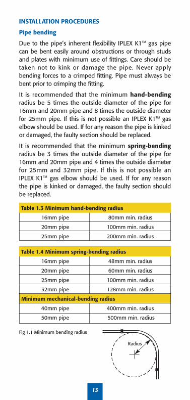
INSTALLATION PROCEDURES
Pipe bending
Due to the pipe’s inherent flexibility IPLEX K1TM gas pipecan be bent easily around obstructions or through studsand plates with minimum use of fittings. Care should betaken not to kink or damage the pipe. Never applybending forces to a crimped fitting. Pipe must always bebent prior to crimping the fitting.
It is recommended that the minimum hand-bendingradius be 5 times the outside diameter of the pipe for16mm and 20mm pipe and 8 times the outside diameterfor 25mm pipe. If this is not possible an IPLEX K1TM gaselbow should be used. If for any reason the pipe is kinkedor damaged, the faulty section should be replaced.
It is recommended that the minimum spring-bendingradius be 3 times the outside diameter of the pipe for16mm and 20mm pipe and 4 times the outside diameterfor 25mm and 32mm pipe. If this is not possible anIPLEX K1TM gas elbow should be used. If for any reasonthe pipe is kinked or damaged, the faulty section shouldbe replaced.
13
Table 1.3 Minimum hand-bending radius
16mm pipe 80mm min. radius
20mm pipe 100mm min. radius
25mm pipe 200mm min. radius
Table 1.4 Minimum spring-bending radius
16mm pipe 48mm min. radius
20mm pipe 60mm min. radius
25mm pipe 100mm min. radius
32mm pipe 128mm min. radius
Minimum mechanical-bending radius
40mm pipe 400mm min. radius
50mm pipe 500mm min. radius
Fig 1.1 Minimum bending radius
Radius

INSTALLATION PROCEDURES Continued
Clipping
In accordance with AS 5601, IPLEX K1TM composite pipeinstalled above ground shall be retained in position byclips at intervals complying with the table below:
Timber and metal framework
Holes drilled in studs or plate’s etc shall be accuratelysized to allow for longitudinal movement, thermalexpansion and contraction of the pipe.
In metal framework suitable grommets or a sleevemust be installed to minimize abrasion and physicaldamage to the pipe.
Note: Use of silicone and other such materials is notrequired and could be detrimental to the pipe.
Corrosive environment
As per the requirements of AS 5601 and/or LocalAuthority requirements, pipes and fittings installed ina potentially corrosive environment must beprotected, i.e. marine environments.
Protection from physical damage
As per the requirements of AS 5601 and/or LocalAuthority requirements, pipes and fittings must beprotected against physical damage. This includes, but isnot limited to, physical damage caused by exposure todirect sunlight, human activity, mechanical equipment,rodents or other animals. Installation is not permittedin caravans or marine crafts, as per AS 5601.
14
Table 1.5 The use of pipe clips
Nom. pipe diameter Horizontal or graded pipes Vertical pipes
16mm 1,000mm 1,000mm
20mm 1,250mm 1,250mm
25mm 1,500mm 1,500mm
32mm 2,000mm 2,000mm
40mm 2,000mm 2,000mm
50mm 2,000mm 2,000mm

INSTALLATION PROCEDURES Continued
When IPLEX K1TM pipe is installed above the ground,
it must be protected against degradation from exposure
to ultraviolet light. IPLEX recommends that the pipe
be lagged or sleeved, (refer to Local Authority Codes
and By-laws).
Pipe buried underground must be at least 450mm deep
and covered with marker tape, approximately 150mm
above the pipe. If the pipe is buried under a building,
there must be no joints in the pipe.
Chases, ducts or conduits
Pipes embedded in walls or floors must comply with the
requirement of the appropriate building authority or
local regulations.
Thermal expansion
As the lineal thermal expansion rate of IPLEX K1TM pipe
is approximately 2.5mm for every 10°C temperature
change for each 10 metres of pipe, care must be taken
with the installation to allow for this potential
movement of the pipe. IPLEX K1TM pipe should not be
pulled tight between fixed points as this will prohibit
movement if the pipe contracts, and result in excessive
tensile forces on joints and fittings.
Note:
Manufacturer’s label must be displayed near the meter
or LPG cylinder. The label needs to indicate the brand of
composite pipe, the location of the future extension tee
and contact details. The label must not be attached to
the meter or LPG cylinder as these may be exchanged.
15

16
SIZING TABLES FOR CRIMP FITTINGS (Natural Gas)Flow through PE-HD/AL/PE-HD Composite Pipe Crimped Fittings (MJ/h)
Low PressurePressure Drop 0.075kPa (Meter Pressure 1.1kPa) K1Nom. Length of straight pipe in metresSize 2 4 6 8 10 12 14 16 18
16mm 84 58 46 40 35 32 29 26 2320mm 168 116 93 80 70 64 59 55 5125mm 328 226 181 155 138 125 115 107 10032mm 660 454 364 312 276 250 230 214 20140mm 1620 1064 838 700 615 553 503 467 43450mm 2973 1942 1518 1273 1114 997 906 838 779
20 25 30 35 40 45 50 55 6016mm 21 17 14 12 11 9 8 8 720mm 48 43 39 35 30 27 24 22 2025mm 95 84 76 70 65 61 58 55 5232mm 190 168 153 140 131 123 116 110 10540mm 408 355 320 290 270 253 236 223 21150mm 731 637 570 519 478 447 419 395 375
Low PressurePressure Drop 0.12kPa (Meter Pressure 1.25kPa) K1Nom. Length of straight pipe in metresSize 2 4 6 8 10 12 14 16 18
16mm 109 75 60 51 45 41 38 35 3320mm 217 149 120 103 91 82 76 70 6625mm 424 291 234 200 177 161 148 138 12932mm 851 585 470 402 356 323 297 276 25940mm 2090 1372 1080 903 794 713 649 602 56050mm 3835 2505 1959 1642 1438 1286 1169 1081 1005
20 25 30 35 40 45 50 55 6016mm 31 27 22 19 17 15 13 12 1120mm 62 55 50 46 43 40 38 35 3225mm 122 108 98 90 84 79 74 71 6732mm 245 217 197 181 168 158 149 142 13540mm 527 458 413 374 349 327 305 287 27250mm 943 822 735 670 617 577 540 510 484
High PressurePressure Drop 0.25kPa (Meter Pressure 2.75kPa) K1Nom. Length of straight pipe in metresSize 2 4 6 8 10 12 14 16 18
16mm 161 111 89 76 68 61 56 52 4920mm 323 222 178 153 135 122 113 105 9825mm 629 433 348 298 264 239 220 205 19232mm 1267 871 699 598 530 480 442 411 38640mm 2930 1899 1474 1232 1058 948 865 799 73050mm 5299 3573 2837 2417 2103 1899 1741 1624 1492
Note: Every fitting used within IPLEX K1TM system, includingtees, elbows, reducers, meter connections, and applianceconnections has an equivalence equal to 2.5 metres of pipe.

17
SIZING TABLES FOR CRIMP FITTINGS (Natural Gas)Flow through PE-HD/AL/PE-HD Composite Pipe Crimped Fittings (MJ/h)
High PressurePressure Drop 0.25kPa (Meter Pressure 2.75kPa) K1Nom. Length of straight pipe in metresSize 20 25 30 35 40 45 50 55 60
16mm 46 41 37 34 32 30 28 26 2320mm 93 82 75 69 64 60 57 54 5125mm 181 161 146 134 125 117 110 105 10032mm 364 323 293 269 250 235 222 211 20140mm 689 598 537 479 442 411 386 359 34350mm 1417 1248 1132 1013 950 891 846 787 752
High Pressure (Vic, SA, Qld, Tas and NT).Pressure Drop 0.75kPa (Meter Pressure 2.75kPa) K1Nom. Length of straight pipe in metresSize 2 4 6 8 10 12 14 16 18
16mm 292 201 161 138 122 111 102 95 8920mm 585 402 323 276 245 222 204 190 17825mm 1142 785 630 539 478 433 398 371 34832mm 2295 1577 1267 1084 961 871 801 745 69940mm 5303 3438 2668 2229 1915 1717 1565 1446 132150mm 9591 6467 5135 4375 3806 3437 3151 2940 2701
20 25 30 35 40 45 50 55 6016mm 84 75 68 62 58 54 51 49 4620mm 168 149 135 124 116 109 103 97 9325mm 328 291 264 243 226 212 200 190 18132mm 660 585 530 488 454 426 402 382 36440mm 1247 1082 972 867 800 745 699 649 62050mm 2564 2260 2049 1833 1720 1612 1531 1424 1362
High Pressure (NSW, WA)Pressure Drop 1.50kPa (Meter Pressure 2.75kPa) K1Nom. Length of straight pipe in metresSize 2 4 6 8 10 12 14 16 18
16mm 426 292 235 201 178 161 148 138 13020mm 851 585 470 402 356 323 297 276 25925mm 1661 1142 917 785 695 630 580 539 50632mm 3339 2295 1843 1577 1398 1267 1165 1084 101740mm 7742 5019 3896 3255 2795 2506 2285 2112 192850mm 14003 9442 7497 6388 5557 5018 4600 4293 3944
20 25 30 35 40 45 50 55 6016mm 122 109 98 90 84 79 75 71 6820mm 245 217 197 181 168 158 149 142 13525mm 478 424 384 353 328 308 291 276 26432mm 961 851 772 710 660 620 585 556 53040mm 1820 1579 1418 1266 1168 1087 1021 948 90550mm 3743 3299 2992 2676 2511 2354 2235 2079 1988
Note: Every fitting used within IPLEX K1TM system, includingtees, elbows, reducers, meter connections, and applianceconnections has an equivalence equal to 2.5 metres of pipe.

SIZING TABLES FOR CRIMP FITTINGS (LPG)Flow through PE-HD/AL/PE-HD Composite Pipe Crimped Fittings (MJ/h)
LPGPressure Drop 0.25kPa (Meter Pressure 2.75kPa) K1Nom. Length of straight pipe in metresSize 2 4 6 8 10 12 14 16 18
16mm 277 190 153 131 116 105 97 90 8420mm 554 381 306 262 232 210 193 180 16925mm 1081 743 597 511 453 410 377 351 32932mm 2173 1494 1199 1027 910 824 758 706 66240mm 4570 2963 2300 1921 1650 1479 1349 1247 113850mm 8266 5574 4426 3771 3281 2962 2716 2534 2328
20 25 30 35 40 45 50 55 6016mm 80 71 64 59 55 51 49 46 4420mm 159 141 128 118 110 103 97 92 8825mm 311 276 250 230 214 201 189 180 17232mm 625 554 502 462 430 403 381 362 34540mm 1075 932 837 747 690 642 603 560 53550mm 2210 1948 1766 1580 1482 1389 1320 1227 1174
LPGPressure Drop 10.0kPa (Meter Pressure 70.0kPa) K1Nom. Length of straight pipe in metresSize 2 4 6 8 10 12 14 16 18
16mm 2648 1820 1462 1251 1109 1005 924 860 80720mm 5297 3640 2923 2502 2218 2009 1848 1720 161425mm 10337 7104 5705 4883 4327 3921 3607 3356 314932mm 20779 14281 11468 9815 8699 7882 7251 6746 633040mm 43691 28325 21987 18368 15775 14144 12897 11919 1088150mm 79025 53284 42309 36052 31363 28318 25960 24225 22257
20 25 30 35 40 45 50 55 6016mm 762 675 612 563 524 491 464 441 42120mm 1524 1351 1224 1126 1048 983 928 882 84125mm 2974 2636 2388 2197 2044 1918 1812 1721 164232mm 5979 5299 4801 4417 4109 3856 3642 3459 330040mm 10273 8912 8005 7146 6594 6134 5761 5351 511050mm 21125 18619 16885 15101 14170 13283 12614 11732 11222
18
Note: Every fitting used within IPLEX K1TM system, includingtees, elbows, reducers, meter connections, and applianceconnections has an equivalence equal to 2.5 metres of pipe.

PIPE SIZING EXAMPLE
The following example uses Natural Gas with a MeterPressure of 2.75kPa with a Pressure Drop of 0.75kPa.(Refer page 17).
Step 1 – Add the mega joule rating of all the appliances (190+ 30+70) = 290MJ/h
• Refer to IPLEX Gas Sizing Tables to calculate the pipe sizeof the longest run:
A-B + B-C + C-D (13 + 10 + 8) = 31m (No fitting allowance required)
• Look up the table at the next highest length value =35m• Look for mega joule rating of the appliance (290 MJ/h) • Calculate pipe size = 32mm• Apply this pipe size to (A-B) = 32mm
Step 2 – Calculate the length of each run:
For the hot water service the calculations are: A-B + B-F (13 + 4) = 17m
• Multiply the number of fittings (3) x the fitting equivalence(refer IPLEX Pipe Sizing Tables) 3 x 2.5 = 7.5m
• Add the run length to the fitting allowance: 17m + 7.5m = 24.5m
• Look up the table at the next highest length value = 25m• Look for mega joule rating of the appliance (190 MJ/h)• Calculate pipe size = 25mm• Apply this pipe size to (B-F) = 25mm
Step 3 – Repeat the above for each run:
For the run B-C, the calculations are: A-B + B-C = (13 + 10) = 23m
• Multiply the number of fittings (3) x the fitting equivalence(refer Iplex Pipe Sizing Tables) 3 x 2.5 = 7.5m
• Add the run length to the fitting allowance: 23m + 7.5m = 30.5m
• Look up the table at the next highest length value = 35m• Add the mega joule value of the remaining 2 appliances
(cooktop and space heater) = (100 MJ/h), • Calculate pipe size = 20mm• Apply this pipe size to (B-C) = 20mm
19

PIPE SIZING EXAMPLE (continued)
For the cooktop the calculations are: A-B + B-C + C-E (13 + 10 + 6) = 29m
• Multiply the number of fittings (4) x the fittingequivalence (refer Iplex Pipe Sizing Tables) 4 x 2.5 = 10m
• Add the run length to the fitting allowance: 29m + 10m = 39m
• Look up the table at the next highest length value = 40m• Look for mega joule rating of the appliance (30 MJ/h)• Calculate pipe size = 16mm• Apply this pipe size to (C-E) = 16mm
For the space heater the calculations are:A-B + B-C + C-D (13 + 10 + 8) = 31m
• Multiply the number of fittings (4) x the fittingequivalence (refer Iplex Pipe Sizing Tables) 4 x 2.5 = 10m
• Add the run length to the fitting allowance: 31m + 10m = 41m
• Look up the table at the next highest length value = 45m• Look for mega joule rating of the appliance (70 MJ/h)• Calculate pipe size = 20mm• Apply this pipe size to (C-D) = 20mm
Table below indicates what pipe size should be used foreach run.
20
A. Gas Meter2.75 kpa
Natural Gas
F. Hot WaterService
190 MJ/hD. SpaceHeater
70 MJ/h
E. Cooktop30 MJ/h
13m
BC10m 2m4m
6m
6m
Pipe Gas Flow Nominal No. of Length of Section MJ/h Size (DN) Fittings Used Run (m)
A-B 290 32 mm na 31 m
B-C 100 20 mm 3 30.5 m
C-D 70 20 mm 4 41 m
C-E 30 16 mm 4 39 m
B-F 190 25 mm 3 24.5 m

21
PRODUCT RANGEMinimum
Product Iplex Code Order DescriptionQuantity
K1TM COMPOSITE PIPEFK11650 1 16mm x 50 metre coil K1FK12050 1 20mm x 50 metre coil K1FK12550 1 25mm x 50 metre coil K1FK13225 1 32mm x 25 metre coil K1FK116E 25 16mm x 5 metre length K1FK120E 15 20mm x 5 metre length K1FK125E 10 25mm x 5 metre length K1FK132E 5 32mm x 5 metre length K1FK140E 5 40mm x 5 metre length K1FK150E 4 50mm x 5 metre length K1
DUCTING PIPEFK29300022 1 50m coil to suit 16mm
and 20mm PipeFK29300024 1 50m coil to suit 25mm PipeFK132DUC 1 10m coil to suit 32mm PipeDU5020 1 20m coil to suit 40mm
and smaller pipeDU6520 1 20m coil to suit 50mm
and smaller pipe
STRAIGHT JOINERFK1501616 10 16mm K1FK1502020 5 20mm K1FK1502525 5 25mm K1FK1503232 5 32mm K1FK1504040 1 40mm K1FK1505050 1 50mm K1
REDUCING JOINERFK1512016 5 20mm-16mm K1FK1512516 5 25mm-16mm K1FK1512520 5 25mm-20mm K1FK1513220 5 32mm-20mm K1FK1513225 5 32mm-25mm K1FK1514032 1 40mm-32mm K1FK1515032 1 50mm-32mm K1FK1515040 1 50mm-40mm K1
MALE ADAPTORFK1521615 10 16mm K1 x 15mm BSP FK1522015 10 20mm K1 x 15mm BSP FK1522020 5 20mm K1 x 20mm BSP FK1522520 5 25mm K1 x 20mm BSP FK1522525 5 25mm K1 x 25mm BSP FK1523220 5 32mm K1 x 20mm BSP FK1523225 5 32mm K1 x 25mm BSP FK1523232 5 32mm K1 x 32mm BSP FK1524032 1 40mm K1 x 32mm BSP FK1525040 1 50mm K1 x 40mm BSP
FEMALE ADAPTORFK1531615 10 16mm K1 x 15mm BSP FK1531620 10 16mm K1 x 20mm BSP FK1532020 5 20mm K1 x 20mm BSP FK1532520 5 25mm K1 x 20mm BSP FK1533225 5 32mm K1 x 25mm BSP FK1533232 5 32mm K1 x 32mm BSP FK1534040 5 40mm K1 x 40mm BSP FK1535050 5 50mm K1 x 50mm BSP
EQUAL BENDS – 90°FK1579016 10 16mm bend K1FK1579020 5 20mm bend K1FK1579025 5 25mm bend K1FK1579032 5 32mm bend K1FK1579040 1 40mm bend K1FK1579050 1 50mm bend K1

22
PRODUCT RANGE ContinuedMinimum
Product Iplex Code Order DescriptionQuantity
MALE BEND – 90°FK1581615 10 16mm K1 x 15mm BSPFK1582020 5 20mm K1 x 20mm BSPFK1582025 5 20mm K1 x 25mm BSPFK1582525 5 25mm K1 x 25mm BSPFK1583225 5 32mm K1 x 25mm BSP
WINGBACK ELBOW (MALE Lugged)FK1601615P 5 16mm K1 x 15mm BSP FK1601615 5 16mm K1 x 15mm BSP FK1601615100 5 16mm K1 x 15mm BSP x 100mmFK1602015 5 20mm K1 x 15mm BSP FK1602015100 5 20mm K1 x 15mm BSP x 100mmFK1602015180 1 20mm K1 x 15mm BSP x 180mmFK1602015200 5 20mm K1 x 15mm BSP x 200mmFK1602020 5 20mm K1 x 20mm BSP FK1602020200 5 20mm K1 x 20mm BSP x 200mm
WINGBACK ELBOW (FEMALE)FK1591615L 10 16mm K1 x 15mm BSP LuggedFK1592015L 5 20mm K1 x 15mm BSP LuggedFK1592020L 5 20mm K1 x 20mm BSP LuggedFK1592520L 5 25mm K1 x 20mm BSP Lugged
EQUAL TEESFK155161616 10 16mm x 16mm x 16mm K1FK155202020 5 20mm x 20mm x 20mm K1FK155252525 5 25mm x 25mm x 25mm K1FK155323232 5 32mm x 32mm x 32mm K1FK155404040 1 40mm x 40mm x 40mm K1FK155505050 1 50mm x 50mm x 50mm K1
REDUCING TEESFK156162016 5 16mm x (20mm) x 16mm K1FK156201616 5 20mm x (16mm) x 16mm K1FK156201620 5 20mm x (16mm) x 20mm K1FK156202016 5 20mm x (20mm) x 16mm K1FK156252020 5 25mm x (20mm) x 20mm K1FK156252025 5 25mm x (20mm) x 25mm K1FK156252520 5 25mm x (25mm) x 20mm K1FK156322032 5 32mm x (20mm) x 32mm K1FK156322525 5 32mm x (25mm) x 25mm K1FK156322532 5 32mm x (25mm) x 32mm K1FK156402540 1 40mm x (25mm) x 40mm K1FK156403232 1 40mm x (32mm) x 32mm K1FK156404032 1 40mm x (40mm) x 32mm K1FK156502550 1 50mm x (25mm) x 50mm K1FK156504040 1 50mm x (40mm) x 40mm K1FK156505032 1 50mm x (50mm) x 32mm K1FK156505040 1 50mm x (50mm) x 40mm K1
(denotes branch size)
FUTURE EXTENSION TEEFK18016 10 16mm Male Threaded TeeFK18020 5 20mm Male Threaded TeeFK18025 5 25mm Male Threaded TeeFK18032 1 32mm Male Threaded TeeFK18040 1 40mm Male Threaded TeeFK18050 1 50mm Male Threaded Tee

23
PRODUCT RANGE ContinuedMinimum
Product Iplex Code Order DescriptionQuantity
GAS METER CONNECTOR (330mm long)FK1892025 1 20mm K1 x 25mm BSPFI FK1892525 1 25mm K1 x 25mm BSPFI FK1893225 1 32mm K1 x 25mm BSPFI FK1892020 1 20mm K1 x 20mm BSPFI FK1892520 1 25mm K1 x 20mm BSPFI FK1893220 1 32mm K1 x 20mm BSPFI
BRAZING TAILSFK1731615 30 16mm K1 x 15mm CU FI FK1732015 20 20mm K1 x 15mm CU FI FK1732020 20 20mm K1 x 20mm CU FI FK1732520 5 25mm K1 x 20mm CU FI FK1732525 10 25mm K1 x 25mm CU FI FK1733232 10 32mm K1 x 32mm CU FI FK1734040 1 40mm K1 x 40mm CU FI FK1735050 1 50mm K1 x 50mm CU FI
K1TM TO FLARED COPPER CONNECTORFK1541615 10 16mm K1 x 15mm BSPFK1542015 5 20mm K1 x 15mm BSPFK1542020 5 20mm K1 x 20mm BSPFK1542025 5 20mm K1 x 25mm BSPFK1542525 5 25mm K1 x 25mm BSP
TEST PLUGS FK1TP16 50 16mm K1 FK1TP20 20 20mm K1 FK1TP25 20 25mm K1 FK1TP32 10 32mm K1 FK1TP40 1 40mm K1 FK1TP50 1 50mm K1
CRIMP RINGSFK1CRING16 50 16mm Crimp Ring K1FK1CRING20 50 20mm Crimp Ring K1FK1CRING25 25 25mm Crimp Ring K1FK1CRING32 25 32mm Crimp Ring K1FK1CRING40 1 40mm Crimp Ring K1FK1CRING50 1 50mm Crimp Ring K1
16mm CLIPSFK29016TK 100 16mm with TEK ScrewFK29016TS 100 16mm with Twist Shank NailFK29016M 100 16mm with Masonry NailFK29016ACM2 100 16mm with Masonry Anchor
20mm CLIPSFK29020TK 100 20mm with TEK ScrewFK29020TS 100 20mm with Twist Shank NailFK29020M 100 20mm with Masonry NailFK29020ACM4 100 20mm with Masonry Anchor
25mm CLIPSFK29025TK 100 25mm with TEK ScrewFK29025TS 100 25mm with Twist Shank NailFK29025M 100 25mm with Masonry Nail

24
TOOLS
Product Iplex Code Description
REMS AKKU TOOL & ACCESSORIESREMSAKKUTOOL REMS AKKU Crimping Tool
with Li-ion BatteryREMSAKKUTOOLKIT REMS AKKU Crimping Tool with Li-ion
Battery (c/w K40 & K50 heads}REMSBATTERY REMS Battery NI-CD (for old-style tool)REMSCRIMP16 16mm REMS K1/K2/P18 Crimp JawREMSCRIMP20 20mm REMS K1/K2 Crimp JawREMSCRIMP25 25mm REMS K1/K2 Crimp JawREMSCRIMP32 32mm REMS K1/K2 Crimp JawREMSCRIMP40 40mm REMS K1/K2 Crimp JawREMSCRIMP50 50mm REMS K1/K2 Crimp Jaw
REMS MINI TOOL & ACCESORIESREMMINITOOL REMS Mini Press Crimping Tool
with Li-ion Battery REMMINITOOLKIT REMS Mini Press Crimping Tool with
Li-ion Battery (c/w K16 & K20 heads)REMSMINIBATTERY REMS Mini Battery Li-ion 1.3AHREMSMINICHARGER REMS Mini Li-ion/NI-CD Rapid ChargerREMSMINICRIMP16 16mm REMS K1/K2/P18 Crimp JawREMSMINICRIMP20 20mm REMS K1/K2 Crimp JawREMSMINICRIMP25 25mm REMS K1/K2 Crimp JawREMSMINICRIMP32 32mm REMS K1/K2 Crimp JawREMSMINICRIMP40 40mm REMS K1/K2 Crimp Jaw
I-PRESS MINI TOOL & ACCESSORIESIPRESSTOOL I-Press Mini Press Crimp Tool
with Li-ion BatteryIPRESSTOOLKIT I-Press Mini Press Crimp Tool with
Li-ion Battery (c/w K16 & K20 heads)IPRESSBATTERY I-Press Mini Battery Li-ion 18VIPRESSCHARGER I-Press Mini ChargerIPRESSCRIMP16 16mm I-Press K1/K2/P18 Crimp JawIPRESSCRIMP20 20mm I-Press K1/K2 Crimp JawIPRESSCRIMP25 25mm I-Press K1/K2 Crimp JawIPRESSCRIMP32 32mm I-Press K1/K2 Crimp Jaw
ALBA HAND TOOLPCR18 Hand Crimping ToolFKPCR20 Hand Crimping Tool 20mmFKCR25 Hand Crimping Tool 25mmFKCR32 Hand Crimping Tool 30mmCRIMPING TOOL REPLACEMENT PARTSALBAPARTS916 Contains:Cam bolt x/w M10 nyloc nutHandle pin c/w starlock washerOversize rollerPivot pin c/w E type clips
ROUNDING TOOLFK1RNDTOOL
Pipe Rounding Tool16mm, 20mm, 25mm and 32mm
PIPE CUTTERSREMSCUTTER63REMS Universal Pipe Cutting Tool for pipe up to 63mm
K203064700Pipe Cutting Tool
for 16mm, 20mm and 25mm
REMSPIPECUTTERPipe Cutting Tool for16mm–32mm

25
CUSTOMER’S NEEDS CHANGE...PIPE MATERIALS CHANGEAlong with the evolution of plastics pipe forhot and cold water plumbing IPLEX hasdeveloped a gas piping system that can beinstalled with the same ease as the verypopular Pro-fitTM and IPLEX K2TM systems.
CRIMPING ACCESSORIESMinimum
Product Iplex Code Order DescriptionQuantity
CRIMP GAUGEFKP64 1 K1Crimp Gauge
to suit 16mm, 20mm, 25mm and 32mm pipe.
FK4050 1 K1 Crimp Gaugeto suit 40mm and 50mm pipe.
K1 FIRE COLLARFK1COLLARF32 To suit 16-32mm PipeFK1COLLARF50 To suit 40-50mm Pipe
STICKER / METAL TAGFK1METALSTICKER 50 Meter Box Metal TagFK1STICKER 1 Pad (48) Meter Box Vinyl StickerComposite Pipe System for Gas.
The threaded connector for future extension is located:
..............................
..............................
..............................
..............................
.
Gas Fitter’s Name: ..............................
..............................
...............
Gas Licence No: ..............................
..............................
.....
Contact Iplex on 13 18 40
or visit our website at www.iplex.com.au
TM
This home is plumbed with
K1

26
FREQUENTLY ASKED QUESTIONSQ. Can IPLEX K1TM composite gas pipe and fittings be
used in ground?A. Yes, as fittings are DR (dezincification resistant) brass.Q. Can IPLEX K1TM composite gas pipe be used to connect
directly to the gas meter?A. Yes, providing any exposed pipe is lagged or sleeved
as the pipe is not UV resistant. Iplex has a number offittings available for such use.
Q. Can IPLEX K1TM composite gas pipe be chased inmasonry walls and floors?
A. Yes, the pipe can be chased into masonry walls with noprotection necessary.
Q. Can IPLEX K1TM composite gas pipe be embeddedin concrete?
A. Yes, the pipe can be embedded in concrete but cannotcontain any joints. Iplex recommends the pipe should besleeved for best practice.
Q. What warranty do I receive when I install IPLEX K1TM
composite gas system?A. When installed and used correctly for its intended
purpose, as specified in AS5601, National Gas InstallationCode and the Iplex Pipelines Installation Guide, IplexPipelines warrants K1TM against manufacturing defects fora period of 25 years from the date of manufacture.
Q. How close can IPLEX K1TM composite pipe be to highheat sources such as heating appliances and fluesfrom heating appliances?
A. IPLEX K1TM composite gas pipe should be kept at least500mm from such heat sources.
Q. What distance should pipe be from slow combustiontype stoves?
A. IPLEX K1TM composite gas pipe should be kept at least1500mm from such heat sources.
Q. What distance should IPLEX K1TM composite pipe bekept from recessed electric light fittings?
A. IPLEX K1TM composite gas pipe should be kept at least300mm from such light fittings.
Q. How close can IPLEX K1TM composite pipe be to gas orcentral heating vents or flues?
A. No closer than 150mm.Q. Can IPLEX K1TM composite pipe be used for the
final connection?A. No, however, with the use of transition fittings IPLEX K1TM
composite pipe can be used to connect to copper orsteel pipe.
Q. What is the maximum pressure IPLEX K1TM compositepipe can be operated at for Natural Gas and LPG?
A. 70kPa.

27
DISCLAIMERThe information contained in this document should serve as a guide only and issubject to change without notice. Iplex Pipelines Australia Pty Ltd does not inviteany person to act or rely upon such information and liability for such information isexcluded. In particular, as new technology is developed rapidly, productspecifications, designs and components may change and Iplex Pipelines AustraliaPty Ltd reserves the right at its discretion to make changes as it see fit. Theinformation contained in this document does not form part of the terms andconditions of sale or constitute the description of any goods to be supplied by IplexPipelines Australia Pty Ltd or its distributors. Before purchasing goods, customersshould source current product information from their distributor or seek expertadvice on their particular intended use and application for the product. No part ofthis document may be reproduced, stored in a retrieval system or transmitted inany form, electronic, mechanical recording or otherwise without the prior writtenconsent of Iplex Pipelines Australia Pty Ltd. The designs, graphics, logos,tradenames, trademarks and other intellectual property contained in this documentare either owned by Iplex Pipelines Australia Pty Ltd or used with the permission ofthe owner or licensee, and must not be used without prior written consent.Copyright ©2012 Iplex Pipelines Australia Pty Ltd. All rights reserved.
WARRANTY

IPLEX Pipelines Pty Limited. ABN 56 079 613 308Ph: 13 18 40 or fax 13 18 60
www.iplex.com.au
Version 3


