Amit Ramji – A4 – University of Hertfordshire Composite Lab Report Composite Testing Lab undertaken on 22 nd October 2013 Group E Amit Ramji 10241445 University of Hertfordshire - Aerospace Engineering Year 4 – Mechanics and Properties of Materials - 6ACM0003 30 th October 2013
Transcript
Amit Ramji – A4 – University of Hertfordshire
Composite Lab Report
Composite Testing Lab undertaken on 22nd October 2013
Group E
Amit Ramji 10241445
University of Hertfordshire - Aerospace Engineering
Year 4 – Mechanics and Properties of Materials - 6ACM0003
30th October 2013
Amit Ramji – A4 – University of Hertfordshire
Introduction Composites in engineering are an alternative solution to traditional materials, where man-made fibres and natural fibres are bonded into a matrix to provide overall directional strength, improved tensile and fatigue resistance due to the imperfection removal processing involved when creating fibres. Firstly the fibre volume ratios are the main consideration where one would investigate the overall area of fibres and volume of resin required to encapsulate the fibre into the matrix.[1] The next consideration is made toward the fibre length where a critical length is established by the use of small section analysis.[2] Further to fibre length are decisions made on alignment of fibres to the principal stress axis of the application in question, this involves detailed stress analysis based on geometry of the part and loading conditions. Later followed by configuring the laminate layup and fibre/multiple fibres of different materials and its resin/plastic matrix based on the stress and stiffness requirements of the application.
The Rule of Mixtures is a quick approach to determine the composite layup required for the particular application. It is generally a conservative approach which uses an estimate of 10% of the normalised composite strength in a direction of loading at angles to the principal stress axis using the composite strength from the idealised aligned loading.[3] This experimental investigation aims to verify the 10% Rule of Mixtures by physical testing of samples of differing layups of 16 ply’s of Carbon Fibre Reinforced Epoxy (CFRE-T800 / 0.4xEpoxy-924 & 0.6xCarbon Fibre).
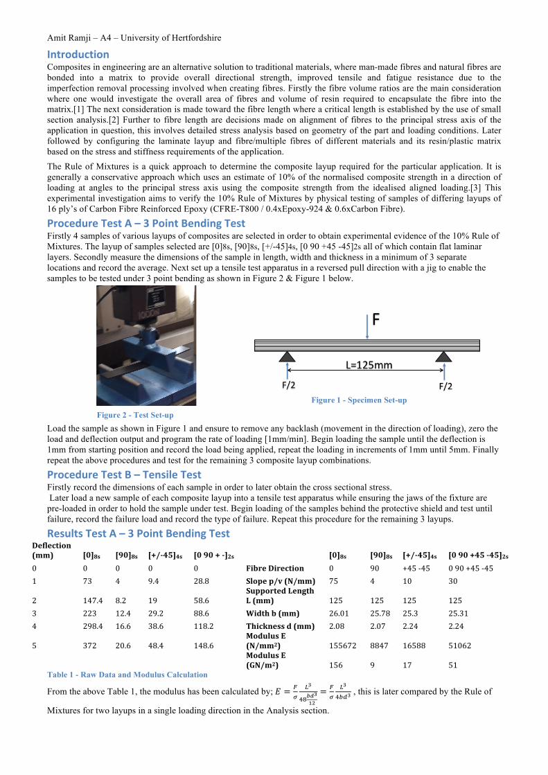
Procedure Test A – 3 Point Bending Test Firstly 4 samples of various layups of composites are selected in order to obtain experimental evidence of the 10% Rule of Mixtures. The layup of samples selected are [0]8s, [90]8s, [+/-45]4s, [0 90 +45 -45]2s all of which contain flat laminar layers. Secondly measure the dimensions of the sample in length, width and thickness in a minimum of 3 separate locations and record the average. Next set up a tensile test apparatus in a reversed pull direction with a jig to enable the samples to be tested under 3 point bending as shown in Figure 2 & Figure 1 below. Load the sample as shown in Figure 1 and ensure to remove any backlash (movement in the direction of loading), zero the load and deflection output and program the rate of loading [1mm/min]. Begin loading the sample until the deflection is 1mm from starting position and record the load being applied, repeat the loading in increments of 1mm until 5mm. Finally repeat the above procedures and test for the remaining 3 composite layup combinations.
Procedure Test B – Tensile Test Firstly record the dimensions of each sample in order to later obtain the cross sectional stress. Later load a new sample of each composite layup into a tensile test apparatus while ensuring the jaws of the fixture are pre-loaded in order to hold the sample under test. Begin loading of the samples behind the protective shield and test until failure, record the failure load and record the type of failure. Repeat this procedure for the remaining 3 layups.
Results Test A – 3 Point Bending Test Deflection(mm) [0]8s [90]8s [+/-‐45]4s [0 90 + -‐]2s
Discussion Experimental Errors: From the testing, it is conclusive that the Rule of Mixtures when used against test data is accurate and is generally conservative. Errors for the two layup’s and pull directions shown are minimal and is conclusively a fast approach to calculate alternative layups/loading directions based on application requirements. Errors such as the 8.9% found in the [+/-45]4s can be due to experimental errors in setting up the apparatus/sample, overshooting the deflection selection, sliding of the measurement device within the tensile test apparatus. An alternative may be to use strain gauges on a repeated investigation, which would provide a change in length at the extreme fibres, thus the stress and modulus can be calculated. Layup Inconsistency: The composite layup plays a significant factor for inconsistencies, however repeated tests would outline these errors. Manufacturing of composites involves layering of laminates in various fibre forms, which could leave pockets of air and impurities hence causing inter-laminar failure during loading. Conclusions: Using ABD matrices one can also see the same results as the test and 10% rule, however is a time consuming task and requires information on detailed material properties of the matrix and its fibre interaction. Overall the Rule of mixtures allows the composite designer to predict and size the composite based on the load requirements. Comparison to other materials: In comparison to other materials, composite solutions play an advantage in weight saving, as the strength can be directionally oriented to that of the principle stress axis. Fatigue resistance is also much greater and allows for manufacturing of components that usually could not be manufactured in single pieces. References [1] Messiry, M.E., Theoretical analysis of natural fiber volume fraction of reinforced composites. Alexandria Engineering
Journal, 2013. 52(3): p. 301-306. [2] McGrath, J.J. and J.M. Wille, Determination of 3D fiber orientation distribution in thermoplastic injection molding.
Composites Science and Technology, 1995. 53(2): p. 133-143. [3] Kim, H.S., On the rule of mixtures for the hardness of particle reinforced composites. Materials Science and Engineering: A,