Composite Structures Repair Development at KSC Sarah Cox NASA Materials and Process Engineering Kennedy Space Center, FL https://ntrs.nasa.gov/search.jsp?R=20150022491 2018-07-09T21:56:07+00:00Z
Supporting TeamPanel Fabrication, Repair Work, Testing - KSC• LaNetra Tate• Susan Danley • Anne Caraccio• Brian Cheshire• Jeffrey Sampson• Brian Taylor
NDE – PAR Systems, Inc• Bence Bartha • Jeff Elston
Modeling and Analysis – GSFC• Ken Segal• Babak Farrokh• Terry Fan
Agenda
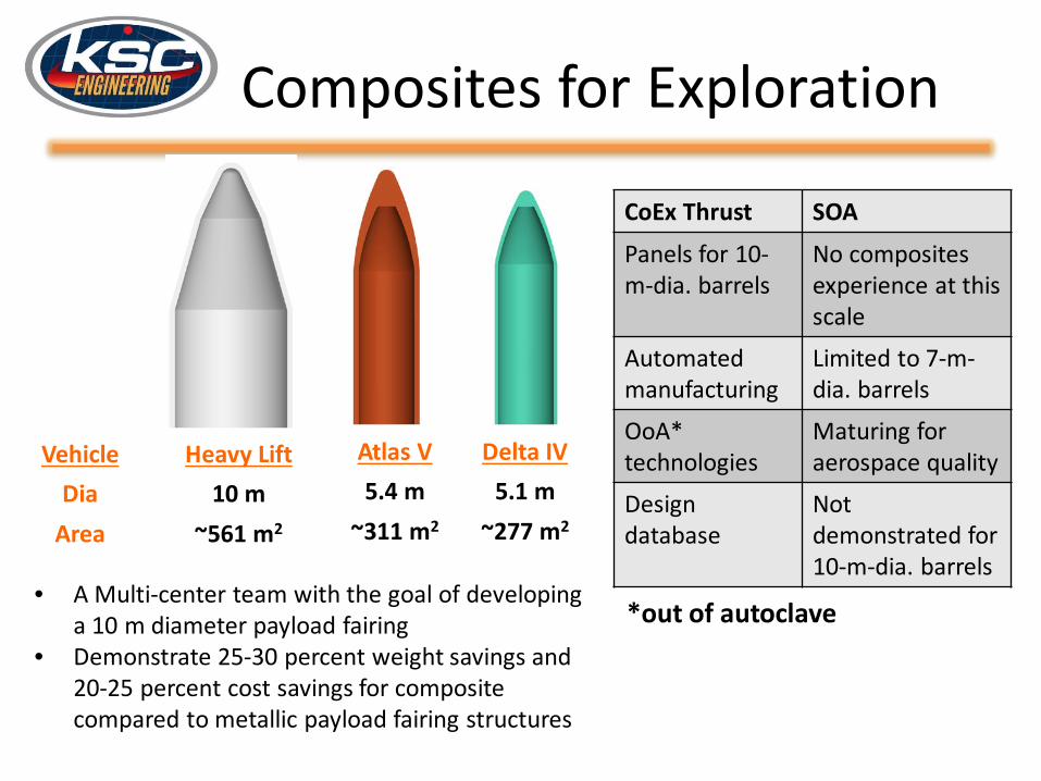
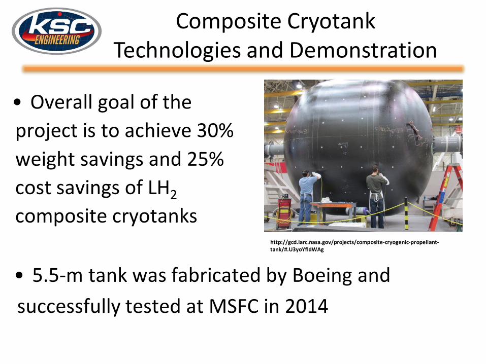
• Background of Composites and Recent Agency Composite Projects
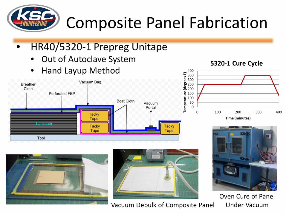
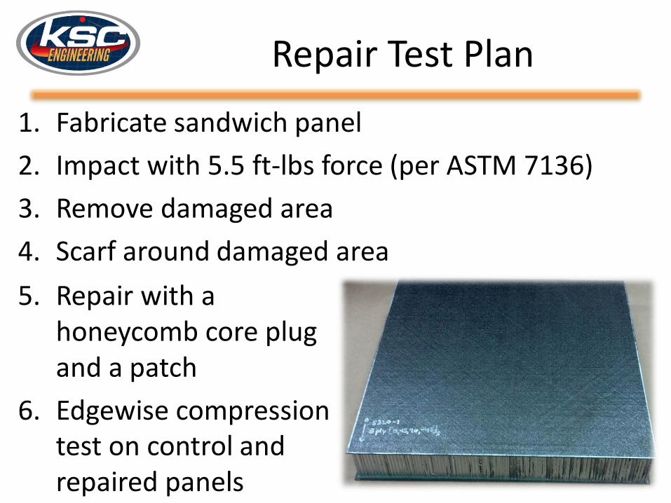
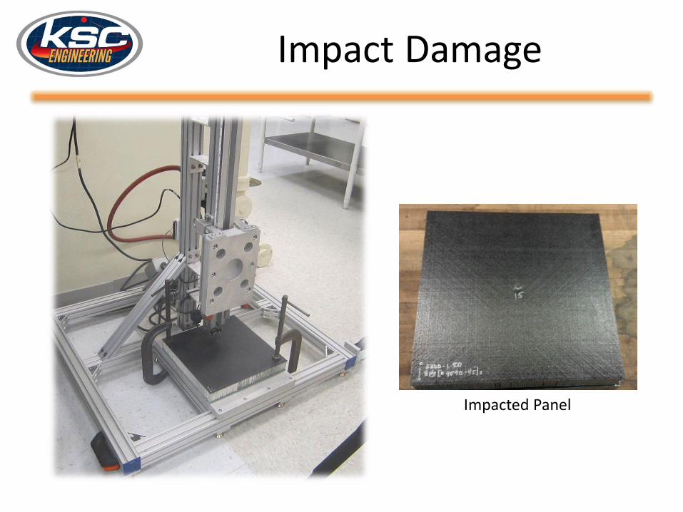
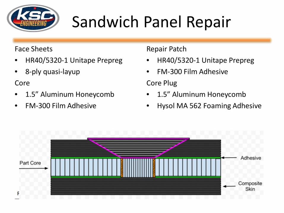
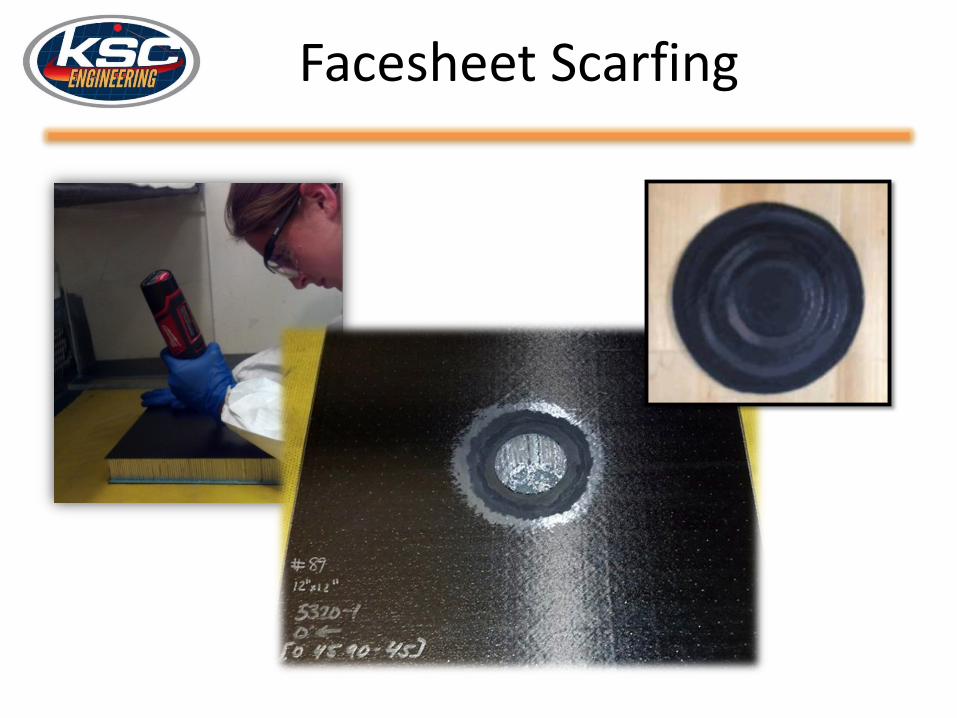
• Sandwich Panel Fabrication• Repair Development and Testing
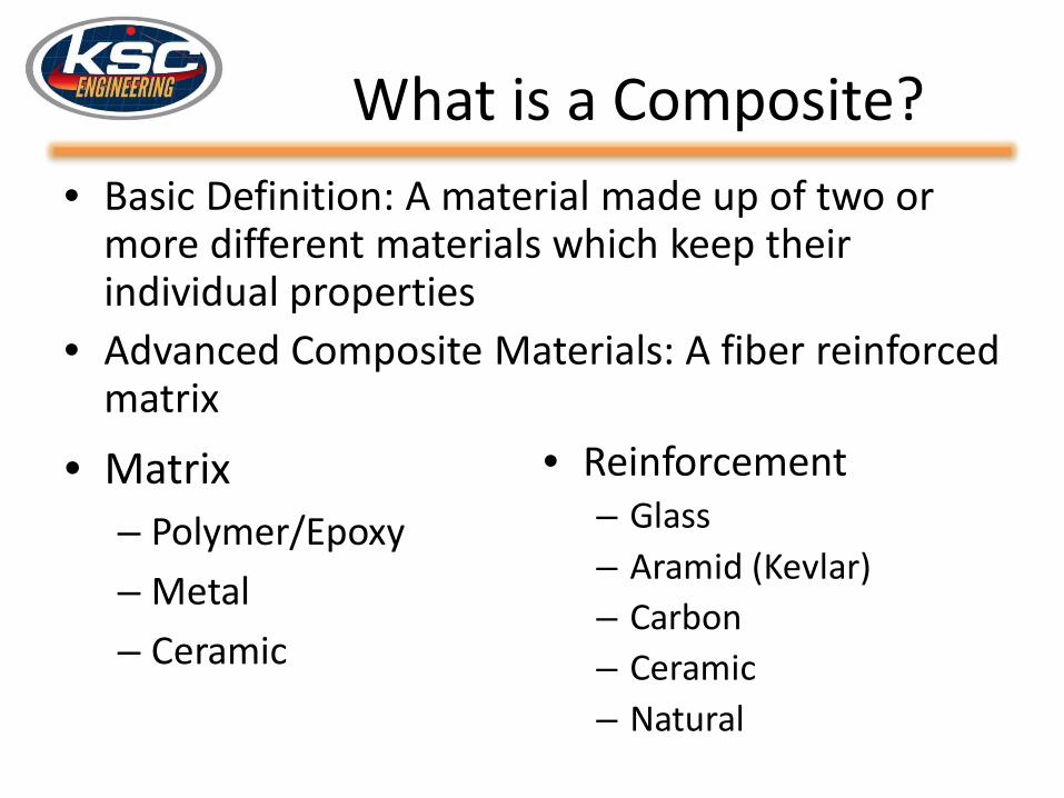
What is a Composite?• Basic Definition: A material made up of two or
more different materials which keep their individual properties
• Advanced Composite Materials: A fiber reinforced matrix
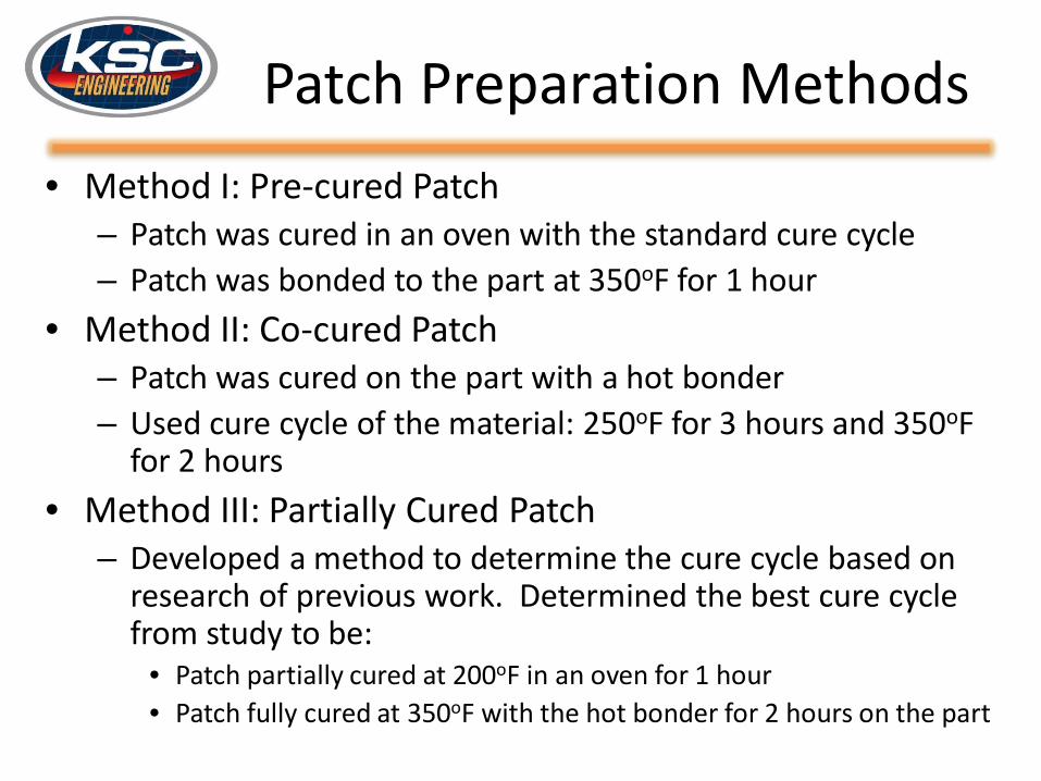
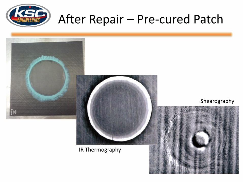
– Patch was cured in an oven with the standard cure cycle– Patch was bonded to the part at 350oF for 1 hour
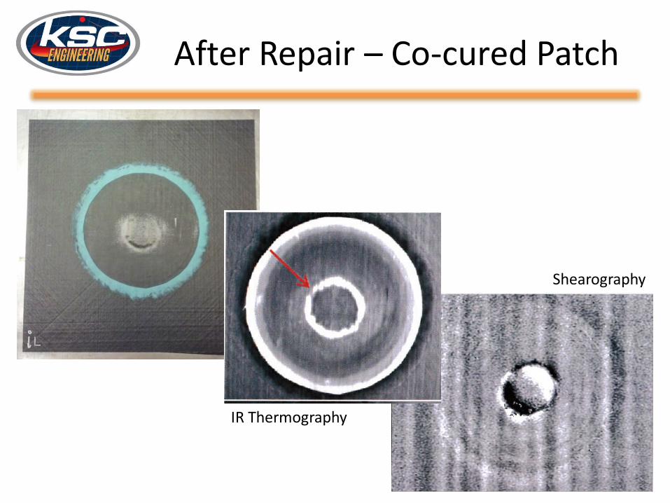
• Method II: Co-cured Patch– Patch was cured on the part with a hot bonder– Used cure cycle of the material: 250oF for 3 hours and 350oF
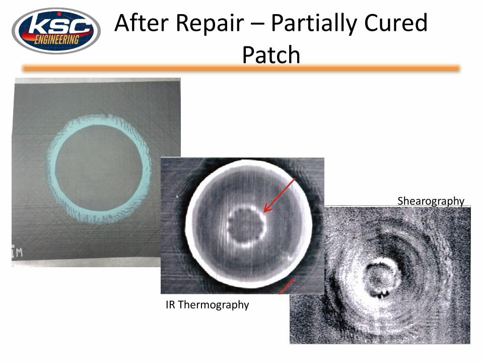
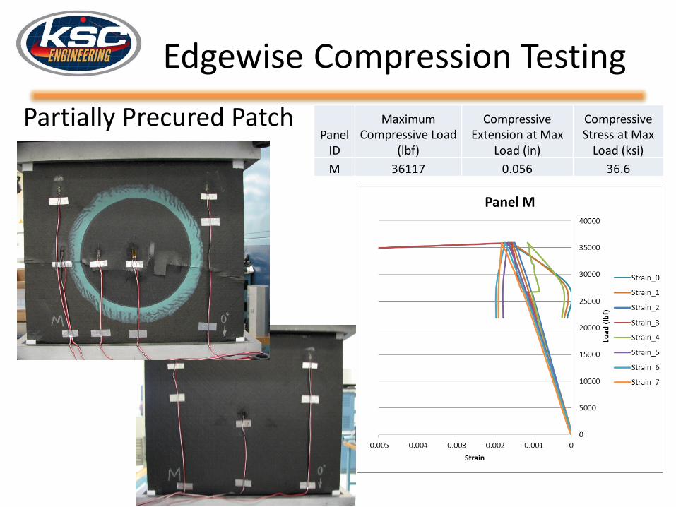
for 2 hours• Method III: Partially Cured Patch
– Developed a method to determine the cure cycle based on research of previous work. Determined the best cure cycle from study to be:
• Patch partially cured at 200oF in an oven for 1 hour• Patch fully cured at 350oF with the hot bonder for 2 hours on the part
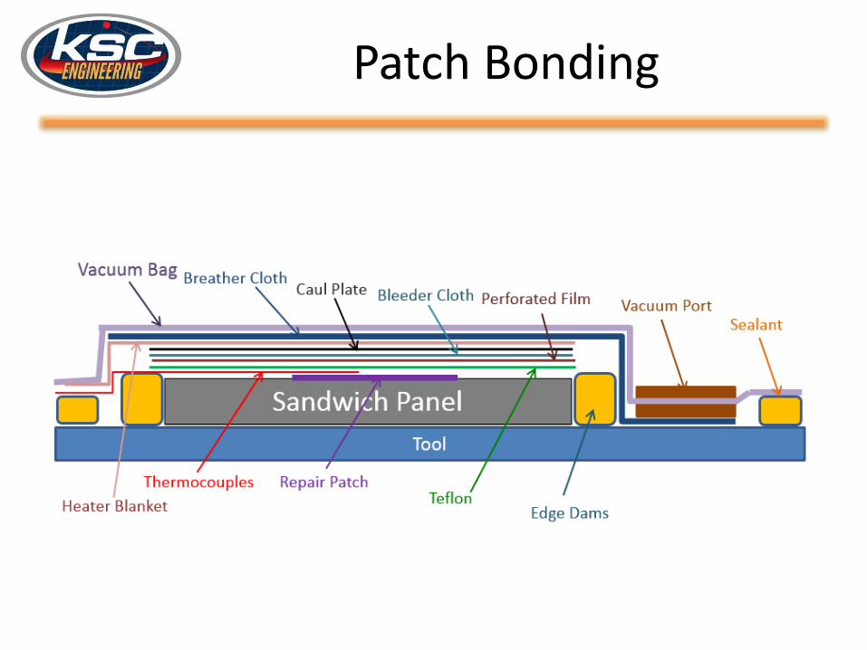
Patch Bonding
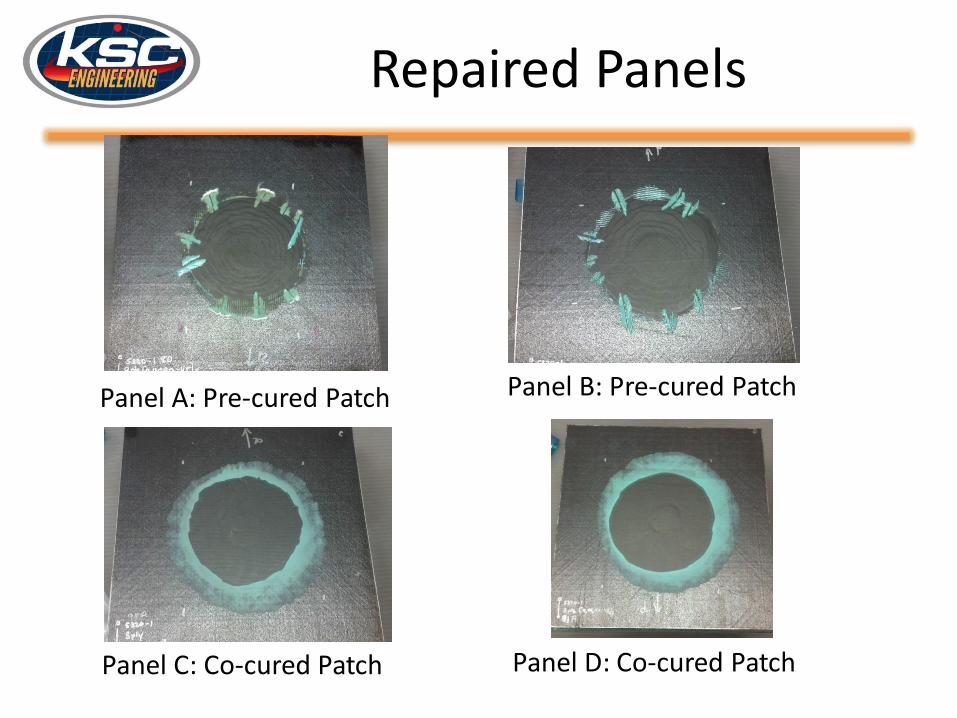
Repaired Panels
Panel D: Co-cured PatchPanel C: Co-cured Patch
Panel B: Pre-cured PatchPanel A: Pre-cured Patch
Edgewise Compression Testing
• ASTM C 364: Standard Test Method for Edgewise Compressive Strength of Sandwich Constructions• Assess the residual
strength • Panels potted into end caps to
prevent brooming• Edges wrapped to reduce
stress
Edgewise Compression Testing
Control (no damage, no repair)
Panel ID
Maximum Compressive Load
(lbf)
Compressive Extension at Max
Load (in)
Compressive Stress at Max
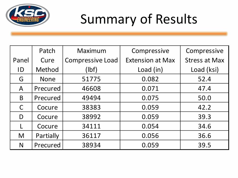
Load (ksi)G 51775 0.082 52.4H Error During Data Collection
Edgewise Compression Testing
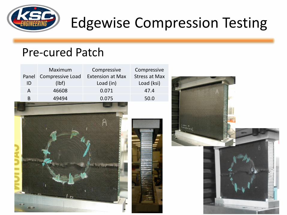
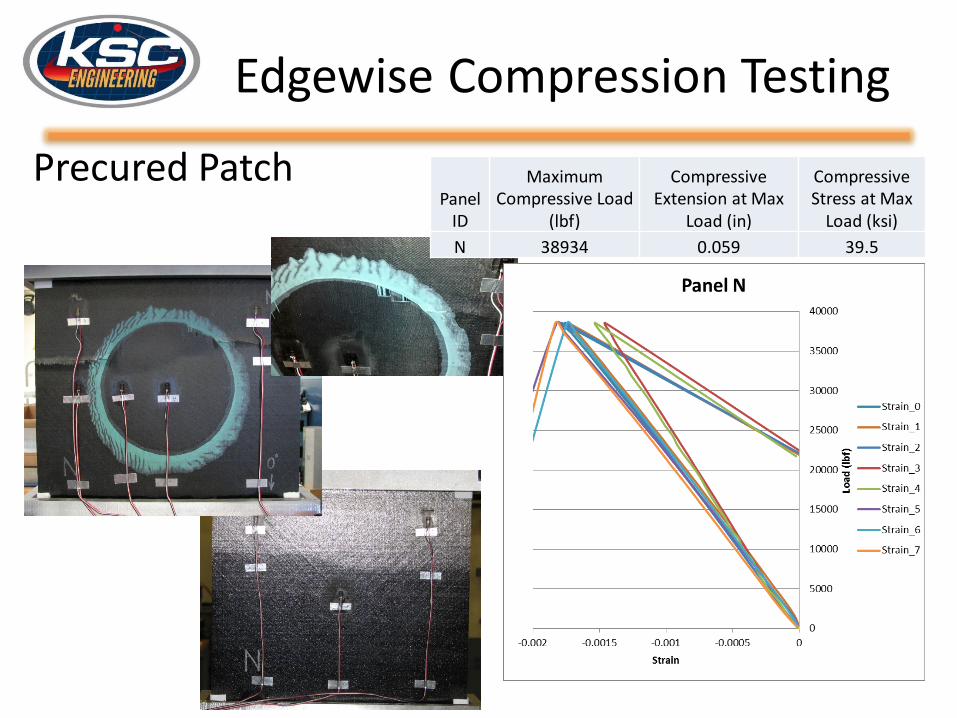
Pre-cured Patch
Panel ID
Maximum Compressive Load
(lbf)
Compressive Extension at Max
Load (in)
Compressive Stress at Max
Load (ksi)A 46608 0.071 47.4B 49494 0.075 50.0
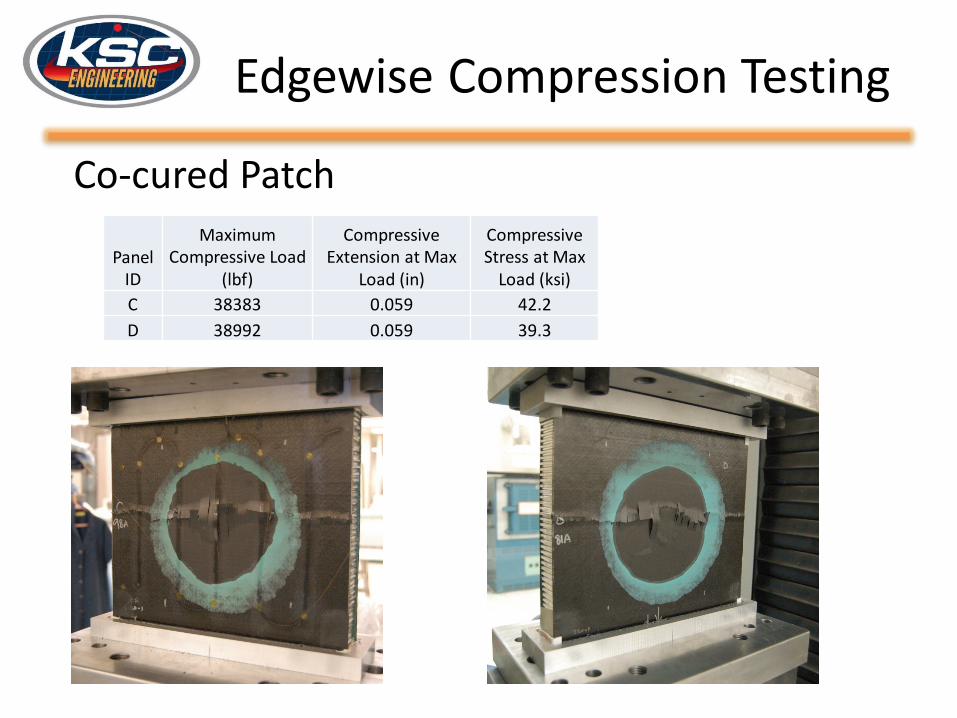
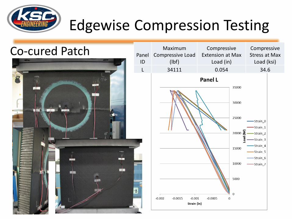
Edgewise Compression Testing
Co-cured Patch
Panel ID
Maximum Compressive Load
(lbf)
Compressive Extension at Max
Load (in)
Compressive Stress at Max
Load (ksi)C 38383 0.059 42.2D 38992 0.059 39.3
Partially Cured Patches
• Partially curing the patch in the oven allows the patch to have some rigidity and hold its shape but still have some flexibility to fully conform to the part
• Beneficial for curves and complex shapes• Decreases repair time by having commonly
damaged area shapes, and patch sizes available
• Decreases the cure time on the vehicle
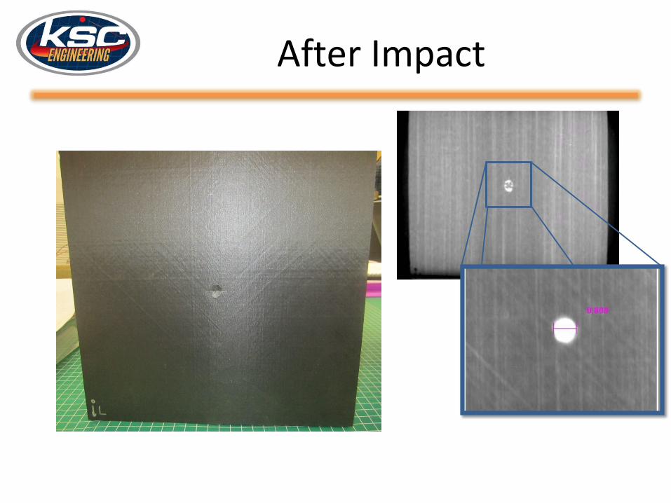
NDE during Repair Process
• Three additional sandwich panels were fabricated with the same materials
• The panels received IR Thermography scans after each event:– Fabrication– Impact– Repair (IR Thermography and Shearography)
• Three patch methods: pre-cured, co-cured, and partially cured patches used on the panels
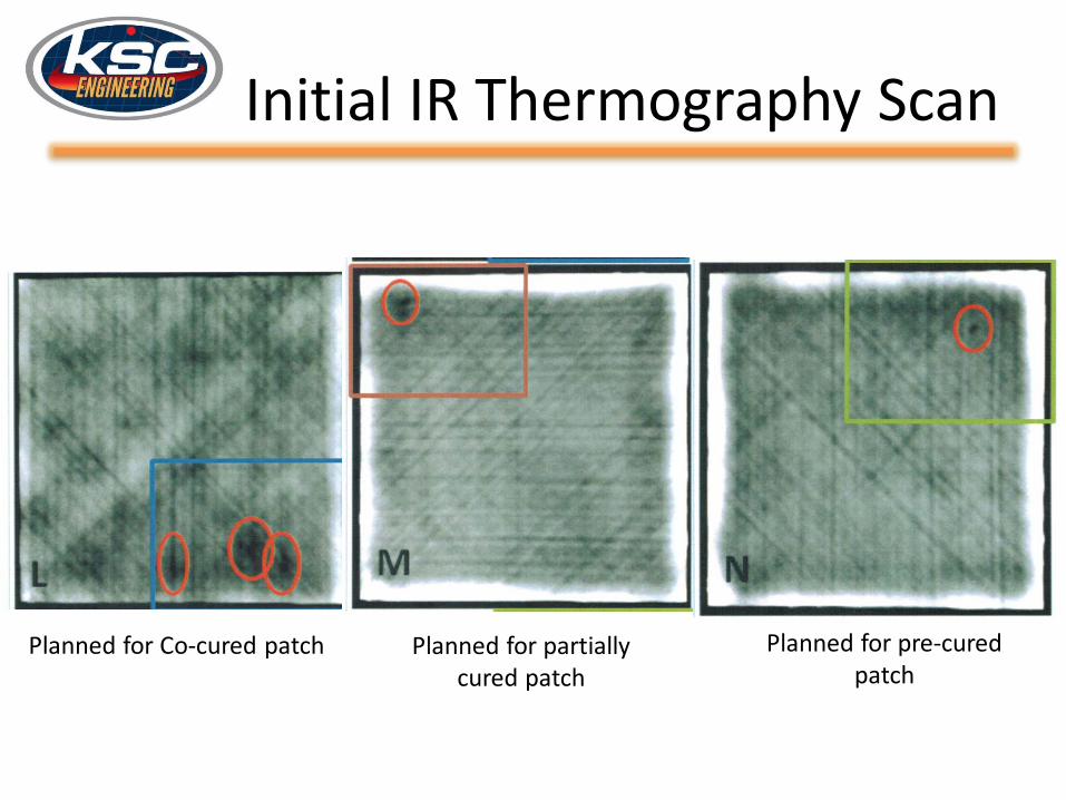
Initial IR Thermography Scan
Planned for Co-cured patch Planned for partially cured patch
• A comparative study of edgewise compression testing on repaired sandwich panels was completed
• Repairs with precured patches had higher loads than partially cured or cocured patches– This may be due to variations in hot bond curing– Need more data on partially cured patches
Future Work
• Test panels with damage, no repair• Test more panels with partial cure patches,
incorporating lessons learned from previous work
• Take a closer look at the heating profile of the hot bonder
• Perform repairs on curved panels
Questions?
References
1. Mark J. Shuart, “Composites for Exploration.” SAMPE Conference and Exhibition Presentation, PowerPoint. May 21-24, 2012
2. Douglas A. McCarville, et. al. (2013) “Manufacturing Overview of a 2.4 Meter Composite Cryotank.” SAMPE Conference Proceedings, Long Beach, CA, May 6-9, 2013.
3. Keller, R.L., Owen, W.S. “Process method to repair bismaleimide (BMI) composite structures.” (2004). US Patent Number 6761783. http://www.google.com/patents/US6761783
4. Keller, R.L. and Spalding, J.F. “Process development protocol and vacuum bag process for carbon-epoxy prepreg.” US Patent Number 7857925.https://www.google.com/patents/US7857925