85
Rotterdam, May, 2015 Composites in Infrastructure: impressions of design & calculation ir. Jan Peeters Director R&D / co-founder FiberCore FiberCore Europe, Rotterdam [email protected]

Rotterdam, May, 2015
Composites in Infrastructure:
impressions of design & calculation
ir. Jan Peeters Director R&D / co-founder FiberCore
FiberCore Europe, Rotterdam [email protected]
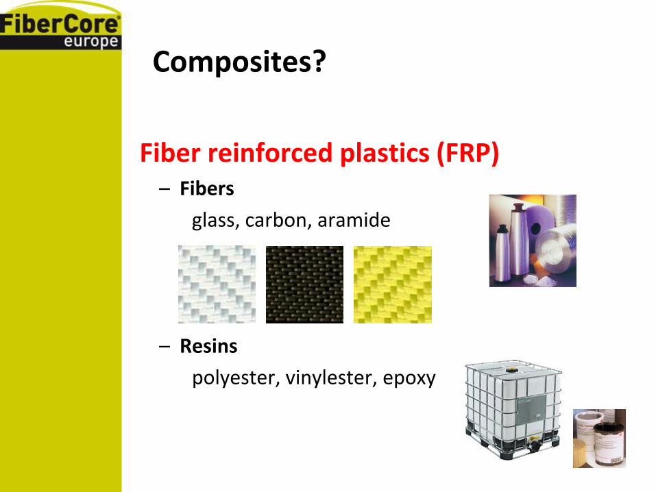
Composites?
Fiber reinforced plastics (FRP) – Fibers
glass, carbon, aramide
– Resins
polyester, vinylester, epoxy

Production processes for FRP

Raw material comparison

E/(ρ*g)
σ/(ρ*g)
Mild steel
(0,5;2,75)
Specific properties

Carbon fibers

Stress
Strain
steel 360 MPa
0,2%
Assume: sandwich with steel skins
Width B
Depth H
Wall thickness t
Wall thickness t
Designed for strength: UC = 1
Bending stiffness EI
210 GPa
34 GPa
composite 0/90ᵒ, 75/25% 600 MPa
2% 0
Assume: sandwich with composite skins
Same EI wall thickness 6,64 t
Wall thickness 6,64 t
Wall thickness 6,64 t
UC on strength: 0,1 ; safety margin 10
Depth H
Width B
Use
in bridge
Composites: stiffness dominated designs

Example bridge design
• Assume linear elasticity
• Assume beam behaviour
• Assume three-point-bending
• Design for stiffness (usability limit state)

Max. deflection of the beam
umax
5
384qL L
4
EI
1
8qL L
2
GA
F
2
L
2
3
3 EI
1
4F L
GA
In steel:
umax
5
384qL L
4
EI
F
2
L
2
3
3 EI
In composite:
in which EI = bending stiffness, GA = shear stiffness
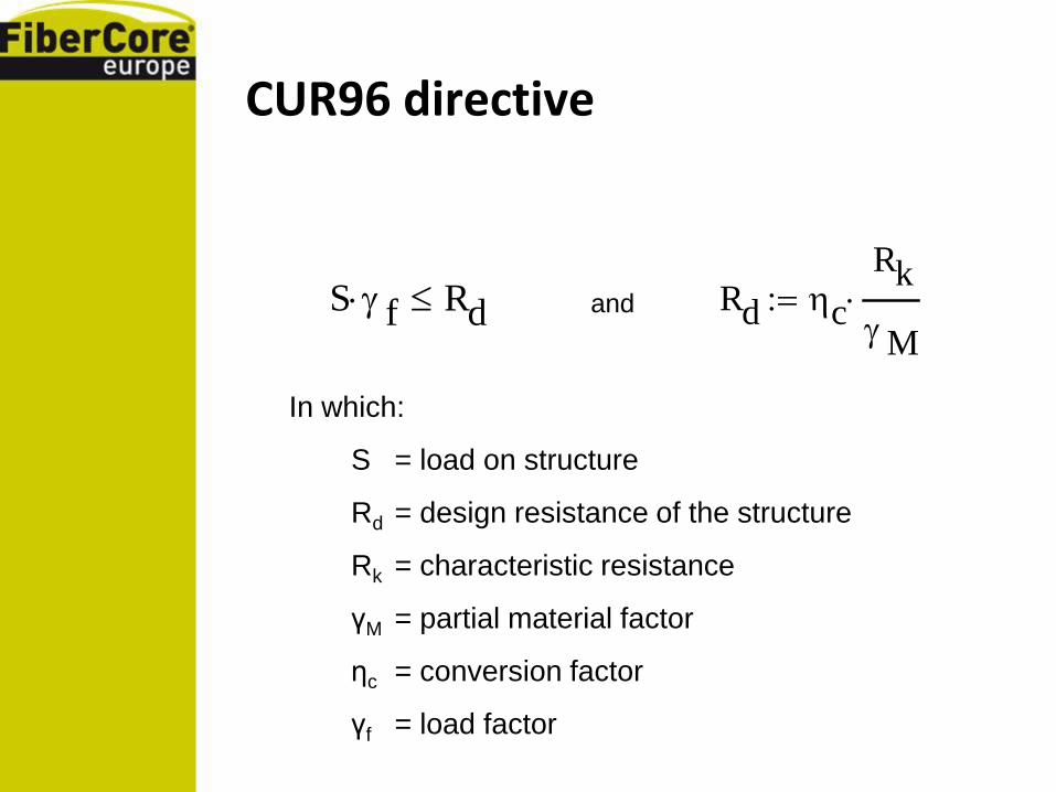
CUR96 directive
Rd c
Rk
M
with:
R.d the design resistance of the structure
R.k the characteristic resistance of the structure
?.M the partial material factor
?.c the conversion factor
?.f the load factor
S f Rd and
In which:
S = load on structure
Rd = design resistance of the structure
Rk = characteristic resistance
γM = partial material factor
ηc = conversion factor
γf = load factor

CUR96 directive
M Rd m
In which partial factors for uncertainty:
γRd = in resistance model and geometry
γm = caused by the nature of materials
and production methods used

CUR96 directive
c ct cv ck cf
In which conversion factors:
ηct = effects of temperature
ηcv = effect of moisture
ηck = creep
ηcf = fatigue
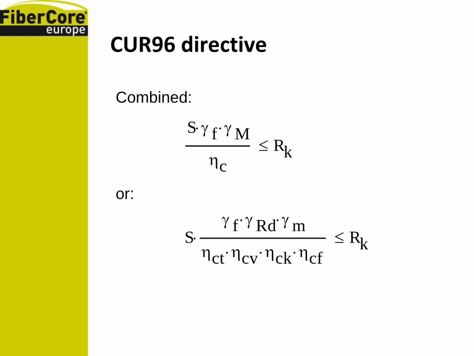
CUR96 directive
S f M
c
Rk
Combined:
S f Rd m
ct cv ck cf Rk
or:

Example…
With, e.g.:
γf = load factor = 1.0 (usability limit state)
γRd = model & geometry = 1.0
γm = materials & production = 1.2 (RTM, post cured)
ηct = effects of temperature = 1.0 (if T ≤ Tg - 40°C)
ηcv = effect of moisture = 1.0 (mostly dry)
ηck = creep = 0.8 (non crimp, 100 yrs)
ηcf = fatigue = 0.9
Follows:
S 1.64 Rk

“Think composites”

Composite material properties
First: design the required material
Step 1: the properties of the unidirectional layer
Variables:
• Fibre properties
• Resin properties
• Fibre volume fraction
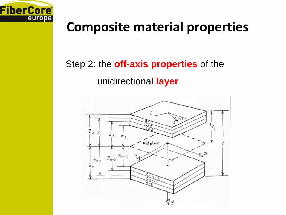
Composite material properties
Step 2: the off-axis properties of the
unidirectional layer
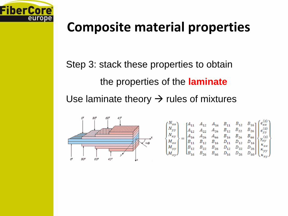
Composite material properties
Step 3: stack these properties to obtain
the properties of the laminate
Use laminate theory rules of mixtures
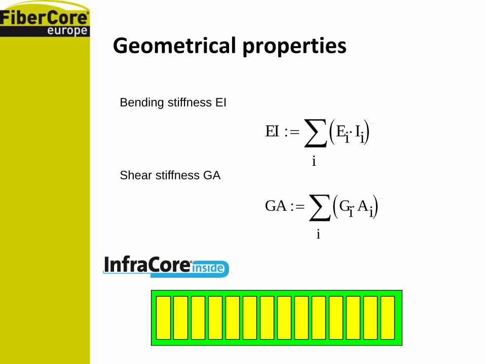
Geometrical properties
Bending stiffness EI
Shear stiffness GA
EI
i
Ei Ii
GA
i
Gi Ai

MathCad tool…

Important design considerations, especially for deck structures…
FiberCore Europe:
“Do not use composite materials in
infrastructure, unless…
these materials and structures are
robust and damage tolerant”

A
Fibre Reinforced Plastics
Inhomogenic, layered material
Fibres act as crack arrestors
Vulnerable to cracking between fibre layers (“interlaminar cracking” or “delamination”)
C
B
Crack tip
in composites

A lot can and does go wrong…

What is required for reliable use of FRP in Infra, are structures which…
• … after a serious impact load show no debonding and no cracking or delamination which may cause catastrophic failure, not directly and not after 10, 50 or even 100 years of intensive use;
• … have been proven with certified long term tests to be damage tolerant;
• … therefor have no potentially critical resin or adhesive dominated fracture paths;
• … preferably are monolithic, encompassing all structural parts, enabling robust joints to, and proper cooperation with, surrounding steel and concrete structuresl
• … have continuous reinforcing fibers which guarantee a robust connection between top skin – core – bottom skin.
• .

There is a robust solution…
The only technology to comply
with the requirements formulated in the
previous sheets, proven and patented
worldwide.

The essence of InfraCore Inside
… a brief introduction …
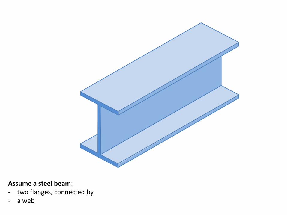
Assume a steel beam: - two flanges, connected by - a web
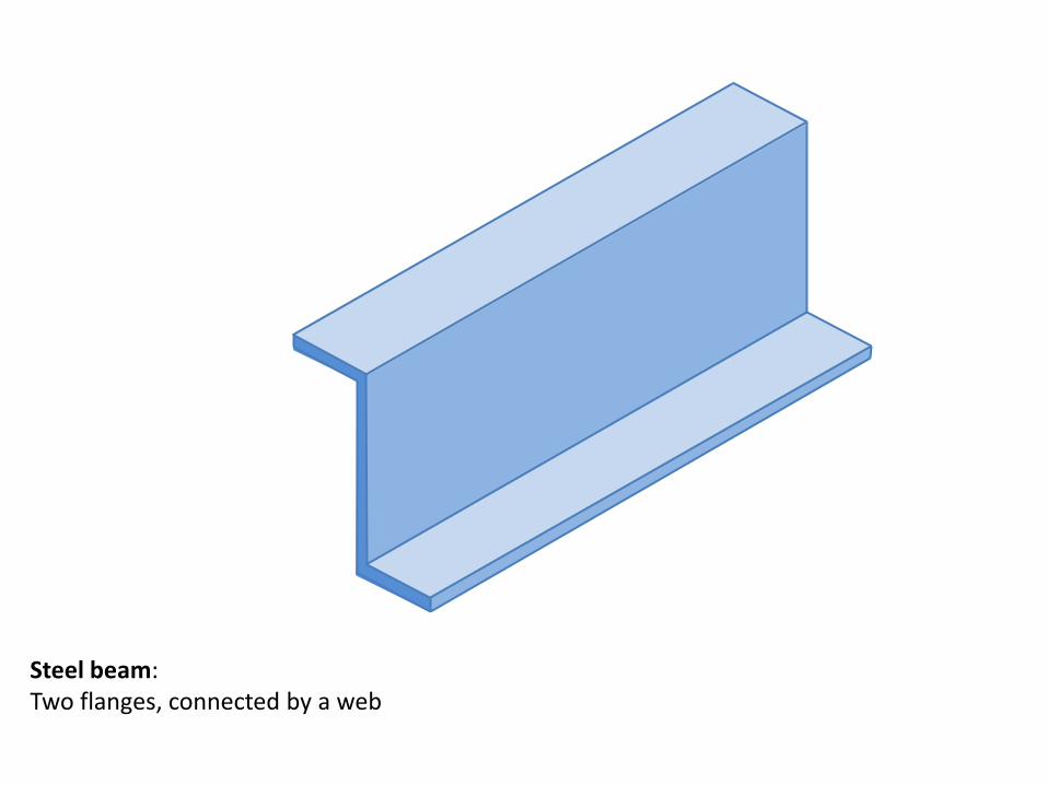
Steel beam: Two flanges, connected by a web

Steel beam: Two flanges, connected by a web

Steel beam: Two flanges, connected by a web

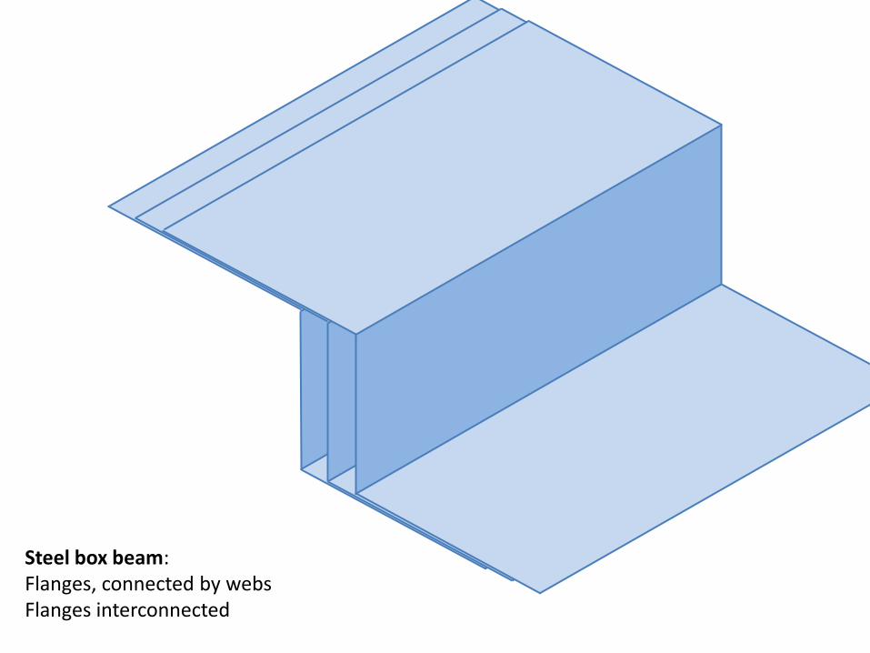
Steel box beam: Flanges, connected by webs Flanges interconnected
Steel box beam: Flanges, connected by webs Flanges interconnected

Steel box beam: Flanges, connected by webs Flanges interconnected

Steel box beam: Flanges, connected by webs Flanges interconnected
Steel box beam: Flanges, connected by webs Flanges interconnected

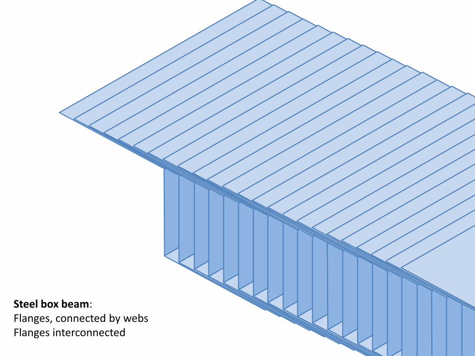
Steel box plate: Flanges, connected by webs Flanges interconnected

Steel beam: Two flanges, connected by a web

Glass Fibre Fabric beam: Two flanges, connected by a web One layer of ±45ᵒ fabric
x
y
z

Glass Fibre Fabric beam: Two flanges, connected by a web One layer of ±45ᵒ fabric + one layer of 0ᵒ fabric on flanges
x
y
z

x
y
z
Glass Fibre Fabric beam: Two flanges, connected by a web Flanges 0ᵒ/ ±45ᵒ fabric, web ±45ᵒ fabric

x
y
z
Carbon/Glass Fibre Fabric beam: Two flanges, connected by a web Flanges 0ᵒ carbon/ ±45ᵒ glass fabric, web ±45ᵒ glass fabric

x
y
z
Glass Fibre Fabric beam: Two flanges, connected by a web Flanges 0ᵒ/ ±45ᵒ fabric, web ±45ᵒ fabric + one layer op 90ᵒ fabric

x
y
z
Glass Fibre Fabric beam: Two flanges, connected by a web Flanges 0ᵒ/ ±45ᵒ fabric, web 90ᵒ/±45ᵒ fabric

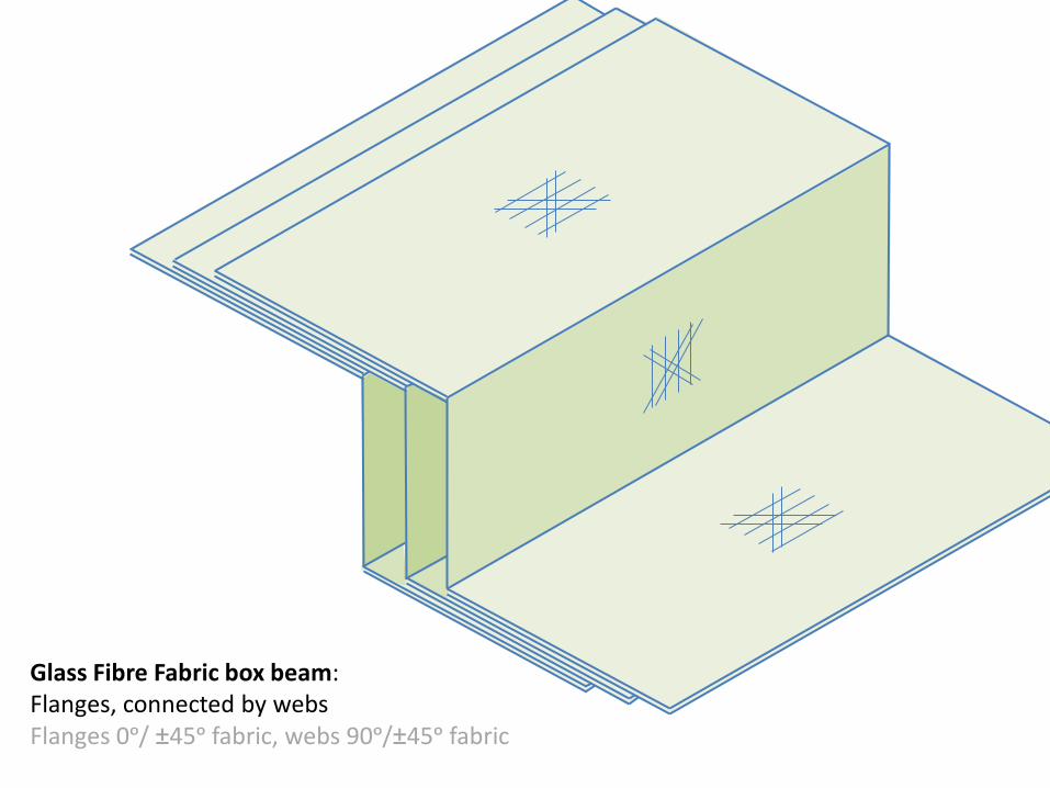
Glass Fibre Fabric box beam: Flanges, connected by webs Flanges 0ᵒ/ ±45ᵒ fabric, webs 90ᵒ/±45ᵒ fabric
Glass Fibre Fabric box beam: Flanges, connected by webs Flanges 0ᵒ/ ±45ᵒ fabric, webs 90ᵒ/±45ᵒ fabric

Glass Fibre Fabric box beam: Flanges, connected by webs Flanges 0ᵒ/ ±45ᵒ fabric, webs 90ᵒ/±45ᵒ fabric

Glass Fibre Fabric box plate: Flanges, connected by webs Flanges 0ᵒ/ ±45ᵒ fabric, web 90ᵒ/±45ᵒ fabric

Steel beam Loaded in three-point bending
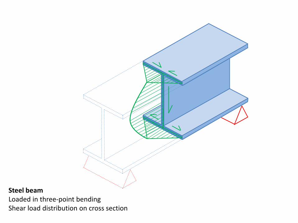
Steel beam Loaded in three-point bending Shear load distribution on cross section
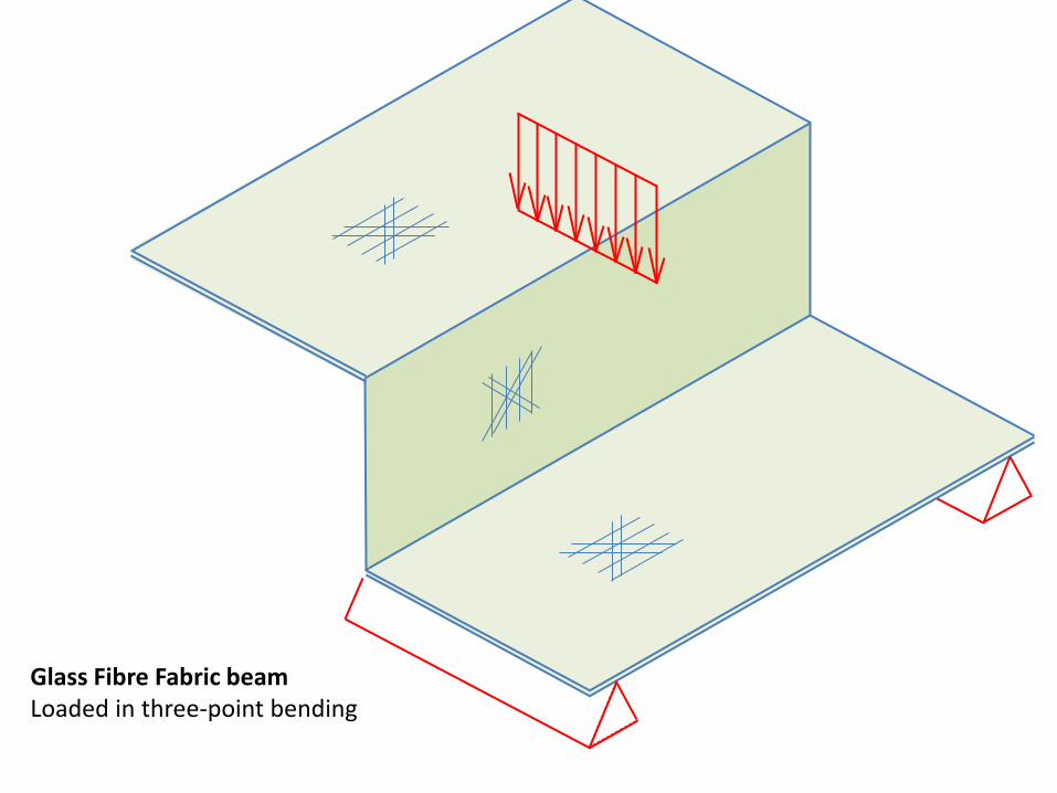
Glass Fibre Fabric beam Loaded in three-point bending
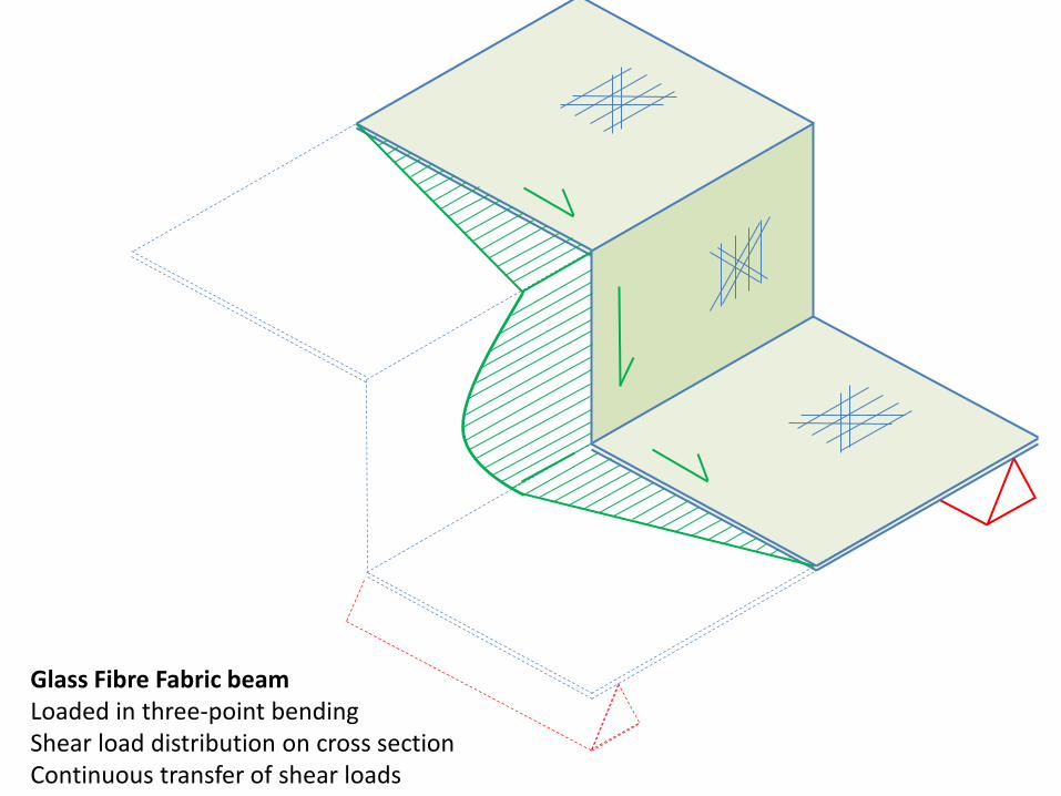
Glass Fibre Fabric beam Loaded in three-point bending Shear load distribution on cross section Continuous transfer of shear loads

A
Fibre Reinforced Plastics Inhomogenic, layered material Fibres act as crack arrestors Vulnerable to cracking between fibre layers (“interlaminar cracking”)
C
B

Glass Fibre Reinforced Plastic Multi-beam Box plate Beams are self-contained Little shear transfer between beams Impact damage may occur: local delamination
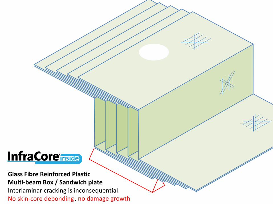
Glass Fibre Reinforced Plastic Multi-beam Box / Sandwich plate Interlaminar cracking is inconsequential No skin-core debonding , no damage growth
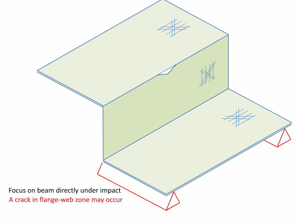
Focus on beam directly under impact
A crack in flange-web zone may occur

Focus on beam directly under impact Crack will not grow, constricted by fibres

Focus on beam directly under impact Beam can carry load despite crack Much residual surface to carry shear loads Stable situation
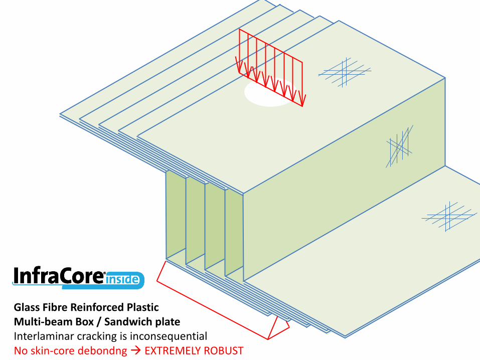
Glass Fibre Reinforced Plastic Multi-beam Box / Sandwich plate Interlaminar cracking is inconsequential No skin-core debondng EXTREMELY ROBUST
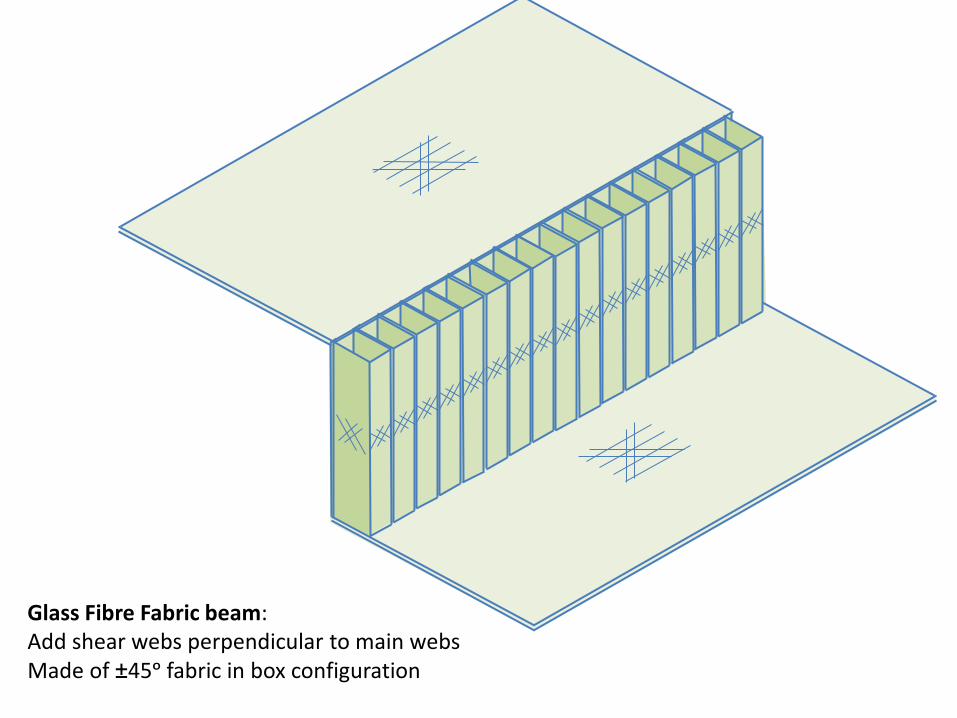
Glass Fibre Fabric beam: Add shear webs perpendicular to main webs Made of ±45ᵒ fabric in box configuration

Glass Fibre Fabric box beam: Flanges, connected by webs Flanges 0ᵒ/ ±45ᵒ fabric, webs 90ᵒ/±45ᵒ fabric, cross-webs ±45ᵒ fabric

Glass Fibre Fabric box beam: Flanges, connected by webs Flanges 0ᵒ/ ±45ᵒ fabric, webs 90ᵒ/±45ᵒ fabric, cross-webs ±45ᵒ fabric

GRP pultruded beam: Achilles heel Supported in three-point bending Impaced by hard object flange-web crack initiation

GRP pultruded beam: Achilles heel Loaded in three-point bending Unarrested crack growth catastrophic failure
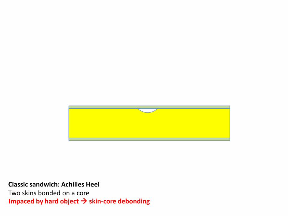
Classic sandwich: Achilles Heel Two skins bonded on a core Impaced by hard object skin-core debonding
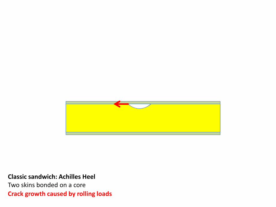
Classic sandwich: Achilles Heel Two skins bonded on a core
Crack growth caused by rolling loads
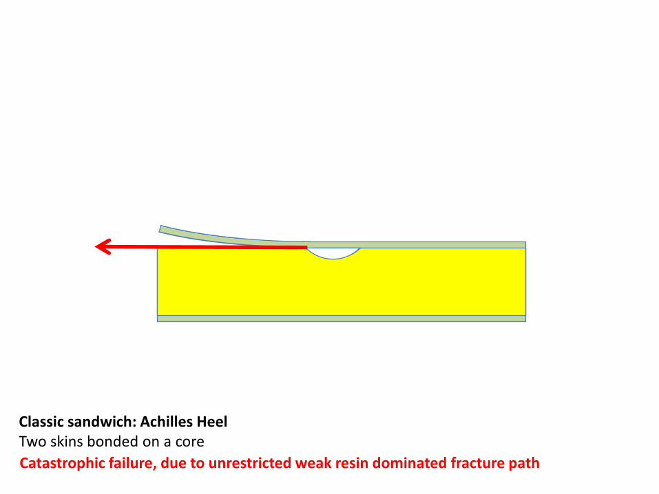
Classic sandwich: Achilles Heel Two skins bonded on a core
Catastrophic failure, due to unrestricted weak resin dominated fracture path

Multi beam plate: Achilles Heel Many box beams bonded together Impaced by hard object crack in and between webs

Multi beam plate: Achilles Heel Many box beams bonded together Crack growth caused by rolling loads
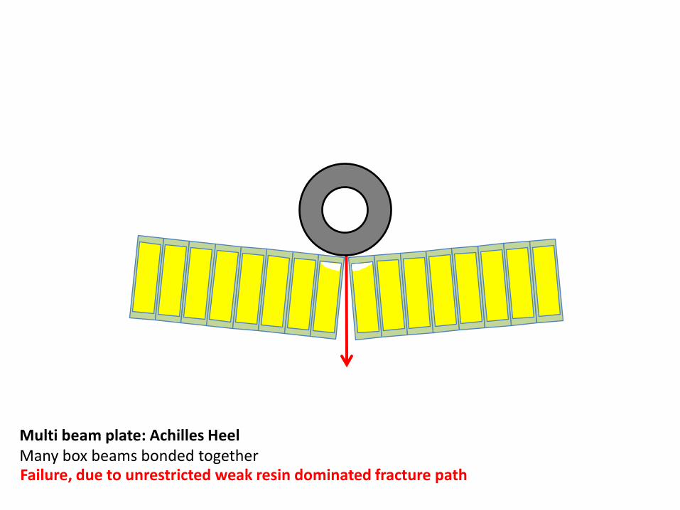
Multi beam plate: Achilles Heel Many box beams bonded together Failure, due to unrestricted weak resin dominated fracture path

Multi beam plate: Achilles Heel Many box beams bonded together, with additional deck layers Impaced by hard object two weak resin dominated fracture paths

Glass Fibre Fabric box beam: Extreme robustness

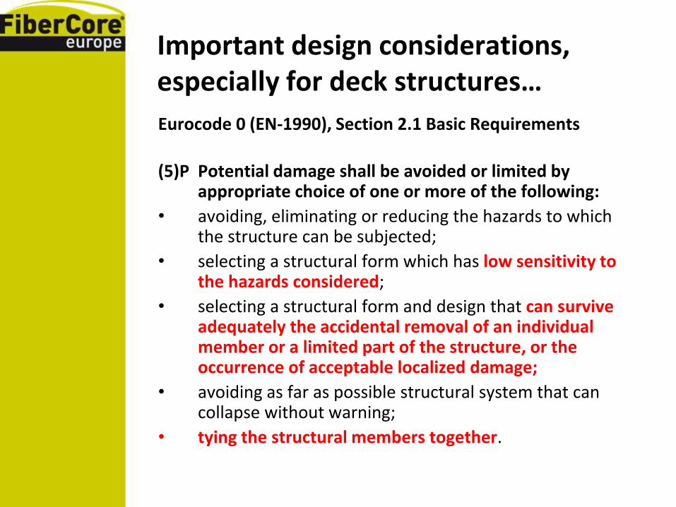
Important design considerations, especially for deck structures…
Eurocode 0 (EN-1990), Section 2.1 Basic Requirements
(4)P A structure shall be designed and executed in such a way that it will not be damaged by events such as:
• explosion
• impact, and
• the consequences of human errors,
to an extent disproportionate to the original cause.
Important design considerations, especially for deck structures…
Eurocode 0 (EN-1990), Section 2.1 Basic Requirements
(5)P Potential damage shall be avoided or limited by appropriate choice of one or more of the following:
• avoiding, eliminating or reducing the hazards to which the structure can be subjected;
• selecting a structural form which has low sensitivity to the hazards considered;
• selecting a structural form and design that can survive adequately the accidental removal of an individual member or a limited part of the structure, or the occurrence of acceptable localized damage;
• avoiding as far as possible structural system that can collapse without warning;
• tying the structural members together.

Important design considerations, especially for deck structures…
Eurocode 0 (EN-1990), Section 2.1 Basic Requirements
(6) The basic requirements should be met:
• by the choice of suitable materials,
• by appropriate design and detailing, and
• by specifying control procedures for design, production, execution, and use relevant to the particular project.

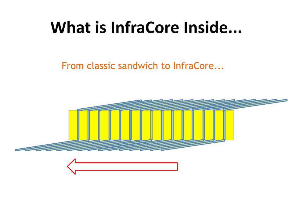
What is InfraCore Inside...
From classic sandwich to InfraCore...

What is InfraCore Inside...
From classic sandwich to InfraCore...

What is InfraCore Inside...
From classic sandwich to InfraCore...

What is InfraCore Inside...
From classic sandwich to InfraCore...
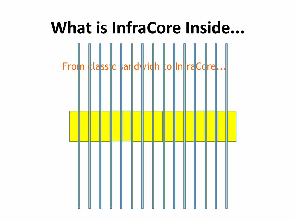
What is InfraCore Inside...
From classic sandwich to InfraCore...

What is InfraCore Inside...
From classic sandwich to InfraCore...
What is InfraCore Inside...
From classic sandwich to InfraCore...
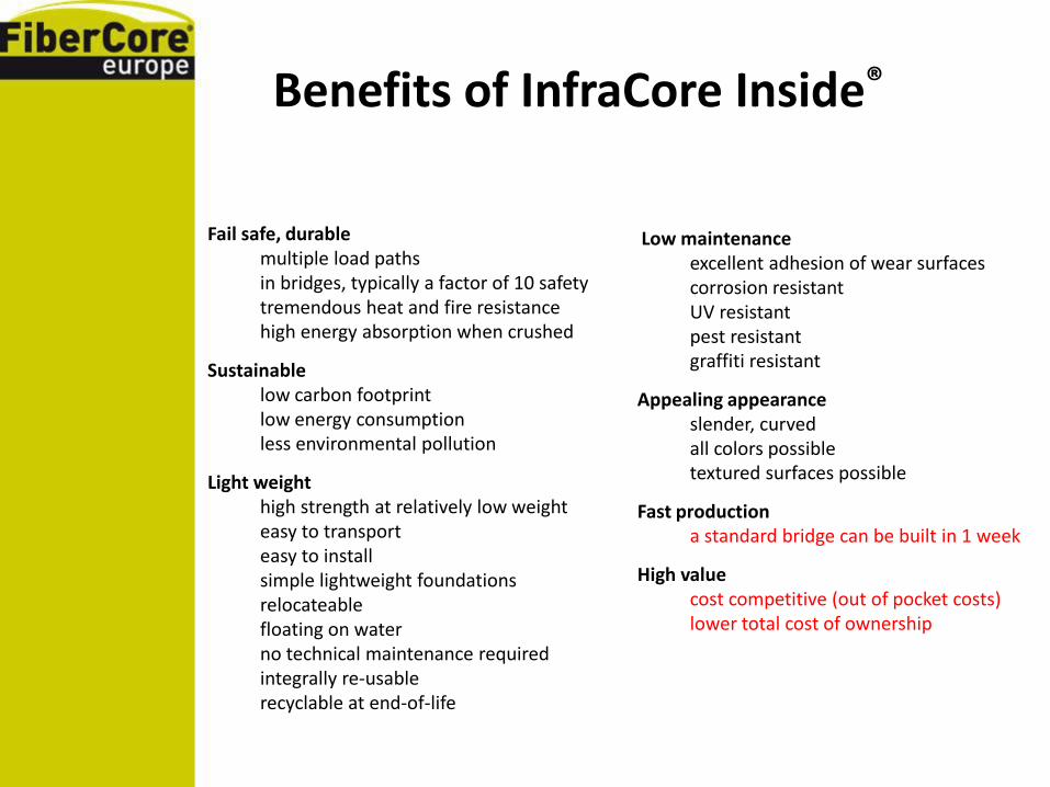
Benefits of InfraCore Inside®
Fail safe, durable
multiple load paths in bridges, typically a factor of 10 safety
tremendous heat and fire resistance
high energy absorption when crushed
Sustainable
low carbon footprint low energy consumption
less environmental pollution
Light weight high strength at relatively low weight easy to transport easy to install simple lightweight foundations relocateable
floating on water no technical maintenance required
integrally re-usable
recyclable at end-of-life
Low maintenance
excellent adhesion of wear surfaces corrosion resistant UV resistant pest resistant graffiti resistant
Appealing appearance
slender, curved
all colors possible
textured surfaces possible
Fast production
a standard bridge can be built in 1 week
High value
cost competitive (out of pocket costs) lower total cost of ownership
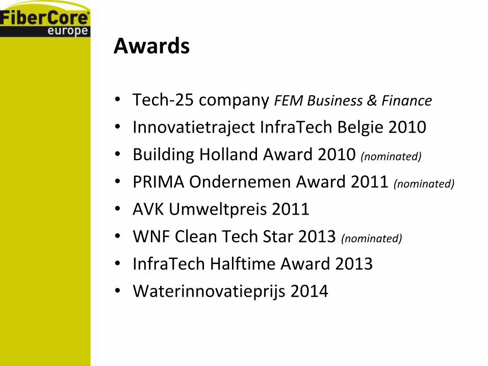
Awards
• Tech-25 company FEM Business & Finance
• Innovatietraject InfraTech Belgie 2010
• Building Holland Award 2010 (nominated)
• PRIMA Ondernemen Award 2011 (nominated)
• AVK Umweltpreis 2011
• WNF Clean Tech Star 2013 (nominated)
• InfraTech Halftime Award 2013
• Waterinnovatieprijs 2014


