84
Composites Inspection and Repair Steve Kane – Adjunct BCC Aerospace Technology In conjunction with SpaceTEC®

Composites Inspection and
RepairSteve Kane – Adjunct
BCC Aerospace TechnologyIn conjunction with SpaceTEC®

Topics
Introduction Composites Review– Characteristics– Materials– Fabrication Techniques– Composites Safety– Shop Safety
Inspection Damage IdentificationRepair Techniques

Outline
Introduction – Composites Inspection and Repair– Day 1 – PowerPoint Lecture:
• Composites Characteristics, Materials, Fabrication Techniques, Composites Safety, Shop Safety, Inspection, Damage Identification, Repair Techniques• Lunch• Lab Project 1 – Composite Sandwich Construction–
– Day 2 – Review, Project Assessment• Lab Project 2 – Damage Inducement, Core Repair, Scarf Repair Technique• Lunch• Exam, Discussion, Certificate
Introduction
Purpose:
– Inspection and Repair Workshop– Follow-on to Introduction to Composites
• Provide knowledge of and a practical application forinspection of composites and repair of damages
– Intended to be advisory in nature• Repair data provided by OEM manufacturers, qualified engineers, and/or regulatory agencies must be consulted in any inspection and/or repair method

Composites Review

Definition of Composites
From Introduction to Composites:– What are Composites?
• Two or more materials working together» Each contributes its own structural properties» Each retains its unique identity
• Two major components:» Reinforcing Fiber – ceramic – strong but brittle» Matrix (glue) – plastic – tough yet flexible
How They Work
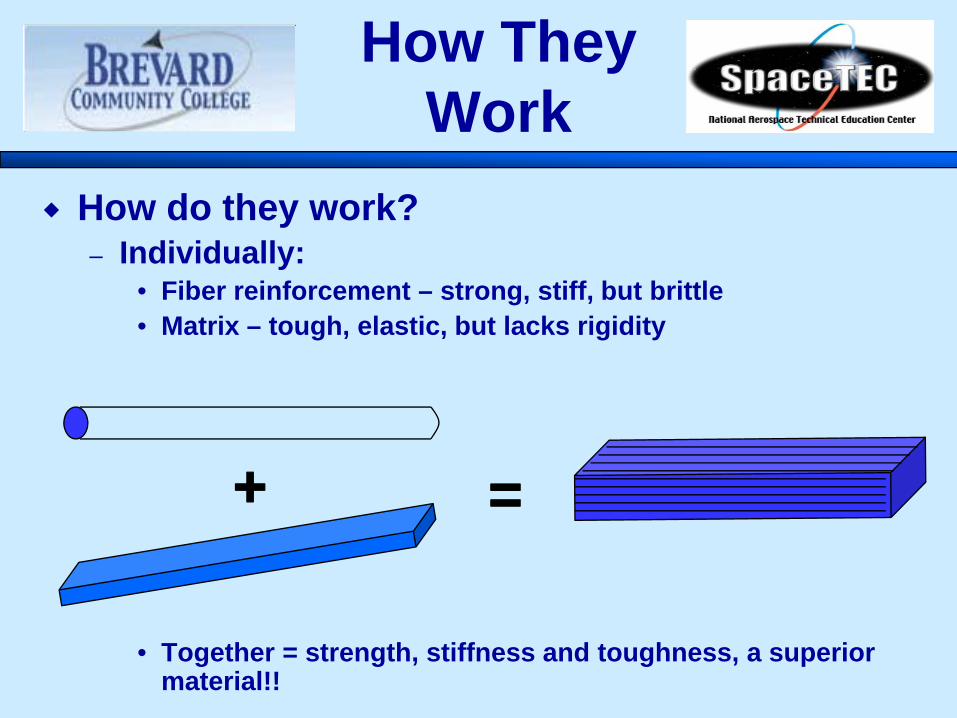
How do they work?– Individually:
• Fiber reinforcement – strong, stiff, but brittle • Matrix – tough, elastic, but lacks rigidity
• Together = strength, stiffness and toughness, a superior material!!
+ =

Types
Three Basic Types:– Natural – occurs in nature
• Wood– Artificial – produced from naturally occurring
materials to improve on natural• Adobe• Plywood• Concrete
– Synthetic – produced from artificial materials to improve on artificial
• Fiberglass• Graphite (Carbon) Fiber• Aramid (Kevlar)

• Specific Strength:
Characteristics, cont.

• Specific Stiffness:
Advantages, cont.

Advantages
Advantages of Composites:– Do not corrode– Smooth surfaces relatively easy to achieve– Many manufacturing methods available:
• Hand layup, Vacuum bagging, Resin Transfer Molding (RTM), Pultrusion, Filament winding, Resin infusion
– High strength/stiffness-to-weight ratios possible
• 4-10 times that of metals– Structures can be “tailored” to meet specific
applications• Orienting fibers to carry specific loads
Limitations
What are their limitations?– Fiber reinforcement prone to cracking
• Brittle nature means little or no elasticity» Sudden failure at yield point
• Matrix mitigates brittleness» Works as stop-drill would in aluminum» Not much chance all cracks will “line up”» Shear forces bog down
• Bicycle Analogy» Solid ground – moves freely» Softer ground – more resistance

Disadvantages
Disadvantages:– Labor intensive– Special training needed– Raw materials expensive– Manufacturing equipment expensive– Health and safety concerns for materials – Cannot be recycled– Little or no warning before failure– Some materials may not be compatible with
metals• Galvanic Series
» Carbon (noble) and aluminum (active)

Weave Patterns
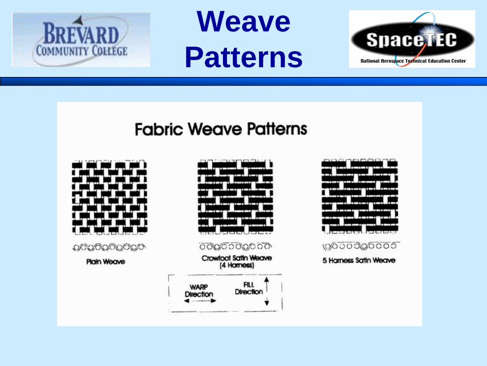
• Plain Weave– One over and one under every other yarn– Provides fabric stability– The least pliable, least strong weave
• Basket Weave– Similar to plain but two warp yarns over
and under– More pliable and stronger than plain
• Crowfoot (Four-Harness Satin)– More pliable, easier to form on compound
curves– Three yarns over and one yarn under
• Five-Harness Satin (5HS)– Similar to Crowfoot but one more filling
yarn, 4 over and 1 under– More pliable than crowfoot
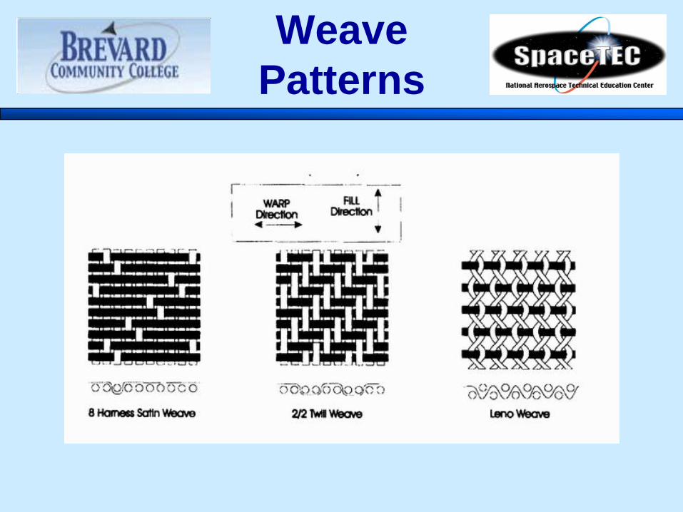
• Eight-Harness Satin (8HS)– Similar to 5-harness except one yarn floats
over seven and under one– Very pliable weave and has good drape– Great for compound curve surfaces– Most expensive weave
Weave Patterns
Weave Patterns
Weave Patterns
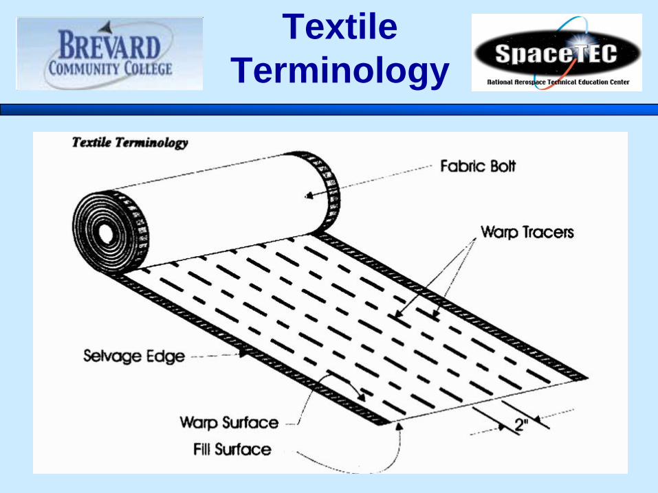
• Warp Direction– Parallel to the “Long” direction of the roll– Also defined as parallel to the “selvage” edge
• Fill Direction– 90 degrees to the Warp direction– Selvage edge to selvage edge– Sometimes called “Weft” direction
• Selvage Edge– Tightly woven edge to prevent edge raveling– Parallel to warp threads
• Bias– A 45 degree angle to the warp threads– Fabric can be stretched along the bias but seldom along warp
Textile Terminology
Textile Terminology

Textile Terminology

• Advanced Composites are by design– Orientation of fibers is proportional to properties
• The more fibers in a given direction, the stronger and stiffer
– Unidirectional (0) degrees for tension, compression, or bending
– Bidirectional (+/- 45’s) degrees for shear
– Control fiber angles +/- 2 degrees
– Sandwich Construction
– Enhances performance by placing the load carrying fibers on the outside of the part
Fiber Orientation

• Symmetry– A laminate in which all of the ply orientations
are symmetrical about the mid-plane of the laminate
Common Layup Terms

• Balance– A “Balanced”
laminate has equal numbers of + and – angled plies
Common Layup Terms
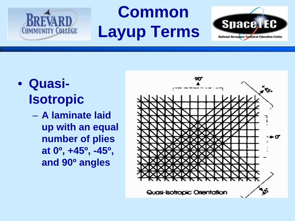
• Quasi-Isotropic– A laminate laid
up with an equal number of plies at 0º, +45º, -45º, and 90º angles
Common Layup Terms

• Nesting vs. Stacking– Placing plies so the fibers of one ply align with the
yarns of the adjacent ply– Only possible with harness-satin weaves
Common Layup Terms

Shop Safety
• Working Environment:– Good housekeeping directly impacts
safety– Keep area neat & orderly– Properly dispose of mixing containers– Keep fabric remnants swept up– Wipe up spills, keep tools clean– Do not block access to safety equipment
Environment

• Personal safety while sanding or drilling:– Respirators must be worn– Wear shop coat to minimize particles
entering pores of skin– Use eye protection– Always shower at the end of the day after
working with composites
Personal Safety

Shop Safety
• Compressed air in the shop area– Moisture is your enemy!
• Check moisture traps often– Air Tools
• Flexible lines can take on a life of their own if unsecured• Disconnect tools from air supply before changing
cutters, sanding discs and drills• Point the exhaust away from other people
– Never blow surfaces with compressed air!• Causes projectiles• Can cause delaminations
– Use a brush or vacuum for cleaning parts, machines, and work tables

• Tool Safety– Use Eye Protection
• Safety glasses with side shields are a must– Wear dust mask when cutting, drilling, sanding
• NIOSH-rated– Cutting
• When Cutting:– Keep hands, fingers away from cutting surfaces
• Razor Knives– Very sharp, use caution
Tool Safety
• Tool Safety, cont.– Drilling
• When Drilling:– Back up materials
» Don’t use your hands!» Always know what is behind
– Never force drills!» Will cause breakouts on other side» Can disbond laminate-to-core interface» Use high speed, low pressure» Let the bit do the work!
Tool Safety
• Tool Safety, cont.– Sanding
• When Sanding:– Wear eye protection/dust masks
• Work in a suitable area:– Down-draft tables– Exhaust systems
• Clean up debris:– Clean up before tracking around– Wash hands before eating or using the restroom!
Tool Safety

Sandwich Structures
• Sandwich structures:– Combination of strong, thin skins and a
relatively light “core” material– Very efficient structures with high stiffness-to-
weight ratios– Also called “honeycomb”
• Chief purpose of core:– Passes shear forces between the skin surfaces– Allows substantially improved structural
properties in thicker sections with only slight increase in weight

Sandwich Structures
• Typical sandwich structures:
Sandwich Structures
• Disadvantages of sandwich construction:– Sandwich structures have thin skins that can be
easily damaged by even minor impacts.– Susceptible to moisture intrusion:
• Can cause unintentional weight gain• Freezing may cause disbonds (if subjected to lower
temperatures of higher altitudes)• If core becomes contaminated with oil, fuel or
hydraulic fluid, it is virtually impossible to remove completely and must be replaced
• Honeycomb– Form most commonly used in aerospace
• Made from Nomex (aramid paper), fiberglass, or aluminum
• Fire retardant, flexible and lightweight• Offers best strength-to-weight ratio
• Cell shape– Most common is hexagon, known as Hex
Core• Suitable for flat panels• Difficult to curve
Sandwich Structures

Sandwich Structures
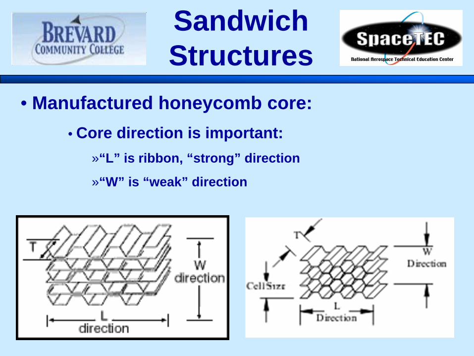
• Manufactured honeycomb core:• Core direction is important:
»“L” is ribbon, “strong” direction
»“W” is “weak” direction
Sandwich Structures
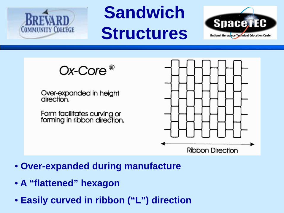
• Over-expanded during manufacture
• A “flattened” hexagon
• Easily curved in ribbon (“L”) direction
Sandwich Structures
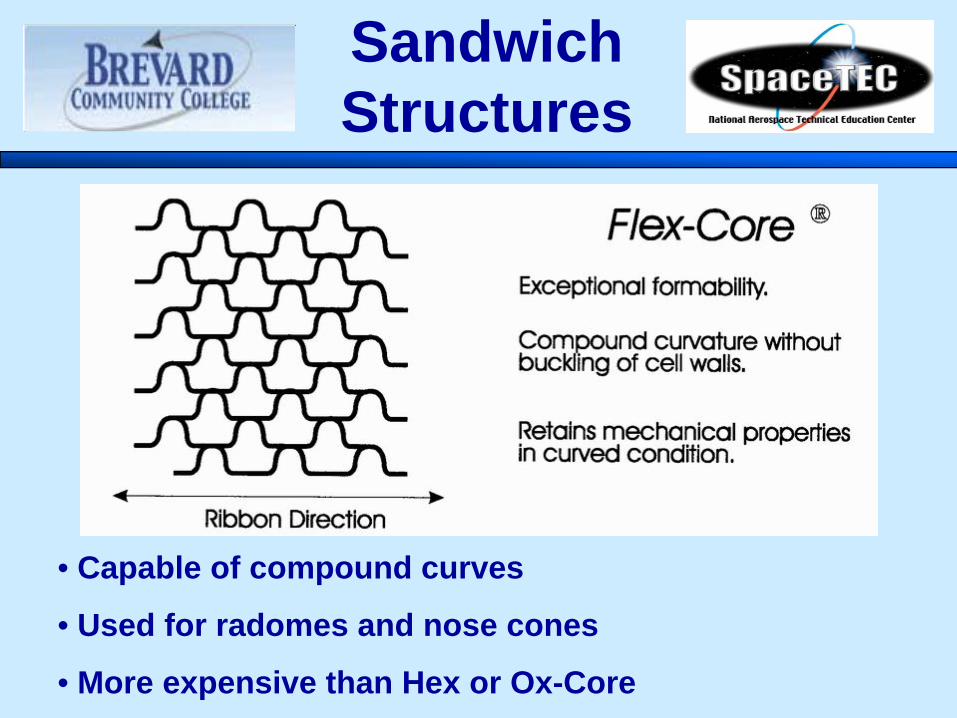
• Capable of compound curves
• Used for radomes and nose cones
• More expensive than Hex or Ox-Core
Sandwich Structures

• Foam Core– Offers higher density than honeycomb– Greater crush resistance– Bonds to skin are less strong– Must be cut and shaped to fit– Common types
• Polystyrene• Polyurethane• Polyvinyl chloride (PVC)
Sandwich Structures
• Polystyrene Foam– Used extensively in sail and surf board
manufacture – Light (40kg/m3 ), inexpensive, easy to sand
characteristics – Low mechanical properties
• Rarely employed in high performance component construction
– Cannot be used with polyester resin systems• Will be dissolved by the styrene present in the resin
Foam Core
• Polyurethane Foam– Moderate mechanical properties
• Foam surface at the resin/core interface tends to deteriorate with age
» Leads to skin delamination– Can readily be cut and machined to
required shapes or profiles – Structural applications limited to
formers to create frames or stringers for stiffening components
– Used in lightly loaded sandwich panels
• Thermal insulation
Foam Core
• Polyvinyl Chloride (PVC) Foam– Closed-cell construction– Good mechanical properties– One of the most commonly used core materials
for high performance sandwich structures– Good solvent resistance– Will work with most available matrix materials– Can be formed in compound shapes at elevated
temperatures in vacuum mold
Foam Core
• Syntactic Foam– Mixture of microspheres (miniature glass
spheres), epoxy resin– Mixture ratio controls strength and density
• Can use high-strength microspheres, toughened resins
• Can become heat-resistant with addition of high temperature resins
– Used primarily as a non-structural filler material
– Can be used in foam core repairs
Foam Core

• Balsa Wood– Excellent structural core material– Low cost, easy to use– Can have moisture problems– Can burn in a fire
• Used less in aviation due to FAA flammability requirements
– Used primarily in marine construction• Inherent floatability
Wood Core

• Cutting Foam:– Hot Wire Cutting
• Easiest method for foam cores• Care must be taken with smoke
– Band saw• Can be used with miter for angled
surfaces– Razor knife
• Hand finish, trim work
Shaping
• Sanding:– Lightweight material is easy to sand,
shape– Can use belt sanders, hand sanders– Foam core materials can be sanded
with another piece of like foam
Shaping

Machining Composites
• For drilling, cutting, sanding or grinding of composite materials– Do not use cutting fluids as fibers may absorb
them– Do not use same cutting tools on graphite and
Kevlar– Drilling and countersinking
• Delamination, fracture and breakout are types of failures

• Delamination– Peeling away of the bottom layer as the force
of drill pushes the layers apart• Fracture
– Occurs when a crack forms along one of the layers due to the force of the drill
• Breakout – Occurs when the bottom layer splinters as drill
completes the hole• Separation
– Occurs when gap opens between layers as The drill passes through successive layers
Machining Composites

• The material being drilled should be backed with wood whenever possible to prevent these problems!
• When exiting the back side of a hole with a drill, very light or no pressureshould be used. don’t push drill through, Let It Cut! This will prevent delaminations.
Machining Composites
• Carbide drill bits will work on all types of composites.
• They also last longer than standard steel drills.
• Drill motor speed is important– High speed works best– Do not use excessive force– Dagger or spade drills can be used.
They reduce the tendency of the fibers to break rather than be cut
Machining Composites

• Hole Saws– Use special “Diamond Dust” cutting edges
• Band Saws– Special “Diamond Dust” or carbide blades– 12 To 14 TPI
Machining Composites

• Fasteners– Composi-lok– Must be made of titanium or corrosion
resistant steel– Aluminum fasteners must not be used because
of tendency to corrode the aluminum
Machining Composites
Inspection and Damage Identification
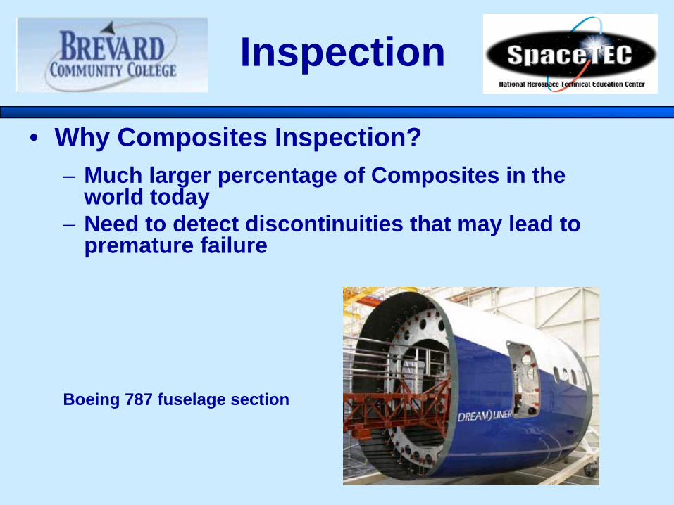
• Why Composites Inspection?– Much larger percentage of Composites in the
world today– Need to detect discontinuities that may lead to
premature failure
Inspection
Boeing 787 fuselage section
Composite Damage
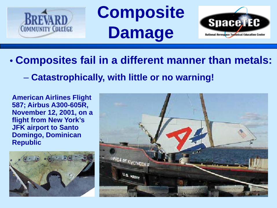
• Composites fail in a different manner than metals:– Catastrophically, with little or no warning!
American Airlines Flight 587; Airbus A300-605R, November 12, 2001, on a flight from New York’s JFK airport to Santo Domingo, Dominican Republic

Composite Damage
Airbus A-300-308 aircraft experienced control difficulties shortly after takeoff. After returning to the origin airport, it was discovered that the majority of the Airbus' rudder had torn away from the vertical stabilizer.
Composite Damage
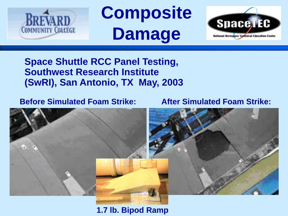
Space Shuttle RCC Panel Testing, Southwest Research Institute (SwRI), San Antonio, TX May, 2003
Before Simulated Foam Strike: After Simulated Foam Strike:
1.7 lb. Bipod Ramp

Composite Inspection
• Two Classifications of Inspection– Nondestructive Inspection
• Visual• Ultrasonic• Infrared• Shearography• Thermography
– Destructive Testing• Coupon testing
Visual
• Simplest nondestructive technique for inspecting laminates– Identifies surface imperfections:
• Impact damage (scuffing, chipping, surface cracking, or crazing)
• Near-surface delaminations (appear as bulges)• Severe disbonding (damage appears white)• With access to back side, illumination will make internal
defects such as delaminations visible as dark or grey areas
• Main tool for visual inspections:• Good light source
» Low incident-angle illumination
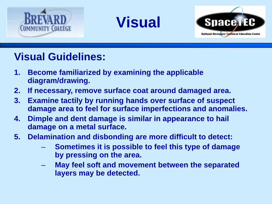
Visual Guidelines:1. Become familiarized by examining the applicable
diagram/drawing.2. If necessary, remove surface coat around damaged area.3. Examine tactily by running hands over surface of suspect
damage area to feel for surface imperfections and anomalies. 4. Dimple and dent damage is similar in appearance to hail
damage on a metal surface.5. Delamination and disbonding are more difficult to detect:
– Sometimes it is possible to feel this type of damage by pressing on the area.
– May feel soft and movement between the separated layers may be detected.
Visual
Visual
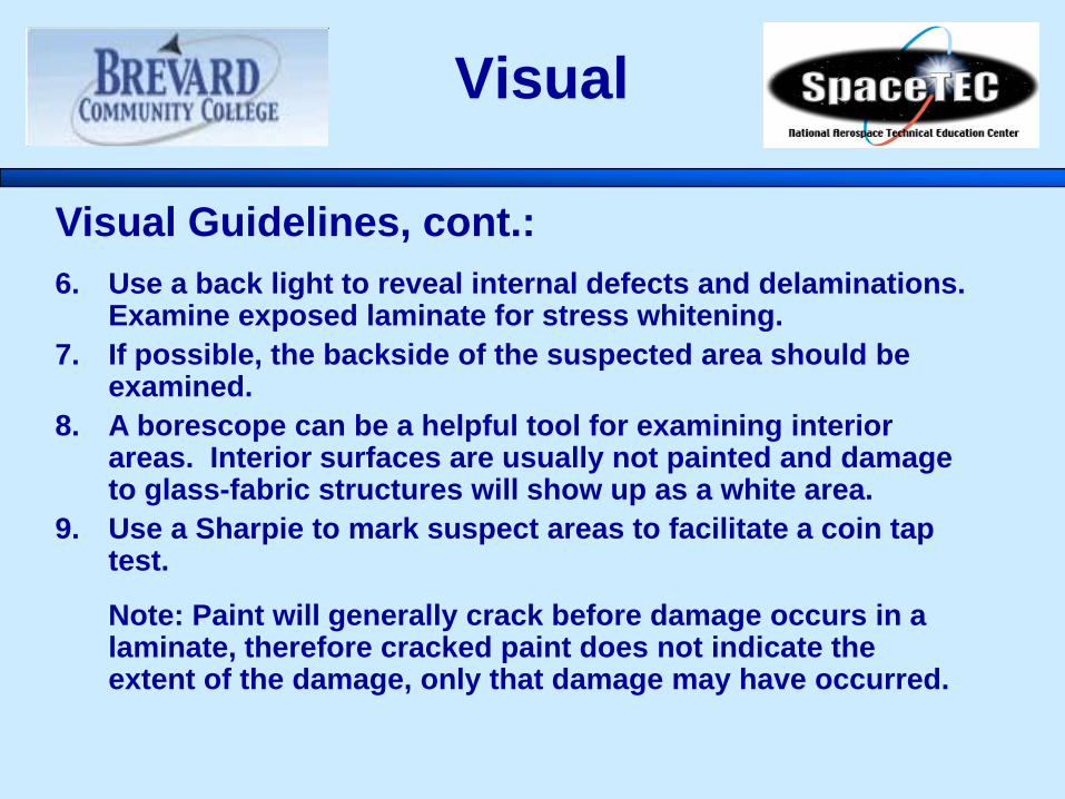
Visual Guidelines, cont.:6. Use a back light to reveal internal defects and delaminations.
Examine exposed laminate for stress whitening.7. If possible, the backside of the suspected area should be
examined.8. A borescope can be a helpful tool for examining interior
areas. Interior surfaces are usually not painted and damage to glass-fabric structures will show up as a white area.
9. Use a Sharpie to mark suspect areas to facilitate a coin tap test.
Note: Paint will generally crack before damage occurs in a laminate, therefore cracked paint does not indicate the extent of the damage, only that damage may have occurred.

Acoustic
• Manual Coin Tap Test– Primitive
» Most common method for hidden damage» Hearing-based, manual test practiced widely in
the aircraft industry » Used to determine laminate damage in a
composite » Acoustic sounds are produced when a small
metal object is tapped on a surface» Looking for clear, sharp sound» Dull thud indicates a void or delamination

CATT
• Computer-Aided Tap Test (CATT)– Automated: – Quantitative and imaging capabilities added
» Removes "human factor" responsible for variation
• Magnetic cam-action cart provides equally-spaced uniform taps • Simple encoding method gives imaging capability. • Effective for both composite and metal honeycomb structures. • Quantitative inspection results in the form of images that can be archived electronically.
David K. Hsu, [email protected].
http://faculty.washington.edu/scottcs/NSF/CNDE_14.pdf

• Three main methods of ultrasonic testing:– Pulse Echo:
• High frequency sound waves are introduced into a material and are reflected back from surfaces or flaws.
– Through Transmission• High frequency sound waves are introduced into a
material by a transmitter on one side and detected by a receiver on the other.
– Pitch/Catch • High frequency ultrasonic energy is transmitted at any
angle to the surface of a material and received as reflected energy returning at the reflected angle.
Ultrasonic

• Reflected sound energy is displayed versus time, and the inspector can visualize a cross section of the specimen showing the depth of features that reflect sound. f
Specimenflaw
0 2 4 6 8 10
initial pulse
crackecho
back surfaceecho
Oscilloscope, or flaw detector screen
Pulse-Echo

f
Pulse-Echo
• Advantages:– Can be performed with access to one side only– Can detect disbonds and delaminations deeper inside
structure than tap testing– Can give information about defect depth, down to which ply
in many cases
• Limitations:– Requires rather expensive portable equipment and a well-
trained operator– Difficult to cover large areas in a reasonable time
• More suitable for small areas– Does not work well with core materials
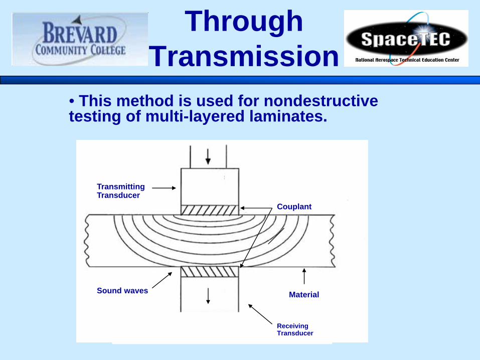
• This method is used for nondestructive testing of multi-layered laminates.
f
Through Transmission
Couplant
MaterialSound waves
Transmitting Transducer
Receiving Transducer
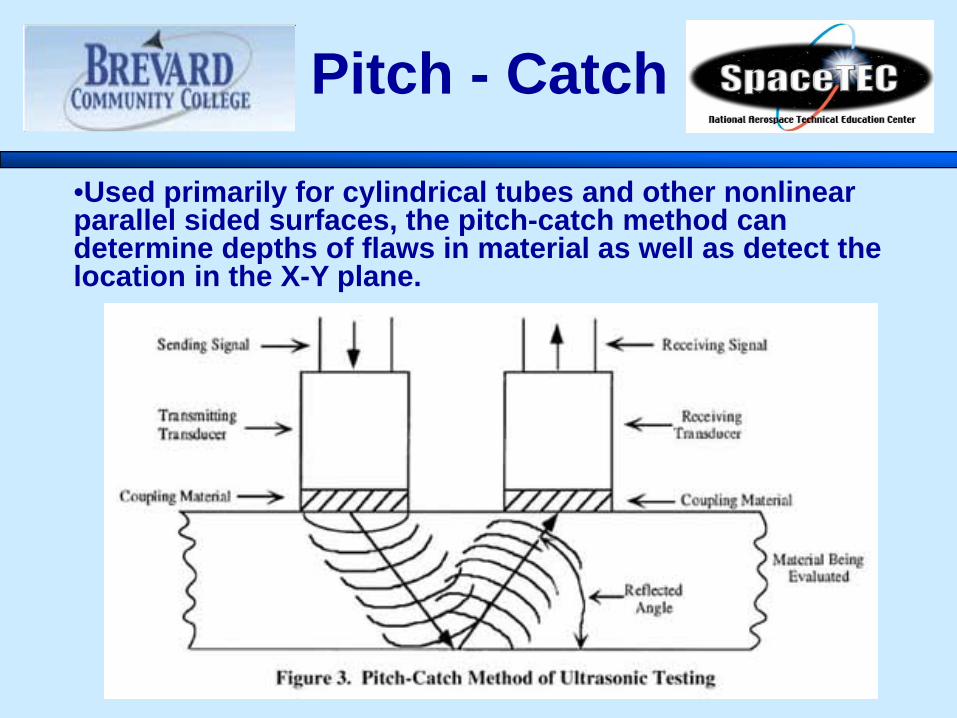
•Used primarily for cylindrical tubes and other nonlinear parallel sided surfaces, the pitch-catch method can determine depths of flaws in material as well as detect the location in the X-Y plane. f
Pitch - Catch
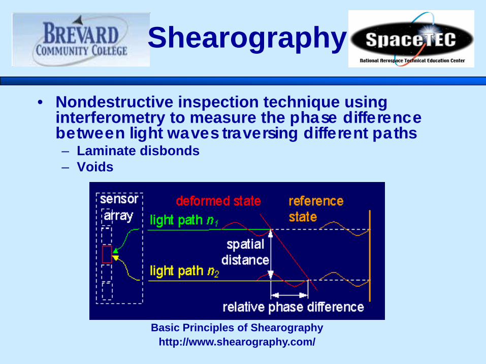
• Nondestructive inspection technique using interferometry to measure the phase difference between light waves traversing different paths– Laminate disbonds– Voids
Shearography
Basic Principles of Shearographyhttp://www.shearography.com/

• Nondestructive inspection technique using infrared light and an infrared camera to detect discontinuities– Video image is taken as parts are heated and cooled
• Uses thermal differences to gather information about the part – Core to laminate bonds– Ply delamination
Thermography
3-Dimensional Temperature Profile of an Impact Damage Zone on a Composite Pressure Vessel as Viewed by Infrared (IR) Thermography.
Nondestructive Evaluation (NDE) of Composite Structures
NASA-White Sands Test Facilityhttp://www.wstf.nasa.gov/Enable/Composites/NDE.htm
• High frequency, short wavelength radiant energy– Excellent for metallic inclusions– Effective for finding water trapped in honeycomb– Not good for delaminations parallel to the plane of
the X-ray image– Expensive equipment and training– Safety requirements
Radiography

Damage Classification

Types of Damage
• Damage classifications:– Cosmetic damage - a defect on the outer surface that does not involve the structural reinforcement (fibers). Usually only chips or scratches
– Impact damage - occurs if struck by a foreign object or from careless handling during transportation or storage.
– Penetrating - includes fractures and penetration through the laminate.
– Non-penetrating - includes abrasions, delaminations, surface impact, or gouges through one laminate surface.

• Damage classifications, cont.:– Solid laminate damage - structural or non-structural
damage which extends beneath the surface protection and affects the solid laminate structure underneath. Three types:
• Delamination - separation of layers of material in a laminate.
• Cracks - can occur in advanced composite structures, just as in metallic ones.
• Hole Damage - may occur from improper drilling techniques, over torqueing fasteners, or as a result of pull-through.
Types of Damage, cont.
Types of Damage, cont.
• Damage classifications, cont.:• Secondary bond damage - occurs between two pre-
cured components. Could be structural or non-structural in nature.
• Sandwich structure damage - damage to composite sandwich structures. Three types:
• Laminate only - damage to one side of the sandwich structure only with no core damage. Can be identified using the solid laminate damage classifications.
• Laminate and core - damage to one side of the sandwich construction and damage to the core. No damage to the opposite laminate surface.
• Sandwich penetration - damage to both sides of the sandwich construction. Both laminate surfaces are punctured and the foam core is exposed.

Repair Techniques
Preparation
• Once extent of damage is known:
• Prepare Environment:– Make sure the repair area has adequate ventilation.
– The area must be completely enclosed.– Control temperature and humidity.
• Min temp: 60 F (16 C); relative humidity > than 46%• Max temp: 75 F (24 C); relative humidity < than 71%
– Isolate area from machining or other processes that generate dust, oil vapors, or other contaminants.– Isolate adjacent surfaces that may come in contact with adhesives prior to application.

Repairs
• To ensure a sound repair:• Know the ply lay-up information such as ply
count and warp clocks– If you don’t know the ply count, measure the thickness
(one ply is generally between 0.008 and 0.010 inch) and divide by 0.009
• Remove surface contaminants with solvent
• Remove surface coatings (paint/gel coat) mechanically.
NEVER USE PAINT STRIPPERS!

Repairs, cont.
– Removal of core damage• If damage has occurred to core material, it must
be removed first, using a hole saw– Step-cutting (Scarfing)
• To accomplish the proper step-cuts in the laminate, each successive layer of fiber must be removed. Great care must be exercised to avoid further damage
– Cleaning• All Repairs Must Be Cleaned After Sanding.
Use Vacuum And Solvent.
DO NOT USE COMPRESSED AIR!

Sanding technique using vacuum sourcehttp://www.cirrusdesign.com/downloads/pdf/mc/mc20060801.pdf
Repairs, cont.

Summary
We’ve talked about:•What Composites Are
•Characteristics, Advantages and Disadvantages
•Materials
•Composites and Shop Safety
•Composite Damage, Inspection, and Repair
Any Questions?

Acknowledgements:• Maria Clinton and Gary Eisenberg, Antelope Valley Community College, Lancaster, CA• David K. Hsu, [email protected].• Joe Escobar, Composites: Tips for working on Cirrus composite structures. www.amtonline.com/publication/article.jsp • Ultrasonic Testing of Aerospace Materials http://www.nasa.gov/offices/oce/llis/0765.html• Lee T. Ostrom, Ph.D., CSP, CPE, Cheryl A. Wilhelmsen, MS; Detectability of Dents in Composite Materials, http://www.airlines.org/NR/rdonlyres/A6DADE79-6D14-40F8-8403-BB1AA43B699A/0/Wed1130a_LeeOstrom.pdf


