Microwave absorption properties of holey graphene/silicone rubbercomposites
Chun-Yu Chen a, b, Nen-Wen Pu a, *, Yih-Ming Liu c, Li-Hang Chen c, Chia-Hung Wu d,Tsai-Yi Cheng a, Ming-Hsien Lin c, Ming-Der Ger c, **, Yann-Jang Gong b, You-Yu Peng b,Peter M. Grubb e, Ray T. Chen e
a Department of Photonics Engineering, Yuan Ze University, Zhongli, Taoyuan 320, Taiwanb Chemical System Research Division, National Chung Shan Institute of Science and Technology, Longtan, Taoyuan 325, Taiwanc Department of Chemical & Materials Engineering, Chung Cheng Institute of Technology, National Defense University, Dasi, Taoyuan 335, Taiwand School of Defense Science, Chung Cheng Institute of Technology, National Defense University, Dasi, Taoyuan 335, Taiwane Department of Electrical and Computer Engineering, University of Texas, Austin, TX 78701, USA
a r t i c l e i n f o
Article history:Received 16 June 2017Received in revised form16 September 2017Accepted 1 October 2017Available online 7 October 2017
The complex permittivity and return loss (RL) for the composites of silicone rubber filled with holeygraphene nanosheets (HGNS, prepared by ultra-rapid heating during the step of thermal reduction/exfoliation of graphite oxide) were measured in the 3e18 GHz range. HGNS-based composites werefound to have significantly higher microwave absorption than composites incorporating other types ofgraphene reduced at lower heating rates. Even with only 1 wt.% loading, its experimentally measured RLreached �32.1 dB at 13.2 GHz with a thickness of 2 mm, and simulation suggested that at a thickness of3 mm its RL can be as low as �45.3 dB at 7.8 GHz. Material characterization indicated that the density ofthe holes increased with the temperature ramp rate, and the hole sizes ranged from 5 to 300 nm.Compared to other graphene samples, HGNS possessed significantly larger specific surface area andhigher density of defects, suggesting that defect-induced losses, interfacial polarization, and multiplereflection/scattering at the interfaces are the major loss mechanisms. Our simple and low-cost process aswell as the very low loading ratio of HGNS are advantageous for cost reduction in future applications.
Due to their wide applications in consumer electronics,communication devices, and stealth technology, extensive studieshave been carried out on the development of microwave absorbersand shields [1e13]. There have also been wide studies on polymer-based composites containing microwave-absorbing carbon in-gredients, such as carbon black, graphite, expanded graphite, car-bon fiber, CNTs, and graphene (or reduced graphene oxide, RGO)[14e34]. These efforts have been motivated by their advantagesof high absorption ability, wide band, light weight, thinness, flexi-bility, low cost, and stable thermal and chemical properties. Inparticular, carbon nanotubes (CNTs) [18e20,24] and graphene
.-W. Pu), mingderger@gmail.
[12,13,21e25,30e34] have the greatest potential as high-performance absorbing materials owing to their many desirableproperties, including unique geometry effects, high specific surfacearea, and high conductivity. In 2008, Liang et al. [31] first reported amicrowave shielding effectiveness of 21 dB at 8.2 GHz in epoxycomposites filled with 15 wt.% of graphene. In 2011, Bai et al. [21]and Wang et al. [22] separately discovered that graphene couldalso provide remarkable microwave absorption. Subsequently,Bhattacharya et al. [24] found that graphene can offer higher mi-crowave absorption than CNT, and Wen et al. [32] reported thatRGO outperforms graphite nanoplatelets in microwave shielding.To explain why graphene is superior to other nano-carbon micro-wave absorbers, some researchers proposed that graphene has aunique loss mechanism: multiple reflections from the dihedralangle formed between neighboring graphene sheets [21,23] andmultiple scattering from the corrugated graphene surfaces [32].Recently we have reported that well-dispersed, highly exfoliatedgraphene is capable of providing excellent microwave absorption
C.-Y. Chen et al. / Composites Part B 135 (2018) 119e128120
(�37.8 dB at 12.3 GHz) at very low loading of 1 wt.% [30]. Additionalstudies on the temperature-dependent microwave shielding [33]and absorption [34] performances of graphene have confirmed itsusefulness at elevated temperatures. Combinations of graphenewith other dielectric or magnetic nano-fillers, such as CNTs [25],Fe3O4 [35], hematite [36], a-Fe [37], CuS [38], Ni [39], and NiFe2O4[40], have also been demonstrated. These hybrid fillers haveexhibited improved microwave absorption compared to pure gra-phene. Here we present a study on the extraordinary microwaveabsorption performances of holey grapheneda new type of gra-phene full of holes, which can considerably affect its electromag-netic properties.
Due to its two-dimensional (2-D) geometry, graphene easilyrestacks during the fabrication process in many applications andthus loses its exceptional physical properties to a great extent. Forexample, restacking of graphene leads to lower capacity and ratecapability in applications of Li ion batteries (LIBs) [41e43] andsupercapacitors (SCs) [44]. Therefore, creating anti-restacking 3-dimensional (3-D) structures [45e54] is important for realizingthe full advantage of graphene. Researchers have reported excellentmicrowave absorption properties of many well-designed 3-Dporous materials, which have complicated structures and anti-restacking capability. For example, hierarchical porous ZnOflowers [55], hollow porous Ni/SnO2 hybrids [56], hierarchicalhollow CuS microspheres [57], ordered honeycomb SnO2 foams[58], flower-like CuS hollow microspheres composed of nanoflakes[59], yolk�shell structured composites [60,61], 3-D free-standinggraphene foam [62], and graphene/polymer foam [63] have beensuccessfully synthesized and their superior microwave absorption/shielding properties have been demonstrated.
Alternatively, we have found that creating a holey structure ongraphene nanosheets with outward-opening hole edges and asignificantly roughened surface morphology resulted in goodresistance to restacking [44]. Using such kind of holey graphene,improvements in the performances of LIBs [64e67] and SCs[44,68,69] have been achieved because the holes offer shortcuts forthe ions to diffuse rapidly into the interlayer space. Severalmethods have been proposed to produce holey graphene bydifferent research groups [64e71], and studies on its applications toLIBs and SCs have been reported recently. Another unique feature ofholey graphene is the high density of defects around the hole edges,which can serve as active sites for capturing extra Li ions and thusimprove the electrochemical properties of LIBs [72,73]. These de-fects can equally play an important role in microwave absorptionaccording to many previous studies [22,33,35,36,74e76]. Theattractive properties of holey graphenedthe anti-restacking abilityand high defect densitydsuggest that it should be very suitable forthe application in microwave absorption as well. We demonstratehere the excellent microwave absorbing performance of holeygraphene produced by an ultra-rapid heating method.
2. Experimental details
2.1. Materials
The starting material for the production of graphene nanosheets(GNS) and holey graphene nanosheets (HGNS) was natural graphitepowder (200 mesh, or particle sizes � 74 mm, acquired from AlfaAesar), which has 99.9995% purity and 2.25 g/cm3 density.
The silicone rubber (Momentive, RTV-615A and B) was a two-component (base A and curative B) liquid product, which curesby mixing the base and the curative in a 10:1 wt ratio. The curingtakes 24 h at 25 �C to permit handling, but the time can be short-ened considerably by heating.
2.2. Preparation of GNSs with various heating rates
Natural graphite was oxidized by the Staudenmaier method toform graphite oxide (GO). The GO powder was then thermallyreduced/exfoliated into various kinds of GNSs (or RGO) by heatingto 300 �C in an air-filled quartz tube at different temperature ramprates. The GNS samples prepared at temperature ramp rates of 1, 10,and 30 �C/min were named GNS300-1, GNS300-10, and GNS300-30, respectively.
2.3. Preparation of HGNS
The HGNS sample was obtained using an ultra-rapid heatingmethod [44]. To achieve an extremely high temperature ramp rate,GO powder was dumped onto the central zone of the quartz tubesurface preheated to 300 �C using a long metal tool, and instanta-neously reduced/exfoliated into HGNS. An ultra-high temperatureramp rate of about 100 �C/s (6000 �C/min) was achieved by thismeans, and the GO was rapidly reduced while CO2 gas was gener-ated between neighboring layers much faster than it could escape.The huge pressure not only exfoliated the layers but also creatednumerous holes at weak spots in the graphene sheets.
2.4. Material analysis
Observation of the morphology of the GNS and HGNS sampleswas carried out using a scanning electron microscope (SEM, Hita-chi, S-3000N) and a transmission electron microscope (TEM, FEI,Tecnai G2 F30). X-ray diffractometry (XRD, Rigaku D/Max 2200)was utilized to examine the crystal structure of graphene.Furthermore, a Renishaw inVia Raman Microscope was used tocharacterize the D and G bands of GNS and HGNS samples. Nitrogenadsorption isotherms were measured at 77 K with a MicromeriticsASAP 2010 Surface Area and Porosity Analyzer to determine theBrunauer-Emmett-Teller (BET) specific surface area (SSA) for GNSand HGNS samples. We also employed elemental analysis (EA,Thermo Scientific, Flash EA2000 CHNS/O Analyzer) for analyzingthe O and C atomic contents of the GNSs and HGNS.
2.5. Preparation of the microwave absorbing composite sheets
Uniform dispersion of graphene in the matrix is of utmostimportance for maximizing the performance of the composite. Pre-mixing using a planetary mixer in combination with repetitivecalendering (three roll milling) was employed to ensure a highdegree of graphene dispersion. A planetary centrifugal mixer(Thinky, AR-250) was employed in premixing graphene (GNS300-1,GNS300-10, GNS300-30, or HGNS) powder with silicone rubberbase (RTV-615A) for 10 min before degassing for 5 min. Once pre-mixing was complete, the viscous solution was further mixed bya three roll mill (Exakt, 80E). This was repeated 9 times so thatuniform dispersion of GNS or HGNS could be attained. The angularspeed ratio of the three rollers was 1:3:9, with adjacent rollersrotating in the opposite directions. Agglomerates were effectivelyripped apart by the large shear forces created by the speed differ-ences of rollers. To ensure uniform distribution of graphene fillersthroughout the matrix, the gaps at the front (between the 1st and2nd roller) and at the rear (between the 2nd and 3rd rollers) weregradually reduced to 35 mm and 25 mm, respectively, down fromoriginal 90 mm and 80 mm. Finally, the curative (RTV-615B) wasadded and the mixture was further mixed by the planetary mixerfor an additional 5 min and then degassed for 2.5 min.
With the curative and graphene fully dispersed in the base, theliquid mixture was ready to be shaped. This was accomplished bypouring the viscous mixture into a 16 cm� 16 cm panel mold 2mm
C.-Y. Chen et al. / Composites Part B 135 (2018) 119e128 121
thick. To effectively shorten the vulcanization time for siliconerubber, the compositewas cured at 120 �C, under pressure of 3MPa,for 1 h in a hot compression machine. This 1-wt.% GNS/ or HGNS/silicone rubber composite absorber sheet was then trimmed to15 cm � 15 cm, which was the required dimensions of the micro-wave absorber sheet for the EM characterization system.
2.6. Characterization of EM properties
A free-space microwave measurement (FSMM) system[30,77,78] was adopted for the characterization of EM properties ofthe composite absorbers. In the FSMM setup, a microwave propa-gating in free space was emitted and received by two horn an-tennas. The complex permittivity and permeability from 3 to18 GHz were extracted from the S-parameters measured with avector network analyzer (Agilent, PNA E8362B, 10 MHz - 20 GHz).
Compared to waveguide- or transmission-line-based systemsthere are several advantages to an FSMM geometry. Most impor-tantly, it is difficult to achieve a seamless contact necessary toprevent air gaps and subsequent losses of measurement accuracyfor waveguide- or coaxial-transmission-line-based measurement.By contrast, as a non-contact method, FSMM is less stringent insample preparation requirement, facilitating more reliable andreproducible results.
Our FSMM system was utilized not only to measure thepermittivity and permeability of the sample, but also to directlyobtain the value of return loss (RL), which is the key indicator ofmicrowave-absorbing performance. In the RL measurements, theabsorber sheet under test was mounted onto an aluminum plate.All the measurements were performed at room temperature.
3. Results and discussion
3.1. Material characteristics of GNSs and HGNS
The SEMmicrographs showing the morphology of the graphenesamples (GNS300-1, GNS300-10, GNS300-30, and HGNS300) aredisplayed in Fig. 1. Evidently the number and size of holes on thegraphene surface increased as the heating rate was raised. Ratherflat and smooth surface morphology are observed for GNS300-1
Fig. 1. SEM images of (a) GNS300-1, (b) GNS300-10, (c) GNS300-30, and (d) HGNS300. (e) Hopening edges of the holes). (For interpretation of the references to colour in this figure le
(Fig. 1 (a)). As the heating rate increased, the morphology rough-ened and the volume expanded due to exfoliation. When theheating rate was increased to 30 �C/min (Fig. 1 (c)), small holesstarted to appear on the graphene surface. Ultimately, when the GOwas exfoliated at the maximum achievable heating rate(HGNS300), the largest amount of holes with the largest sizes(5e300 nm) were created (Fig. 1(d) and (e)). This result indicatesthat the heating rate of the exfoliation process significantly affectsthe hole formation. This phenomenon can be explained by themechanism of the thermal reduction/exfoliation of GO. There aremany defective regionswhich have lowermechanical strength thanother areas on the GO sheets due to severe oxidation and chemicalreaction [79]. Therefore, when the GO was heated up to the targettemperature ultra-rapidly (about 6000 �C/min), the gas producedfrom the decomposition of functional groups built up a high pres-sure, which punched the defective sites and created through-holes.The magnified SEM image in Fig. 1(e) clearly showed that the edgesof these holes opened outward (see the red circles), which supportsthis mechanism. Such a protruding-edge structure can effectivelyprevent face-to-face restacking of the exfoliated sheets during thesubsequent manufacturing of microwave-absorbing sheets. Inaddition, HGNS300 in Fig. 1(e) showed much rougher surfacemorphology, which can also alleviate the restacking problem. Thisanti-restacking property of HGNS300 is beneficial for enhancingthe microwave absorption performance, as will be discussed in Sec3.3.
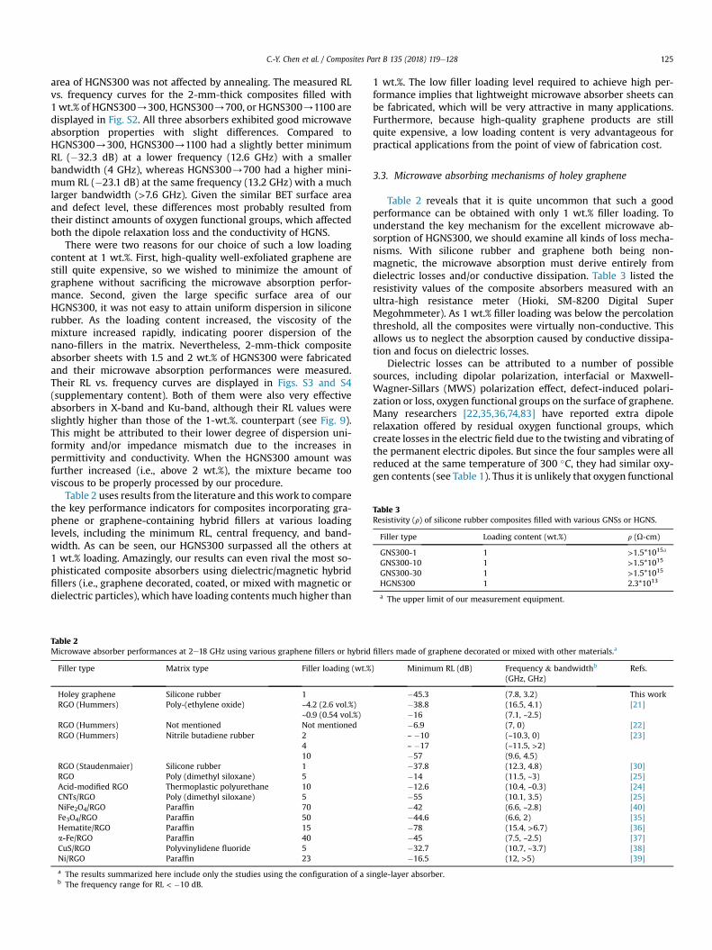
The degree of exfoliation and crystallinity of HGNS could becharacterized by XRD. In Fig. 2, natural graphite with a typicalinterlayer space of 0.34 nm exhibited a sharp (002) peak at2q ¼ 26.5�. After oxidation, the GO sample showed a characteristicpeak at a much smaller 2q angle of 11.5�, which corresponded to asignificantly enlarged interlayer distance from 0.34 to 0.78 nm dueto the formation of oxygen functional groups between graphitelayers. For GNS300-1, GNS300-10, GNS300-30, and HGNS300, the(002) peak disappeared totally as a result of a high degree ofexfoliation after the thermal exfoliation/reduction of GO.
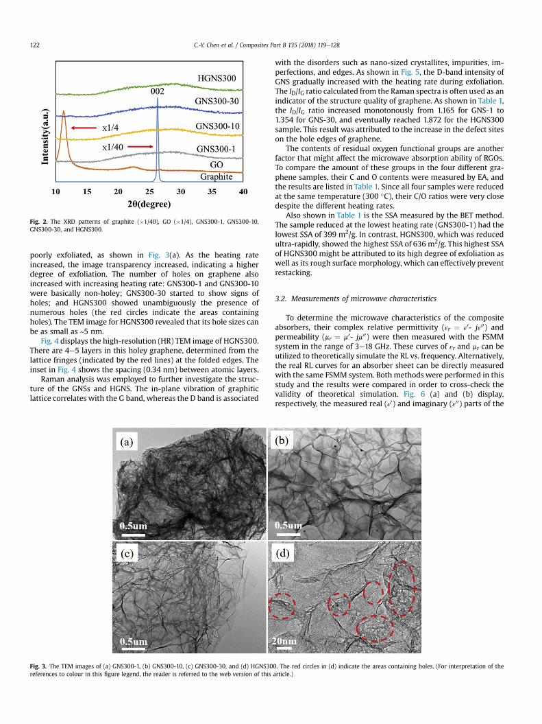
TEM images of the GNS and HGNS samples are shown in Fig. 3.All samples exhibited the distinct feature of numerous wrinklescommon to all thermally exfoliated Staudenmaier graphene.GNS300-1, which was reduced at the lowest heating rate, was very
igh-magnification image of the HGNS300 sample (the red circles reveal the outward-gend, the reader is referred to the web version of this article.)
Fig. 2. The XRD patterns of graphite (�1/40), GO (�1/4), GNS300-1, GNS300-10,GNS300-30, and HGNS300.
C.-Y. Chen et al. / Composites Part B 135 (2018) 119e128122
poorly exfoliated, as shown in Fig. 3(a). As the heating rateincreased, the image transparency increased, indicating a higherdegree of exfoliation. The number of holes on graphene alsoincreased with increasing heating rate: GNS300-1 and GNS300-10were basically non-holey; GNS300-30 started to show signs ofholes; and HGNS300 showed unambiguously the presence ofnumerous holes (the red circles indicate the areas containingholes). The TEM image for HGNS300 revealed that its hole sizes canbe as small as ~5 nm.
Fig. 4 displays the high-resolution (HR) TEM image of HGNS300.There are 4e5 layers in this holey graphene, determined from thelattice fringes (indicated by the red lines) at the folded edges. Theinset in Fig. 4 shows the spacing (0.34 nm) between atomic layers.
Raman analysis was employed to further investigate the struc-ture of the GNSs and HGNS. The in-plane vibration of graphiticlattice correlates with the G band, whereas the D band is associated
Fig. 3. The TEM images of (a) GNS300-1, (b) GNS300-10, (c) GNS300-30, and (d) HGNS30references to colour in this figure legend, the reader is referred to the web version of this
with the disorders such as nano-sized crystallites, impurities, im-perfections, and edges. As shown in Fig. 5, the D-band intensity ofGNS gradually increased with the heating rate during exfoliation.The ID/IG ratio calculated from the Raman spectra is often used as anindicator of the structure quality of graphene. As shown in Table 1,the ID/IG ratio increased monotonously from 1.165 for GNS-1 to1.354 for GNS-30, and eventually reached 1.872 for the HGNS300sample. This result was attributed to the increase in the defect siteson the hole edges of graphene.
The contents of residual oxygen functional groups are anotherfactor that might affect the microwave absorption ability of RGOs.To compare the amount of these groups in the four different gra-phene samples, their C and O contents were measured by EA, andthe results are listed in Table 1. Since all four samples were reducedat the same temperature (300 �C), their C/O ratios were very closedespite the different heating rates.
Also shown in Table 1 is the SSA measured by the BET method.The sample reduced at the lowest heating rate (GNS300-1) had thelowest SSA of 399 m2/g. In contrast, HGNS300, which was reducedultra-rapidly, showed the highest SSA of 636 m2/g. This highest SSAof HGNS300 might be attributed to its high degree of exfoliation aswell as its rough surface morphology, which can effectively preventrestacking.
3.2. Measurements of microwave characteristics
To determine the microwave characteristics of the compositeabsorbers, their complex relative permittivity (εr ¼ ε
0- jε00) andpermeability (mr ¼ m0- jm00) were then measured with the FSMMsystem in the range of 3e18 GHz. These curves of εr and mr can beutilized to theoretically simulate the RL vs. frequency. Alternatively,the real RL curves for an absorber sheet can be directly measuredwith the same FSMM system. Bothmethods were performed in thisstudy and the results were compared in order to cross-check thevalidity of theoretical simulation. Fig. 6 (a) and (b) display,respectively, the measured real (ε0) and imaginary (ε00) parts of the
0. The red circles in (d) indicate the areas containing holes. (For interpretation of thearticle.)
Fig. 4. HR-TEM image of HGNS300. The number of atomic layers are indicated by thered lines. The inset shows the spacing (0.34 nm) between atomic layers. (For inter-pretation of the references to colour in this figure legend, the reader is referred to theweb version of this article.)
Fig. 5. Raman spectra of GNS300-1, GNS300-10, GNS300-30, and HGNS300 samples.
Table 1Raman analysis, elemental analysis, and BET surface area analysis of GNS and HGNSsamples.
a The intensity ratio of D-band to G-band on Raman spectrum.b From elemental analysis.c BET specific surface area.
Fig. 6. Dispersion curves of the (a) real and (b) imaginary parts of the relativepermittivity for composites with 1 wt.% of GNS or HGNS fillers.
C.-Y. Chen et al. / Composites Part B 135 (2018) 119e128 123
relative permittivity for all of the 1-wt.% microwave absorbingcomposites. With GNS300s, HGNS300, and silicone rubber beingnon-magnetic, all of the composite absorbers had a m0 value of ~1and a negligible m00 (not shown). Consequently, their microwaveabsorbing capability should derive from the electric losses only.
Neat silicone rubber (not shown) has an ε0 value of ~3 and a
negligible ε00 (3e18 GHz).
ε0 and ε
00 are associated with the storage and dissipation ofelectric energy, respectively. As shown in Fig. 6 (a) and (b),HGNS300 performedmuch better in terms of both ε
0 and ε00 than all
other GNS300 samples at 1 wt.% loading. Its ε0 values ranged be-
tween 7.7 and 20.6, and its ε00, which is a critical factor for the
absorber performance, was in the range 2.3e3.2. Note that exces-sively large ε
0 and ε00 would cause high surface reflection due to a
large impedance mismatch between air and the dielectric. Thepermittivity values for our HGNS300/silicone rubber composite liewithin the range of acceptable impedance mismatch. For example,similar non-magnetic dielectric microwave absorbers have beenstudied in Refs. [21,23,24,30,80], and their permittivity valuesroughly lie within this range for the optimized performances.
Fig. 7 displays the dielectric loss tangents tandε (¼ ε00/ε0) for all of
the composites. Clearly HGNS300 exhibited a larger tandε than theother GNS samples, confirming that it had a higher dielectric lossthan the others. Moreover, its dielectric loss covered a wide fre-quency range (its loss tangent was greater than 0.2 from 4 to18 GHz).
Fig. 7. Dielectric loss tangents for all specimens.
C.-Y. Chen et al. / Composites Part B 135 (2018) 119e128124
Fig. 8 depicts the experimental RL vs. frequency curves, obtainedfrom direct measurement with the FSMM system, of all the com-posite sheets (2 mm thick) containing 1 wt.% of various graphene.RL (dB) is defined by: RL ¼ 10 log10Pr/Pi, where Pr and Pi are themeasured powers of the incident and reflected microwaves. Allspecimens except HGNS300 exhibited similar RL curves with aminimum of �7.9 to �8.3 dB at 16.5 GHz. These RL values areactually quite good considering that the loading level is so low.However, merely 1 wt.% of HGNS300 can offer an extraordinarilygood RL of �32.1 dB at 13.2 GHz, and the bandwidth of RL lessthan �10 dB (equivalent to 90% absorption [35,81,82]) was as largeas 5 GHz (from 11.3 to 16.3 GHz). These results suggest that theholey structure can significantly improve the microwave absorbingperformance of graphene.
The minimum value of RL and the resonance frequency can beadjusted by altering the absorber thickness. Theoretically, the RL atnormal incidence for an absorber layer with thickness, d, backed bya conductor can be calculated from the measured complex εr and mrversus frequency, f, by exploiting the following formula [77]:
Fig. 8. Experimentally measured RL vs. frequency for composites with 1 wt.% of GNS orHGNS fillers at a fixed thickness of 2 mm.
RLðdBÞ ¼ 20 log����zin � 1zin þ 1
����;
where zin is the normalized input impedance of the absorber sheetbacked by an ideal conductor. zin is defined as
zin ¼ffiffiffiffiffimrεr
rtanh
�j�2pfdc
� ffiffiffiffiffiffiffiffiffimrεr
p �;
where c is the speed of light in free space.The calculated theoretical RL curves for the composite filled
with 1 wt.% of HGNS300 with various thicknesses are depicted inFig. 9. We may compare the theoretical RL curve for thicknessd ¼ 2.0 mm (pink circles) with the corresponding experimentallymeasured RL curve (pink triangles, the one for 1 wt.% HGNS300) inFig. 8. Given the complexity of an EM absorption characterizationsystem, the theoretical and experimental RL curves matched quitewell in the trend, value, and resonant frequency. Fig. 9 clearlyshows that, as the thickness (d) increased, the absorption resonancedownshifted towards lower frequencies. At d ¼ 3.0 mm, an optimalRL of �45.3 dB was obtained at 7.8 GHz, and the absorptionbandwidth (for RL less than �10 dB, i.e., 90% absorption) amountedup to 3.2 GHz (from 6.5 to 9.7 GHz). Fig. 9 also suggests that EMabsorbers for a wide microwave frequency rangedfrom 5 to18 GHzdcan be fabricated using this composite material withd ¼ 2e4 mm. Given such a low content of microwave absorbingfillers, these RL values and bandwidths of the composite absorberare truly remarkable.
High-temperature post annealing can further remove the re-sidual oxygen functional groups on graphene, and consequentlymay change its microwave absorption properties. To investigatethis effect, we used three different temperatures (300, 700, and1100 �C) to prepare annealed HGNS300 samples, which werenamed HGNS300/300, HGNS300/700, and HGNS300/1100,respectively. The Raman spectra of the annealed samples are shownin Fig. S1 (supplementary content). Their ID/IG ratios (listed inTable S1) were nearly the same because the lattice defects werehardly affected at these temperatures. In contrast, the C/O atomicratio (also listed in Table S1) increased drastically (from 4.8 to 44.5)with increasing annealing temperature due to the removal of ox-ygen functional groups. Table S1 also reveals that the BET surface
Fig. 9. Calculated RL vs. frequency for the composite with 1 wt.% of HGNS300 atdifferent thicknesses.
Table 3Resistivity (r) of silicone rubber composites filled with various GNSs or HGNS.
Filler type Loading content (wt.%) r (U-cm)
GNS300-1 1 >1.5*1015a
GNS300-10 1 >1.5*1015
GNS300-30 1 >1.5*1015
HGNS300 1 2.3*1013
a The upper limit of our measurement equipment.
C.-Y. Chen et al. / Composites Part B 135 (2018) 119e128 125
area of HGNS300 was not affected by annealing. The measured RLvs. frequency curves for the 2-mm-thick composites filled with1wt.% of HGNS300/300, HGNS300/700, or HGNS300/1100 aredisplayed in Fig. S2. All three absorbers exhibited good microwaveabsorption properties with slight differences. Compared toHGNS300/300, HGNS300/1100 had a slightly better minimumRL (�32.3 dB) at a lower frequency (12.6 GHz) with a smallerbandwidth (4 GHz), whereas HGNS300/700 had a higher mini-mum RL (�23.1 dB) at the same frequency (13.2 GHz) with a muchlarger bandwidth (>7.6 GHz). Given the similar BET surface areaand defect level, these differences most probably resulted fromtheir distinct amounts of oxygen functional groups, which affectedboth the dipole relaxation loss and the conductivity of HGNS.
There were two reasons for our choice of such a low loadingcontent at 1 wt.%. First, high-quality well-exfoliated graphene arestill quite expensive, so we wished to minimize the amount ofgraphene without sacrificing the microwave absorption perfor-mance. Second, given the large specific surface area of ourHGNS300, it was not easy to attain uniform dispersion in siliconerubber. As the loading content increased, the viscosity of themixture increased rapidly, indicating poorer dispersion of thenano-fillers in the matrix. Nevertheless, 2-mm-thick compositeabsorber sheets with 1.5 and 2 wt.% of HGNS300 were fabricatedand their microwave absorption performances were measured.Their RL vs. frequency curves are displayed in Figs. S3 and S4(supplementary content). Both of them were also very effectiveabsorbers in X-band and Ku-band, although their RL values wereslightly higher than those of the 1-wt.%. counterpart (see Fig. 9).This might be attributed to their lower degree of dispersion uni-formity and/or impedance mismatch due to the increases inpermittivity and conductivity. When the HGNS300 amount wasfurther increased (i.e., above 2 wt.%), the mixture became tooviscous to be properly processed by our procedure.
Table 2 uses results from the literature and this work to comparethe key performance indicators for composites incorporating gra-phene or graphene-containing hybrid fillers at various loadinglevels, including the minimum RL, central frequency, and band-width. As can be seen, our HGNS300 surpassed all the others at1 wt.% loading. Amazingly, our results can even rival the most so-phisticated composite absorbers using dielectric/magnetic hybridfillers (i.e., graphene decorated, coated, or mixed with magnetic ordielectric particles), which have loading contents much higher than
Table 2Microwave absorber performances at 2e18 GHz using various graphene fillers or hybrid
a The results summarized here include only the studies using the configuration of a sib The frequency range for RL < �10 dB.
1 wt.%. The low filler loading level required to achieve high per-formance implies that lightweight microwave absorber sheets canbe fabricated, which will be very attractive in many applications.Furthermore, because high-quality graphene products are stillquite expensive, a low loading content is very advantageous forpractical applications from the point of view of fabrication cost.
3.3. Microwave absorbing mechanisms of holey graphene
Table 2 reveals that it is quite uncommon that such a goodperformance can be obtained with only 1 wt.% filler loading. Tounderstand the key mechanism for the excellent microwave ab-sorption of HGNS300, we should examine all kinds of loss mecha-nisms. With silicone rubber and graphene both being non-magnetic, the microwave absorption must derive entirely fromdielectric losses and/or conductive dissipation. Table 3 listed theresistivity values of the composite absorbers measured with anultra-high resistance meter (Hioki, SM-8200 Digital SuperMegohmmeter). As 1 wt.% filler loading was below the percolationthreshold, all the composites were virtually non-conductive. Thisallows us to neglect the absorption caused by conductive dissipa-tion and focus on dielectric losses.
Dielectric losses can be attributed to a number of possiblesources, including dipolar polarization, interfacial or Maxwell-Wagner-Sillars (MWS) polarization effect, defect-induced polari-zation or loss, oxygen functional groups on the surface of graphene.Many researchers [22,35,36,74,83] have reported extra dipolerelaxation offered by residual oxygen functional groups, whichcreate losses in the electric field due to the twisting and vibrating ofthe permanent electric dipoles. But since the four samples were allreduced at the same temperature of 300 �C, they had similar oxy-gen contents (see Table 1). Thus it is unlikely that oxygen functional
fillers made of graphene decorated or mixed with other materials.a
Fig. 11. Cole-Cole plot for the 1-wt.% HGNS300 composite absorber.
C.-Y. Chen et al. / Composites Part B 135 (2018) 119e128126
groups were the cause for the great differences in RL.There are two most noticeable features of HGNS300 compared
to the other samples: (1) its significantly higher ID/IG ratio, whichindicated a high density of defects; (2) its extremely high SSA,which might be attributed to its good resistance against restackingas a result of its rough surface morphology and outward-openinghole edges. Consequently, HGNS300's remarkable microwaveabsorbing performance at such a low loading content might beattributed to the following mechanisms: defect-induced losses,multiple reflection of microwave in between the surfaces of better-exfoliated graphene sheets, and enhanced MWS interfacialpolarization.
First of all, high defect density may significantly improve mi-crowave absorption. Several research groups have reported thatdefects [22,33,35,36,74e76] on the graphene surface are beneficialrather than harmful for microwave absorption applications becausethey offer extra loss mechanisms. Watts et al. [76] have found thatdefective CNTs displayed higher permittivity than graphitic CNTsbecause the defects acted as polarization centers, which wouldcause losses under the altering EM field. For our HGNS300, on theedges of numerous holes, there are plenty of dangling bonds andunsaturated coordination, which might give rise to orientationalpolarization [74]. Belavin et al. [84] have also reported that latticedefects on CNTs can create localized states near the Fermi level, andincident EM energy can be absorbed by the transition fromcontiguous states to the Fermi level [76]. Theoretical calculationshave predicted that on the zigzag edges of graphene nanoribbons,RGO, and nanographite, in the proximity of the Fermi level, lies alocalized edge state [85,86], whose existence were verified exper-imentally by near-edge x-ray absorption fine-structure spectrum[87e90] as well as ultraviolet photoelectron spectrum [88]. Tran-sition from the top of the valence band into the edge state byabsorbing a microwave photon is allowed quantum mechanicallybecause of the nonzero transition matrix element and the littleenergy required for this process. The abundant edge sites aroundthe holes on our HGNS may offer many such edge-derived states,which can enhance absorption of microwave.
Secondly, multiple reflections and scattering of microwave be-tween the graphene sheets can considerably lengthen the absorp-tion paths and hence increase the microwave absorption[22,23,32,83]. The highest SSA of HGNS300 as well as its anti-restacking property resulted in more interfaces between HGNSand thematrix, leading to enhancedmultiple reflections. Moreover,the numerous hole edges increased the scattering effectsignificantly.
Thirdly, the MWS interfacial polarization effect can offer addi-tional dielectric loss [25,35,36,74,81,83,91]. The highest degree of
Fig. 10. Schematic of possible microwav
exfoliation of HGNS led to the largest area of filler-matrix interfaces,which gave rise to strong MWS effect. This polarization effect wascaused by the accumulation of graphene's delocalized electrons atthe HGNS-silicone rubber interface when they were driven by theapplied electric field. While MWS effect is usually observed in theMHz range or below, in composites filled with nanocarbon-basedadditives, such as CNT/graphene [25], Fe3O4/RGO [35], Ag/RGO[91], and graphene nanoribbons [83], many researchers haveidentified its presence at GHz frequencies. These possible micro-wave absorption mechanisms in our HGNS300 composite absorberare schematically illustrated in Fig. 10.
Many researchers [25,35,36,38,74,83] have reported that thenumber of relaxation mechanisms in a dielectric material is re-flected in the number of semicircle segments on the ε
0eε00 curve, orthe Cole-Cole plot [92]. In Fig. 11, the Cole-Cole plot for the 1-wt.%HGNS300 composite absorber reveals the presence of three over-lapping semicircles, suggesting that there were three dielectric lossmechanisms involved in its microwave absorption. This supportsour speculation of the three aforementioned mechanisms in ourcomposite absorber.
We believe the three loss mechanisms, namely, high defectdensity, increased multiple reflections and scattering, andenhanced MWS effect, jointly brought about the high RL and largeabsorption bandwidth for HGNS300 at 1 wt.% loading.
e absorption mechanisms in HGNS.
C.-Y. Chen et al. / Composites Part B 135 (2018) 119e128 127
4. Conclusions
A comparison of the microwave absorption performance of sil-icone rubber absorbers filled with various graphene productsproduced by reducing GO with different heating rates was made.Holey graphene (HGNS300) prepared by a facile ultra-rapid heatingmethod exhibited considerably higher increases in the dielectricpermittivity, as well as RL improvements over the other graphenesamples prepared at lower heating rates. With a very low loadinglevel (1 wt.%) of HGNS300, the experimentally measured RL was aslow as �32.1 dB at 13.2 GHz for an absorber thickness of 2.0 mm.The bandwidth (RL < 10 dB) of this absorber sheet was as wide as5.0 GHz (from 11.3 to 16.3 GHz). Moreover, calculations revealedthat an optimum RL of �45.3 dB can be attained at 7.8 GHz using athickness of 3.0 mm. Comparison was made among the materialproperties of all samples, including surface morphology, Ramanspectrum, C/O ratio, and SSA, in order to determine the causesleading to the extraordinary performance of HGNS300 at such a lowloading level. The results indicated that HGNS300 possessed thehighest density of defects and the largest SSA. The largest SSAindicated that it had the highest degree of exfoliation as well as thebest anti-restacking ability, which was probably due to its roughestsurface morphology and the outward opening hole edges. Conse-quently, defect-induced losses combined with the increased mul-tiple reflections/scattering and MWS interfacial polarizationresulted in the significantly enhanced microwave absorption. Theholey graphene microwave absorber shows great potential forpractical applications, given the low processing cost and the lowfiller loading required for high performance.
Acknowledgements
This study is sponsored byMinistry of Science and Technology ofTaiwan under Grants No. MOST-105-2221-E-155-017, MOST-106-2623-E-606-003-D, and MOST-106-2221-E-155-016, National De-fense Industrial Development Foundation, and Chemical SystemResearch Division at National Chung Shan Institute of Science andTechnology under Grant No. XD05011P-CS.
Appendix A. Supplementary data
Supplementary data related to this article can be found athttps://doi.org/10.1016/j.compositesb.2017.10.001.
References
[1] Liu X, Zhang Z, Wu Y. Absorption properties of carbon black/silicon carbidemicrowave absorbers. Compos Part B 2011;42:326e9.
[2] Li WP, Zhu LQ, Gu J, Liu HC. Microwave absorption properties of fabric coatedabsorbing material using modified carbonyl iron power. Compos Part B2011;42:626e30.
[3] Pokharel P, Truong QT, Lee DS. Multi-step microwave reduction of graphiteoxide and its use in the formation of electrically conductive graphene/epoxycomposites. Compos Part B 2014;64:187e93.
[4] Wu W, Zhai Y, Zhang Y, Ren W. Mechanical and microwave absorbing prop-erties of in situ prepared hydrogenated acrylonitrileebutadiene rubber/rareearth acrylate composites. Compos Part B 2014;56:497e503.
[5] Liu Y, Song D, Wu C, Leng J. EMI shielding performance of nanocompositeswith MWCNTs, nanosized Fe3O4 and Fe. Compos Part B 2014;63:34e40.
[6] Joshi A, Bajaj A, Singh R, Anand A, Alegaonkar PS, Datar S. Processing of gra-phene nanoribbon based hybrid composite for electromagnetic shielding.Compos Part B 2015;69:472e7.
[7] Tang H, Jian X, Wu B, Liu S, Jiang Z, Chen X, et al. Fe3C/helical carbon nanotubehybrid: facile synthesis and spin induced enhancement in microwave-absorbing properties. Compos Part B 2016;107:51e8.
[8] Al-Ghamdi AA, Al-Hartomy OA, Al-Solamy FR, Dishovsky N, Malinova P,Atanasova G, et al. Conductive carbon black/magnetite hybrid fillers in mi-crowave absorbing composites based on natural rubber. Compos Part B2016;96:231e41.
[9] Wu J, Chen J, Zhao Y, Liu W, Zhang W. Effect of electrophoretic condition on
the electromagnetic interference shielding performance of reduced grapheneoxide-carbon fiber/epoxy resin composites. Compos Part B 2016;105:167e75.
[10] Bibi M, Abbas SM, Ahmad N, Muhammad B, Iqbal Z, Rana UA, et al. Micro-waves absorbing characteristics of metal ferrite/multiwall carbon nanotubesnanocomposites in X-band. Compos Part B 2017;114:139e48.
[11] Mondal S, Ganguly S, Das P, Khastgir D, Das NC. Low percolation threshold andelectromagnetic shielding effectiveness of nano-structured carbon basedethylene methyl acrylate nanocomposites. Compos Part B 2017;119:41e56.
[12] Galindo B, Benedito A, Gimenez E, Compa~n V. Comparative study between themicrowave heating efficiency of carbon nanotubes versus multilayer gra-phene in polypropylene nanocomposites. Compos Part B 2016;98:330e8.
[13] Chen Y, Zhang A, Ding L, Liu Y, Lu H. A three-dimensional absorber hybridwith polar oxygen functional groups of MWNTs/graphene with enhancedmicrowave absorbing properties. Compos Part B 2017;108:386e92.
[14] Lee SE, Choi O, Hahn HT. Microwave properties of graphite nanoplatelet/epoxy composites. J Appl Phys 2008;104(3):033705.
[15] Micheli D, Vricella A, Pastore R, Marchetti M. Synthesis and electromagneticcharacterization of frequency selective radar absorbing materials using carbonnanopowders. Carbon 2014;77:756e74.
[16] Wu KH, Ting TH, Wang GP, Ho WD, Shih CC. Effect of carbon black content onelectrical and microwave absorbing properties of polyaniline/carbon blacknanocomposites. Polym Degrad Stab 2008;93(2):483e8.
[17] Vinayasree S, Soloman MA, Sunny V, Mohanan P, Kurian P, Anantharaman MR.A microwave absorber based on strontium ferriteecarbon blackenitrile rub-ber for S and X-band applications. Compos Sci Technol 2013;82:69e75.
[18] Kim JB, Lee SK, Kim CG. Comparison study on the effect of carbon nano ma-terials for single-layer microwave absorbers in X-band. Compos Sci Technol2008;68(14):2909e16.
[19] Qing Y, Wang X, Zhou Y, Huang Z, Luo F, Zhou W. Enhanced microwave ab-sorption of multi-walled carbon nanotubes/epoxy composites incorporatedwith ceramic particles. Compos Sci Technol 2014;102:161e8.
[20] Bhattacharya P, Sahoo S, Das CK. Microwave absorption behaviour of MWCNTbased nanocomposites in X-band region. Express Polym Lett 2013;7(3):212e23.
[21] Bai X, Zhai Y, Zhang Y. Green approach to prepare graphene-based compositeswith high microwave absorption capacity. J Phys Chem C 2011;115(23):11673e7.
[22] Wang C, Han X, Xu P, Zhang X, Du Y, Hu S, et al. The electromagnetic propertyof chemically reduced graphene oxide and its application as microwaveabsorbing material. Appl Phys Lett 2011;98(7):072906.
[23] Singh VK, Shukla A, Patra MK, Saini L, Jani RK, Vadera SR, et al. Microwaveabsorbing properties of a thermally reduced graphene oxide/nitrile butadienerubber composite. Carbon 2012;50(6):2202e8.
[24] Bhattacharya P, Das CK, Kalra SS. Graphene and MWCNT: potential candidatefor microwave absorbing materials. J Mater Sci Res 2012;1(2):126e32.
[25] Kong L, Yin X, Zhang Y, Liu X, Cheng L, Zhang L. Electromagnetic wave ab-sorption properties of graphene modified with carbon nanotube/poly(-dimethyl siloxane) composites. Carbon 2014;73:185e93.
[26] Gogoi JP, Bhattacharyya NS, Raju KCJ. Synthesis and microwave character-ization of expanded graphite/novolac phenolic resin composite for microwaveabsorber applications. Compos Part B 2011;42:1291e7.
[27] Cao MS, Song WL, Hou ZL, Wen B, Yuan J. The effects of temperature andfrequency on the dielectric properties, electromagnetic interference shieldingand microwave-absorption of short carbon fiber/silica composites. Carbon2010;48:788e96.
[28] Cao MS, Yang J, Song WL, Zhang DQ, Wen B, Jin HB, et al. Ferroferric oxide/multiwalled carbon nanotube vs polyaniline/ferroferric oxide/multiwalledcarbon nanotube multiheterostructures for highly effective microwave ab-sorption. ACS Appl Mater Interfaces 2012;4(12):6949e56.
[29] Lu MM, Cao MS, Chen YH, Cao WQ, Liu J, Shi HL, et al. Multiscale Assembly ofgrape-like ferroferric oxide and carbon-nanotubes: a smart absorber proto-type varying temperature to tune intensities. ACS Appl Mater Interfaces2015;7(34):19408e15.
[30] Chen CY, Pu NW, Liu YM, Huang SY, Wu CH, Ger MD, et al. Remarkable mi-crowave absorption performance of graphene at a very low loading ratio.Compos Part B 2017;114:395e403.
[31] Liang J, Wang Y, Huang Y, Ma Y, Liu Z, Cai J, et al. Electromagnetic interferenceshielding of graphene/epoxy composites. Carbon 2009;47(3):922e5.
[32] Wen B, Wang XX, Cao WQ, Shi HL, Lu MM, Wang G, et al. Reduced grapheneoxides: the thinnest and most lightweight materials with highly efficientmicrowave attenuation performances of the carbon world. Nanoscale 2014;6:5754e61.
[33] Wen B, Cao M, Lu M, Cao W, Shi H, Liu J, et al. Reduced graphene oxides: light-weight and high-efficiency electromagnetic interference shielding at elevatedtemperatures. Adv Mater 2014;26(21):3484e9.
[34] Cao WQ, Wang XX, Yuan J, Wang WZ, Cao MS. Temperature dependent mi-crowave absorption of ultrathin graphene composites. J Mater Chem C2015;3(38):10017e22.
[35] Zong M, Huang Y, Zhao Y, Sun X, Qu C, Luo D, et al. Facile preparation, highmicrowave absorption and microwave absorbing mechanism of RGOeFe3O4composites. RSC Adv 2013;3(45):23638e48.
[36] Chen D, Wang GS, He S, Liu J, Guo L, Cao MS. Controllable fabrication of mono-dispersed RGO-hematite nanocomposites and their enhanced wave absorp-tion properties. J Mater Chem A 2013;1:5996e6003.
[37] Zhao X, Zhang Z, Wang L, Xi K, Cao Q, Wang D, et al. Excellent microwave
C.-Y. Chen et al. / Composites Part B 135 (2018) 119e128128
absorption property of graphene-coated Fe nanocomposites. Sci Rep 2013;3:3421.
[38] Zhang XJ, Wang GS, Wei YZ, Guo L, Cao MS. Polymer-composite with highdielectric constant and enhanced absorption properties based on graphene-CuS nanocomposites and polyvinylidene fluoride. J Mater Chem A 2013;1:12115e22.
[39] Fang JJ, Li SF, Zha WK, Cong HY, Chen JF, Chen ZZ. Microwave absorbingproperties of nickel-coated graphene. J Inorg Mater 2011;26(5):467e71.
[40] He JZ, Wang XX, Zhang YL, Cao MS. Small magnetic nanoparticles decoratingreduced graphene oxides to tune the electromagnetic attenuation capacity.J Mater Chem C 2016;4:7130e40.
[41] Wang C, Li D, Too CO, Wallace GG. Electrochemical properties of graphenepaper electrodes used in lithium batteries. Chem Mater 2009;21(13):2604e6.
[42] Abouimrane A, Compton OC, Amine K, Nguyen ST. Non-annealed graphenepaper as a binder-free anode for lithium-ion batteries. J Phys Chem2010;114(29):12800e4.
[43] Stoller MD, Park S, Zhu Y, An J, Ruoff RS. Graphene-based ultracapacitors.Nano Lett 2008;8(10):3498e502.
[44] Peng YY, Liu YM, Chang JK, Wu CH, Ger MD, Pu NW, et al. A facile approach toproduce holey graphene and its application in supercapacitors. Carbon2015;81:347e56.
[45] Mao S, Wen Z, Kim H, Lu G, Hurley P, Chen J. A general approach to one-potfabrication of crumpled graphene-based nanohybrids for energy applications.ACS Nano 2012;6(8):7505e13.
[46] Luo J, Zhao X, Wu J, Jang HD, Kung HH, Huang J. Crumpled graphene-encapsulated Si nanoparticles for lithium ion battery anodes. J Phys ChemLett 2012;3(13):1824e9.
[47] Luo J, Jang HD, Huang J. Effect of sheet morphology on the scalability ofgraphene-based ultracapacitors. ACS Nano 2013;7(2):1464e71.
[48] Xi K, Kidambi PR, Chen R, Gao C, Peng X, Ducati C, et al. Binder free three-dimensional sulphur/few-layer graphene foam cathode with enhancedhigh-rate capability for rechargeable lithium sulphur batteries. Nanoscale2014;6:5746e53.
[50] Wu CH, Pu NW, Wu PJ, Peng YY, Shih CN, Chen CY, et al. High-electrical-re-sistivity thermally-conductive phase change materials prepared by addingnanographitic fillers into paraffin. Microelectron Eng 2015;138:91e6.
[51] Zhao X, Hayner CM, Kung MC, Kung HH. In-plane vacancy-enabled high-po-wer Siegraphene composite electrode for lithium-ion batteries. Adv EnergyMater 2011;1(6):1079e84.
[52] Wu ZS, Ren W, Wen L, Gao L, Zhao J, Chen Z, et al. Graphene anchored withCo3O4 nanoparticles as anode of lithium ion batteries with enhancedreversible capacity and cyclic performance. ACS Nano 2010;4(6):3187e94.
[53] Xing L, Cui C, Ma C, Xue X. Facile synthesis of a-MnO2/graphene nano-composites and their high performance as lithium-ion battery anode. MaterLett 2011;65(14):2104e6.
[54] Zhu X, Zhu Y, Murali S, Stoller MD, Ruoff RS. Nanostructured reduced gra-phene oxide/Fe2O3 composite as a high-performance anode material forlithium ion batteries. ACS Nano 2011;5(4):3333e8.
[55] Zhao B, Ma C, Liang L, GuoW, Fan B, Guo X, et al. An impedance match methodused to tune the electromagnetic wave absorption properties of hierarchicalZnO assembled by porous nanosheets. CrystEngComm 2017;19:3640e8.
[56] Zhao B, Zhao W, Shao G, Fan B, Zhang R. Corrosive synthesis and enhancedelectromagnetic absorption properties of hollow porous Ni/SnO2 hybrids.Dalton Trans 2015;44:15984e93.
[57] Zhao B, Guo X, Zhou Y, Su T, Ma C, Zhang R. Constructing hierarchical hollowCuS microspheres via a galvanic replacement reaction and their use as wide-band microwave absorbers. CrystEngComm 2017;19:2178e86.
[58] Zhao B, Fan B, Xu Y, Shao G, Wang X, Zhao W, et al. Preparation of honeycombSnO2 foams and configuration-dependent microwave absorption features.ACS Appl Mater Interfaces 2015;7:26217e25.
[59] Zhao B, Shao G, Fan B, Zhao W, Xie Y, Zhang R. Synthesis of flower-like CuShollow microspheres based on nanoflakes self-assembly and their microwaveabsorption properties. J Mater Chem A 2015;3:10345e52.
[60] Zhao B, Guo X, Zhao W, Deng J, Shao G, Fan B, et al. Yolk�shell Ni@SnO2composites with a designable interspace to improve the electromagneticwave absorption properties. ACS Appl Mater Interfaces 2016;8:28917e25.
[61] Zhao B, Guo X, Zhao W, Deng J, Fan B, Shao G, et al. Facile synthesis ofyolkeshell Ni@void@SnO2(Ni3Sn2) ternary composites via galvanic replace-ment/Kirkendall effect and their enhanced microwave absorption properties.Nano Res 2017;10(1):331e43.
[62] Zhang Y, Huang Y, Zhang T, Chang H, Xiao P, Chen H, et al. Broadband andtunable high-performance microwave absorption of an ultralight and highlycompressible graphene foam. Adv Mater 2015;27(12):2049e53.
[63] Chen Z, Xu C, Ma C, Ren W, Cheng HM. Lightweight and flexible graphenefoam composites for high-performance electromagnetic interference shield-ing. Adv Mater 2013;25(9):1296e300.
[64] Zhao D, Wang L, Yu P, Zhao L, Tian C, Zhou W, et al. From graphite to porousgraphene-like nanosheets for high rate lithium-ion batteries. Nano Res
2015;8(9):2998e3010.[65] Cao H, Zhou X, Zheng C, Liu Z. Metal etching method for preparing porous
graphene as high performance anode material for lithium-ion batteries. Car-bon 2015;89:41e6.
[66] Zhao X, Hayner CM, Kung MC, Kung HH. Flexible holey graphene paperelectrodes with enhanced rate capability for energy storage applications. ACSNano 2011;5(11):8739e49.
[67] Fang Y, Lv Y, Che R, Wu H, Zhang X, Gu D, et al. Two-dimensional mesoporouscarbon nanosheets and their derived graphene nanosheets: synthesis andefficient lithium ion storage. J Am Chem Soc 2013;135(4):1524e30.
[68] Sun L, Tian C, Li M, Meng X, Wang L, Wang R, et al. From coconut shell toporous graphene-like nanosheets for high-power supercapacitors. J MaterChem A 2013;1:6462e70.
[69] Xu Y, Chen CY, Zhao Z, Lin Z, Lee C, Xu X, et al. Solution processable holeygraphene oxide and its derived macrostructures for high-performancesupercapacitors. Nano Lett 2015;15(7):4605e10.
[70] Ding B, Yuan C, Shen L, Xu G, Nie P, Lai Q, et al. Chemically tailoring thenanostructure of graphene nanosheets to confine sulfur for high-performancelithium-sulfur batteries. J Mater Chem A 2013;1:1096e101.
[71] Sui ZY, Meng QH, Li JT, Zhu JH, Cui Y, Han BH. High surface area porous car-bons produced by steam activation of graphene aerogels. J Mater Chem A2014;2:9891e8.
[72] Pan D, Wang S, Zhao B, Wu M, Zhang H, Wang Y, et al. Li storage properties ofdisordered graphene nanosheets. Chem Mater 2009;21:3136e42.
[73] Wang H, Zhang C, Liu Z, Wang L, Han P, Xu H, et al. Nitrogen-doped graphenenanosheets with excellent lithium storage properties. J Mater Chem 2011;21:5430e4.
[74] Wang GS, Zhang XJ, Wei YZ, He S, Guo L, Cao MS. Polymer composites withenhanced wave absorption properties based on modified graphite and poly-vinylidene fluoride. J Mater Chem A 2013;1:7031e6.
[75] Zhang XF, Dong XL, Huang H, Wang DK, Lv B, Lei JP. High permittivity fromdefective carbon-coated Cu nanocapsules. Nanotechnology 2007;18(27):275701.
[76] Watts PCP, Hsu WK, Barnes A, Chambers B. High permittivity from defectivemultiwalled carbon nanotubes in the X-band. Adv Mater 2003;15(7e8):600e3.
[77] Sadasivuni KK, Ponnamma D, Kim J, Thomas S. Graphene-based polymernanocomposites in electronics. Springer; 2015. p. 307e43.
[78] Ghodgaonkar DK, Ali NA. Microwave nondestructive testing of compositematerials using free-space microwave measurement techniques. In: 15thworld conference on non-destructive testing, Rome, Italy; 2000. p. 15e21.
[79] McAllister MJ, Li JL, Adamson DH, Schniepp HC, Abdala AA, Liu J, et al. Singlesheet functionalized graphene by oxidation and thermal expansion ofgraphite. Chem Mater 2007;19:4396e404.
[80] Tang N, Zhong W, Au C, Yang Y, Han M, Lin K, et al. Synthesis, microwaveelectromagnetic, and microwave absorption properties of twin carbonnanocoils. J Phys Chem C 2008;112(49):19316e23.
[81] Wang Y, Wang L, Wu H. Enhanced microwave absorption properties of a-Fe2O3-filled ordered mesoporous carbon nanorods. Materials 2013;6(4):1520e9.
[82] Yang Y, Liu X, Yang Y, Xiao W, Li Z, Xue D, et al. Synthesis of nonstoichiometriczinc ferrite nanoparticles with extraordinary room temperature magnetismand their diverse applications. J Mater Chem C 2013;1(16):2875e85.
[83] Gupta TK, Singh BP, Singh VN, Teotia S, Singh AP, Elizabeth I, et al. MnO2decorated graphene nanoribbons with superior permittivity and excellentmicrowave shielding properties. J Mater Chem A 2014;2(12):4256e63.
[84] Belavin VV, Okotrub AV, Bulusheva LG. A study of the influence of structuralimperfection on the electronic structure of carbon nanotubes by x-ray spec-troscopy and quantum-chemical methods. Phys Solid State 2002;44(4):663e5.
[85] Nakada K, Fujita M, Dresselhaus G, Dresselhaus MS. Edge state in grapheneribbons: nanometer size effect and edge shape dependence. Phys Rev B1996;54:17954e61.
[86] Maruyama M, Kusakabe K. Theoretical prediction of synthesis methods tocreate magnetic nanographite. J Phys Soc Jpn 2004;73:656e63.
[87] Joly VLJ, et al. Observation of magnetic edge state in graphene nanoribbons.Phys Rev B 2010;81:245428.
[88] Entani S, Ikeda S, Kiguchi M, Saiki K, Yoshikawa G, Nakai I, et al. Growth ofnanographite on Pt(111) and its edge state. Appl Phys Lett 2006;88(15):153126.
[89] Zhan D, Ni Z, Chen W, Sun L, Luo Z, Lai L, et al. Electronic structure of graphiteoxide and thermally reduced graphite oxide. Carbon 2011;49:1362e6.