Compound matrix partitioning and modification for the solution of branched autotransformer traction feeds Y.Cai M.R.lrving S.H.Case Indexing terms: Autotransformer truck jeed, AC traction jeed~s, Matrix partitioning algorithm Abstract: The increasing use of autotransformer feed schemes in AC electrified railways, as a result of their obvious advantages, motivates a detailed analysis of the behaviour of these systems. A novel compound matrix partitioning and modification method for the solution of a branched autotransformer feed system is presented. The introduction of branch lines in the autotransformer feed model has stimulated the development of a new solution technique which is very well matched to the problem formation. Results are cited which indicate that the proposed method can achieve a very efficient and reliable solution. List of principal symbols [a = conductor branch impedance matrix [ Yl = conductor nodal admittance matrix [A = conductor branch current vector [Jl = conductor nodal injected current vector [VI = conductor nodal voltage vector k = branch line connection node on trunk line n = number of trunk line nodes rn = number of branch line nodes t = node sequence number A = derived compound admittance matrix [a] = submatrix block of the inverse of A B, D = partitioned compound coefficient matrices C, E = partitioned compound right-hand-side vectors Z = compound identity matrix 1 Introduction Among the various AC traction power supply schemes, one approach which is commonly used in recent rail- 0 IEE, 1996 IEE Proceedings online no. 19960375 Paper first received 1st November 1995 and in revised form 6th February 1996 Dr. Y. Cai and Prof. M.R. Irving are with the Department of Electrical Engineering and Electronics, Brunel University, Uxbridge, Middlesex UB3 3PH, UK S.H. Case is with Balfour Kilpatrick Limited (a BICC company), Power Construction Division, PO Box 12, Acornfield Road, Kirkby, Liverpool L33 7TY, UK IEE Proc.-Electr. Power Appl., Vol. 143, No. 3, May I996 way electrification projects around the world is 2 x 25 kV autotransformer (AT) feeding. This combines the advantage of higher voltage power transmission, hence increased substation spacing, with the convenience of using standard 25 kV traction equipment. The longer feed sections make the AT system suitable for territory with few high voltage power sources and require less traction substations to be installed. The 50125kV autotransformers are installed typically at 1 Okm inter- vals along a line, and their windings are connected between the overhead catenary and return feeder, hav- ing a centre tap connected to rails and earth. The cur- rents flowing through catenary and return feeder for most loading conditions are almost equal (to satisfy core ampere-turn balances), which gives good telecom- munication interference suppression. One particular feature of AT feeding is that because of the number of autotransformers connected to the system at intervals, each one contributes a proportion to the train current. The current distribution between the catenary, rails and feeder is very complex, and the accurate calculation of voltage regulation in the system is consequently also difficult. The electromagnetic cou- pling which exists between the conductors makes the problem even more complicated. Furthermore, the par- allel-connected autotransformers introduce lumped impedances at intervals along the line. All these factors result in some difficulties in modelling AT feeding within a conventional AC traction power system simu- lator. To analyse the distribution of voltages and currents in an unbranched AT feed, a multiconductor approach is adopted. The method is based on the CCITT guide- lines, and was also used by Fujie [l] and Chan et al. [2] in their research work. It considers the power distribu- tion network in terms of self and mutual impedances between groups of conductors, and self and mutual admittances at conductor nodes between adjacent sub- sections. The admittance of fixed equipment at specific locations and the admittance between rail and ground are also determined. The multiconductor method sub- divides a €eed section into incremental cells and uses matrix quantities to represent the impedance and admittance of conductors and components in each cell. The derived compound matrix has nonzero blocks only on the diagonal plus and minus one column, conse- quently the procedures for LU decomposition [3] can be encoded very concisely with the result that the whole solution can be accomplished much faster, and 25 1
Transcript
Compound matrix partitioning and modification for the solution of branched autotransformer traction feeds
Abstract: The increasing use of autotransformer feed schemes in AC electrified railways, as a result of their obvious advantages, motivates a detailed analysis of the behaviour of these systems. A novel compound matrix partitioning and modification method for the solution of a branched autotransformer feed system is presented. The introduction of branch lines in the autotransformer feed model has stimulated the development of a new solution technique which is very well matched to the problem formation. Results are cited which indicate that the proposed method can achieve a very efficient and reliable solution.
List of principal symbols
[a = conductor branch impedance matrix [ Yl = conductor nodal admittance matrix [A = conductor branch current vector [Jl = conductor nodal injected current vector [VI = conductor nodal voltage vector k = branch line connection node on trunk line n = number of trunk line nodes rn = number of branch line nodes t = node sequence number A = derived compound admittance matrix [a] = submatrix block of the inverse of A B, D = partitioned compound coefficient matrices C, E = partitioned compound right-hand-side vectors Z = compound identity matrix
1 Introduction
Among the various AC traction power supply schemes, one approach which is commonly used in recent rail-
0 IEE, 1996 IEE Proceedings online no. 19960375 Paper first received 1st November 1995 and in revised form 6th February 1996 Dr. Y. Cai and Prof. M.R. Irving are with the Department of Electrical Engineering and Electronics, Brunel University, Uxbridge, Middlesex UB3 3PH, UK S.H. Case is with Balfour Kilpatrick Limited (a BICC company), Power Construction Division, PO Box 12, Acornfield Road, Kirkby, Liverpool L33 7TY, UK
IEE Proc.-Electr. Power Appl., Vol. 143, No. 3, May I996
way electrification projects around the world is 2 x 25 kV autotransformer (AT) feeding. This combines the advantage of higher voltage power transmission, hence increased substation spacing, with the convenience of using standard 25 kV traction equipment. The longer feed sections make the AT system suitable for territory with few high voltage power sources and require less traction substations to be installed. The 50125kV autotransformers are installed typically at 1 Okm inter- vals along a line, and their windings are connected between the overhead catenary and return feeder, hav- ing a centre tap connected to rails and earth. The cur- rents flowing through catenary and return feeder for most loading conditions are almost equal (to satisfy core ampere-turn balances), which gives good telecom- munication interference suppression.
One particular feature of AT feeding is that because of the number of autotransformers connected to the system at intervals, each one contributes a proportion to the train current. The current distribution between the catenary, rails and feeder is very complex, and the accurate calculation of voltage regulation in the system is consequently also difficult. The electromagnetic cou- pling which exists between the conductors makes the problem even more complicated. Furthermore, the par- allel-connected autotransformers introduce lumped impedances at intervals along the line. All these factors result in some difficulties in modelling AT feeding within a conventional AC traction power system simu- lator.
To analyse the distribution of voltages and currents in an unbranched AT feed, a multiconductor approach is adopted. The method is based on the CCITT guide- lines, and was also used by Fujie [l] and Chan et al. [2] in their research work. It considers the power distribu- tion network in terms of self and mutual impedances between groups of conductors, and self and mutual admittances at conductor nodes between adjacent sub- sections. The admittance of fixed equipment at specific locations and the admittance between rail and ground are also determined. The multiconductor method sub- divides a €eed section into incremental cells and uses matrix quantities to represent the impedance and admittance of conductors and components in each cell. The derived compound matrix has nonzero blocks only on the diagonal plus and minus one column, conse- quently the procedures for LU decomposition [3] can be encoded very concisely with the result that the whole solution can be accomplished much faster, and
25 1
in much less storage. By solving these compound matrix equations, the conductor node voltages and the currents between adjacent nodes can be obtained.
This paper presents a novel compound matrix parti- tioning and modification method for solving an AT feeding system with branch lines. The multiconductor approach is also applied to form compound matrix equations describing voltage and current relationships for the trunk and branch lines. The separate solutions for these lines are achieved by partitioning the matrix into submatrices. The branch joint related blocks of the partitioned compound submatrices are modified to split the trunk and branch lines into two independent sub- systems. The method takes full advantage of the sparse structure of compound matrix equations by applying the block tridiagonal LU decomposition to the solu- tions of trunk and branch line subsystems, respectively. Results are presented which indicate that for AT feed- ing with branches the proposed method in conjunction with LU decomposition can achieve a very efficient and reliable solution.
2
AC railway feeding schemes are typically sectionalised by phase breaks at the traction substations and at par- alleling stations roughly midway between substations. Each power feed can thus be considered separately for calculation purposes. In the representation of an AT feed section only one branch line is assumed to be con- nected with a sectional trunk line. A branched multi- conductor system is illustrated in Fig. 1.
Representation of branched AT feed
k-1 [ I lk k [l]k+l k+l n A , - - ) I + ,
0 A I
' U '
ground
Fig. 1 Representation of branched multiconductor system
In the diagram, node k indicates the connecting point of the trunk and branch lines. The nodes and branches are defined by dividing parallel conductors into n cells on the trunk line and m cells on the branch line. These cells are not necessarily equal in length to allow flexi- bility in the position of nodes. The node admittances and branch impedances of each cell can be represented in matrix form as [U and [a. Vectors [A, [U and [A, respectively, define the branch currents, node voltages and nodal injected currents in the cell. These matrix quantities constitute the blocks of the compound matrix equations representing the branched multicon- ductor system. It is evident that the network model is greatly simplified by means of compound impedances or admittances. The concept is based on the use of matrix quantities to represent the impedances and admittances in the network. The laws and equations of ordinary networks all remain valid for compound net- works by simply replacing scalar quantities by the appropriate matrices.
Physical structure in the branched AT feed model can be utilised by decomposition into two separate lines which can then be solved individually and their
252
solutions recombined to achieve the solution of the overall problem. The interconnection between the two lines must be taken into account and will subsequently result in the modification of related block elements for both lines. To achieve the physical system decomposi- tion the sequence of the numbering scheme for subdi- vided cells is ordered from the trunk line to the branch line. Each subdivided cell in the feeding section is num- bered consecutively from the left-hand side to the right- hand side of the trunk line and then downwards from the branch line cell nearest to the junction.
3 Compound admittance matrix formation
A unique mesh equation describes the currents in each cell. In a similar manner, a nodal equation describes the voltages at each node. At the kth cell (between nodes k - 1 and k), this may be written as:
and for the branch joint node k we have the nodal equation
[Zlk . [ I l k = [VI,-1 - [VIk (1)
[ Y ] k [VI, = [ I l k - [I]~C+I - [I]n+1 + [ J ] k (2) If p is the total number of conductors, [Zl and [ r] are p x p square matrices. Vectors [A, [U and [A have the same order p . The subscripts k - 1, k, k + 1 and n + 1 represent different subsections or nodes. Mesh equa- tions similar to eqn. 1 can be written for cells k + l and n + 1 to give expressions for currents and [Anil. Substituting for the branch current vectors [Ilk, and into eqn. 2 gives
- [ZI,'. [VI,-, + [ZI,' + [Ylk + [ZI& + [ Z 1 4 . [VI, ( - [zI;:~. [ ~ I k + l - Ezjii:, ' [ ~ I n + l = [ J j k
( 3 ) Similarly, the loop and nodal equations which describe currents at the first branch subsection n + 1 and the second n + 2 and voltages at the first branch node n + 1 are:
IEE Proc.-Elecir. Power Appl., Vol. 143, No. 3, M a y I996
The nodal voltage equations at the branch joint node, the first branch line node and the three terminal nodes have been derived, and a general equation representing the remaining nodes in both trunk and branch lines can alco be written as
where t indicates the circuit nodes from 1 to n + m ~ 1 excluding the nodes k and n + 1 By enumerating cell nodes from 0 to n, and then from n + 1 to n t m, the nodal voltage equations can be arranged into a com- pound matrix form. The voltages and currents in each cell are subsequently obtained by solving matrix equa- tions with the general form [A][ VI = [A.
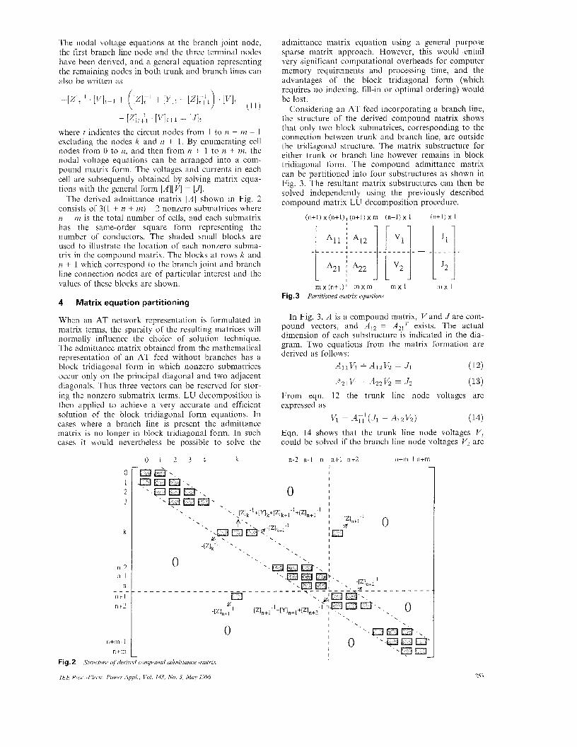
'The derived admittance matrix [A] shown in Fig. 2 consists of 3(1 t n + m) ~ 2 nonzero submatrices where n + rn is the total number of cells, and each submatrix has the same-order square form representing the number of conductors. The shaded small blocks are used to illustrate the location of each nonzero subma- trix in the compound matrix. The blocks at rows k and n + 1 which correspond to the branch joint and branch line connection nodes are of particular interest and the values of these blocks are shown.
4 Matrix equation partitioning
When an AT network representation is formulated in matrix terms, the sparsity of the resulting matrices will normally influence the choice of solution technique. The admittance matrix obtained from the mathematical representation of an AT feed without branches has a block tridiagonal form in which nonzero submatrices occur only on the principal diagonal and two adjacent diagonals. Thus three vectors can be reserved for stor- ing the nonzero submatrix terms. LU decomposition is then applied to achieve a very accurate and efficient solution of the block tridiagonal form equations. In cases where a branch line is present the admittance matrix is no longer in block tridiagonal form. In such cases it would nevertheless be possible to solve the
0 1 2 3
k
n-2 n- I
n n+ 1 n+2
_ _ -
n+m- I n + m
0 1 2 3 4 k
,
0
admittance matrix equation using a general purpose sparse matrix approach. However, this would entail very significant computational overheads for computer memory requirements and processing time, and the advantages of the block tridiagonal form (which requires no indexing, fill-in or optimal ordering) would be lost.
Considering an AT feed incorporating a branch line, the structure of the derived compound matrix shows that only two block submatrices, corresponding to the connection between trunk and branch line, are outside the tridiagonal structure. The matrix substructure for either trunk. or branch line however remains in block tridiagonal form. The compound admittance matrix can be partitioned into four substructures as shown in Fig. 3. The resultant matrix substructures can then be solved independently using the previously described compound matrix LU decomposition procedure.
(n+l ) x 1 (n+ l ) :< ( n + l ) , (n+l) x m ( n + l ) x 1
mx 1 m ) ( ( n + l ) ' m x m mxl Fig. 3 Purtitioned mutrix equations
In Fig. 3, A is a compound matrix, V and J are com- pound vectors, and A,, = exists. The actual dimension of each substructure is indicated in the dia- gram. Two equations from the matrix formation are derived as fiollows:
AllVi + Ai2Vz 1 Ji
A21v1 + A22V2 = J 2
(12)
(13) From eqn. 12 the trunk line node voltages are expressed as
Vi = AT: (JI - A12V2) (14) Eqn. 14 shows that the trunk line node voltages VI could be so1,ved if the branch line node voltages V, are
n-2 n-1 n n + l n+2 n i m - l n+m
0 I I I I
0 I . I I 'WEZ1 : 0 'a I
Fig. 2
IEE Proc..Electr. Power Appl., Vol. 143, .No. 3, May 1996
Structure of h i v e d rompound admittance matrix
253
obtained. Substituting VI in eqn. 13 yields an expanded equation
(A22 - A21A&412)V2 = J z - A21A;;A (15) Eqns. 14 and 15 can also be expressed as BV, = C and DV, = E, where B and D are the coefficient matrices, and C and E are their corresponding right-hand-side vectors. If B, C, D and E can be evaluated, the set of voltages VI and V, are therefore obtained.
5 Compound matrix modification approach
The branch line nodal voltages can be obtained by solving eqn. 15, following the manipulation of the coef- ficient matrix D and right-hand-side vector E. Eqn. 15 shows that
D = A 2 2 - A21ATfAlz (16)
To obtain D arid E, tlie original AZ2 and J2 are modi- fied, respectively, according to the resultant matrices A21All-1A,2 and A?,AI,-'J1. It is easy to see that since Azl and A,, are highly sparse with only one nonzero submatrix block existing, sparse matrix techniques can be exploited to produce the resultant matrices. A2,A,,- 'Al2 results in a non-zero submatrix block { ~[Zln+l-l}[a]kli{-[Zln+,-l} in the first row and the first column of a rn x rn compound matrix, where [a]& is a submatrix block of the inverse of A, , at row k and col- umn k corresponding to the branch joint node. Simi- larly, AZ,Al,-'JI results in a nonzero submatrix block {-[ZJn+l-l}X.l=O,n {[a],JJli} in the first row of a rn x 1 compound vector, where [a]kr is a submatrix block of the inverse of A, , at row k and column i and [Jji is a submatrix block element of J1 corresponding to row i.
k
Fig. 4 kth column of compound identity matrix
The matrix modification method involves computing entries of the inverse of the compound matrix A l l . This matrix and its inverse are both symmetrical compound matrices. The standard approach to obtain entries of the inverse of a matrix involves solving the equation: A X = I using the LU factorisation of A , where A is a square matrix and I is the identity matrix having the same order as A. When matrix A is reduced to the identity matrix using the LU decomposition method the right-hand side becomes the solution set. Since only the kth row entries of the inverse are required, rather than the whole inverse matrix, the kth column of the identity matrix is used as a right-hand-side compound vector for calculating the corresponding column of the inverse to achieve a storage and computational time saving. Despite the symmetrical feature of Al l , the kth column entries of the inverse need to be transposed into the kth row entries since asymmetrical submatrices are involved. The tridiagonal feature of matrix A can be utilised very efficiently by applying the previously developed tridiagonal LU decomposition technique. The kth column of the compound identity matrix I is shown in Fig. 4, where Ik indicates the compound vec- tor at the kth column of I:
L
Fig. 6 Mod$ed compound right-hand-side injected current vector E
The derived compound matrices D and E are shown in Figs. 5 and 6. It is apparent that only one submatrix in either the coefficient matrix or the right-hand-side vector has been altered to obtain the modified D and E. Simple calculations are involved to gain the new submatrices [A]n+l,n+l and [JIB+,. The structure of the compound matrix D has a block tridiagonal formation which is the same as the original matrix, indicating that the branch line nodal voltages V2 can be easily solved
1
254 IEE Proc.-Electr. Power Appl . , Vol. 143, No. 3, May 1996
using the LU decomposition technique developed for a coefficient matrix with block tridiagonal form.
The trunk line nodal voltages can be obtained by solving eqn. 14 with
B 1 A l l (18)
(19) C = .Ji - Al2V2
Coefficient B is equal to the known compound matrix A l l with block tridiagonal formation, but the deriva- tion of the right-hand-side vector C requires modifying J2 by the matrix product AI2V2. Vector V2 representing branch line nodal voltages is derived from eqn. 15. By taking advantage of the sparsity feature of AI2, eqn. 19 can expressed in matrix form as shown in Fig. 7. The previously developed LU decomposition technique for solving matrix equations with tridiagonal form can then be applied to obtain V I .
L
Fig. 7 Modified compouud right-hand-side injected current vector C
PS 7 7 I - -
SS 5.5km 11.5km up track 20.5km 25.4km 29.5km , - - , > , I J ' \ J 0 7 , . \ -, 7 J O _ . I ' down track -< >
0 km 341km 40km
5.6 km\ym 14 km
\s -? 1
18 km Fig. 8 SS ~ substation PS ~ paralleling station 1 .- autotransforrncr 0 -train
Repveseutive model of branched double-tuuck ATfeeding scheme
6
An AT feed analysis program written in Fortran has been developed using the previously described approach. This will eventually be incorporated with a train movement program to perform a complete AT traction feed simulation. The program is used to estab- lish the performance of a branched AT system under various feeding situations. It can also be conveniently used to model an AT feed without branches by means of a software switch. To test the program, a sectional 55kV AT feed model consisting of a branched double- track substation to paralleling station configuration is modelled as shown in Fig. 8. A 40km main line and 1 8 km branch line feeding circuit is presented with one train on each track of the trunk and branch lines. The branch line is measured from the branch joint, and at the end of the branch line there is a paralleling station termination. Five autotransformers on the trunk line and two on the branch line are situated along the up
Modelling of branched AT feed
IEE Proc -Electr Power Appl , Vol 143, No 3, May 1996
track and also at the same positions along the down track. These include autotransformers at the substa- tions and paralleling stations. Trains are defined by their complex demanded powers (the active and reac- tive power demands) and their locations in the system. The power 'demands for all the trains in the feeding sys- tem are assumed to be equal in the present example. Crossbonds between two tracks are automatically introduced at intervals of 3km. The feeding section is divided into a number of cells which are of 1 kni length. Protection wires are not considered in the present model.
For the purpose of programming simplicity, sequence numbers are assigned for various circuit nodes repre- senting each component in an AT feed circuit. A train node is identified by a positive sequence number (a set of consecutive numbers according to train locations) but the other nodes representing the remaining compo- nents are distinguished by giving them negative num- bers. The computer program is also capable of modelling -power factor correction (PFC) equipment which may be installed in substations to improve the power factor of the train loads. A general-purpose model, referred to as a black box, may also be placed anywhere along a section to represent resistive, induc- tive or capacitive components, or even a short circuit.
It can be shown that under normal AT-feed condi- tions the solution obtained by solving the traction power network once in each train update cycle is not sufficiently accurate. As in DC traction simulation pro- grams [4] an iterative process must take place to achieve a mtore stable solution. An accuracy test termed voltage mismatch is performed by comparing the train voltages at successive network iterations. Since the train in the network is modelled by an ideal current source the initial train current is calculated by dividing the train demanded power by the no load system volt- age. After solving the network equations a new set of train voltages is obtained, allowing the recalculation of train currents for the subsequent solution. The process is continued until real and imaginary voltage tolerance errors for all the trains reach an acceptable value. Dur- ing the iterative process, only the right-hand-side vec- tors E and C in the matrix partitioning and modification vary, which means that computation time can be saved by repeating the procedure of LU decom- position in each iteration without recalling the whole program.
Table 1: Train voltage tolerance reduction during each iteration
iteration Real part, V Imaginary part, V
1 1529.90 1443.94
2 90.94 11.47
3 3.25 2.94
4 0.01 0.21
-
7 Test run results
Test runs based on this branched AT-feed model have been conducted using the newly developed program. Voltages are calculated by the program as real and imaginary components and converted to absolute val- ues on output. The train voltage reduction in each iter- ation is illustrated in Table 1. Only four iterations are required to reach a voltage tolerance of 1 volt. It is evi-
255
dent that the algorithm has a strong convergence char- acteristic and is highly suitable for AT system calculations. The method would also be equally appli- cable to BT (booster transformer) and conventional AC traction networks.
The rail potential profiles for both trunk and branch line tracks are presented in Figs. 9 and 10. With four trains appearing on the branched network and their locations as shown in Fig. 8. the rail potentials at the train positions are sharply increased as a consequence of the train currents being injected into the rails. At the other positions, owing to the connection of a crossbond between two tracks every 3km, the rail potential pro- files for both tracks are approximately coincident. The small differences are due to the voltage tolerance.
> - 40- 5! $ 30- c
c
5 - 20- P
10-
0 1
50 , 1
distance, k m Trunk line rail potentialproJi1e.c with one trnin on euch track Fig.9
~ up track _ _ ~ ~ down track
J" I I
> 404 A I
0 4 a 12 16
Branch line rail potential profiles with one train on each truck distance, krn
Fig. 10
- _ _ _ down tiack up track _ _ _ _ ~
27200
>. 26800
5 26600
al
0" >
26000 0 10 20 30 LO
Trunk line tatenury voltage projles bbith one train on each track distance, km
Branch line catenary voltage profiles with one train on each Fig.12 track
~ up track _ _ ~ ~ down track
Catenary voltages along the trunk and branch sec- tions decrease owing to the trains drawing power from the overhead catenary system. It can be seen in Figs. 11 and 12 that the pantograph voltage of the furthest train on either the trunk line or the branch line is lower than the other train close to the substation.
The change points associated with the branch line can also been seen on both track catenary voltage pro- files, as illustrated in Fig. 11. The feeder voltage pro- files are plotted in Figs. 13 and 14 for both the trunk and branch lines, in which the voltages at train loca- tions are increasing a little because of the mutual cou- pling between conductors.
a >
26400 , 0 10 20 30 40
distance, krn Trunk line jeeder voltuge profiles with one train on euch track Fig. 13
__ up track down track ~~~~
1 272001
26400 1 0 4 a 12 16
distance, km Branch line feeder voltageprojiles with one train on each track Fig. 14
__ up track ~ _ _ - down track
Table 2 shows the train voltages referred lo the rails. It is evident that the trains on both the trunk and branch lines far from the substation reach lower panto- graph voltages. The other calculation results, such as the substation busbar voltages and feeder currents, par- alleling station busbar voltages, autotransformer and branch joint voltages, can also be obtained as required.
Table 2: Train voltages between pantograph and rails
No. Line Location (krn) Track Voltage (V)
1 trunk 25.4 up 26141.09-j1355.07 2 trunk 34.1 down 26089.19-11452.27
3 branch 5.6 down 26595.5-j998 75 4 branch 14.0 up 26475.2-j1069.06
8 Conclusions
The physical structure of branched AT feed systems can be reflected in a solution technique using the newly developed compound matrix partitioning algorithm. The multiconductor approach is applied to form com- pound matrix equations describing the voltage and cur- rent relationships of trunk and branch lines. Separate solutions for both lines are achieved by partitioning the matrix into submatrices. The branch-joint-related blocks of the partitioned compound submatrices are then modified to achieve the overall solution.
IEE Proc -Electr Power Appl , Vol 143, No 3, Muy 1996 256
Matrix modification procedures are introduced which enable a block tridiagonal LU decomposition method to be applied sequentially in the solution of branch and main lines. By exploiting matrix equations it has been found that only one element block in the compound submatrix needs to be altered during each of three modification stages, which greatly simplifies the algo- rithm and makes it more practical. Special emphasis is given to the computational implementation of com- pound matrix manipulation and the derivation of a sin- gle column of the appropriate inverse. The block tridiagonal LU decomposition method is also utilised to obtain a particular column of the inverse by intro- ducing a column of the identity matrix as a right-hand- side vector. Many test runs have been carried out and preliminary results have been obtained which are satis- factory. The proposed algorithm can also be considered for the analysis of other types of AC traction feed schemes incorporating branch lines.
9 Acknowledgment
The authors wish to thank the Directors of Balfour Kilpatrick Limited (a BICC company), power con- struction division, for permission to publish this work.
10 References
FUJIE, H.: ‘Program (ATAC-P) for analyzing the power charac- teristics of AT feeder circuit’, Jpn. Railw. Res. Q. Rep., 1983, 24, (2), pp. 87--88 CHAN, W.S., MELLITT, B., and RAMBUKWELLA, N.B.: ‘Whole svstem simulator for AC railwavs’. Proceedines of IEE internatiinal conference on Muin lince‘ rai/wav electrification. York, UK September 1989, no 312, pp 368-372 PRESS, W H , TEUKOLSKY, S A , VETTERLING, W T , and FLANNEIIY. B P ‘Numerical recipes in FORTRAN ~ the art of scientific computing’ (Cambridge-University Press, 1992), 2nd edn. CAI, Y., IRVING, M.R., and CASE, S.H.: ‘Iterative techniques for the solution of complex DC-rail-traction systems including regenerative braking’, IEE Proc., Gener. Transm. Distrih., 1995, 142, ( 5 ) , pp. 445452
IEE Proc.-Electr. Power Appl., Vol. 143, N o . 3, May 1996 251