Comprehensive Foundation Rehabilitation at Bear Creek Dam JOHN E. CHARLTON 1 CONRAD GINTHER Paul C. Rizzo Associates, 101 Westpark Boulevard, Suite B, Columbia, SC 29210 DONALD A. BRUCE Geosystems, L.P., P.O. Box 237, Venetia, PA 15367 Key Terms: Packstone, Grouting, Dental Concrete, Cutoff Panel, Karst ABSTRACT The Tennessee Valley Authority (TVA) Bear Creek Dam is a high-hazard potential embankment dam in northwest Alabama that provides water supply, flood control, and recreation benefits. Since its initial filling in 1969, the dam has experienced significant seepage through its karst limestone foundation. After experi- encing limited or temporary success at controlling seepage using supplemental grouting programs and downstream seepage collection systems, TVA elected to embark on an extensive rehabilitation effort for the existing dam’s deficiencies, as follows: (1) foundation seepage leading to a potential loss of embankment material at the foundation contact and (2) the potential loss of the embankment dam as a result of overtopping during the potential maximum flood (PMF). Paul C. Rizzo Associates, Inc., was hired to design a permanent solution for the dam’s deficiencies. Performance of this rehabilitation consists of construction of a downstream roller-compacted concrete reinforcement structure to prevent loss of the dam during PMF overtopping and installation of a composite seepage barrier consisting of a two-line grout curtain with cutoff wall panels at select locations to reduce potentially hazardous foundation seepage. The existing emergency spillway as well as the existing sluiceway tunnel and associated intake struc- ture were preserved as a part of this new construction. This article presents the means and methods employed to effectively treat the karst limestone geology present at the Bear Creek Dam, with emphasis on the evolving nature of the design and construction of the final seepage barrier, whereby continuous, ‘real-time’ eval- uation of the geologic conditions encountered during each phase of the foundation treatment process was used to tailor the scope and design of the next step of the rehabilitation. INTRODUCTION Bear Creek Dam is a 1,385-ft–long, homogeneous fill embankment dam constructed in the late 1960s and first filled in 1969. The Dam’s crest elevation is 618 ft and has a maximum height of 85 ft. The Dam is equipped with a reinforced concrete ogee crest overflow chute spillway (crest elevation, 602 ft) and a gated intake tower to a 9 ft–diameter sluiceway tunnel and stilling basin that are used to control lake levels under normal conditions. The Dam was constructed with a single-line grout curtain and key trench for approximately two thirds of the embankment foundation. During the initial construction, numerous solution features (‘‘solution features’’ refer to the solubility of calcium and magnesium ions from the rock mass when it comes into contact with slightly acidic groundwater, result- ing in dissolution of the rock mass) were encountered and backfilled, large volumes of extremely weathered rock were removed, and large grout takes were common. The aforementioned treatment procedures were not performed on a section of the foundation from the left abutment at the spillway that extended 300 ft across the foundation. Upon first filling in 1969, seepage was discovered along the toe of the embankment and has been the subject of various studies and treatment programs since that time. Sustained foundation seepage flows captured and measured near the surface—on the order of 800 gpm at normal summer pool levels—indicate the existence of higher flows through the untreated cavernous subsurface near the left abutment. Subsequent grout- ing programs have been successful at temporarily reducing flows to approximately half of the historical maximum. However, the grouting efforts were never 1 Corresponding author email: [email protected]. Environmental & Engineering Geoscience, Vol. XVI, No. 3, August 2010, pp. 211–227 211
Transcript
Comprehensive Foundation Rehabilitation at Bear
Creek Dam
JOHN E. CHARLTON1
CONRAD GINTHER
Paul C. Rizzo Associates, 101 Westpark Boulevard, Suite B, Columbia, SC 29210
The Tennessee Valley Authority (TVA) Bear CreekDam is a high-hazard potential embankment dam innorthwest Alabama that provides water supply, floodcontrol, and recreation benefits. Since its initial fillingin 1969, the dam has experienced significant seepagethrough its karst limestone foundation. After experi-encing limited or temporary success at controllingseepage using supplemental grouting programs anddownstream seepage collection systems, TVA elected toembark on an extensive rehabilitation effort for theexisting dam’s deficiencies, as follows: (1) foundationseepage leading to a potential loss of embankmentmaterial at the foundation contact and (2) the potentialloss of the embankment dam as a result of overtoppingduring the potential maximum flood (PMF). Paul C.Rizzo Associates, Inc., was hired to design a permanentsolution for the dam’s deficiencies. Performance of thisrehabilitation consists of construction of a downstreamroller-compacted concrete reinforcement structure toprevent loss of the dam during PMF overtopping andinstallation of a composite seepage barrier consisting ofa two-line grout curtain with cutoff wall panels at selectlocations to reduce potentially hazardous foundationseepage. The existing emergency spillway as well as theexisting sluiceway tunnel and associated intake struc-ture were preserved as a part of this new construction.This article presents the means and methods employedto effectively treat the karst limestone geology presentat the Bear Creek Dam, with emphasis on the evolvingnature of the design and construction of the finalseepage barrier, whereby continuous, ‘real-time’ eval-uation of the geologic conditions encountered during
each phase of the foundation treatment process wasused to tailor the scope and design of the next step ofthe rehabilitation.
INTRODUCTION
Bear Creek Dam is a 1,385-ft–long, homogeneousfill embankment dam constructed in the late 1960sand first filled in 1969. The Dam’s crest elevation is618 ft and has a maximum height of 85 ft. The Dam isequipped with a reinforced concrete ogee crestoverflow chute spillway (crest elevation, 602 ft) anda gated intake tower to a 9 ft–diameter sluicewaytunnel and stilling basin that are used to control lakelevels under normal conditions.
The Dam was constructed with a single-line groutcurtain and key trench for approximately two thirdsof the embankment foundation. During the initialconstruction, numerous solution features (‘‘solutionfeatures’’ refer to the solubility of calcium andmagnesium ions from the rock mass when it comesinto contact with slightly acidic groundwater, result-ing in dissolution of the rock mass) were encounteredand backfilled, large volumes of extremely weatheredrock were removed, and large grout takes werecommon. The aforementioned treatment procedureswere not performed on a section of the foundationfrom the left abutment at the spillway that extended300 ft across the foundation. Upon first filling in1969, seepage was discovered along the toe of theembankment and has been the subject of variousstudies and treatment programs since that time.Sustained foundation seepage flows captured andmeasured near the surface—on the order of 800 gpmat normal summer pool levels—indicate the existenceof higher flows through the untreated cavernoussubsurface near the left abutment. Subsequent grout-ing programs have been successful at temporarilyreducing flows to approximately half of the historicalmaximum. However, the grouting efforts were never1Corresponding author email: [email protected].
Environmental & Engineering Geoscience, Vol. XVI, No. 3, August 2010, pp. 211–227 211
brought to closure, and over time, flow reductionsreturned to previous seepage rates.
In December of 2004, a high-headwater eventresulted in the appearance of numerous boils, smallsinkholes, and new seepage flows from the toe. Astudy comprising piezometer installation, coring ofthe foundation rock, and cone penetration testing inthe embankment confirmed the left abutment foun-dation to be the pathway of the majority of theseepage.
The Dam provides flood control, water supply, andrecreational benefits to the area. In order to preservethese benefits, the Tennessee Valley Authority (TVA)elected to embark on an extensive rehabilitationeffort. Paul C. Rizzo Associates, Inc. (RIZZO) washired to design a permanent solution for the dam’sdeficiencies Following an exploratory drilling pro-gram and preliminary design phase, and based oninput from the TVA and its independent review board(IRB), the following rehabilitation scheme wasselected as the best solution for remediation of BearCreek Dam:
N To prevent loss of the dam as a result ofovertopping of the embankment during the poten-tial maximum flood (PMF), a downstream roller-compacted concrete (RCC) reinforcement structureor berm would be constructed.
N To eliminate the potentially destructive seepageflows through the foundation, a composite seepagebarrier consisting of a two-line grout curtain andlocalized ‘‘positive’’ cutoff panels was selectedwithin the RCC berm foundation. Cutoff panellocations and depths were selected based on theresults of the foundation preparation and drillingand grouting activities. In addition, during thefoundation treatment phase, a large solutionfeature that intersected the sluiceway tunnel wasencountered that required an additional grouttreatment program to be conducted approximatelyperpendicular to the two-line grout curtain toensure the integrity of the seepage barrier.
Site Geology
Bear Creek Dam is located in southwest FranklinCounty, Alabama, and lies at the contact of theCumberland Plateau and the Fall Line Hills of theCoastal Plain Physiographic Provinces of Alabama.The vicinity is characterized by stream valleys incisedinto Mississippian rocks of the Parkwood and BangorFormations and ridges and plateaus capped byCretaceous sedimentary sequences of the TuscaloosaGroup.
The site is underlain by Mississippian Age (320–355 Ma) rocks of the Bangor Formation. Insummary, from rock surface to depth, the geologiccross section of the foundation consists of the upperBangor Limestone (cherty crystalline limestone andfossiliferous packstone), the Bangor Shale (a 12- to18-ft–thick mudstone unit, referred to as shale inprevious TVA reports), and the lower BangorLimestone (fine-grained oolitic packstone). The var-ious rock characteristics within the Bangor Forma-tion have proven significant to rehabilitation of thefoundation. Specifically, the packstone portion of theBangor (which occurs, approximately, between ele-vations of 538 and 560 ft [a.m.s.l.] at the site) hasproven, through field observations and in laboratoryresults, to be much more susceptible to solutionactivity. The packstone has proven the most chal-lenging zone of the subsurface with respect togrouting and foundation preparation as a result ofthe large solution features and weathered zones thatare not present to the same extent in overlying andunderlying crystalline and cherty limestone layers.
Initial Exploratory Program
The initial subsurface exploration program for theBear Creek Dam reinforcement structure includedcore drilling, borehole pressure testing, limited soilsampling, geophysical borehole logging, surfacegeophysics, field and laboratory testing, and ground-water flow analysis. Site investigation began in Juneof 2007 and was completed in September 2007.
The main objectives of the site investigation were asfollows:
N To determine characteristics, such as rock qualitydesignation, uniaxial compressive strength (ASTMD 7012), bedding thickness and composition,degree of solution feature development, and weath-ering of the upper and lower units of the BangorLimestone and the Bangor Shale unit C. Thisinformation was used to identify the excavationsurface of the RCC berm foundation.
N To determine the hydraulic properties of the rockmass, including extent and nature of karst devel-opment.
N To determine the ‘‘groutability’’ of the karstfeatures: features containing significant amountsof detrital and residual material that providepotential erosive zones that could compromise thecompletion of the grout curtain.
N To determine the thickness and characteristics ofresidual soil, fill material, and alluvium in andupstream of the proposed foundation to assist in
Charlton, Ginther, and Bruce
212 Environmental & Engineering Geoscience, Vol. XVI, No. 3, August 2010, pp. 211–227
de-watering system design and to estimate excava-tion quantities.
Twenty-four core borings were advanced throughoverburden, the upper Bangor Limestone, Shale UnitC, and into the lower Bangor Limestone, and waterpressure was tested to determine the hydraulicproperties of the rock mass. Surface geophysicalinvestigations, including spectral analysis of surfacewaves (SASW), seismic refraction, and microgravityin multiple lines in strike with the proposed founda-tion of the RCC berm, were completed. Electricalresistivity and ground-penetrating radar (GPR) wereused in limited locations in combination withadditional core borings to better define weatheredzones near the rock surface. In addition to siteinvestigation field activities, TVA construction re-cords and previous remedial grouting programrecords were reviewed and incorporated into thedevelopment of the overall site geologic model.
The use of the aforementioned geophysical meth-ods during this project can now be assessed relative todrilling and foundation excavation data. The micro-gravity, SASW, and seismic refraction geophysicalsurveys completed in 2007 occurred when a cover ofresidual soil and alluvium measuring 20–40 ft thickexisted across the site. These surveys were useful inproviding an approximate top of non-rippable rock.
These surveys were not as successful in establishingdiscrete zones of deeper weathering not completelyrelated to limestone dissolution along N30E solutionfeatures. The refraction survey method did, however,pick up the location of a large zone of weathered rockthat exists near RCC station 9+20 along the RCCcrest centerline and that extends to the southwestunder the spillway. In addition, the very irregular top-of-rock surface between RCC station 5+00 and 6+50appears to be accurately captured and portrayed, tosome extent, in the Golder seismic refraction linespresented in Figure 1 (and shown after excavation inFigure 2).
GPR, microgravity, and electrical resistivity sur-veys conducted in Phase III (within the historic BearCreek channel) during June of 2008 were performedfrom the rock surface after excavation of up to 30 ftof alluvium, so comparing their performance withthose identified during the 2007 surveys is not valid.The electrical resistivity survey proved fairly success-ful for the purpose of identifying weathered zoneswithin the upper Bangor Limestone and BangorShale Unit C. The microgravity and GPR surveys didnot prove as effective for this task. Resistivitysuccessfully identified weathered zones within theBangor Shale Unit C that were verified with twoborings as well as mapping of cutoff panel wallsduring cutoff panel excavation. Figure 3 presents the
Figure 1. Seismic refraction line along RCC berm foundation centerline (work performed by Golder Associates, Inc.).
Comprehensive Foundation Rehabilitation at Bear Creek Dam
Environmental & Engineering Geoscience, Vol. XVI, No. 3, August 2010, pp. 211–227 213
locations of the weathered zones identified by theresistivity surveys and the locations of the twoborings, B22 and B23, and Figure 4 shows the actualzones of weathered shale encountered during exca-vation of Panel 3.
Rock Excavation and Cleaning of Features
The foundation design criteria for the RCCreinforcement structure (berm) foundation at BearCreek is defined as ‘‘competent’’ rock, as initiallydetermined by the 2007 subsurface investigation andverified during foundation preparation. The designcriteria for foundation acceptance were ‘‘slightlyweathered rock,’’ a rock mass rating of ‘‘good’’ (scoreof 60 or higher), and treatment of discontinuitiesaccording to the industry criterion of a minimumexcavation to depths of three times the width of thefeature, or (0.3)(width) + 5 ft for features that aregreater than 2 ft in width. In practice, excavation,
cleaning, and dental concrete structural backfill ofsolution features or discontinuities extended muchfarther than this industry criterion, generally to themaximum dig reach depth of the available construc-tion equipment.
Foundation rock was shaped to remove overhangsand steep surfaces. High rock surfaces were shaped toprovide a relatively continuous profile and to reducedifferential settlement and stress concentrationswithin the RCC berm. The methods employed fortreatment of the exposed rock surface after removalof overlying soils depended on the type of rock andthe irregularities present. The presence of weatheredzones and solution features along geologic disconti-nuities has the potential to negatively affect both thestability and the deformation modulus of the foun-dation. In cases in which weathered rock and detritusin open cavities and along discontinuities had to beremoved and cleaned to depths as great as 20 ft belowthe foundation grade, dental concrete was used to fillexcavated deep weathered zones.
Figure 2. Irregular packstone surface detected in seismic refraction survey.
Charlton, Ginther, and Bruce
214 Environmental & Engineering Geoscience, Vol. XVI, No. 3, August 2010, pp. 211–227
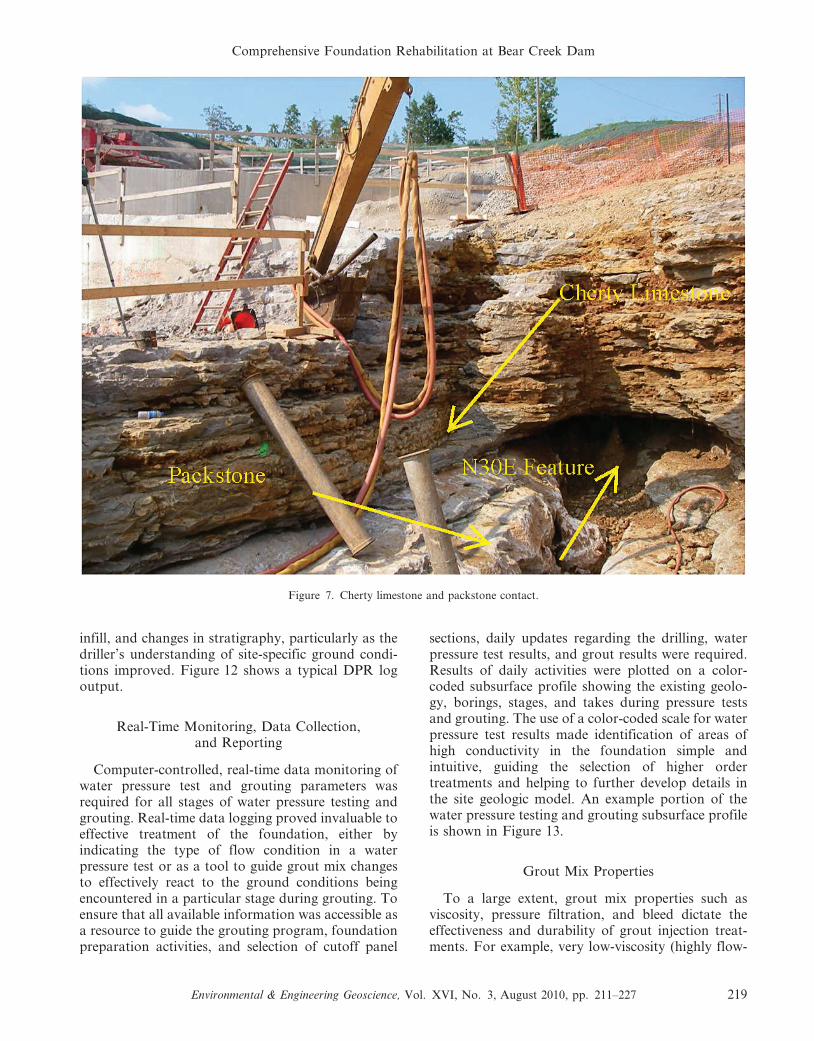
The configuration of the final rock surface wassignificantly controlled by stratigraphic and structuralcharacteristics. Specifically, in laboratory analyses, apackstone layer containing up to 21 percent (by wt.)SiO2 and up to 53 percent (by wt.) CaO, boundedabove and below by a cherty limestone containing 56percent (by wt.) SiO2, exhibited significant karstfeatures. Figures 5 and 6 show magnified views of thepackstone and overlying cherty limestone, respectively.Figure 7 shows the exposed contact of the packstoneand overlying cherty limestone. The blue arrows inFigure 5 point out the oolitic grains in the packstone.
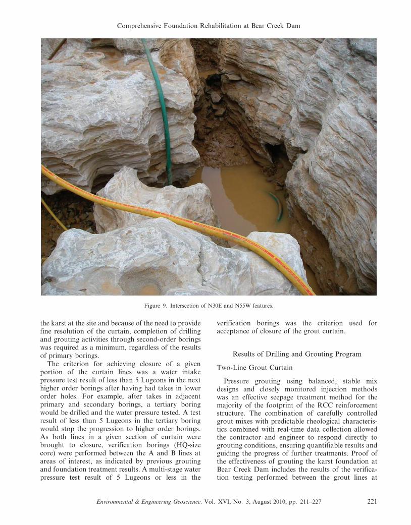
In addition, joints associated with bedding planesand two steeply dipping regional fracture sets strikingroughly N30E and N55W acted as zones of acceleratedweathering. Figures 8 and 9 show exposed N30Eweathered zones and the intersection of N30E andN55W features, respectively (note the 3 in.–diameteryellow hose for scale in Figure 9). Depending ondiscontinuity orientations, these features sometimesresulted in horizontal surfaces, vertical surfaces, bench-es, deep depressions, or overhangs. Generally, thefoundation surface was shaped adequately by conven-tional excavation using a track hoe and hoe ram. Over-excavation was appropriate in zones of weathered rockalong the aforementioned discontinuities.
Final Cleaning and Foundation Approval
The bedrock foundation for the RCC berm wascleaned under the guidance of the resident geologist
to provide acceptable conditions of contact betweenthe body of the dam and its foundation and toprovide for observation and documentation of detailsof foundation conditions at the foundation interface.Exposure of potentially adverse conditions duringcleanup provided the opportunity to undertakeremedial activity. The rock surface was cleaned sothat partially weathered to fresh rock was exposed fordental concrete placement.
After excavation, all loose or otherwise objection-able (weathered) material, detritus, and spoil wasremoved by handwork, water jetting, and/or airjetting. Accumulated water and debris from washingoperations were typically removed by a hydro-excavator or vacuum truck. Loose or unsuitablematerial in cavities, fractures, or seams was alsoremoved using the aforementioned techniques. Therock surface and all pockets or depressions werecarefully cleaned of soil and rock fragments beforedental concrete could be placed. Final foundationcleaning was achieved with the use of picks, shovels,pressure washers, and a vacuum truck.
Once cleaned, a RIZZO geologist mapped thefoundation at a scale of 1:120 or 1 in. to 10 ft in orderto describe the degree of weathering, hardness,lithology, and locating and describing discontinuities,in accordance with the USBR Engineering GeologyField Manual (U.S. Department of the Interior,1998). Once the area was mapped, photographed,and verified as a suitable foundation surface, thegeologist completed a foundation acceptance form for
Figure 3. Resistivity profile showing weathered zones in Bangor Shale Unit C beneath historic Bear Creek channel.
Comprehensive Foundation Rehabilitation at Bear Creek Dam
Environmental & Engineering Geoscience, Vol. XVI, No. 3, August 2010, pp. 211–227 215
the prepared area in order to track the approvalprocedure. Field data acquired in the geologicmapping process were then converted to AutoCadmaps to provide a final record of foundationconditions. Figure 10 provides an example plan viewfoundation geologic map showing the prominentN30E excavated zones.
The rock surface was thoroughly cleaned, asdescribed above, and moistened prior to concreteplacement to promote bonding between the concreteand the rock surface. Dental concrete was also used tofill or shape holes, grooves, and extensive areas ofvertical surfaces created by fractures, buried karstfeatures, and other irregularities. Thin areas of dentalconcrete over rock projections on a jagged rocksurface are likely places for crack propagation andwere avoided by providing short forms or trimmingfeather edges after curing. When overhangs werefilled with dental concrete, the concrete was wellvibrated and forced into the opening by keeping thehead of the concrete higher than the upper surface of
the overhang. Dental concrete was typically wetcured, and heavy equipment operations were notpermitted over the dental concrete until 48 hours ofcuring had been achieved.
Dental concrete was placed in approximately 1-ftlifts using a pump truck in order to preventsegregation during deep placements and over largeareas. Once dental concrete was placed in cleanedsolution features and crevasses, an as-built micro-topographic survey of the top of the concrete wascompleted in order to track the foundation treatmentprogress. Additional assessment of the foundationcleaning and the dental concrete placement wascompleted using confirmatory depth and positiondata from the grouting program, which followed thefoundation excavation and dental treatment process.Water pressure tests of core holes through thesegments of dental concrete that reached thicknessesas great as 18 ft and visual inspection of the corethrough the concrete rock interface yielded evidenceof no water takes and clean concrete-rock contacts.
Figure 4. Weathered zones mapped in Bangor Shale Unit C beneath historic Bear Creek channel.
Charlton, Ginther, and Bruce
216 Environmental & Engineering Geoscience, Vol. XVI, No. 3, August 2010, pp. 211–227
Water pressure tests were not performed in situationsin which there were fewer than 10 ft of dental concreteabove the top of the test interval.
Preparation of the foundation required excavationof approximately 40,000 cubic yards of residual soil,25,000 cubic yards of alluvium, 6,000 cubic yards offill, and 10,000 cubic yards of moderately to intenselyweathered rock. Approximately 100 cubic yards ofexisting detritus was removed from solution cavities.Five thousand five hundred cubic yards of minimum3,000-psi dental concrete was placed in irregularitiesin the foundation, and an additional 1,200 cubicyards was placed in order to prepare a more levelworking surface for drill rigs and to provide a surfaceconducive to RCC placement.
DRILLING AND GROUTING PROGRAM
Design and Implementation of Drilling andGrouting Program
The Bear Creek drilling and grouting program wasdesigned with the following three objectives:
N to effectively seal ‘‘groutable’’ (i.e., relatively cleanand open) fractures and voids in the dissolved andweathered rock mass under the foundation of theRCC reinforcement structure;
N as an exploration and design tool to determine thenecessary extents of the cutoff wall panels atlocations where ground conditions, such as clayinfill and intense weathering, would limit theeffectiveness of a grout-only barrier; and
N to act as a preliminary treatment to facilitate thepossible construction of cutoff panels.
In order to meet these objectives, the program wasdesigned using information from the initial subsurfaceexploration and foundation excavation and cleaningwork. The program was developed and operated toprovide the maximum amount of subsurface infor-mation possible in real time in order to increaseunderstanding of the foundation conditions, to createa treatment spacing with enough resolution to limitthe possibility of leaving untreated windows in theseepage barrier, and to provide grout mix propertiesthat would facilitate treatment of the foundation.
Figure 5. Packstone (scale is marked in millimeters).
Comprehensive Foundation Rehabilitation at Bear Creek Dam
Environmental & Engineering Geoscience, Vol. XVI, No. 3, August 2010, pp. 211–227 217
Subsurface Exploration
In order to further develop understanding of thefoundation conditions, a comprehensive system oflogging both exploratory (HQ size core) and produc-tion (rotary percussive drilling) borings, includingdownhole geophysical methods, was enacted for thedrilling and grouting program.
A total of 34 exploratory HQ-size core holes wereplaced on 80-ft centers on both lines of the groutcurtain. These borings were logged conventionally bya geologist in the field as the core was recovered andwere then subjected to geophysical logging after beingwashed thoroughly when the coring was completed.Geophysical logging included photographic loggingof the walls of the core hole with a downhole opticalteleviewer camera capable of identifying beddingfeatures and fractures and producing a 360u view ofboring sidewalls, gamma logging to assist in delineat-ing bedding features (primarily shale lenses), andcaliper logging to measure spatial deviations in thesidewalls of the core hole. The addition of thegeophysical logs to conventional logging practiceenhanced understanding of the subsurface fracturepatterns and solution mechanisms and proved very
valuable to the generation of an accurate portrait ofthe site stratigraphy. Figure 11 is a portion of a logproduced by the optical televiewer showing thecamera shot of a vertical fracture encountered in thecore hole within the cherty zone of the BangorLimestone and the corresponding mapping datarecorded by the televiewer.
Upon completion of coring and logging of theexploratory borings, the borings were water pressuretested using five-step Houlsby tests (Houlsby, 1990)and grouted as production grout borings, whennecessary.
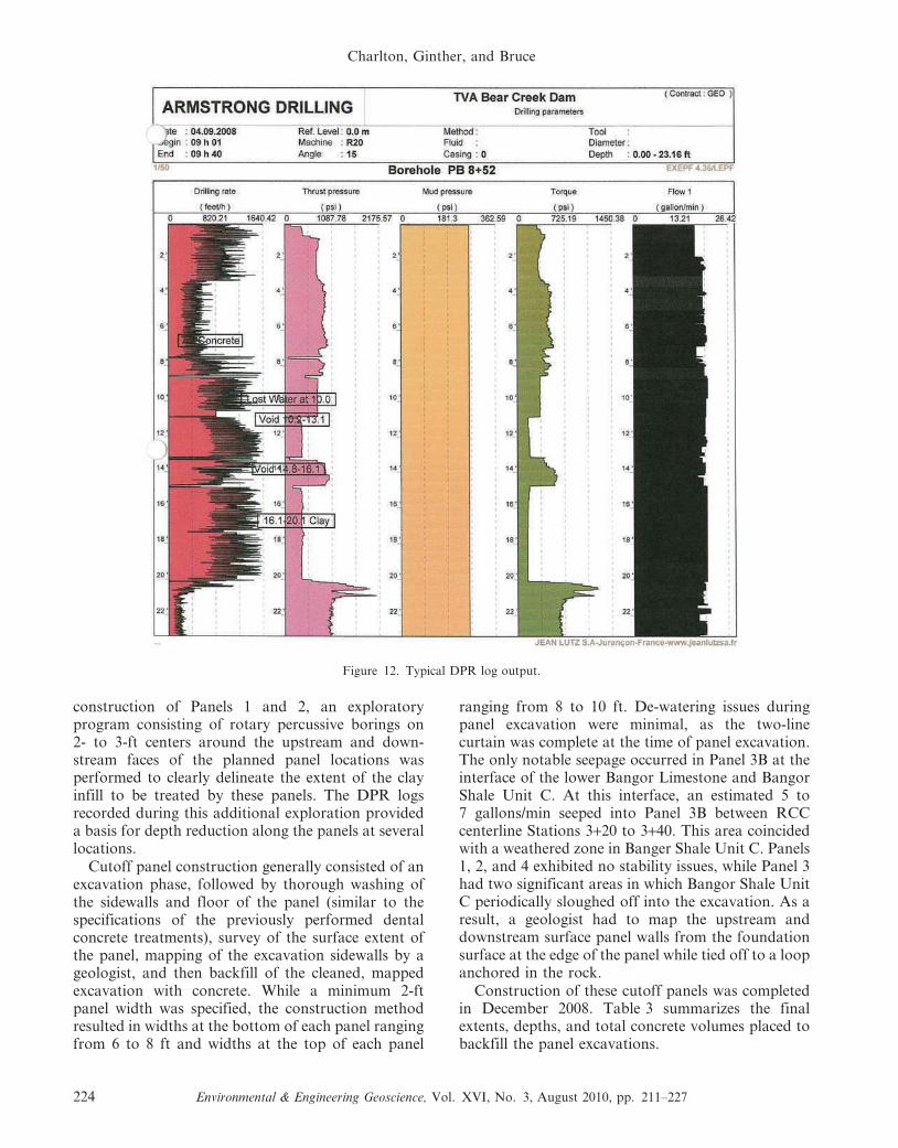
Upon completion of the exploratory borings in agiven area, production drilling (starting with primaryholes) was performed using a rotary percussive drillrig, with water used as the flushing medium. In orderto gain information from these destructive drillingtechniques, a Drilling Parameter Recorder (DPR) wasinstalled on the drill rig; this DPR recorded drillingrate, thrust pressure, drilling torque, and water flowthrough the drill string for every boring performed(Weaver and Bruce, 2007). Through the course of theproject, the DPR logs proved to be a valuableresource for identifying areas of fractured rock, clay
Figure 6. Cherty limestone (scale is marked in millimeters).
Charlton, Ginther, and Bruce
218 Environmental & Engineering Geoscience, Vol. XVI, No. 3, August 2010, pp. 211–227
infill, and changes in stratigraphy, particularly as thedriller’s understanding of site-specific ground condi-tions improved. Figure 12 shows a typical DPR logoutput.
Real-Time Monitoring, Data Collection,and Reporting
Computer-controlled, real-time data monitoring ofwater pressure test and grouting parameters wasrequired for all stages of water pressure testing andgrouting. Real-time data logging proved invaluable toeffective treatment of the foundation, either byindicating the type of flow condition in a waterpressure test or as a tool to guide grout mix changesto effectively react to the ground conditions beingencountered in a particular stage during grouting. Toensure that all available information was accessible asa resource to guide the grouting program, foundationpreparation activities, and selection of cutoff panel
sections, daily updates regarding the drilling, waterpressure test results, and grout results were required.Results of daily activities were plotted on a color-coded subsurface profile showing the existing geolo-gy, borings, stages, and takes during pressure testsand grouting. The use of a color-coded scale for waterpressure test results made identification of areas ofhigh conductivity in the foundation simple andintuitive, guiding the selection of higher ordertreatments and helping to further develop details inthe site geologic model. An example portion of thewater pressure testing and grouting subsurface profileis shown in Figure 13.
Grout Mix Properties
To a large extent, grout mix properties such asviscosity, pressure filtration, and bleed dictate theeffectiveness and durability of grout injection treat-ments. For example, very low-viscosity (highly flow-
Figure 7. Cherty limestone and packstone contact.
Comprehensive Foundation Rehabilitation at Bear Creek Dam
Environmental & Engineering Geoscience, Vol. XVI, No. 3, August 2010, pp. 211–227 219
able) grouts are suitable for treatment of relativelyfine fractures, while higher viscosity grouts aretypically necessary to effectively seal more openfractures. In cases of large voids and/or flowinggroundwater, low-mobility grout (LMG) may berequired to arrest flow and fill the void.
As a result of the extreme variability of thesubsurface conditions at Bear Creek Dam, weemployed both high-mobility grout (HMG) forrelatively small, open features and fractures andLMG for large voids and subsurface flows that causewashout of HMG. A suite of three balanced, stableHMG mixes with the properties shown in Table 1 wasrequired in the design phase.
In addition to the required suite of mixes, thecontractor performing the drilling and groutingprogram elected to add a ‘‘medium-mobility grout’’mix to the suite, consisting of Mix C batched with flyash. This mix proved very useful in bringing large takeholes to closure through the course of the project.
Because of the particular nature of LMG injection,a mix and method were not directly specified; rather,it was left to the discretion of the contractor topropose a method according to his proprietaryequipment and experience.
Grout Curtain Resolution and Closure
In order to provide a continuous seepage barrierand to clearly characterize the subsurface under the
foundation of the RCC berm, the two-line groutcurtain extends from the area downstream of the leftabutment of the existing embankment across theexisting spillway structure, and it terminates at theright abutment of the RCC berm to the north.Figure 14 shows the layout of the drilling andgrouting program.
To provide a tight-enough treatment spacing tolimit the possibility of leaving untested or untreatedwindows in the foundation, two grout lines (located10 ft apart) of opposing holes inclined 15u fromvertical were planned. The ‘‘A’’ line parallels the RCCcenterline to the upstream, while the ‘‘B’’ line parallelsthe RCC centerline to the downstream. Primary andsecondary borings on each line were set at 20-ftcenter-to-center spacing, with tertiaries and higherorder borings split spaced, as indicated by the resultsof lower order holes. To provide a clear means ofidentifying the order of performance and location ofborings, a system employing the boring order, groutline, and RCC stationing at the location wasdeveloped, as shown below: For a primary boringon the ‘‘A’’ line at RCC Station 4+50, the boring labelis PB 4+50. Figure 15 shows the typical grout holelayout.
Primary borings were extended into the BangorShale layer, while the depths of higher order boringswere generally selected based on available informa-tion, such as stratigraphy and previous water pressuretest results. In light of the highly variable nature of
Figure 8. Cleaning of N30E features.
Charlton, Ginther, and Bruce
220 Environmental & Engineering Geoscience, Vol. XVI, No. 3, August 2010, pp. 211–227
the karst at the site and because of the need to providefine resolution of the curtain, completion of drillingand grouting activities through second-order boringswas required as a minimum, regardless of the resultsof primary borings.
The criterion for achieving closure of a givenportion of the curtain lines was a water intakepressure test result of less than 5 Lugeons in the nexthigher order borings after having had takes in lowerorder holes. For example, after takes in adjacentprimary and secondary borings, a tertiary boringwould be drilled and the water pressure tested. A testresult of less than 5 Lugeons in the tertiary boringwould stop the progression to higher order borings.As both lines in a given section of curtain werebrought to closure, verification borings (HQ-sizecore) were performed between the A and B lines atareas of interest, as indicated by previous groutingand foundation treatment results. A multi-stage waterpressure test result of 5 Lugeons or less in the
verification borings was the criterion used foracceptance of closure of the grout curtain.
Results of Drilling and Grouting Program
Two-Line Grout Curtain
Pressure grouting using balanced, stable mixdesigns and closely monitored injection methodswas an effective seepage treatment method for themajority of the footprint of the RCC reinforcementstructure. The combination of carefully controlledgrout mixes with predictable rheological characteris-tics combined with real-time data collection allowedthe contractor and engineer to respond directly togrouting conditions, ensuring quantifiable results andguiding the progress of further treatments. Proof ofthe effectiveness of grouting the karst foundation atBear Creek Dam includes the results of the verifica-tion testing performed between the grout lines at
Figure 9. Intersection of N30E and N55W features.
Comprehensive Foundation Rehabilitation at Bear Creek Dam
Environmental & Engineering Geoscience, Vol. XVI, No. 3, August 2010, pp. 211–227 221
locations of high pre-treatment permeability, visualobservations of reduced downstream flows into thespillway tailrace, and post-treatment excavationsperformed in–the–dry within the foundation. Oneexample of a visual expression of the grout curtain’seffectiveness is discussed below.
Indications for Cutoff Wall Panels
At several locations, ground conditions preventedthe grouting program from providing a robustseepage barrier that would be effective in the longterm. These ‘‘ungroutable’’ conditions correspond tosignificant subsurface clay infill encountered at twolocations near the left abutment and to the existenceof very weathered zones in the Bangor Shale geologicunit in the old river channel.
Clay infill conditions were encountered in thedrilling and grouting program between RCC stations7+00 to 7+40 and 8+00 to 8+67 from depths asshallow as 5 ft up to depths of 25 ft. Clay infillconditions at these locations were determined to becaused by intersecting solution features or cavesconcealed by very hard cherty caprock, as opposedto the larger solution features, which had surfaceexpression. These connecting caves were full of clayand detritus to varying degrees, with some large voids
with significant underflows encountered. Those loca-tions in which voids with significant seepage wereencountered required the injection of approximately50 cubic yards of LMG to arrest the seepage flows.
In the area of the old river channel, much lesslimestone cover exists over the underlying BangorShale. As a result of being less protected fromweathering, the shale layer, which at other locationson the site acts as a near-continuous water barrier,was found to have several intensely weathered zonesthrough it. Where slightly weathered, the shaletypically would demonstrate hydraulic conductivityin water pressure testing that ranged from 0 to 10Lugeons, and this shale would exhibit very low grouttakes. Where intensely weathered, grout takes werehigh, and grouting operations often resulted in groutconnections to other borings and the rock surface inthe surrounding area.
Geologic conditions encountered in the foundationpreparation and drilling and grouting programindicated the need for a total of four cutoff panelsat depths ranging from 23 to 35 ft. Careful collectionand review of field data by the Team (TVA, IRB, andRIZZO) made possible the very directed treatment ofnon-groutable zones and minimization of cutoff panelcosts. The following section summarizes the finaldesign and installation of the cutoff panels.
Figure 10. Geologic map of foundation.
Charlton, Ginther, and Bruce
222 Environmental & Engineering Geoscience, Vol. XVI, No. 3, August 2010, pp. 211–227
CUTOFF PANEL INSTALLATION PROGRAM
Cutoff Panel Design and ConstructionMethod Selection
In all, four cutoff wall panels were prescribed inlight of the results of the drilling and groutingprogram and a supplemental exploratory drillingprogram consisting of rotary percussive borings on2- or 3-ft centers. DPR drilling logs from thesupplemental drilling were used to clearly identifythe vertical and lateral extents of clay infill for Panels1 and 2. The panels, their limits, and the reasons forwhich the panels were necessary are outlined inTable 2.
Cutoff panels were centered between the A and Blines of the drilling and grouting program in order tomake best use of the pre-treatment afforded by thepreviously performed grouting. Several constructionmethods were evaluated for the construction of thesecutoff panels, including drilling and blasting prior toexcavation, use of a secant pile wall system, and theuse of an excavator-mounted hoe-ram and long-reachexcavator to remove the material from the cutoff wallsections. Drilling and blasting was eventually dis-counted as a viable construction method as a result ofconcerns over damage to the thinly bedded overlying
limestone and because of concerns about the effec-tiveness of blasting in the shale unit. Secant pileinstallation was the technically preferred method ofinstallation of the cutoff panels, as it was method thatwas least likely to cause damage to the foundationand previous grout treatments and because it offeredrelative ease of installation at depth and relatively lowvolume of excavation to be backfilled. However, thehigh cost of mobilization of a secant pile contractor,in relation to the small area treatment, in addition toschedule availability issues prevented the use of asecant pile contractor. In the end, the constructionmethod utilizing excavation with a hoe-ram and long-reach excavator was selected because of the availabil-ity of the necessary equipment within TVA’s HeavyEquipment Division.
Cutoff Panel Construction Details
Construction of the cutoff panels began with Panel4, which served as a proof-of-method test. Panel 4was chosen to test the hoe-ram and excavationconstruction method because of its smaller size andshallower depth. Based on successful performance inthe installation of Panel 4, the method was approvedfor the remaining sections of cutoff wall. Prior to
Figure 11. Section of optical televiewer log showing mapped fracture. Depth in feet.
Comprehensive Foundation Rehabilitation at Bear Creek Dam
Environmental & Engineering Geoscience, Vol. XVI, No. 3, August 2010, pp. 211–227 223
construction of Panels 1 and 2, an exploratoryprogram consisting of rotary percussive borings on2- to 3-ft centers around the upstream and down-stream faces of the planned panel locations wasperformed to clearly delineate the extent of the clayinfill to be treated by these panels. The DPR logsrecorded during this additional exploration provideda basis for depth reduction along the panels at severallocations.
Cutoff panel construction generally consisted of anexcavation phase, followed by thorough washing ofthe sidewalls and floor of the panel (similar to thespecifications of the previously performed dentalconcrete treatments), survey of the surface extent ofthe panel, mapping of the excavation sidewalls by ageologist, and then backfill of the cleaned, mappedexcavation with concrete. While a minimum 2-ftpanel width was specified, the construction methodresulted in widths at the bottom of each panel rangingfrom 6 to 8 ft and widths at the top of each panel
ranging from 8 to 10 ft. De-watering issues duringpanel excavation were minimal, as the two-linecurtain was complete at the time of panel excavation.The only notable seepage occurred in Panel 3B at theinterface of the lower Bangor Limestone and BangorShale Unit C. At this interface, an estimated 5 to7 gallons/min seeped into Panel 3B between RCCcenterline Stations 3+20 to 3+40. This area coincidedwith a weathered zone in Banger Shale Unit C. Panels1, 2, and 4 exhibited no stability issues, while Panel 3had two significant areas in which Bangor Shale UnitC periodically sloughed off into the excavation. As aresult, a geologist had to map the upstream anddownstream surface panel walls from the foundationsurface at the edge of the panel while tied off to a loopanchored in the rock.
Construction of these cutoff panels was completedin December 2008. Table 3 summarizes the finalextents, depths, and total concrete volumes placed tobackfill the panel excavations.
Figure 12. Typical DPR log output.
Charlton, Ginther, and Bruce
224 Environmental & Engineering Geoscience, Vol. XVI, No. 3, August 2010, pp. 211–227
Results of Cutoff Panel Construction Program
After several days of set time, verification coreborings were drilled along the centerline of each panelat 20–30-ft spacing, and five-step, Houlsby-type waterpressure was tested to verify the integrity of the panel.Boring locations were chosen to intercept theabutments of the panels, the bottom contact of thepanel with the foundation, or in some cases areas ofinterest or concern based on foundation conditionsnoted during the mapping process. The acceptancecriterion for the cutoff panels was 5 Lugeons, thesame as for the two-line grout curtain. In fact, allverification tests performed through the cutoff panelsyielded ‘‘no take’’ (0 Lugeon) results. After comple-
tion of the water pressure testing and acceptance ofthe panel, verification boreholes were backfilled witha high-strength cement.
CONCLUSION
TVA’s Bear Creek Dam is a high-hazard potentialembankment dam with a history of potentiallyhazardous seepage flows developed or exacerbatedduring its service history through the karst limestonefoundation of the dam. In addition, the dam had apotential danger of failure as a result of PMFovertopping. Historically, limited success at reducingseepage flows was achieved with additional remedial
Figure 13. Example subsurface profile. Width of profile is 35 feet.
Table 1. High-mobility grout properties.
Parameter (unit) Mix A Mix B Mix C Purpose of Requirement
Kpf (minutes21/2)#.040 #.040 #.040 Low pressure filtration corresponds to less mix water being
pressed out of the grout, promotes long-distance penetrationinto fractures
Marsh viscosity (seconds) 35 50–55 80+ Provide range of viscosities to adjust, as appropriate to subsurfaceconditions
Initial stiffening time (hours) $3 $3 $3 Provide enough time for mix, injection, and travel prior toinitial set
Comprehensive Foundation Rehabilitation at Bear Creek Dam
Environmental & Engineering Geoscience, Vol. XVI, No. 3, August 2010, pp. 211–227 225
Figure 14. Drilling and grouting program layout.
Figure 15. Typical grout hole layout.
Table 2. Cutoff panel information.
Cutoff Panel No. Station Extents Expected Maximum Depth (ft) Geologic Rationale for Panel
Panel 1 8+00 to 8+67 35 Clay infill/void activity at depths of 25–30 ftPanel 2 7+00 to 7+40 35 Clay infill at depths of up to 30 ftPanel 3 3+10 to 4+77 35 Cutoff very weathered zones in the Bangor Shale at the
maximum section of the new structurePanel 4 2+40 to 2+50 23 Cutoff the continuation of N32E sluiceway solution
feature, act as test panel for construction method
Table 3. Cutoff panel construction details.
Cutoff Panel No. Station ExtentsAs-Built Maximum
Depth (ft)Cutoff Panel
Area (SF)Concrete Volume
Placed (CY)
Panel 1 8+00 to 8+67 32 2,013 594Panel 2 7+00 to 7+40 22 754 276Panel 3 3+10 to 4+77 32 5,490 1,416Panel 4 2+40 to 2+50 23 250 100
Charlton, Ginther, and Bruce
226 Environmental & Engineering Geoscience, Vol. XVI, No. 3, August 2010, pp. 211–227
grout treatments; however, these reductions havebeen lost over time. In order to provide a robust,long-term seepage barrier, a comprehensive treatmentprogram was designed to provide effective control ofsubsurface flows in the difficult karst terrain; thisprogram consisted of an extensive foundation clean-ing and dental treatment program; use of a two-linegrout curtain using balanced, stable mix designs andreal-time computer monitoring; and a cutoff panelinstallation program at locations indicated by theprevious treatments. Additionally, an RCC reinforce-ment structure downstream of the existing embank-ment has been completed.
Successful rehabilitation of the karst foundation atBear Creek Dam was achieved by implementing aprogressive series of construction measures to fullytreat the complicated geology. To effectively tailor theindividual aspects of the foundation rehabilitation, itwas critical to continuously update the understandingof the site geologic setting as more data were procuredin successive treatments. To that end, real-time datacollection and processing in conjunction with daily
reporting of relevant conditions and maintenance ofan evolving concept of the site-specific karst system inCAD models enabled the team to effectively andsuccessfully manage the treatment program.
DISCLAIMER
It should be noted that in allowing publication ofthis article, the TVA does not endorse any entity orfirm associated with this work.
REFERENCES
HOULSBY, A. C., 1990, Construction and Design of Cement
Grouting: John Wiley and Sons, New York, 442 p.
U.S. DEPARTMENT OF THE INTERIOR, BUREAU OF RECLAMATION,1998, Engineering Geology Field Manual, 2nd ed., Vol. 1:Denver, Colorado.
WEAVER, K. D. AND BRUCE, D. A., 2007, Dam Foundation
Grouting, revised and expanded edition: American Societyof Civil Engineers, ASCE Press, Reston, VA, 473 p.
Comprehensive Foundation Rehabilitation at Bear Creek Dam
Environmental & Engineering Geoscience, Vol. XVI, No. 3, August 2010, pp. 211–227 227