16
CONNECTED TO INNOVATION COMPRESSED AIR NETWORKS, AMPS CONCEPT

connected to innovation
coMPReSSed aiR netWoRKS,
AMPS concePt

The AMPS range
AMPS is a simple and reliable aluminium profile connection system for the installation of compressed air distribution networks.
AMPS uses a specific aluminium profile whose geometry has been developed to ensure the distribution of compressed air. it is a unique and innovative system.
approved and certified by the German certification organisation, tÜv, AMPS offers the assurance of a reliable and approved system.
assembly and installation is performed without the need for preparation or specific tools. the profile is cut to the desired length and directly assembled with the appropriate couplings. Multiple combinations are possible and extensively modifiable. the AMPS range brings optimal solutions for the installation of compressed air networks.
thanks to an aW6063 - t66 aluminium construction, the piping profiles are light and clean. the perfectly smooth internal surface ensures optimum flow.
assemblies are realised with:
• Tube couplings equipped with a dual O-ring seal, ensuring perfect sealing.
• Connection plates that ensure that assemblies are secured together using grooves in the profile
• Accessories: Straight couplings, angled couplings, reducers, stoppers, orientable swivel couplings, three way couplings, five way couplings, connection plates, wall or ceiling brackets.
the assembly components are perfectly suited and allow the assembly of robust, reliable and well-finished installations, whether for large industrial facilities, small installations or workstation equipment.
General characteristics
Tube internal diameter: Ø 25 mm, 38 mm, 50 mm, 75 mm and 100 mm
Technical specifications: Profiles and couplings: aW6063 - t66 aluminium
coupling seals: nBR 70 rubber
Service pressure: -0.99 - 15 bar
temperature range: -40° c to +100° c
Fluids: compressed air.
2 aMPS network
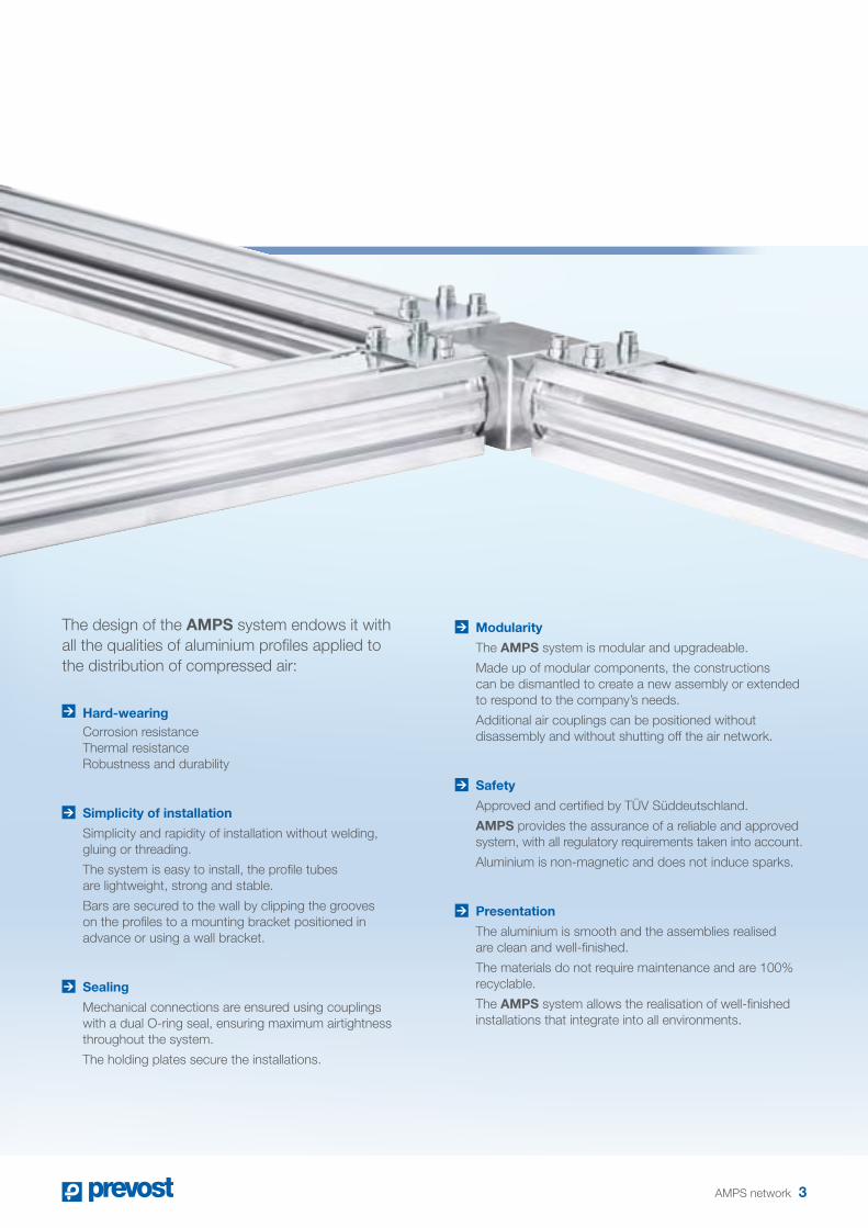
the design of the AMPS system endows it with all the qualities of aluminium profiles applied to the distribution of compressed air:
Hard-wearing corrosion resistance thermal resistance Robustness and durability
Simplicity of installation
Simplicity and rapidity of installation without welding, gluing or threading.
the system is easy to install, the profile tubes are lightweight, strong and stable.
Bars are secured to the wall by clipping the grooves on the profiles to a mounting bracket positioned in advance or using a wall bracket.
Sealing
Mechanical connections are ensured using couplings with a dual o-ring seal, ensuring maximum airtightness throughout the system.
the holding plates secure the installations.
Modularity
the AMPS system is modular and upgradeable.
Made up of modular components, the constructions can be dismantled to create a new assembly or extended to respond to the company’s needs.
additional air couplings can be positioned without disassembly and without shutting off the air network.
Safety
approved and certified by tÜv Süddeutschland.
AMPS provides the assurance of a reliable and approved system, with all regulatory requirements taken into account.
aluminium is non-magnetic and does not induce sparks.
Presentation
the aluminium is smooth and the assemblies realised are clean and well-finished.
the materials do not require maintenance and are 100% recyclable.
the AMPS system allows the realisation of well-finished installations that integrate into all environments.
aMPS network 3

AMPS network in aluminium profiles
*Value under pressure of 8 bar with a pressure loss of 0,1 bar (the pressure drop due to couplings is equivalent to 1,5 m of pipe for each coupling used).
Flow rate Bar inner diameter as a function of network length*
l/min m3/h cfm98.4 ft 164 ft 328 ft 656 ft 1312 ft 1640 ft 2624 ft 3608 ft 4920 ft
30 m 50 m 100 m 200 m 400 m 500 m 800 m 1100 m 1500 m
500 30 295 25 25 25 25 25 25 25 25 25750 45 442 25 25 25 25 25 25 25 25 38
1500 90 884 25 25 25 25 38 38 38 38 38
3000 180 1767 25 25 38 38 38 38 50 50 50
5000 300 2946 25 25 38 38 50 50 50 50 75
7000 420 4124 38 38 50 50 50 50 75 75 75
9000 540 5302 38 38 50 50 50 75 75 75 75
11000 660 6481 38 38 50 50 75 75 75 75 75
13000 780 7659 38 38 50 50 75 75 75 75 75
15000 900 8837 38 50 50 75 75 75 75 75 100
17000 1020 10015 38 50 50 75 75 75 75 100 100
19000 1140 11194 50 50 50 75 75 75 100 100 100
21000 1260 12372 50 50 50 75 75 75 100 100 100
23000 1380 13550 50 50 75 75 75 75 100 100 100
25000 1500 14279 50 50 75 75 75 100 100 100 100
27000 1620 15907 50 50 75 75 100 100 100 100 100
Tubes in AMPS PRO profilesthe extruded aluminium bars are the heart of the system. they are light, stable and the interior surface of the tube is perfectly smooth.Bar length: 6 metres.tube internal diameters: 25 mm, 38 mm, 50 mm, 75 mm or 100 mm.the grooves on the profiles are used for assembling, securing and mounting the system. they also allow all types of mounts with the use of the foreseen screw/nut kits.
4 aMPS network

Assembly parts
AMPS LK Connection kit Linear assembly of two bars.assembly to be installed with a straight tube coupling and coupling flange appropriate for profile dimensions.
Ø (mm) connection flanges25 - 38 250 475 - 100 2
AMPS L Elbowassembly of two perpendicular bars to be secured using holding plates (aMPS HP).
AMPS LP Elbow with stopper Machined elbow with a third outlet closed with a male stopper. assembly of two perpendicular bars to be secured using holding plates (aMPS HP).if needed, a third bar can be added by removing the stopper.
AMPS T Tee-couplingassembly of three bars to be secured using holding plates (aMPS HP).
AMPS B Five way coupling to be equipped with straight male couplings Supplied without couplings, the five-way coupling provides the possibility of a choice of assemblies using straight male couplings (aMPS MS) and male stoppers (aMPS P).
Straight couplings
AMPS MS straight threaded male coupling for tube connecting piece allowing the installation of a tube on a male threaded outlet.tube to be secured using holding plates (aMPS HP).
AMPS FS straight female threaded coupling for tube connecting piece allowing the installation of a tube on a female threaded outlet.tube to be secured using holding plates (aMPS HP).
aMPS network 5
Assembly parts
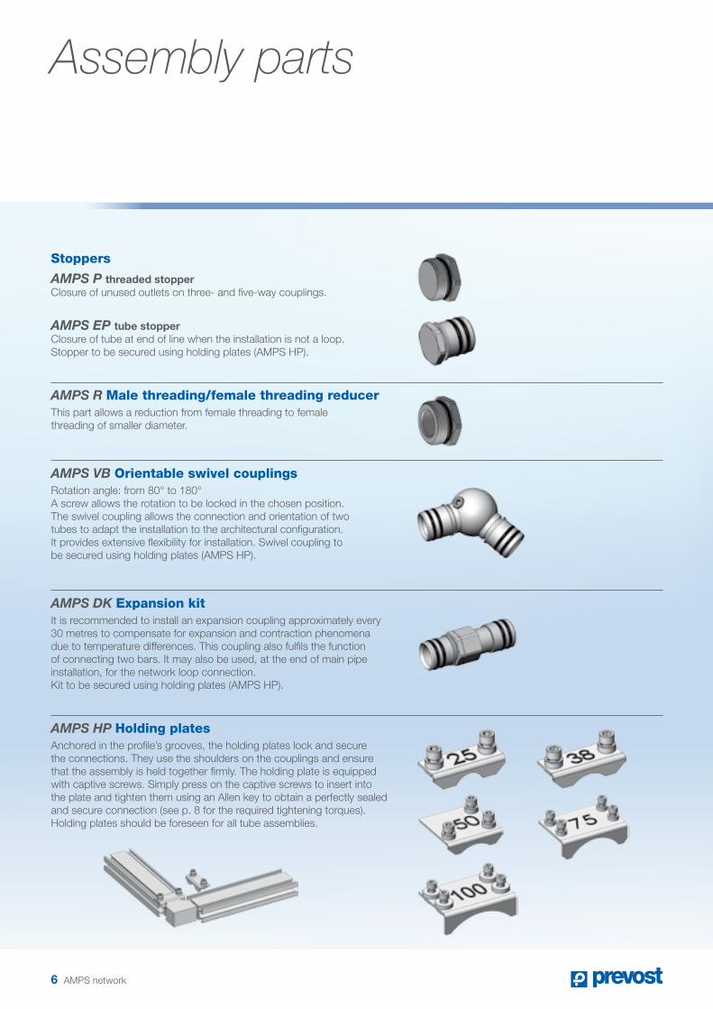
Stoppers
AMPS P threaded stopper closure of unused outlets on three- and five-way couplings.
AMPS EP tube stopper closure of tube at end of line when the installation is not a loop. Stopper to be secured using holding plates (aMPS HP).
AMPS R Male threading/female threading reducerthis part allows a reduction from female threading to female threading of smaller diameter.
AMPS VB Orientable swivel couplingsRotation angle: from 80° to 180°a screw allows the rotation to be locked in the chosen position.the swivel coupling allows the connection and orientation of two tubes to adapt the installation to the architectural configuration. it provides extensive flexibility for installation. Swivel coupling to be secured using holding plates (aMPS HP).
AMPS DK Expansion kitit is recommended to install an expansion coupling approximately every 30 metres to compensate for expansion and contraction phenomena due to temperature differences. this coupling also fulfils the function of connecting two bars. it may also be used, at the end of main pipe installation, for the network loop connection. Kit to be secured using holding plates (aMPS HP).
AMPS HP Holding platesanchored in the profile’s grooves, the holding plates lock and secure the connections. they use the shoulders on the couplings and ensure that the assembly is held together firmly. the holding plate is equipped with captive screws. Simply press on the captive screws to insert into the plate and tighten them using an allen key to obtain a perfectly sealed and secure connection (see p. 8 for the required tightening torques).Holding plates should be foreseen for all tube assemblies.
6 aMPS network

AMPS CP Connection plates Four models of plate are available.the choice of model depends on the profile used and the desired coupling size (from G 1/8 to G 2).the plates are mounted using both grooves on the profile: one to guide the plate when the tab is inserted in the groove, the other to attach the plate, using the quick screw/nut locking system.
AMPS D Drilling toola specific tool, ref. aMPS d38, aMPS d12, aMPS d34 (see p. 15), allows the drilling of holes in the profiles necessary for air tappings, whilst evacuating cuttings from the drilling operation. this drilling may be performed with the system pressurised, without the need to shut down compressed air delivery (see p. 9).
Network anchoring three types of anchoring, selected depending on workshop configuration.
AMPS WB wall bracket with clips
the securing of profiles to the wall or ceiling is achieved using brackets every 3 metres. there are two types of clip brackets, spaced 20 mm or 50 mm from the wall.the securing bracket is equipped with two clips and a strap that allow firm anchoring of the profile using its grooves. the bracket is first anchored to the wall after which the bar can simply be clipped on to be securely held.
AMPS WB60 bracket
the bracket is equipped with a captive screw. the bracket is held by the screw and nut secured in the profile’s groove.the aMPS W bracket can be used as a wall mount or to lock the rotation of two perpendicular bars.
Anchoring to ceiling using the AMPS WB80 threaded rod
a plate, female-threaded in its centre, is on one side secured in the profile’s grooves and on the other side equipped with a threaded rod. the threaded rod ensures anchoring to the ceiling and the suspension of the profile (not supplied).
aMPS network 7
Assembly principles
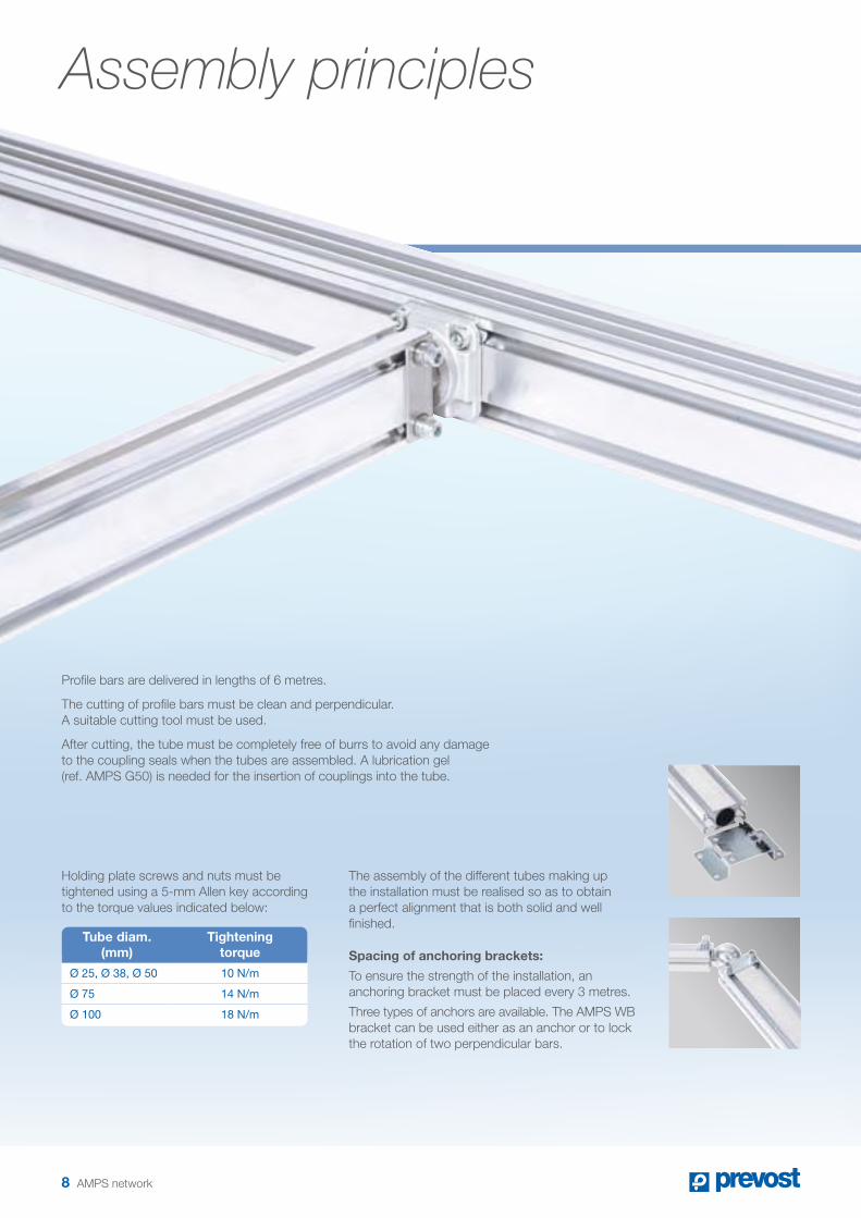
Holding plate screws and nuts must be tightened using a 5-mm allen key according to the torque values indicated below:
Tube diam. (mm)
Tightening torque
Ø 25, Ø 38, Ø 50 10 N/m
Ø 75 14 N/m
Ø 100 18 N/m
the assembly of the different tubes making up the installation must be realised so as to obtain a perfect alignment that is both solid and well finished.
Spacing of anchoring brackets:
to ensure the strength of the installation, an anchoring bracket must be placed every 3 metres.
three types of anchors are available. the aMPS WB bracket can be used either as an anchor or to lock the rotation of two perpendicular bars.
Profile bars are delivered in lengths of 6 metres.
the cutting of profile bars must be clean and perpendicular. a suitable cutting tool must be used.
after cutting, the tube must be completely free of burrs to avoid any damage to the coupling seals when the tubes are assembled. a lubrication gel (ref. aMPS G50) is needed for the insertion of couplings into the tube.
8 aMPS network
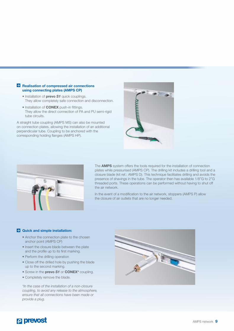
Realisation of compressed air connections using connecting plates (AMPS CP)
• Installation of prevo S1 quick couplings. they allow completely safe connection and disconnection.
• Installation of CONEX push-in fittings. they allow the direct connection of Pa and PU semi-rigid tube circuits.
a straight tube coupling (aMPS MS) can also be mounted on connection plates, allowing the installation of an additional perpendicular tube. coupling to be anchored with the corresponding holding flanges (aMPS HP).
Quick and simple installation:
• Anchor the connection plate to the chosen anchor point (aMPS cP)
• Insert the closure blade between the plate and the profile up to its first marking.
• Perform the drilling operation
• Close off the drilled hole by pushing the blade up to the second marking.
• Screw in the prevo S1 or CONEX* coupling.
• Completely remove the blade.
*In the case of the installation of a non-closure coupling, to avoid any release to the atmosphere, ensure that all connections have been made or provide a plug.
the AMPS system offers the tools required for the installation of connection plates while pressurised (aMPS cP). the drilling kit includes a drilling tool and a closure blade (kit ref.: aMPS d). this technique facilitates drilling and avoids the presence of shavings in the tube. the operator then has available 1/8”G to 2”G threaded ports. these operations can be performed without having to shut off the air network.
in the event of a modification to the air network, stoppers (aMPS P) allow the closure of air outlets that are no longer needed.
aMPS network 9

Wall fasteners
• Air inlet: G ½ or G ¾
• Material: Aluminium alloy
• 4-point wall mounting
• Incorporates pre-assembled, sealed manual drain
• Connection to AMPS tubing via aMPS MS straight male threaded coupling. the mount’s hole spacing with respect to the wall corresponds to the 20-mm spacing of the aMPS WB20 wall anchor with clips.
• Air outlet: 2 one-push safety couplings prevo S1
Network equipment
the installation of descending tubing (secondary vertical tubes) is achieved using the tee-coupling (aMPS t) or the five-way coupling equipped with straight male couplings (aMPS MS) and stoppers (aMPS P) for unused outlets.
the orientable swivel coupling (aMPS vB) installed between two sections of tubes allows the orientation of the tubing as a function of needs.
the installation of specific equipment is realised, at the end of the line, using straight male (aMPS MS) or female (aMPS FS) couplings and on horizontal tubing using connection plates (aMPS cP).
Placed on a secondary pipe, the prevo S1 wall fastener offers quick coupling for two connections. prevo S1 anti-hose whip couplings are compliant with the iSo 4414 standard ensuring the protection of the user.
Orientable body allowing the button position to be chosen
Rapid and easy connection and disconnection ensuring highly versatile operation
10 aMPS network
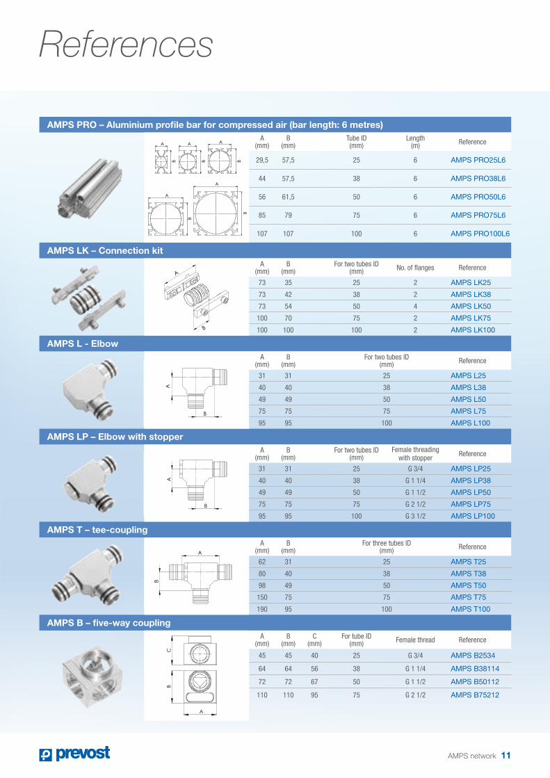
References
AMPS PRO – Aluminium profile bar for compressed air (bar length: 6 metres)A
(mm)B
(mm)Tube ID (mm)
Length (m) Reference
29,5 57,5 25 6 AMPS PRO25L6
44 57,5 38 6 AMPS PRO38L6
56 61,5 50 6 AMPS PRO50L6
85 79 75 6 AMPS PRO75L6
107 107 100 6 AMPS PRO100L6
AMPS LK – Connection kitA
(mm)B
(mm)For two tubes ID
(mm) No. of flanges Reference
73 35 25 2 AMPS LK25
73 42 38 2 AMPS LK38
73 54 50 4 AMPS LK50
100 70 75 2 AMPS LK75
100 100 100 2 AMPS LK100
AMPS L - ElbowA
(mm)B
(mm)For two tubes ID
(mm) Reference
31 31 25 AMPS L25
40 40 38 AMPS L38
49 49 50 AMPS L50
75 75 75 AMPS L75
95 95 100 AMPS L100
AMPS LP – Elbow with stopperA
(mm)B
(mm)For two tubes ID
(mm)Female threading
with stopper Reference
31 31 25 G 3/4 AMPS LP25
40 40 38 G 1 1/4 AMPS LP38
49 49 50 G 1 1/2 AMPS LP50
75 75 75 G 2 1/2 AMPS LP75
95 95 100 G 3 1/2 AMPS LP100
AMPS T – tee-couplingA
(mm)B
(mm)For three tubes ID
(mm) Reference
62 31 25 AMPS T25
80 40 38 AMPS T38
98 49 50 AMPS T50
150 75 75 AMPS T75
190 95 100 AMPS T100
AMPS B – five-way couplingA
(mm)B
(mm)C
(mm)For tube ID
(mm) Female thread Reference
45 45 40 25 G 3/4 AMPS B2534
64 64 56 38 G 1 1/4 AMPS B38114
72 72 67 50 G 1 1/2 AMPS B50112
110 110 95 75 G 2 1/2 AMPS B75212
B
A
B
A
A
B
CB
A
A A A A A
B B B B B
A
B
A
B
A
B
A
B
A
B
A A A A A
B B B B B
A
B
A
B
A
B
A
B
A
B
aMPS network 11
A
B

12 aMPS network
References
AMPS P – Straight male couplingA
(mm)C
(mm)For tube ID
(mm) Male threading Reference
40 27 25 G 1/2 AMPS MS2512
40 27 25 G 3/4 AMPS MS2534
50 44 38 G 1 1/4 AMPS MS38114
60 55 50 G 1 1/2 AMPS MS50112
88 80 75 G 2 1/2 AMPS MS75212
88 106 100 G 3 AMPS MS1003
88 106 100 G 3 1/2 AMPS MS100312
AMPS FS – Straight female couplingA
(mm)C
(mm)For tube ID
(mm) Female thread Reference
30 27 25 G 3/8 AMPS FS2538
30 27 25 G 1/2 AMPS FS2512
32 44 38 G 1/2 AMPS FS3812
32 44 38 G 3/4 AMPS FS3834
48 55 50 G 1/2 AMPS FS5012
48 55 50 G 3/4 AMPS FS5034
48 55 50 G 1 AMPS FS501
70 80 75 G 1 1/2 AMPS FS75112
70 80 75 G 2 1/2 AMPS FS75212
97 106 100 G 2 1/2 AMPS FS100212
97 106 100 G 3 AMPS FS1003
AMPS P – Male stopperA
(mm)C
(mm) Male threading Reference
15 27 G 3/4 AMPS P2534
20 44 G 1 1/4 AMPS P38114
20 55 G 1 1/2 AMPS P50112
28 80 G 2 1/2 AMPS P75212
33 106 G 3 1/2 AMPS P100312
AMPS EP – End stopperA
(mm)C
(mm)For tube ID
(mm) Reference
30 27 25 AMPS EP25
32 44 38 AMPS EP38
48 55 50 AMPS EP50
70 80 75 AMPS EP75
97 106 100 AMPS EP100
AMPS R – Male/female reducerA
(mm)C
(mm) Male threading Female thread Reference
15 44 G 1 1/4 G 3/4 AMPS R11434
20 55 G 1 1/2 G 1 1/4 AMPS R112114
20 80 G 2 1/2 G 1 1/2 AMPS R212112
28 106 G 3 1/2 G 1 1/2 AMPS R312112
33 106 G 3 1/2 G 2 1/2 AMPS R312212
33 106 G 3 1/2 G 3 AMPS R3123
AC
AC
AC
AC
AC

aMPS network 13
AMPS VB – Orientable swivel coupling from 80° to 180°A
(mm)C
(mm)For two tubes ID
(mm) Reference
48 5 25 AMPS VB25
60 5 38 AMPS VB38
72 6 50 AMPS VB50
107 10 75 AMPS VB75
AMPS DK – Expansion kitA
(mm)C
(mm)For tube ID
(mm) Reference
82 27 25 AMPS DK25
95 44 38 AMPS DK38
118 55 50 AMPS DK50
AMPS HP – Holding plateA
(mm)For tube ID
(mm) Number of flanges Reference
54 25 2 x M6x12 AMPS HP25
54 38 2 x M 6x12 AMPS HP38
54 50 3 x M6x12 AMPS HP50
80 75 4 x M6x12 AMPS HP75
80 100 4 x M6x12 AMPS HP100
AMPS CP – Connection plateFor tube ID
(mm) Female thread Reference
25 to 75 G 1/8 AMPS CP318
25 to 75 G 1/4 AMPS CP314
AMPS CP – Connection plateFor tube ID
(mm) Female thread Reference
25 to 75 G 3/8 AMPS CP38
25 to 75 G 1/2 AMPS CP12
25 to 75 G 3/4 AMPS CP34
25 to 75 G 1 AMPS CP1
AMPS CP – Connection plateFor tube ID
(mm) Female thread Reference
75 G 1/2 AMPS CP7512
75 G 3/4 AMPS CP7534
75 G 1 1/4 AMPS CP75114
75 G 1 1/2 AMPS CP75112
75 G 2 AMPS CP752
A C
A
AC

14 aMPS network
References
AMPS CP – Connection plateFor tube ID
(mm) Female thread Reference
100 G 1/2 AMPS CP10012
100 G 3/4 AMPS CP10034
100 G 1 1/4 AMPS CP100114
100 G 1 1/2 AMPS CP100112
100 G 2 AMPS CP1002
AMPS WB – Wall anchor with clipsA
(mm)B
(mm)C
(mm)For tube ID
(mm)Depth(mm) Reference
57 95 20 25 to 75 20 AMPS WB20
57 95 50 25 to 75 50 AMPS WB50
AMPS WB – BracketA
(mm)B
(mm)C
(mm)For tube ID
(mm) Depth(mm) Reference
80 80 30 25 to 75 60 AMPS WB60
AMPS WB – Ceiling anchor bracket
A (mm)
B (mm)
C (mm)
For tube ID (mm) For threaded rod Reference
58 54 9 25 to 75 M8 AMPS WB80
120 40 15 100 M10 AMPS WB100
AMPS LF1 – Connection flange for connection kitsA
(mm)For tube ID
(mm) Reference
73 25 to 50 AMPS LF1
73 75 to 100 AMPS LF2
AMPS N – NutA
(mm)For tube ID
(mm) Metric threading Reference
14,5 25 to 50 M6 AMPS N1
16 75 M6 AMPS N2
19 100 M6 AMPS N3
AMPS S – ScrewFor tube ID
(mm) Metric threading Reference
25 to 50 M6x8 AMPS S1
75 M6x12 AMPS S2
100 M6x16 AMPS S3
AMPS SN - Screw + nutA
(mm)For tube ID
(mm) Metric threading Reference
14 25 to 50 M6x8 AMPS SN1
14 75 M6x12 AMPS SN2
14 100 M6x16 AMPS SN3
A
A
AA
A
B
C
c
B
A
B
c
A
AA
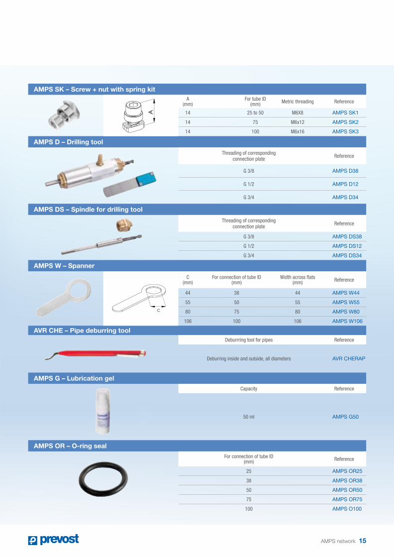
aMPS network 15
AMPS SK – Screw + nut with spring kitA
(mm)For tube ID
(mm) Metric threading Reference
14 25 to 50 M6X8 AMPS SK1
14 75 M6x12 AMPS SK2
14 100 M6x16 AMPS SK3
AMPS D – Drilling tool
Threading of corresponding connection plate Reference
G 3/8 AMPS D38
G 1/2 AMPS D12
G 3/4 AMPS D34
AMPS DS – Spindle for drilling tool
Threading of corresponding connection plate Reference
G 3/8 AMPS DS38
G 1/2 AMPS DS12
G 3/4 AMPS DS34
AMPS W – Spanner
C (mm)
For connection of tube ID (mm)
Width across flats (mm) Reference
44 38 44 AMPS W44
55 50 55 AMPS W55
80 75 80 AMPS W80
106 100 106 AMPS W106
AVR CHE – Pipe deburring toolDeburrring tool for pipes Reference
Deburring inside and outside, all diameters AVR CHERAP
AMPS G – Lubrication gelCapacity Reference
50 ml AMPS G50
AMPS OR – O-ring seal
For connection of tube ID (mm) Reference
25 AMPS OR25
38 AMPS OR38
50 AMPS OR50
75 AMPS OR75
100 AMPS O100
AA
C

Registered office : PRevoSt SaSParc d’activités des Glaisins – c.S. 9020874942 annecY-Le-vieUX cedeX – Francetél. + 33 (0)4 50 64 04 45 – Fax +33 (0)4 50 64 00 10e-mail : [email protected] – www.prevost.eu
the Pavilions – Bridgefold RoadRochdale oL11 5BX – United Kingdomtel. (+44) 0844 800 2788 – Fax (+44) 0844 800 2789e-mail: [email protected] – www.prevost.eu
Authorised distributor
Gra
phi
c d
esig
n: w
ww
.trip
tik.f
r -
Pho
to c
red
it: G
illes
Mar
guer
at
AMPS DOC15E
this document may not be deemed contractually binding.to provide better service for customers, Prevost reserves
the right to alter product characteristics without notice.Published by Prévost - March 2015


