66
OPERATION & MAINTENANCE A160-OM-C-MAY15

A-160Arrow Engine Company2301 East Independence • Tulsa, Oklahoma 74110fax (918) 699-2202local (918) 583-5711
(800) 331-3662 www. ArrowEngine.com
Waukesha®, VHP®, and VGF® are registered trademarks of Dresser Industries, Inc., Caterpillar®, is a registered trademark of Caterpillar, Inc., Fair-banks Morse® is a registered trademark of Coltec Industries, Inc., and Ajax® is a registered trademark of Cameron International Corporation.
Copyright © 2014 Arrow Engine Company
ENGINE COMPANYENGINES
GAS PRODUCTS
COMPRESSION
REPLACEMENT PARTS
C-SERIES C-46 C-66 C-96 C-101 C-106 C-255
A-SERIES A-32 A-42 A-54 A-62A-62 TurboA-62 Genset
A-90A-90 TurboA-90 Genset
A-160A-160 TurboA-160 Genset
K-SERIES K6
L-SERIES L-795
CATERPILLAR® G379 G398 G399 G3304 G3306
WAUKESHA® F2895F3521F5108
L5790L7042
P9390 145G/F817140G/F554
F18H24WAK/1197
FAIRBANKS® ZC-118 ZC-208 ZC-503 ZC-739 ZC-346
AJAX® 5× 6½ EA-22, 6½ × 8 CMAEA30, 7½ × 10 CMAEA-30, 7¼ × 8 CMAE-42, 8½ × 10 CMA
DP-60, 9½ × 10 CMADP-115/230, 13½ × 16DP-70/80/160, 11 × 14 CMA
GAS PRODUCTS Volume Tanks Suction Scrub-bers
Vertical and Horizontal Scrubbers
Meter Runs Coalescers Skids
CHEMICAL PUMPS 10 Series(beam operated)
12 Series(pneumatic)
430 Series(electric)
500 & 510 Series(penumatic)
Solar Chemical Pumps
COMPRESSION PRODUCTS
VRU-1 VRU-2 VRC-2 VRC-CNG VRS-2 Custom Compression Packages
OPERATION & MAINTENANCE A160-OM-C-MAy15

In 1955 Arrow Engine Company opened for business, beginning the tradition of providing premium service and exceptional products to the oil & gas industry, as well as the industrial engine market, throughout the world.
Arrow is a part of the Engineered Components segment formed by TriMas Corporation. Headquartered in Bloom� eld Hills, Michigan, TriMas Corporation (NASDAQ-TRS) provides engineered and applied products for growing markets worldwide.
With a consistent focus on our customers’ needs, striving to help them grow their business, and producing the most reliable equipment and parts in the industry, Arrow has forged a tradition of excellence since 1955.
ENGINE COMPANY
ENGINE COMPANY

3(800) 331-3662www.ArrowEngine.com
ENGINE COMPANY
A-160 OPERATION & MAINTENANCE
A-Series
A-160 Engine
A-160-OM-C-MAy15
Copyright © 2015 Arrow Engine Company, Tulsa, Oklahoma
2301 East Independence
Tulsa, Oklahoma 74110

4
TABLE OF CONTENTS
1 Forward 1
1.1 Safety Tips . . . . . . . . . . . . . . . . . . . . . . . . . . . . . . . . . . . . . . . . . . . . . . . . . . . . . . . . . . . . 11.2 Installation and Usage Tips . . . . . . . . . . . . . . . . . . . . . . . . . . . . . . . . . . . . . . . . . . . . . . . . . 11.3 General Specifications . . . . . . . . . . . . . . . . . . . . . . . . . . . . . . . . . . . . . . . . . . . . . . . . . . . . 2
2 Engine Overview 3
2.1 Engine Description . . . . . . . . . . . . . . . . . . . . . . . . . . . . . . . . . . . . . . . . . . . . . . . . . . . . . . . 32.1.1 Cylinder Heads . . . . . . . . . . . . . . . . . . . . . . . . . . . . . . . . . . . . . . . . . . . . . . . . . . . 32.1.2 Crankcase & Cylinder Liners . . . . . . . . . . . . . . . . . . . . . . . . . . . . . . . . . . . . . . . . . . 32.1.3 Rotating Assembly . . . . . . . . . . . . . . . . . . . . . . . . . . . . . . . . . . . . . . . . . . . . . . . . 32.1.4 Cooling System . . . . . . . . . . . . . . . . . . . . . . . . . . . . . . . . . . . . . . . . . . . . . . . . . . . 32.1.5 CD1 Ignition Systems . . . . . . . . . . . . . . . . . . . . . . . . . . . . . . . . . . . . . . . . . . . . . . 32.1.6 Lubrication System . . . . . . . . . . . . . . . . . . . . . . . . . . . . . . . . . . . . . . . . . . . . . . . . 32.1.7 Electrical Components . . . . . . . . . . . . . . . . . . . . . . . . . . . . . . . . . . . . . . . . . . . . . . 32.1.8 Liquid Cooled Exhaust Manifold . . . . . . . . . . . . . . . . . . . . . . . . . . . . . . . . . . . . . . . 32.1.9 Engine Numbering System . . . . . . . . . . . . . . . . . . . . . . . . . . . . . . . . . . . . . . . . . . . 3
2.2 Diagram of A-160 Engine . . . . . . . . . . . . . . . . . . . . . . . . . . . . . . . . . . . . . . . . . . . . . . . . . . 42.3 Diagram of Arrow A-160 Engine - Left Side . . . . . . . . . . . . . . . . . . . . . . . . . . . . . . . . . . . . . 52.4 Diagram of Arrow A-160 Engine - Right Side . . . . . . . . . . . . . . . . . . . . . . . . . . . . . . . . . . . . 6
3 Torque Specifications 7
3.1 Torque Specifications . . . . . . . . . . . . . . . . . . . . . . . . . . . . . . . . . . . . . . . . . . . . . . . . . . . . . 73.3 Flywheel Bolt Sequence . . . . . . . . . . . . . . . . . . . . . . . . . . . . . . . . . . . . . . . . . . . . . . . . . . . 83.2 Torque Specifications . . . . . . . . . . . . . . . . . . . . . . . . . . . . . . . . . . . . . . . . . . . . . . . . . . . . . 83.4 Head Torque Sequence . . . . . . . . . . . . . . . . . . . . . . . . . . . . . . . . . . . . . . . . . . . . . . . . . . . 9
3.4.1 Tightening Sequence . . . . . . . . . . . . . . . . . . . . . . . . . . . . . . . . . . . . . . . . . . . . . . . 93.5 Main Cap Torquing Sequence . . . . . . . . . . . . . . . . . . . . . . . . . . . . . . . . . . . . . . . . . . . . . . . 9
3.5.1 Torque Methods . . . . . . . . . . . . . . . . . . . . . . . . . . . . . . . . . . . . . . . . . . . . . . . . . . 9
4 Fuel, Lubricating Oil, and Coolant 10
4.1 Lubrication Guide . . . . . . . . . . . . . . . . . . . . . . . . . . . . . . . . . . . . . . . . . . . . . . . . . . . . . . . 104.2 Fuel System . . . . . . . . . . . . . . . . . . . . . . . . . . . . . . . . . . . . . . . . . . . . . . . . . . . . . . . . . . 114.3 Exhaust System . . . . . . . . . . . . . . . . . . . . . . . . . . . . . . . . . . . . . . . . . . . . . . . . . . . . . . . . 124.4 Cooling System . . . . . . . . . . . . . . . . . . . . . . . . . . . . . . . . . . . . . . . . . . . . . . . . . . . . . . . . 134.5 Fuel . . . . . . . . . . . . . . . . . . . . . . . . . . . . . . . . . . . . . . . . . . . . . . . . . . . . . . . . . . . . . . . . 13
4.5.1 Fuel Systems Natural Gas Carburetion . . . . . . . . . . . . . . . . . . . . . . . . . . . . . . . . . . 134.6 Firing Order. . . . . . . . . . . . . . . . . . . . . . . . . . . . . . . . . . . . . . . . . . . . . . . . . . . . . . . . . . . 144.7 Valve Specifications . . . . . . . . . . . . . . . . . . . . . . . . . . . . . . . . . . . . . . . . . . . . . . . . . . . . . 144.8 Air System . . . . . . . . . . . . . . . . . . . . . . . . . . . . . . . . . . . . . . . . . . . . . . . . . . . . . . . . . . . 144.9 Electrical System . . . . . . . . . . . . . . . . . . . . . . . . . . . . . . . . . . . . . . . . . . . . . . . . . . . . . . . 14
i
i(800) 331-3662www.ArrowEngine.com
4.10 EDG 5500 Electronic Digital Governor . . . . . . . . . . . . . . . . . . . . . . . . . . . . . . . . . . . . . . . . 144.10.1 Installation . . . . . . . . . . . . . . . . . . . . . . . . . . . . . . . . . . . . . . . . . . . . . . . . . . . . . 144.10.2 Basic Wiring (Terminals A-F) . . . . . . . . . . . . . . . . . . . . . . . . . . . . . . . . . . . . . . . . 144.10.3 Additional Wiring (Terminals G-P) . . . . . . . . . . . . . . . . . . . . . . . . . . . . . . . . . . . . . 144.10.4 Display and Controls . . . . . . . . . . . . . . . . . . . . . . . . . . . . . . . . . . . . . . . . . . . . . . 154.10.5 Parameters . . . . . . . . . . . . . . . . . . . . . . . . . . . . . . . . . . . . . . . . . . . . . . . . . . . . . 154.10.6 Troubleshooting . . . . . . . . . . . . . . . . . . . . . . . . . . . . . . . . . . . . . . . . . . . . . . . . . 164.10.7 Specifications . . . . . . . . . . . . . . . . . . . . . . . . . . . . . . . . . . . . . . . . . . . . . . . . . . . 17
4.11 ESD5100 Series Speed Control Unit Specifications . . . . . . . . . . . . . . . . . . . . . . . . . . . . . . . 174.11.1 Introduction . . . . . . . . . . . . . . . . . . . . . . . . . . . . . . . . . . . . . . . . . . . . . . . . . . . . 174.11.2 Description . . . . . . . . . . . . . . . . . . . . . . . . . . . . . . . . . . . . . . . . . . . . . . . . . . . . . 174.11.3 Installation . . . . . . . . . . . . . . . . . . . . . . . . . . . . . . . . . . . . . . . . . . . . . . . . . . . . . 22
5 Operation 26
5.1 Lifting Engine . . . . . . . . . . . . . . . . . . . . . . . . . . . . . . . . . . . . . . . . . . . . . . . . . . . . . . . . . 265.2 Air Intake System . . . . . . . . . . . . . . . . . . . . . . . . . . . . . . . . . . . . . . . . . . . . . . . . . . . . . . 265.3 Flywheel, Housing Runout, & Crankshaft Endplay . . . . . . . . . . . . . . . . . . . . . . . . . . . . . . . . 265.4 Before Starting . . . . . . . . . . . . . . . . . . . . . . . . . . . . . . . . . . . . . . . . . . . . . . . . . . . . . . . . 28
5.4.1 Filling Engine with Oil . . . . . . . . . . . . . . . . . . . . . . . . . . . . . . . . . . . . . . . . . . . . . 285.4.2 Filling Cooling Fluid . . . . . . . . . . . . . . . . . . . . . . . . . . . . . . . . . . . . . . . . . . . . . . . 285.4.3 Attaching Gas Line . . . . . . . . . . . . . . . . . . . . . . . . . . . . . . . . . . . . . . . . . . . . . . . 28
5.5 Startup . . . . . . . . . . . . . . . . . . . . . . . . . . . . . . . . . . . . . . . . . . . . . . . . . . . . . . . . . . . . . . 285.5.1 Quick Trouble Check Chart . . . . . . . . . . . . . . . . . . . . . . . . . . . . . . . . . . . . . . . . . . 29
5.6 Manual Oil Priming Pump . . . . . . . . . . . . . . . . . . . . . . . . . . . . . . . . . . . . . . . . . . . . . . . . . 295.6.1 Break-In Procedure . . . . . . . . . . . . . . . . . . . . . . . . . . . . . . . . . . . . . . . . . . . . . . . 305.6.2 Exercise of Standby Unit . . . . . . . . . . . . . . . . . . . . . . . . . . . . . . . . . . . . . . . . . . . 305.6.3 Light Load Operation . . . . . . . . . . . . . . . . . . . . . . . . . . . . . . . . . . . . . . . . . . . . . . 305.6.4 Engine Warm-up . . . . . . . . . . . . . . . . . . . . . . . . . . . . . . . . . . . . . . . . . . . . . . . . . 305.6.5 Governor Speed Setting . . . . . . . . . . . . . . . . . . . . . . . . . . . . . . . . . . . . . . . . . . . . 31
5.7 Stopping the Engine . . . . . . . . . . . . . . . . . . . . . . . . . . . . . . . . . . . . . . . . . . . . . . . . . . . . . 31
6 Maintenance 32
6.1 Engine Performance Record . . . . . . . . . . . . . . . . . . . . . . . . . . . . . . . . . . . . . . . . . . . . . . . 326.1.1 Fuels . . . . . . . . . . . . . . . . . . . . . . . . . . . . . . . . . . . . . . . . . . . . . . . . . . . . . . . . . 32
6.2 Maintenance Procedures. . . . . . . . . . . . . . . . . . . . . . . . . . . . . . . . . . . . . . . . . . . . . . . . . . 326.2.1 Air Filter . . . . . . . . . . . . . . . . . . . . . . . . . . . . . . . . . . . . . . . . . . . . . . . . . . . . . . . 326.2.2 Check Connection Bolt . . . . . . . . . . . . . . . . . . . . . . . . . . . . . . . . . . . . . . . . . . . . . 326.2.3 Check Belts and Tensioners . . . . . . . . . . . . . . . . . . . . . . . . . . . . . . . . . . . . . . . . . 336.2.4 Cooling System . . . . . . . . . . . . . . . . . . . . . . . . . . . . . . . . . . . . . . . . . . . . . . . . . . 336.2.5 Antifreeze . . . . . . . . . . . . . . . . . . . . . . . . . . . . . . . . . . . . . . . . . . . . . . . . . . . . . . 336.2.6 Anticorrosive agent . . . . . . . . . . . . . . . . . . . . . . . . . . . . . . . . . . . . . . . . . . . . . . . 336.2.7 Thermostat . . . . . . . . . . . . . . . . . . . . . . . . . . . . . . . . . . . . . . . . . . . . . . . . . . . . . 346.2.8 Thermostat Removal and Testing . . . . . . . . . . . . . . . . . . . . . . . . . . . . . . . . . . . . . 346.2.9 Cleaning the Cooling System . . . . . . . . . . . . . . . . . . . . . . . . . . . . . . . . . . . . . . . . 346.2.10 Oil Consumption . . . . . . . . . . . . . . . . . . . . . . . . . . . . . . . . . . . . . . . . . . . . . . . . . 346.2.11 Oil Changes . . . . . . . . . . . . . . . . . . . . . . . . . . . . . . . . . . . . . . . . . . . . . . . . . . . . 34
ii

ii
16.3 Cold Weather Operation . . . . . . . . . . . . . . . . . . . . . . . . . . . . . . . . . . . . . . . . . . . . . . . . . . 35
6.3.1 Oil Filters . . . . . . . . . . . . . . . . . . . . . . . . . . . . . . . . . . . . . . . . . . . . . . . . . . . . . . 356.3.2 Centrifuge Oil Filter . . . . . . . . . . . . . . . . . . . . . . . . . . . . . . . . . . . . . . . . . . . . . . . 356.3.3 Cleaning frequency: . . . . . . . . . . . . . . . . . . . . . . . . . . . . . . . . . . . . . . . . . . . . . . 366.3.4 Identification and Location . . . . . . . . . . . . . . . . . . . . . . . . . . . . . . . . . . . . . . . . . . 366.3.5 Servicing Instructions: . . . . . . . . . . . . . . . . . . . . . . . . . . . . . . . . . . . . . . . . . . . . . 366.3.6 Servicing Procedure: . . . . . . . . . . . . . . . . . . . . . . . . . . . . . . . . . . . . . . . . . . . . . . 366.3.7 Centrifuge Cleaner Check Points . . . . . . . . . . . . . . . . . . . . . . . . . . . . . . . . . . . . . . 386.3.8 Centrifuge Cleaner Do Not’s . . . . . . . . . . . . . . . . . . . . . . . . . . . . . . . . . . . . . . . . . 38
6.4 Troubleshooting Chart . . . . . . . . . . . . . . . . . . . . . . . . . . . . . . . . . . . . . . . . . . . . . . . . . . . 396.5 Spark Plug Adjustments . . . . . . . . . . . . . . . . . . . . . . . . . . . . . . . . . . . . . . . . . . . . . . . . . . 396.6 Adjusting the Carburetor . . . . . . . . . . . . . . . . . . . . . . . . . . . . . . . . . . . . . . . . . . . . . . . . . 406.7 Speed Control Unit . . . . . . . . . . . . . . . . . . . . . . . . . . . . . . . . . . . . . . . . . . . . . . . . . . . . . . 40
6.7.1 Idle Speed Setting . . . . . . . . . . . . . . . . . . . . . . . . . . . . . . . . . . . . . . . . . . . . . . . . 406.8 Integral Throttle Body Actuator . . . . . . . . . . . . . . . . . . . . . . . . . . . . . . . . . . . . . . . . . . . . . 40
6.8.1 Idle Adjustment . . . . . . . . . . . . . . . . . . . . . . . . . . . . . . . . . . . . . . . . . . . . . . . . . 406.8.2 Wiring . . . . . . . . . . . . . . . . . . . . . . . . . . . . . . . . . . . . . . . . . . . . . . . . . . . . . . . . 416.8.3 EMI (Defined) . . . . . . . . . . . . . . . . . . . . . . . . . . . . . . . . . . . . . . . . . . . . . . . . . . . 41
6.9 Maintenance Schedule . . . . . . . . . . . . . . . . . . . . . . . . . . . . . . . . . . . . . . . . . . . . . . . . . . . 41
7 Engine Storage 43
7.1 Basic Requirements . . . . . . . . . . . . . . . . . . . . . . . . . . . . . . . . . . . . . . . . . . . . . . . . . . . . . 437.2 Storing New Engines . . . . . . . . . . . . . . . . . . . . . . . . . . . . . . . . . . . . . . . . . . . . . . . . . . . . 44
7.2.1 Engine in Operable Condition . . . . . . . . . . . . . . . . . . . . . . . . . . . . . . . . . . . . . . . . 447.2.2 When Engine is Not Operable . . . . . . . . . . . . . . . . . . . . . . . . . . . . . . . . . . . . . . . . 44
7.3 Storing Engines That Have Been In Service . . . . . . . . . . . . . . . . . . . . . . . . . . . . . . . . . . . . 457.3.1 Engine in Operable Condition . . . . . . . . . . . . . . . . . . . . . . . . . . . . . . . . . . . . . . . . 457.3.2 When Engine is Not Operable . . . . . . . . . . . . . . . . . . . . . . . . . . . . . . . . . . . . . . . . 45
7.4 Preservative Oil . . . . . . . . . . . . . . . . . . . . . . . . . . . . . . . . . . . . . . . . . . . . . . . . . . . . . . . . 457.5 Post Storage Engine Preparation . . . . . . . . . . . . . . . . . . . . . . . . . . . . . . . . . . . . . . . . . . . . 45
7.5.1 Requirements . . . . . . . . . . . . . . . . . . . . . . . . . . . . . . . . . . . . . . . . . . . . . . . . . . . 45
8 Troubleshooting 47
8.1 Methods . . . . . . . . . . . . . . . . . . . . . . . . . . . . . . . . . . . . . . . . . . . . . . . . . . . . . . . . . . . . . 478.2 Operating Controls . . . . . . . . . . . . . . . . . . . . . . . . . . . . . . . . . . . . . . . . . . . . . . . . . . . . . . 478.3 Electrical System . . . . . . . . . . . . . . . . . . . . . . . . . . . . . . . . . . . . . . . . . . . . . . . . . . . . . . . 478.4 Cooling System . . . . . . . . . . . . . . . . . . . . . . . . . . . . . . . . . . . . . . . . . . . . . . . . . . . . . . . . 478.5 Air Intake System . . . . . . . . . . . . . . . . . . . . . . . . . . . . . . . . . . . . . . . . . . . . . . . . . . . . . . 478.6 Exhaust System . . . . . . . . . . . . . . . . . . . . . . . . . . . . . . . . . . . . . . . . . . . . . . . . . . . . . . . . 488.7 Troubleshooting Chart . . . . . . . . . . . . . . . . . . . . . . . . . . . . . . . . . . . . . . . . . . . . . . . . . . . 49

1(800) 331-3662www.ArrowEngine.com
11 Forward
This manual introduces how to use, maintain, and repair the A-160 engine, and is intended for use as a reference guide for operators and tech-nicians. Thorough knowledge of the structure of the engine as well as proper maintenance proce-dures will enhance the efficiency and service life of this engine.
1.1 Safety Tips
To avoid accidental danger or loss due to im-proper handling, please read the following precautions carefully before you install and use your engine.
1. The operator should thoroughly read this manual and adhere to the recommended operation and maintenance specifications.
2. Prevent burns by avoiding contact with high temperature components such as the ex-haust pipe and turbocharger.
3. Allow the engine to cool before opening the water inlet of the radiator to prevent high temperature steam burns.
4. The engine should be operated in a well ventilated area to prevent possible buildup of toxic gases.
1.2 Installation and Usage Tips
1. The bolts of the main bearing, connecting rod and cylinder head have strict torque and turning angle requirements. Refer to the torque specifications in chapter 2. Failure to follow these specifications will lead to engine damage and invalidates the warranty.
2. Operating the engine without an air filter may cause abnormal wear.
4. A 50-hour break-in period is recommended for a new engine, with minimum of a half load and a maximum full load.
5. Check the coolant and engine oil levels be-fore each engine start up.
6. For smoother start up, manually pump lubri-cating oil to the lubrication circuit and vari-ous lubrication points via the hand oil pump each time the engine is used. This may also extend the life of the engine.
7. After a cold start, idle the engine for 5-10 minutes to allow it to warm up before in-creasing load. When the cooling water temperature is lower than 100°F, do not run under high speed or with a large load. Before engine shutdown, a cool down period is rec-ommended.
8. The engine should not be operated at idle speed for long periods of time. As a rule of thumb, the idle operation should be no more than 10 min.

2
1 1.3 General Specifications
PARAMETER A-160 NA
Number of cylinders 6
Cylinder arrangement In-line
Working Cycle 4-stroke Natural Gas Engine
4-valve cylinder arrangement 4 valves per cylinder
Fuel System Carburetor
Cooling System Liquid Cooled
Direction of Rotation Counter clockwise looking at flywheel end
Number of teeth on flywheel 178
Compression Ratio 10:1
Bore 5.904 in. (150 mm)
Stroke 5.904 in. (150 mm)
Bore X Stroke 970 cu. in. (15.9 L)
Swept Volume / Cylinder 162 cu. in. (2.65 L)
Firing Order 1-5-3-6-2-4 (from flywheel end)
Intake and Exhaust Valve Lash (warm) .013 in (.33 mm)
Starter 24V electric starter
BMEP @ 1800 rpm Continuous Power 93.3
Rated HP @ 1800 RPM Continuous 215
Rated HP @ 1800 RPM Intermittent 236
Maximum Operating Speed 1800 rpm
Fuel Pressure 4 - 8 inches water 4 - 8 psi from main regulator
Engine weight with flywheel, housing, and radiator
Power Unit (open) 6750 lbs
Genset Unit (open) 8000 lbs
Fuel Consumption BTU / HR = 8628 @ 1800
Oil Consumption Max .004 LBS / HP-HR

3(800) 331-3662www.ArrowEngine.com
22 Engine Overview
2.1 Engine Description
2.1.1 Cylinder HeadsThe individual 4-valve cylinder heads are made of cast iron equipped with helical inlet ports de-signed for air and fuel efficiency. The heads have a specially designed gasket that provides reliable sealing of the fuel, coolant, and oil passages. The intake and exhaust valves are made of high temperature resistant material.
2.1.2 Crankcase & Cylinder LinersThe cylinder liner o-rings provide an excellent oil and coolant seal on the outer diameter while the inner diameter is plateau honed. The cylinder liners are centrifugal cast.
2.1.3 Rotating Assembly The pistons are made of an aluminum alloy which is lower in weight, has good thermal con-ductivity, and offers higher temperature stability. The connecting rods and crankshaft are de-signed to accommodate a wide range of loads. The bearings are designed to withstand the higher stresses due to the combustion process. The special design of the spray nozzle protects the piston from overheating and seizing. The forged crankshaft is provided with two coun-terweights for each crank pin, giving it the best dynamic balance and reduced bearing loads.
2.1.4 Cooling SystemThe cast in coolant passages and integrated twin thermostats provide for maximum efficiency of the cooling system.
2.1.5 CD1 Ignition SystemsCD1 is a capacitor-discharge, electronic micro-circuit based ignition system for 1 to 8 cylinder industrial engines. It may be powered by either 8 to 30 VDC, and has no moving parts. It works with the step-up coils (one per cylinder.)
Engine timing should be set to 28° BTDC.
Employing digital circuitry, the CD1 unit process-es signal from a magnetic pickup, sensing drilled
reference holes or protrusions. This provides ac-curate and consistent timing referenced directly to the crankshaft or camshaft. The CD1 uses high energy, capacitor-discharge principle which provides maximum engine performance and can extend spark plug life three to five times when compared to an inductive system. Indicating LED’s convey whether proper pickup signals are being received and if the corresponding output signals are correct.
2.1.6 Lubrication SystemThe A-160 engine is equipped with an oil pump that is driven by the crankshaft through an inter-mediate gear. The lubricating oil is drawn from the crankcase and passes through an oil/water heat exchanger which results in faster engine warm up and maximum oil cooling, providing the best lubricating quality. Contaminates are filtered by a combination of disposable cartridges and a large centrifuge in the bypass circuit.
2.1.7 Electrical ComponentsA-160 engines are provided with a heavy-duty 24-volt starter for reliable operation. The engine is also equipped with a 63 amperage charging system.
2.1.8 Liquid Cooled Exhaust Manifold
The A-160 is equipped with a liquid cooled ex-haust manifold, which reduces the surface tem-perature and radiant heat transfer, thus lowering the risk of heat related damage to vital engine components.
2.1.9 Engine Numbering SystemThe model designation, engine rating, and engine serial number are documented on a nameplate which is attached to the right side of the engine block. When ordering parts or cor-respondence related to the engine it is essential to provide the model designation and complete engine serial number.

4
2 1
2
3
4
5
6
2.2 Diagram of A-160 Engine
1. Muffler
2. Radiator
3. Base
4. Generator
5. Air Cleaner
6. Muffler Frame

5(800) 331-3662www.ArrowEngine.com
22.3 Diagram of Arrow A-160 Engine - Left Side
7. Radiator Supports
8. Exhaust Pipe
9. Isolators
10. Fan
7
910
8

6
2 2.4 Diagram of Arrow A-160 Engine - Right Side
11. ECM
12. Rain Cap
13. Lower Radiator Pipe
14. Carburetor
15. Oil Filters/Spinner Assembly (top)
16. Electrical Control Box
17. Air Cleaner
18. Water Pump
11
12
1314 15
16
17
18

7(800) 331-3662www.ArrowEngine.com
33 Torque Specifications
Torque (Ft/lbs/Degrees)
FASTENER SIZE STAGE 1
STAGE 2
STAGE 3
STAGE 4
STAGE 5
Cylinder Head Bolts M16 M20
59 59
60° 60°
60° —
— 60°
— 60°
Connecting Rod Bolts
M16X1.5X73 52 148 258
Main Bearing Cap Bolts
M16X150 60 90 200 405
Balance Weight Bolt M16X50 75 100 145
Flywheel Bolt M16X45 52 148 295
Crank Pulley Bolt M20X1.5X65 314
Flywheel Housing Bolt M12X55 59
Rocker Arm Support Bolt
M10X80 35
Liquid Cooled Manifold Nut
M10 35
Insulator Bolts 50
Front Pulley Fastening Bolts
162
*As per international standards.
• Threads and seating surfaces of fasteners should be cleaned and coated with engine oil before assembly.
• When replacing main or connecting rod bearings during overhaul, always use new bolts for main bearing cap and connecting rods.
• Apply initial torque and tighten the bolts according to the torques in stages as specified in the table on the next page.
• As per international standards all M8X1.25 screws/bolts of 8.8 quality must be torqued to 18 ft/lbs.
• As per international standards all M10X1.5 screw/bolts of 8.8 quality must be torqued to 34 ft/lbs.
3.1 Torque Specifications

8
3 3.2 Torque Specifications
Apply lubricant on the thread, support surface of the bolts, and screw down all the nuts. Then tighten according to method below.
TORQUE SPECIFICATIONS
BOLT SIZE FT/LBS
M4 2
M5 4
M6 7
M8 17
M10 34
M12 59
M14 92
M16 144
M18 199
M20 284
M22 376
M24 487
M27 723
M30 996
M8X1 18
M10X1.25 36
M12X1.25 65
M12X1.5 61
M14X1.5 103
M16X1.5 155
M18X1.5 225
M20X1.5 313
M22X1.5 420
M24X1.5 531
M27X1.5 774
M30X1.5 1069
3.3 Flywheel Bolt Sequence
198
5
4
102
7
6
3
Flywheel Bolt Torque
Stage 1 Stage 2 Stage 3
52 148 295

9(800) 331-3662www.ArrowEngine.com
3
E K
3
4
2
5
7 6
8 9
11
12
10
1 13
1415
16 17
1819
20 21
2223
24
A
B
C
D
E
F
G
H
I
J
K
L
M
N
3.4 Head Torque Sequence
3.5 Main Cap Torquing Sequence
A
B
C
D
E
F
G
H
I
J
K
L
M
N
3.4.1 Tightening SequenceTighten bolts numbered 1-24 in numeric order, then tighten bolts labeled A-N in alphabetical order. See section 3.1 for torque specifications.
Inside
Outside
3.5.1 Torque MethodsTighten all main bearing cap secondary bolts twice in alphabetical order until the recommended 200 ft/lbs is achieved. Then complete torque specification to 405 ft/lbs.

10
4 4 Fuel, Lubricating Oil, and Coolant
LUBRICATION SYSTEM SPECIFICATIONS
Type of lubrication Forced feed lubrication with gear pump
Oil Filters 2 spin on paper filters in main stream and 1 centrifuge filter in bypass
Oil type Refer to Oil Recommendations tables
Oil capacity - Oil change 52-55 Qt
Coolant Capacity 33 Gal
NOTESynthetic lubricating oils are not recommended by Arrow Engine Company.
Service ConditionsEngine load, temperature, fuel quality, atmo-spheric dirt, moisture and maintenance will al be factors that influence oil performance. If oil performance problems arise or are anticipated, the oil supplier should be consulted.
Extended oil change intervals should be utilized with caution on any engine using highly disper-sant oils. The dispersants function by absorption of particles of contaminants. However, when dispersant saturation is reached, these oils tend to “dump out” all of the suspended contaminants in a relatively short period of time. Laboratory analysis will not predict the “dump out” point precisely. Consequently, closer operator attention to engine conditions is required when establishing an extended oil change interval.
For fuels with hydrogen sulfide, operator should consult the factory for recommenda-tions/requirements. When fuel is burned in an engine combustion chamber, any sulfur it contains is converted to sulfur oxides, which will combine with water vapor to form acids. These acids can cause serious corrosive damage to engine com-ponents. The engine oil should be compounded
4.1 Lubrication Guide
Lubrication intervals listed are for normal oper-ating conditions and should coincide with other preventive maintenance services. For extreme operating conditions outside the norm, equip-ment should be inspected more frequently and lubrication intervals shortened if there is evi-dence of dirt, sludge, or breakdown of lubricant.
Keep all lubricants in closed containers and store them in a clean dry place away from heat. Always protect the lubricants from dust, dirt, or moisture. Keep lubrication equipment clean and ready for use at all times.
Before lubricating, wipe surrounding areas clean to prevent dirt or other foreign matter from en-tering the lubrication system. Use a cloth moist-ened with solvent to remove any old or hard-ened lubricants. After lubricating, remove any excess lubricant and wipe any spilled lubricant from parts not requiring lubrication.
Lubricating OilsThe performance of a lubricant, like that of any manufactured product, is the responsibility of the refiner and producer. The engine operator also controls the oil’s performance by making decisions about performing oil changes, filter changes, loads, general maintenance, and oper-ating conditions.

11(800) 331-3662www.ArrowEngine.com
4to neutralize the acids and inhibit corrosion. This is done by building alkalinity into the oil via the additive formulation. The commonly used mea-sure of relative alkalinity is termed “Total Base Number” (TBN). The higher the number, the greater the reserve alkalinity or acid neutralizing capacity of an oil.
Lube oil suppliers will supply information about the TBN levels of their products. An oil analysis program will keep the user informed of the TBN level of his oil in service so that adequate corro-sion protection is maintained.
Since low operating temperatures promote con-densation of acid-bearing fumes in the crank-case, engine coolant temperatures should also be maintained at 185°F (85°C) minimum.
Selecting Oil ViscosityThe correct lubricating oil viscosity, often re-ferred to as weight, must be determined with the engine operating under its normal load speed and temperature.
Start and load engine as described under the start up section.
After oil and coolant temperatures stabilize, note the temperature of the oil in the oil pan. Use an accurate temperature gauge. Compare this tem-perature with the following chart. The correct oil viscosity will be found in the right hand column.
OIL TEMPERATURES METHODOIL PAN OPERATING
TEMPERATURESSAE
VISCOSITY NUMBERS
210°F - 250°F (99°C - 121°C)
40
160°F - 210°F (71°C - 99°C)
30
130°F - 160°F (54°C - 70°C)
20
Engines operating with low oil temperatures – below 160°F (71.1°C) – can be expected to show excessive sludge and wear. Engines oper-ating with high oil temperatures – above 230°F (110°C) – may experience lacquering and ring sticking due to oil oxidation. If oil temperatures cannot be corrected to the normal operating
range, more frequent oil changes may help in extending engine life.
When the actual operating oil temperature is not known, an estimate of the SAE oil grade to use can be made by assuming the oil pan operat-ing temperature will be 120°F (48.9°C) degrees above the ambient air temperature in heavy duty service. For example, at an ambient air temperature of 70°F (21.1°C), estimated oil pan operating temperature would be 190°F (87.7°C). Use SAE 30 as indicated in the Oil Temperature Method table.
NOTEThis is only an estimate since the type of instal-lation determines the amount of air circulation for cooling around the oil pan. Actual oil pan operat-ing temperatures should be measured whenever possible.
Multi-viscosity oils, 10W30 for example, should be used only when cold starting conditions make it absolutely necessary. Oil change periods should be reduced by 50% for engines using multi-viscosity oil because multi-viscosity oils may rapidly lose their highest viscosity rating in industrial service
4.2 Fuel System
The major components in the natural gas fuel system are the regulators, coalescent filter, pip-ing and the carburetor system.
Pressure regulators are designed to control the pressure of the gas as it enters the engine. Through an arrangement of a diaphragm and springs, the pressure of the natural gas coming into the engine is lowered and controlled. This supplies a constant steady supply of gas to the carburetor.

12
4
Figure 1. Figure 4.1 Natural Gas Regulator
There are two types of pressure regulators in the fuel system: a high pressure line, or “Big Joe”, regulator mounted near the main fuel line, and a low pressure engine regulator.
The line regulator brings the pressure in the lines leading to the engine regulator to 4-6 psi (.35 - .70 kg/cm2). The engine regulator sets the gas pressure to the carburetor at 1” - 4” (127 + 13 mm) of water column (less than 1 psi). From the engine mounted regulator the gas flows into the carburetor. Air is mixed with the gas, and it flows into the engine to be burned.
Gas pressure to the engine regulator must be 4-6 psi (.35 - .70 kg/cm2) max. Low gas pressure will starve the engine of fuel and reduce engine output. High pressures could damage the regula-tor, allowing excessive fuel to flood the cylinders. This could lead to detonation and serious en-gine/carburetor damage.
If possible, avoid fueling any gas operated equipment off of the supply line between the line regulator and the engine regulator. The sup-ply pressure to the engine could be disrupted. If there is no way to avoid such an installation, add a second line regulator close to the engine and increase the pressure from the first line regula-
tor by 10 psi (.70 kg/cm2) to compensate for the pressure loss.
Regulators must be spaced according to the inner diameter of the pipe used. For a general rule of thumb, the maximum allowable distance between regulators is eight times the pipe ID. For example, with a 2” pipe, the maximum distance between the regulators is 16” (406.4 mm). Regulators must be mounted in an upright position.
The maximum pressure drop across a line regu-lator is generally 50-75 psi (3.5-5.3 kg/cm2). Consult the regulator manufacturer for specific information.
4.3 Exhaust System
Engine exhaust system restriction must be kept to a minimum. The adverse effects of excessive back pressure include loss of power, poor fuel economy, excessive valve temperatures, and engine overheating. Check for undersized piping, a restricted silencer or muffler, or excessive turns or bends in the system if exhaust restriction is excessive.
Exhaust pipes must be adequately sized and supported using long radius elbows. The radius of the turn should be at least 4 to 5 times the pipe diameter to prevent restriction. Multiple connections to a common header are not recom-mended as this can result in erratic operation and potential engine damage. Locate the si-lencer as close to the engine as possible to help prevent pulsing effects.
Attention must be given to adequate silencing of the engine as unnecessary noise may, over time, damage the hearing of the operator and become a public nuisance. Objectionable noise is unnec-essary today with the available mufflers which can be used to control the exhaust.
CAUTIONMaximum distortion of flexible exhaust connec-tor, due to connected exhaust piping is ± ¼ inch (6.35 mm) offset and ± ¼ inch (6.35 mm) axial deflection.
13(800) 331-3662www.ArrowEngine.com
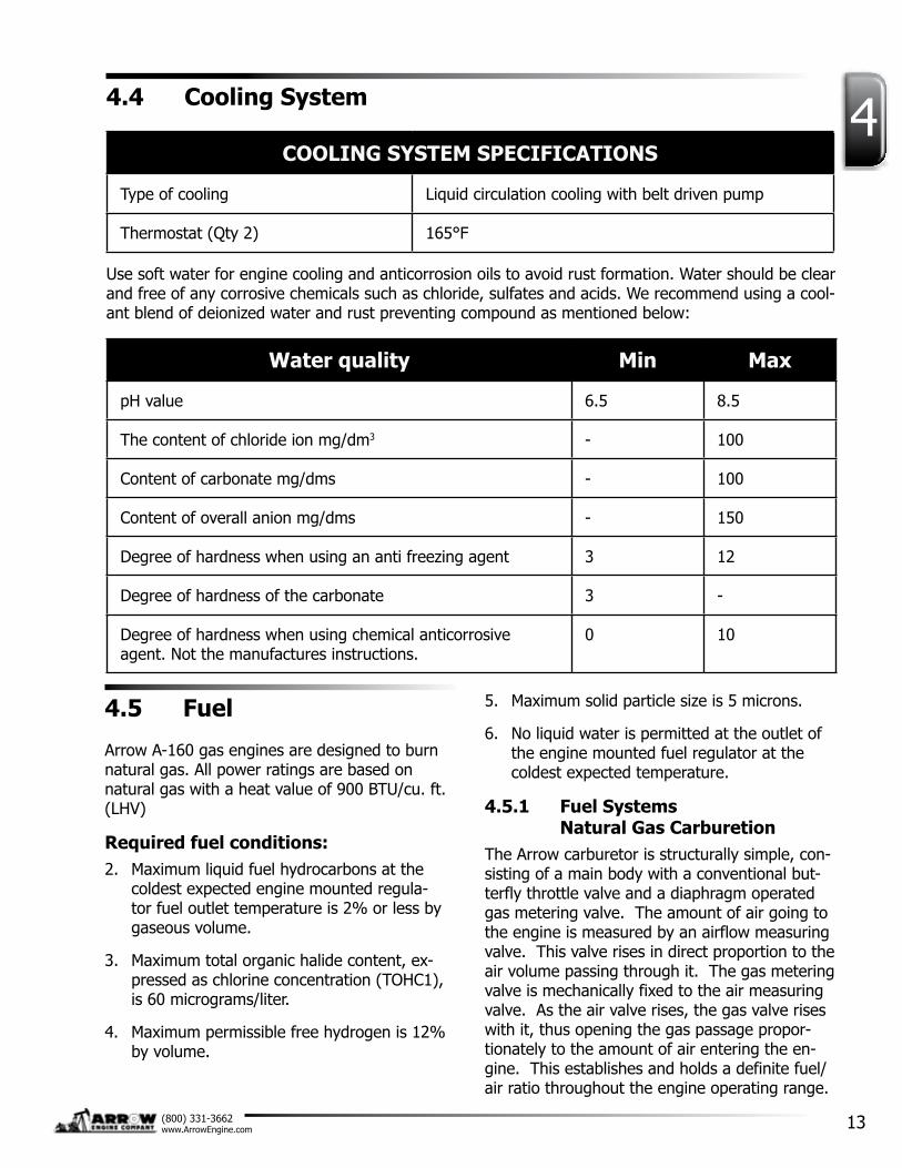
44.4 Cooling System
COOLING SYSTEM SPECIFICATIONS
Type of cooling Liquid circulation cooling with belt driven pump
Thermostat (Qty 2) 165°F
Use soft water for engine cooling and anticorrosion oils to avoid rust formation. Water should be clear and free of any corrosive chemicals such as chloride, sulfates and acids. We recommend using a cool-ant blend of deionized water and rust preventing compound as mentioned below:
Water quality Min Max
pH value 6.5 8.5
The content of chloride ion mg/dm3 - 100
Content of carbonate mg/dms - 100
Content of overall anion mg/dms - 150
Degree of hardness when using an anti freezing agent 3 12
Degree of hardness of the carbonate 3 -
Degree of hardness when using chemical anticorrosive agent. Not the manufactures instructions.
0 10
4.5 Fuel
Arrow A-160 gas engines are designed to burn natural gas. All power ratings are based on natural gas with a heat value of 900 BTU/cu. ft. (LHV)
Required fuel conditions:2. Maximum liquid fuel hydrocarbons at the
coldest expected engine mounted regula-tor fuel outlet temperature is 2% or less by gaseous volume.
3. Maximum total organic halide content, ex-pressed as chlorine concentration (TOHC1), is 60 micrograms/liter.
4. Maximum permissible free hydrogen is 12% by volume.
5. Maximum solid particle size is 5 microns.
6. No liquid water is permitted at the outlet of the engine mounted fuel regulator at the coldest expected temperature.
4.5.1 Fuel Systems Natural Gas Carburetion
The Arrow carburetor is structurally simple, con-sisting of a main body with a conventional but-terfly throttle valve and a diaphragm operated gas metering valve. The amount of air going to the engine is measured by an airflow measuring valve. This valve rises in direct proportion to the air volume passing through it. The gas metering valve is mechanically fixed to the air measuring valve. As the air valve rises, the gas valve rises with it, thus opening the gas passage propor-tionately to the amount of air entering the en-gine. This establishes and holds a definite fuel/air ratio throughout the engine operating range.
14
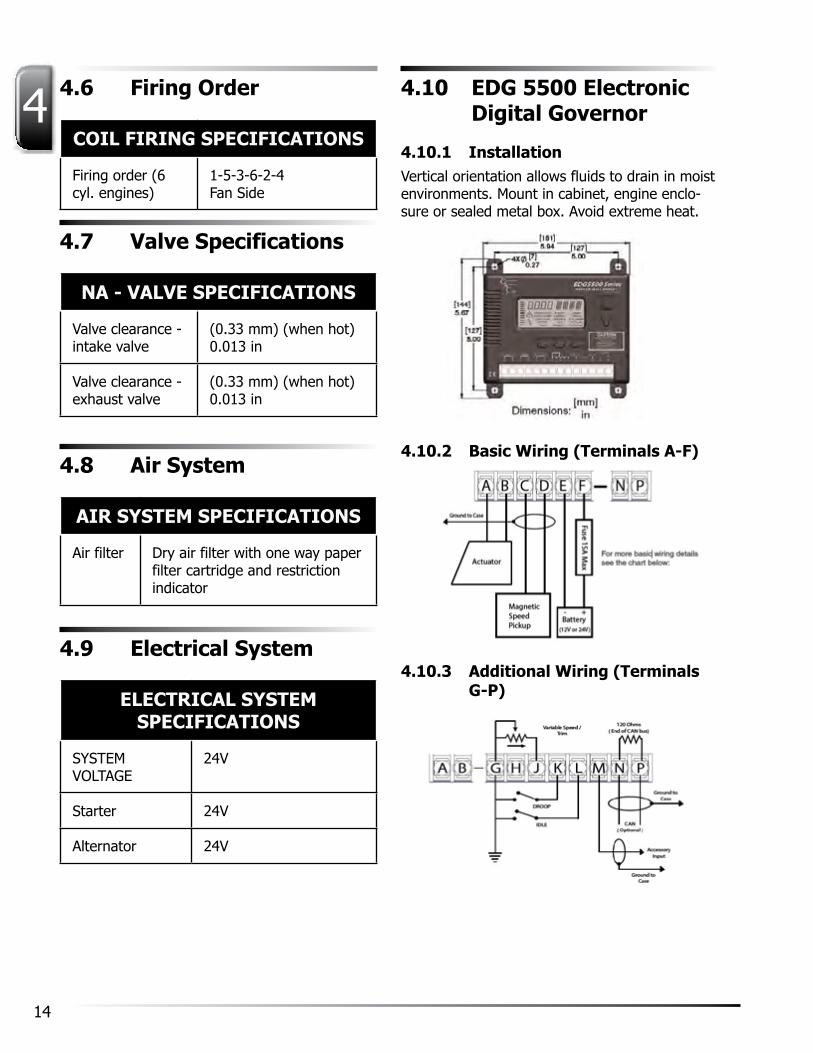
4 4.6 Firing Order
COIL FIRING SPECIFICATIONS
Firing order (6 cyl. engines)
1-5-3-6-2-4 Fan Side
4.7 Valve Specifications
NA - VALVE SPECIFICATIONS
Valve clearance - intake valve
(0.33 mm) (when hot) 0.013 in
Valve clearance - exhaust valve
(0.33 mm) (when hot) 0.013 in
4.8 Air System
AIR SYSTEM SPECIFICATIONS
Air filter Dry air filter with one way paper filter cartridge and restriction indicator
4.9 Electrical System
ELECTRICAL SYSTEM SPECIFICATIONS
SySTEMVOLTAGE
24V
Starter 24V
Alternator 24V
4.10 EDG 5500 Electronic Digital Governor
4.10.1 InstallationVertical orientation allows fluids to drain in moist environments. Mount in cabinet, engine enclo-sure or sealed metal box. Avoid extreme heat.
4.10.2 Basic Wiring (Terminals A-F)
4.10.3 Additional Wiring (Terminals G-P)

15(800) 331-3662www.ArrowEngine.com
44.10.4 Display and ControlsNumerical Area - Displays the value of a selected parameter or live running parameter.
Alpha-Numerical Area - Displays the units for the parameter (e.g. RPM)
Overspeed - Will blink when the unit is over-speed (Cycle power to restart)
4.10.5 ParametersThe following parameters must be set before starting the engine:
NOTE: To change parameters, refer to Section 4.10.4 Displays and Controls.
NOTE: The engine will maintain current op-eration while adjusting parameters. (i.e. NO
CHANGES) Since the scaling will be made to the Gain, Stability, and Derivative parameters auto-matically, go back and readjust these parameters to the desired levels.
CAUTION: Multiplier changes can make drastic changes. Changing a multiplier (e.g. GMUL) will affect the corresponding Quikset parameter (e.g. GAIN) in two ways:
1. If the multiplier is decreased by 1, corre-sponding Quikset value will double.
2. If the multiplier is increased by 1, the cor-responding Quikset value will halve.

16
4
4.10.6 TroubleshootingSystem Inoperative:
If the engine governing system does not func-tion, the fault may be determined by performing the voltage tests described in Steps 1 through 3. Positive (+) and negative (-) refer to meter polarity. Should normal values be indicated dur-ing troubleshooting steps, then the fault may be with the actuator or the wiring to the actuator. Tests are performed with battery power on and the engine off, except where noted. See actuator publication for testing procedure on the actuator.
Instability:
If unsuccessful in solving instability, contact GAC for assistance. [email protected] or (413) 233-1888.
Unsatisfactory Performance:

17(800) 331-3662www.ArrowEngine.com
44.10.7 Specifications
4.11 ESD5100 Series Speed Control Unit Specifications
4.11.1 IntroductionThe ESD5100 Series speed control unit is an all electronic device designed to control engine speed with fast and precise response to tran-sient load changes. This closed loop control, when connected to a proportional electric actua-tor and supplied with a magnetic speed sensor signal, will control a wide variety of engines in an isochronous or droop mode. It is designed for high reliability and built to withstand the engine environment.
Simplicity of installation and adjustment was foremost in the design. Non-interacting perfor-
mance controls allow near optimum response to be easily obtained.
Other features include; adjustable droop and idle operation, inputs for accessories used in multi-engine or special applications, protection against reverse battery voltage, transient voltages, accidental short circuit of the actuator and fail-safe design in the event of loss of speed sensor signal or battery supply.
4.11.2 DescriptionEngine speed information for the speed control unit is usually received from a magnetic speed sensor. Any other signal generating device may be used provided the generated frequency is proportional to engine speed and meets the volt-age input and frequency range specification. The speed sensor is typically mounted in close prox-imity to an engine driven ferrous gear, usually the engine ring gear. As the teeth of the gear pass the magnetic sensor, a signal is generated which is proportional to engine speed.
Signal strength must be within the range of the input amplifier. An amplitude of 0.5 to 120 volts RMS is required to allow the unit to function within its design specifications. The speed signal is applied to Terminals C and D of the speed control unit. Between these terminals there is an input impedance of over 33,000 ohms. Terminal D is internally connected to Terminal E, bat-tery negative. Only one end of the cable Shield should be connected.
When a speed sensor signal is received by the controller, the signal is amplified and shaped by an internal circuit to provide an analog speed signal. If the speed sensor monitor does not detect a speed sensor signal, the output circuit of the speed control unit will turn off all current to the actuator.
A circuit receives the speed sensor signal along with the speed adjust set point input. The speed range has a ratio of 8:1 and is adjusted with a 25 turn potentiometer. The output from the circuit is the input to the dynamic control section of the speed control unit. The dynamic control circuit, of which the gain and stability adjust-ments are part, has a control function that will provide isochronous and stable performance for most engine types and fuel systems.

18
4The speed control unit output circuit is influ-enced by the gain and stability performance adjustments. The governor system sensitivity is increased with clockwise rotation of the gain adjustment. The gain adjustment has a range of 33:1. The stability adjustment, when advanced clockwise, Increases the time rate of response of the governor system to match the various time constants of a wide variety of engines. The speed control unit is a PID device, the “D”, derivative portion can be varied when required (See Instability of Accessory Troubleshooting section).
During engine cranking , the actuator becomes fully energized and moves to the maximum fuel position, The actuator will remain in that state during engine cranking and acceleration. While the engine is at steady load. The actuator will be energized with sufficient current to maintain the governor speed set point.
The output circuit provides switching current at a frequency of about 500 Hz to drive the actuator. Since the switching frequency is well beyond the natural frequency of the actuator, there is no visible motion of the actuator output shaft. Switching the output transistors reduces its internal power dissipation for efficient power control. The output circuit can provide current of up to 10 amps continuous at 25°C for 12 and 24 VDC battery systems. The actuator responds to the average current to position the engine fuel control lever.
In standard operation, the speed control unit performance is isochronous. Droop governing can be selected by connecting terminals K and L and the percent of droop governing can be varied with the droop adjustment control. The droop range can be increased by connecting Terminals G and H.
The speed control unit has several performance and protection features which enhance the governor system. A speed anticipation circuit minimizes speed overshoot on engine start-up or when large increments of load are applied to the engine. Engine idle speed can be remotely selected and is adjustable. Accessory inputs to achieve variable speed operation and multi-engine control can be accepted by the ESD5100 Series speed control unit from GAC load sharing
modules, automatic synchronizers, ramp genera-tors and other accessory engine control mod-ules. Protection against reverse battery voltage and transient voltages is provided. The design is fail-safe in the event of loss of speed sensor signal or battery supply.

19(800) 331-3662www.ArrowEngine.com
4ESD SPEED CONTROL SPECIFICATIONS
Performance Isochronous Operation ±0.25 % or better
Speed Range /Governor 1K - 7.5K Hz Continuous
Speed Drift with Temperature ±0.5% Typical
Idle Adjust CW Min. 1200 Hz Below set speed
Idle Adjust CCW Min. 4100 Hz Below set speed
Droop Range 1 - 5% Regulation*
Droop Adj. Max. (K-L Jumpered) 875 Hz, 75 Hz per 1.0 A change
Droop Adj. Min. (K-L Jumpered) 15 Hz, 6 Hz per 1.0 A change
Speed Trim Range ±200 Hz
Remote Variable Speed Range 500 - 3.7 kHz
Terminal Sensitivity
J -115 Hz, ±15 Hz/Volt @ 5 K Impedance
L -735 Hz, ±60 Hz/Volt @ 65 K Impedance
N -148 Hz, ±10 Hz/Volt @ 1 M Impedance
P 10 VDC Supply @ 20 ma Max
Physical Dimensions See DIAGRAM 2
Weight 1.2 lb. (0.545 kg)
Mounting Any Position, vertical pre-ferred
Reliability Vibration 1G, 20-100 Hz
Testing 100% Functionally Tested

20
4ESD SPEED CONTROL SPECIFICATIONS
Environmental Ambient Operating Temperature Range
-40° to +185°F (-40° to +85°C)
Relative Humidity up to 95%
All Surface Finishes Fungus proof and corrosion resistance
Input Power DC Supply 24 ± 20% VDC Battery Systems**(Transient and Reverse Voltage Protected)
DC Supply Type Negative Ground (case isolated)
Power Consumption 100 MA (No actuator current)
Speed Signal Range 0.5 – 50 VAC
Actuator Current Range @ 77°F (25°C)
10 Amps continuous***
21(800) 331-3662www.ArrowEngine.com
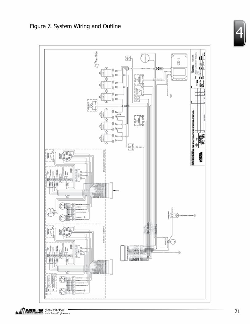
4Figure 7. System Wiring and Outline

22
44.11.3 InstallationThe ESD5100 Series speed control unit is rug-ged enough to be placed in a control cabinet or engine mounted enclosure with other dedicated control equipment. If water, mist, or condensa-tion may come in contact with the controller, it should be mounted vertically. This will allow the fluid to drain away from the speed control unit. Extreme heat should be avoided.
WARNINGAn overspeed shutdown device, independent of the governor system, should be provided to prevent loss of engine control, which may cause personal injury or equipment damage. DO NOT rely exclusively on the governor system electric actuator to prevent over-speed. A secondary shut off device, such as a fuel solenoid, must be used.
WiringBasic electrical connections are illustrated in Figure 3.1. Actuator and battery connections to Terminals A, B, E, and F should be #16 AWG (1.3 mm sq.) or larger. Long cables require an increased wire size to minimize voltage drops.
The battery positive (+) input, Terminal F, should be fused for 15 amps as illustrated. The ESD5100 series is suitable for 12 VDC and 24 VDC operation.
Magnetic speed sensor wires connected to Terminals C and D MUST BE TWISTED AND/OR SHIELDED for their entire length. The speed sensor cable shield should ideally be connected as shown in Diagram 2. The shield should be insulated to insure no other part of the shield comes in contact with engine ground, otherwise stray speed signals may be introduced into the speed control unit. With the engine stopped, adjust the gap between the magnetic speed sensor and the ring gear teeth. The gap should not be any smaller than 0.020 in. (0.45 mm). Usually, backing out the speed sensor 3/4 turn after touching the ring gear teeth will achieve a satisfactory air gap. The magnetic speed sen-sor voltage should be at least 1 VAC RMS during cranking.
AdjustmentsBefore Starting EngineCheck to insure the GAIN and STABILITy adjust-ments, and if applied, the external SPEED TRIM CONTROL are set to mid position.
Start EngineThe speed control unit governed speed setting is factory set at approximately engine idle speed. (1000 Hz, speed sensor signal)
Crank the engine with DC power applied to the governor system. The actuator will energize to the maximum fuel position until the engine starts. The governor system should control the engine at a low idle speed. If the engine is unstable after starting, turn the GAIN and STA-BILITy adjustments counterclockwise until the engine is stable.
Governor Speed SettingThe governed speed set point is increased by clockwise rotation of the SPEED adjustment pot. Remote speed adjustment can be obtained with an optional 5K Speed Trim Control. (See Figure 3.1)
Governor PerformanceOnce the engine is at operating speed and at no load, the following governor performance adjust-ment can be made.
1. Rotate the GAIN adjustment clockwise until instability develops. Gradually move the adjustment counterclockwise until stability returns. Move the adjustment one division further counterclockwise to insure stable performance (270° pot).
2. Rotate the STABILITy adjustment clockwise until instability develops. Gradually move the adjustment counterclockwise until stability returns. Move the adjustment one division further to insure stable performance (270° pot).
3. Gain and stability adjustments may require minor changes after engine load is applied. Normally, adjustments made at no load achieve satisfactory performance. A strip chart recorder can be used to further opti-mize the adjustments.

23(800) 331-3662www.ArrowEngine.com
4If instability cannot be corrected or further performance improvements are required, refer to the SySTEM TROUBLESHOOTING section. In this section, information can be found regarding troubleshooting procedures as well as instruc-tions on adjusting the DIP switch positions of the ESD5131.
Idle Speed SettingAfter the governor speed setting has been adjusted, place the optional external selector switch in the IDLE position. The idle speed set point is increased by clockwise rotation of the IDLE adjustment control. When the engine is at idle speed, the speed control unit applies droop to the governor system to insure stable opera-tion.
Speed Droop OperationDroop is typically used for the paralleling of en-gine driven generators.
Place the optional external selector switch in the DROOP position. DROOP is increased by clock-wise rotation of the DROOP adjustment control. When in droop operation, the engine speed will decrease as engine load increases. The percent-age of droop is based on the actuator current change from engine no load to full load. A wide range droop is available with the internal control. Droop level requirements above 10% are un-usual.
If droop levels experienced are higher or lower then these required, contact GAC for assistance.
After the droop level has been adjusted, the rated engine speed setting may need to be reset. Check the engine speed and adjust that speed setting accordingly.
Accessory InputThe Auxiliary Terminal N accepts input signals from load sharing units, auto synchronizers, and other governor system accessories, GAC acces-sories are directly connected to this terminal. It is recommended that this connection from accessories be shielded, as it is a sensitive input terminal.
If the auto synchronizer is used alone, not in conjunction with a load-sharing module, a 3 M ohm resistor should be connected between
Terminals N and P. This is required to match the voltage levels between the speed control unit and the synchronizer.
When an accessory is connected to Terminal N, the speed will decrease and the speed adjust-ment must be reset. When operating in the upper end of the control unit frequency range, a jumper wire or frequency trim control may be required between Terminals G and J. This in-creases the frequency range of the speed control to over 7000 Hz
Accessory SupplyThe +10 volt regulated supply, Terminal P, can be utilized to provide power to GAC governor system accessories. Up to 20 ma of current can be drawn from this supply. Ground reference is Terminal G.
Wide Range Remote Variable Speed OperationSimple and effective remote variable speed can be obtained with the ESD5100 Series speed control unit.
A single remote speed adjustment potentiometer can be used to adjust the engine speed continu-ously over a specific speed range. Select the desired speed range and corresponding poten-tiometer value. (Refer to the TABLE below.) If the exact range cannot be found, select the next higher range potentiometer. An additional fixed resistor may be placed across the potentiometer to obtain the exact desired range. Connect the speed range potentiometer.
To maintain engine stability at the minimum speed setting, a small amount of droop can be added using the DROOP adjustment. At the maximum speed setting the governor perfor-mance will be near isochronous, regardless of the droop adjustment setting.

24
4VARIABLE RANGE
POTENTIOMETER VALUE
SPEED RANGE POTENTIOMETER VALUE
900 Hz 1K
2,400 Hz 5K
3,000 Hz 10K
3,500 Hz 25K
3,700 Hz 50K
Hz to RPM
HZx60 = RPM# Teeth

25(800) 331-3662www.ArrowEngine.com
4
5
26
2. If an external air intake is required, it must be suitably designed to supply intake air of the proper temperature range. High intake air temperature results in power loss while lower intake air may hinder starting of auto-matic standby units. An external air source must also prevent the intake of exhaust gas from other equipment, flammable vapor, and entry of rain and water.
3. All intake ducting must be airtight to avoid entry of unfiltered air.
4. Restricted intake systems must be avoided. Sharp or numerous bends and undersized ducting will decrease the available air flow to the engine.
5. Engine heat radiation will affect air tempera-tures in the enclosed installations. Ventilation systems may be required.
5.3 Flywheel, Housing Runout, & Crankshaft Endplay
Even with the best maintenance, an engine can encounter trouble if such things as proper mounting, alignment with other equipment, flywheel and housing run out and sufficient crankshaft endplay are disregarded in the initial installation or in subsequent relocations of the engine. Although flywheel and housing run out and crankshaft endplay are firmly established within limits at the factory, such things as rough handling or improper installation of power take-offs or clutches may adversely affect these clear-ances and lead to serious engine damage. These items should be checked prior to operation.
A major factor in obtaining long service life from any engine and clutch or power takeoff assembly is the proper alignment of the flywheel housing, flywheel and pilot bearing bore. Distortion or lack of a common center on either of these parts will set up forces sure to be destructive to bear-ings, crankshaft, clutch and the driven equip-
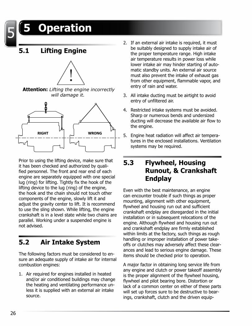
5.1 Lifting Engine
Attention: Lifting the engine incorrectly will damage it.
RIGHT WRONG
Prior to using the lifting device, make sure that it has been checked and authorized by quali-fied personnel. The front and rear end of each engine are separately equipped with one special lug (ring) for lifting. Tightly fix the hook of the lifting device to the lug (ring) of the engine, the hook and the chain should not touch other components of the engine, slowly lift it and adjust the gravity center to lift. It is recommend to use the sling shown. While lifting, the engine crankshaft is in a level state while two chains are parallel. Working under a suspended engine is not advised.
5.2 Air Intake System
The following factors must be considered to en-sure an adequate supply of intake air for internal combustion engines:
1. Air required for engines installed in heated and/or air conditioned buildings may change the heating and ventilating performance un-less it is supplied with an external air intake source.
5 Operation
5
27(800) 331-3662www.ArrowEngine.com
ment. In addition, because of normal manufac-turing tolerances, when an engine is installed in a mounting formerly occupied by another en-gine, it is not safe to assume that the drive shaft of the power take off will automatically line up with a coupling located for the previous engine. In such circumstances, either the engine mounts must be shimmed or adjusted or the driven mechanism must be relocated and adjusted a few thousandths to bring the engine drive line from crankshaft bearing to driven shaft coupling into good alignment.
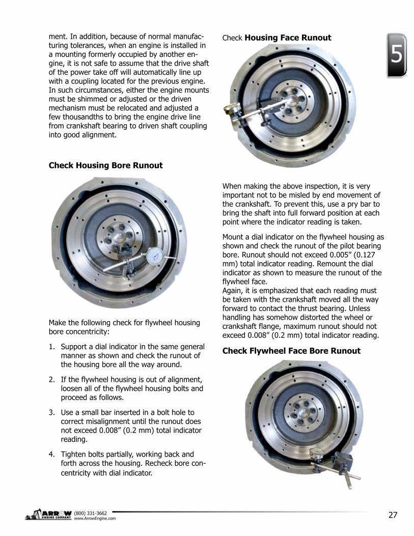
Check Housing Bore Runout
Make the following check for flywheel housing bore concentricity:
1. Support a dial indicator in the same general manner as shown and check the runout of the housing bore all the way around.
2. If the flywheel housing is out of alignment, loosen all of the flywheel housing bolts and proceed as follows.
3. Use a small bar inserted in a bolt hole to correct misalignment until the runout does not exceed 0.008” (0.2 mm) total indicator reading.
4. Tighten bolts partially, working back and forth across the housing. Recheck bore con-centricity with dial indicator.
Check Housing Face Runout
When making the above inspection, it is very important not to be misled by end movement of the crankshaft. To prevent this, use a pry bar to bring the shaft into full forward position at each point where the indicator reading is taken.
Mount a dial indicator on the flywheel housing as shown and check the runout of the pilot bearing bore. Runout should not exceed 0.005” (0.127 mm) total indicator reading. Remount the dial indicator as shown to measure the runout of the flywheel face. Again, it is emphasized that each reading must be taken with the crankshaft moved all the way forward to contact the thrust bearing. Unless handling has somehow distorted the wheel or crankshaft flange, maximum runout should not exceed 0.008” (0.2 mm) total indicator reading.
Check Flywheel Face Bore Runout

5
28
Measure crankshaft endplay with a dial indica-tor mounted on the crankcase. Use a small pinch bar to move the crankshaft fully forward. Set the indicator at zero and use the bar to thrust the shaft to fully rearward. Check endplay reading on dial indicator with the tolerance given in the specifications.
Check Pilot Bearing Bore Runout
CAUTIONThe importance of correct crankshaft endplay cannot be overstressed. Operation of an en-gine having insufficient or excessive crankshaft endplay can result in serious damage. Insuffi-cient clearance will prevent proper lubrication of the thrust surfaces causing the main bearings to overheat and lock on the shaft.
5.4 Before Starting
The engine should not be started until it is properly installed in its final position. Check for free rotation. If the engine has not been rotated for some time, oil it through the spark plug openings and check for rotation by hand before attempting to start the engine. Any resistance to free cranking should be thoroughly checked out. Rust and corrosion can cause the engine to seize. Check the connections for proper battery polarity.
5.4.1 Filling Engine with OilThe oil must be of the proper weight and clean. See section the Lubrication Guide section.
1. Make sure the oil drain plug is installed and properly tightened.
2. Open the oil cap and fill the case with oil until the oil reaches the full level on the dipstick.
3. Replace the oil filler cap.
Always check oil level before starting the engine.
5.4.2 Filling Cooling FluidThe cooling fluid is a mix of clean deionized wa-ter and antifreeze. Please follow the antifreeze manufacturers recommended process and quan-tities. Coolant capacity is 33 gallons.
NOTEFrequently adding or changing water might result in encrustation. Leaking of the cooling system should be repaired as soon as possible. Add clean deionized water if at all possible and avoid changing the cooling fluid if possible. Fill the cooling fluid into the water inlet of the radiator or heat exchanger and discharge the air of the cooling system. The cooling fluid level must be checked every time the engine is started.
5.4.3 Attaching Gas LineWhen starting the engine for the first time, purge air from the gas line. This will clear air and any foreign matter from the gas line and provide fuel to start immediately.
CAUTIONNatural gas is highly explosive.
5.5 Startup
Before Starting1. Be sure the main clutch, circuit breaker, or
other power transmission devices are disen-gaged or turned off.

5
29(800) 331-3662www.ArrowEngine.com
2. Trace through the external cooling system to make sure all control valves are properly opened and the drain cocks closed. Check the coolant level.
3. Inspect drive belts, water pump, alterna-tor, and other equipment. Examine for good condition and correct tension.
4. Make certain all guards are secure on engine and driven equipment.
5. Check the air restriction indicator, if engine is equipped with this. Clean or replace air filter element and dust cap if indicator shows red.
6. Check the oil level as indicated on the oil dipstick prior to starting engine. Stop engine and recheck oil level after 5 to 10 minutes of operation at low idle. Add oil as required to bring level to full mark.
7. If the engine has been standing idle for some time, bar it over by hand to be sure it is free.
5.5.1 Quick Trouble Check Chart
Check Controls
Follow starting steps, re-set safety controls. Remote or automatic operation engines have special pro-cedures.
Check Fuel System
Be sure fuel is getting to the engine. Check to ensure that the valves are open. Check the possibility of water, rust or pipe scale.
Check the Cooling System
Check the coolant level and ensure that the sys-tem is not air locked. Check that the radiator is not blocked.
Check the Intake/Exhaust System for Blockages
Check to see if the air filter is dirty and check the air restriction indicator. Make sure the air intake or ex-haust outlet is not capped.
Check Ignition See if there is water on the ignition parts and wires. Check for signs of corro-sion at the wire terminals or for broken wires. Check to see if the spark plugs are properly gapped. Check ignition pickup sys-tem for proper operation.
If these checks do not solve the problem, refer to the troubleshooting section.
5.6 Manual Oil Priming Pump
The priming function of the A-160 manual pump is as follows:
1) Neutral position: the oil outlet is closed. When the hand oil pump is not used, the switch should be in the neutral position.
2) Pre-lubrication position: before starting the engine, put the switch in the pre-lubrica-tion position and move the handle to pre-lubricate the engine bearings. Remove the air inside the oil pump to start rapid lubrica-tion after engine startup. This operation will reduce friction, extend the service life of the engine, and promote smoother start up.
3) Drain position: removes oil from the oil pan and discharges it out of the engine. It is used to remove the oil from the oil pan.

5
30
Ordinarily, an exercise run of 1.5 hours will be needed to stabilize temperatures. If the engine cannot be loaded it should not be exercised for more than 10 minutes each exercise period.
Some types of driven equipment cannot be operated without fairly extensive procedures to put them on line. Examples are hospital genera-tors in some types of switching configurations, air conditioning compressors which can only be loaded by changing over to chilled water from heating water circulation, and pumps which are not set up for waste discharge or recirculation. In such cases, weekly exercise periods may have to be reduced, where possible, to operational periods long enough only to prove the engines ability to crank and start or checkout of starting circuitry and safety equipment with the starter disabled. In this event, special attention must be taken to prevent internal corrosion, sticking and gumming of fuel controls and deteriorated start-ing batteries. In all cases, arrangements should be made to run the engine and driven equip-ment under load at least every 90 days.
5.6.3 Light Load OperationWe recommend the following maintenance sched-ule for A-160 engines that are consistently run at 25% or less of the continuous duty rating. This schedule is to be followed in addition to standard maintenance procedures.
Maintain engine jacket coolant temperature be-tween 160°F and 190°F (82.25°C - 87.75°C)
Air cleaner elements should be checked periodi-cally, and cleaned and replaced as required.
At 50 hours of operation, run engine at 50% load or more to clean carbon off valves and pistons.
Inspection and overhaul schedule of cylinder heads should be updated to allow for a 25% reduction in hours between servicing.
Change lube oil every 750 hours.
Figure 8. Oil Priming Pump
5.6.1 Break-In ProcedureNew or overhauled engines should receive a break-in run. After a warm up of approximately 30 minutes, proceed with a load and unload cycle, repeating loading (minimum of a half load, maximum full load) with equal idle periods in 5 minute intervals for a period of two hours. This results in a rapid break-in and quick seating of piston rings. Never idle for more than 15 minutes during the break-in or for the first 100 hours of operation.
NOTEStandby generator engines should follow this procedure using a load bank.
5.6.2 Exercise of Standby UnitIt is recommended that a generator set or other standby units be exercised once each week. A record should be maintained of performance, in-cidental servicing, and output of both the engine and driven equipment.
Always operate the engine long enough to sta-bilize oil and water temperatures at the normal operating level expected under load. Do not operate under no-load conditions for longer than very brief periods. Loads of at least one third up to the normal rated capacity are recommended.
5.6.4 Engine Warm-upIt is important that the engine is warmed up properly. This will ensure the engine’s longev-ity. A warm up period allows for an even ther-mal expansion of engine components. Also, the

5
31(800) 331-3662www.ArrowEngine.com
lubricant warms up and attains normal viscosity during warm up. Oil pressure is also built up as-suring proper oil distribution and lubrication of vital engine parts.
NOTEStandby units that require immediate full load pickup can be equipped to maintain a constant engine temperature. Consult your Arrow distribu-tor for further information.
To warm the engine up, run the engine at me-dium engine speed with no load. Warm up the engine until oil pressure stabilizes and coolant temperature reaches at least 100°F - 120°F (37.78°C-48.89°C.)
CautionIf adequate oil pressure is not indicated within 25 to 30 seconds, shut the engine down at once and determine the cause. Never operate an engine without adequate oil pressure readings in the hope that a faulty gauge or cold oil is respon-sible. The problem could be something else and serious engine damage may result.
5.6.5 Governor Speed SettingThe Speed set point is increased by clockwise rotation of the “Speed” rotation pot.
Once the engine is at operating speed and at no load, the following governor performance adjust-ment may be made...
1. Rotate the “Gain” clockwise until instability develops. Gradually move the adjustment counterclockwise until stability returns. Move the adjustment one division further coun-terclockwise to insure stable performance (270°pot.)
2. Rotate the “Stability” clockwise until instabil-ity develops. Gradually move the adjustment counterclockwise until stability returns. Move the adjustment one division further coun-terclockwise to insure stable performance (270°pot.)
3. “Gain” and “Stability” adjustments may require minor changes after engine load is
applied. Normally, adjustments made with no load achieves satisfactory performance. A strip chart recorder can be used to further optimize the adjustments.
If instability cannot be corrected or further per-formance improvements are required, refer to the Troubleshooting section.
5.7 Stopping the Engine
Do not stop the engine from a full load. De-crease the speed before stopping the engine and let it idle for another 5 to 10 minutes. Shut the power off after the engine is stopped.
Any engine whose cooling system does not con-tain antifreeze must be drained after the engine is stopped to prevent the engine from being damaged in cold weather.

32
66.1 Engine Performance
Record
Engine operating information recorded during regular inspections is necessary to apply proper preventive maintenance schedules. Accurate re-cords help control costs by avoiding unnecessary servicing, ensuring needed servicing, and pro-viding trend information on the general engine condition. We recommend keeping a record of the following information, selecting items that apply to your engine:
• Hour Meter Reading
• Tachometer rpm
• Fuel Meter Reading
• Engine Oil Pressure
• Engine Oil Temp
• Coolant Temperature
• Gas Pressure at the Carburetor Intake
• Manifold Vacuum
• Crankcase Pressure pos/neg
• Unusual Noise(s) Or Vibration
• Oil Leaks
• Coolant Leaks
• Alternator Output
6.1.1 FuelsArrow A-160 gas engines are designed to burn natural gas. All power ratings are based on natural gas with a heat value of 900 BTU/cu. ft. (LHV)
Required fuel conditions:
1. 900 to 1100 BTU’s. Octane rating of at least 85.
2. Maximum liquid fuel hydrocarbons at the coldest expected engine mounted regula-
tor fuel outlet temperature is 2% or less by gaseous volume.
3. Maximum total organic halide content (TOX), expressed as chlorine concentration, is 60 micrograms/liter.
4. Maximum permissible free hydrogen is 12% by volume.
5. Maximum solid particle size is 5 microns.
6. No liquid water is permitted at the outlet of the engine mounted fuel regulator at the coldest expected temperature.
6.2 Maintenance Procedures
6.2.1 Air FilterAn air restriction indicator device mounted in the piping from the circular style air filter serves as positive evidence when air filter service is neces-sary.
CAUTIONUnless the signal is locked in view indicating a clogged air cleaner, it will return to a normal set-ting upon engine shut down. Normally the ele-ment is serviced long before the gauge indicates a need, but the operator is cautioned to check the gauge every day while the engine is run-ning. After the element has been serviced, the reset button on the restriction indicator should be depressed to reset it.
The A-160 engines use a circular style air clean-er. This style cleaner has a pre-cleaner built into each assembly. Dirt trapped by this pre-cleaner will be collected in a dust cup on the end of the filter.
6.2.2 Check Connection BoltCheck the bolts of the engine, generator and intake/exhaust manifold and the connections of bolts and hoses and retighten them if necessary.
6 Maintenance

33(800) 331-3662www.ArrowEngine.com
66.2.3 Check Belts and Tensionersyour A-160 is equipped with automatic tension-ers. These require no maintenance as long as they are in good operating condition.
6.2.4 Cooling SystemThe cooling water of the engine must be deion-ized water mixed with antifreeze.
Should your A-160 coolant need to be drained, there are three major drain points,
1. The radiator (drain fitting on the bottom).
2. Exhaust manifold (left side of the engine to the rear).
3. Oil cooler (right hand side of the engine, midway to the front).
4. Drain or hot water outlet (right hand side of the engine, towards the front).
5. Drain or hot water outlet (right hand side near flywheel housing).
6.2.5 AntifreezeThe cooling system of the engine holds about 33 gallons without provision for other equipment. When adding antifreeze compounds on a per-centage basis, remember to include the coolant volume of the radiator and other external parts of the cooling system.
Please refer to the antifreeze manufacturers instructions for the mixing ratio.
The concentration of the antifreeze should be checked once every 1,000 hours or once every season. The antifreeze should be changed every two years to avoid corrosion.
6.2.6 ThermostatUnder normal conditions the heat sensitive thermostats in the water outlet will maintain temperatures within the desired limits. The steps necessary to accomplish this are simply the re-moval of the water outlet connection hose, and the cap screws securing the housing. Thermo-
34
6stats damaged by corrosion or other causes are not repairable and must be replaced.
6.2.7 Cleaning the Cooling SystemWhen the proper inhibitors or antifreeze solu-tions are used, radiator and cooling passage accumulations will not be excessive. About once each year, however, the engine will benefit if the cooling system is cleaned of sludge and sedi-ment. A number of excellent commercial cooling system cleaners are available. ARROW ENGINE COMPANy SUGGESTS THAT AN OPERATOR CONSIDERING THE USE OF SUCH A CLEANER FIRST INVESTIGATE ITS POSSIBLE REACTION WITH THE COPPER AND BRONZE COMPONENTS IN THE ENGINE. If such a cleaner is used, follow the manufacturers recommendations carefully.
NOTEMulti-viscosity oils, 10W30 for example, should be used only when cold starting conditions make it absolutely necessary. Oil change periods should be reduced by 50% for engines using multi-viscosity oil because multi-viscosity oils may rapidly lose their highest viscosity rating in industrial service.
6.2.8 Oil ConsumptionOil consumption should range from 0.0005 to 0.004 pounds per horsepower hour as deter-mined by the following formula:
LBS HP HR= 1.82 x Quarts of oil used Operating HP x total hours of operation
6.2.9 Oil ChangesThe oil level and condition should be checked prior to starting the engine each time. Replace oil at any time it appears diluted, broken down, thickened by sludge, or otherwise deteriorated. Remember that some modern oils cannot be judged on the basis of color alone because the additives are intended to hold carbon particles in suspension. The standard filters supplied will not remove these particles. The dark appearance of the oil is not necessarily an indication that the oil should be changed.
Whenever oil is changed the filters must also be serviced. Oil performance will be affected by engine load, temperature, fuel quality, atmo-spheric dirt, moisture and maintenance. Where
oil performance problems arise or are anticipated, the oil supplier should be consulted.
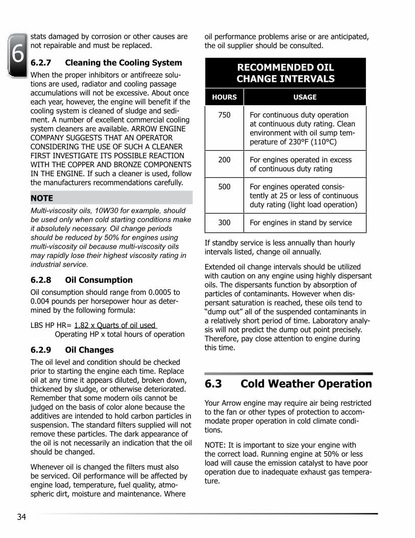
RECOMMENDED OIL CHANGE INTERVALS
HOURS USAGE
750 For continuous duty operation at continuous duty rating. Clean environment with oil sump tem-perature of 230°F (110°C)
200 For engines operated in excess of continuous duty rating
500 For engines operated consis-tently at 25 or less of continuous duty rating (light load operation)
300 For engines in stand by service
If standby service is less annually than hourly intervals listed, change oil annually.
Extended oil change intervals should be utilized with caution on any engine using highly dispersant oils. The dispersants function by absorption of particles of contaminants. However when dis-persant saturation is reached, these oils tend to “dump out” all of the suspended contaminants in a relatively short period of time. Laboratory analy-sis will not predict the dump out point precisely. Therefore, pay close attention to engine during this time.
6.3 Cold Weather Operation
your Arrow engine may require air being restricted to the fan or other types of protection to accom-modate proper operation in cold climate condi-tions.
NOTE: It is important to size your engine with the correct load. Running engine at 50% or less load will cause the emission catalyst to have poor operation due to inadequate exhaust gas tempera-ture.

35(800) 331-3662www.ArrowEngine.com
6Oil Change Procedure
1. Start the engine and run until reaching oper-ating temperature.
2. Locate Oil Pump on right side of engine.
3. Place selector valve in Drain position.
4. Connect one end of the drain hose to outlet pipe of pump and the other to an oil bucket.
5. Pump oil out. (Refer to section 5.6).
6. Replace the oil filter elements.
a. Remove the oil filters
b. Apply oil on the filter seal rings and tighten the new filter element by hand.
7. Fill with clean oil up to the full mark on the dipstick.
8. Operate the engine for a few minutes in order to circulate the oil throughout the sys-tem. Check the tightness of the new oil filter element while the engine is running.
9. Stop the engine and check to see if any ad-ditional oil is required. Bring the oil level to the “full” mark.
Not all oils in every type of engine will give maxi-mum service. Therefore be careful to examine the oil after the first draining to determine whether it is standing up in service. Trial peri-ods of 10 hours are suggested. At the end of such periods make a careful inspection of the oil depth gauge for sludge, frothing and emulsi-fication. Such conditions call for more frequent changes or a different oil. In cold weather operation, low oil temperatures - below 160°F (71.1°C) - are particularly likely to cause sludge formation. Temperature control devices such as curtains or shutters should be used if needed in order to hold the oil temperature around 180°F (82.2°C).
6.3.1 Oil FiltersFull flow filters are an integral part of the lubri-cation system. Never block off the filter even temporarily when running the engine. ALL OIL
GOING TO THE ENGINE MUST PASS THROUGH THE FILTER. For this reason it is very important when changing oil that the element be changed and the filter parts thoroughly washed to pre-vent clogging or blocking of the oil flow to the engine. At the same time, the by pass valve should be examined for proper operation. To ensure a clean job without leaks it is important that the filter seal gasket be handled carefully and replaced at the same time as the element.
6.3.2 Centrifuge Oil FilterThe Centrifuge oil filter cleans your engine con-tinuously when your engine is running. It sepa-rates dirt below 1 micron from engine oil thus lowering the wear rate of engine components drastically. It avoids harmful oil degradation and arrests depletion of oil additives increasing the oil life. The Centrifuge cleaner does not require any spare parts to be replaced and gives consis-tent performance throughout engine life.

36
6Cover Bolt
Centrifuge Cover
Rotor Cover
Rubber Seal
CENTRIFUGE OIL FILTER
6.3.3 Cleaning frequency:For consistent performance, the centrifuge rotor needs to be cleaned periodically. It is recommend-ed that you service the centrifuge filter at every oil change period. The volume of dirt collected depends upon engine application, loading and en-vironment in which engine is working. Exact time of servicing the centrifuge can vary depending on your oil change periods. Please follow the instruc-tions below for cleaning the centrifuge filter.
6.3.4 Identification and LocationThe Centrifuge is located on the same manifold on which full flow oil filter is mounted. The centrifuge can be easily identified with a dome shaped cover bearing instruction sticker. The exact location is as shown in this photograph.
6.3.5 Servicing Instructions:• It is a precision assembly, handle with care.
• Carry out servicing preferably when the en-gine oil is still warm.
• All threaded parts in this centrifuge assembly have right hand threads.
• Servicing of the centrifuge require following tools: 13 mm wrench, a blunt knife, small adjustable pliers, and waste rags for clean-ing.
6.3.6 Servicing Procedure:1. Unscrew top nut with a 17 mm wrench and
remove centrifuge cover. The centrifuge cover nut has a puller arrangement so that the cover will be lifted as you unscrew the nut.
2. Hold the rotor in hand and lift to remove it completely from central shaft. The rotor will contain about 7 oz. of oil, drain oil from ro-tor. The rotor has two bushings at its ends. Take care while removing rotor from central shaft. The rotor should not fall; otherwise it will damage the bushings.

37(800) 331-3662www.ArrowEngine.com
6
3. Remove rotor assembly by holding rotor assembly in hand. Discard and replace the whole assembly.
4. After you open the rotor, you will see cake formed sticky dirt mass all around the rotor cover from inside. Remove the dirt by a blunt knife. Clean the rotor cover and all rotors thoroughly. Be sure to clean the centrifuge center shaft.
5.
6. Assemble rotor in correct sequence of parts. Match arrow marks on rotor cover and ro-tor. Tighten nut firmly by hand. Install ro-tor on shaft and assemble cleaner cover.
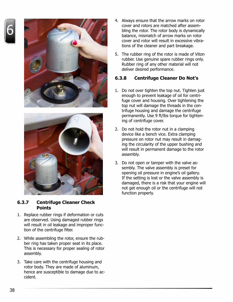
38
6
6.3.7 Centrifuge Cleaner Check Points
1. Replace rubber rings if deformation or cuts are observed. Using damaged rubber rings will result in oil leakage and improper func-tion of the centrifuge filter.
2. While assembling the rotor, ensure the rub-ber ring has taken proper seat in its place. This is necessary for proper sealing of rotor assembly.
3. Take care with the centrifuge housing and rotor body. They are made of aluminum, hence are susceptible to damage due to ac-cident.
4. Always ensure that the arrow marks on rotor cover and rotors are matched after assem-bling the rotor. The rotor body is dynamically balance, mismatch of arrow marks on rotor cover and rotor will result in excessive vibra-tions of the cleaner and part breakage.
5. The rubber ring of the rotor is made of Viton rubber. Use genuine spare rubber rings only. Rubber ring of any other material will not deliver desired performance.
6.3.8 Centrifuge Cleaner Do Not’s
1. Do not over tighten the top nut. Tighten just enough to prevent leakage of oil for centri-fuge cover and housing. Over tightening the top nut will damage the threads in the cen-trifuge housing and damage the centrifuge permanently. Use 9 ft/lbs torque for tighten-ing of centrifuge cover.
2. Do not hold the rotor nut in a clamping device like a bench vice. Extra clamping pressure on rotor nut may result in damag-ing the circularity of the upper bushing and will result in permanent damage to the rotor assembly.
3. Do not open or tamper with the valve as-sembly. The valve assembly is preset for opening oil pressure in engine’s oil gallery. If the setting is lost or the valve assembly is damaged, there is a risk that your engine will not get enough oil or the centrifuge will not function properly.

39(800) 331-3662www.ArrowEngine.com
66.4 Troubleshooting Chart
PROBLEM PROBLEM CAUSE ACTION
1. Leakage through cleaner. Rectangular rubber ring damage.
Change rubber ring.
2. Rotor does not rotate. Nozzle block. Open rotor and clean nozzles thoroughly. Reas-semble the cleaner.
3. Rotor does not rotate even after cleaning noz-zles.
Entry valve blocked. Do not open entry valve assembly. It requires spe-cial tools. Contact company representative.
4. Rotor rotates but at low speed.
Leakage of oil through ro-tor assembly
Open rotor and ensure that the rubber ring has taken proper seat on rotor body. Then reassemble the rotor.
5. Rotor speed very low or even rotor does not rotate
Brushes damaged perma-nently.
Ensure that the rotor is free on shaft. Else replace entire rotor assembly.
6. Rotor rotates but at low speed
Rotor filled with dirt com-pletely.
Time for cleaning the rotor.
7. Abnormal vibrations of centrifuge cleaner.
Mismatch between arrow marks on rotor cover and rotor.
Open rotor and reassemble it properly.
8. Cleaner does not collect any dirt.
Rotor not rotating at de-sired speed.
See point no 2 & 3. Consult authorized representative.
6.5 Spark Plug Adjustments
Misfiring or erratic operation may be due to faulty spark plugs caused by carbon accumula-tions and burning of the electrodes. They should be cleaned, inspected and the gaps checked approximately every 250 hours of operation or more often if the engine idles for prolonged pe-riods. After 500 hours, it is advisable to replace the entire set when any spark plug is defective.
Deposits on the electrodes and insulator may be removed by commercial abrasive cleaners. Scraping the insulator is not recommended since the resulting scratches increase the tendency of carbon deposits to form.
After the spark plug has been cleaned, adjust the gap with a round wire gauging tool to 0.028” (0.711 mm) by bending the outer electrode. As the spark plugs will have a tendency to burn the electrodes and widen the gap, it is important that gap be checked whenever the plugs are removed from the engine. Missing at low speeds is very often due to a wide spark plug gap.

40
62. Rotate the GAIN adjustment clockwise until
instability develops. Gradually move the adjustment counterclockwise until stability returns. Move the adjustment one division further to insure stable performance (270° pot.)
3. Rotate the STABILITy adjustment clockwise until instability develops. Gradually move the adjustment counterclockwise until stability returns. Move the adjustment one division further to insure stable performance (270°
pot.) 4. GAIN and STABILITy adjustments may
require minor changes after engine load is applied. Normally, adjustments made at no load provide satisfactory performance. A strip chart recorder can be used to further opti-mize the adjustments.
If instability cannot be corrected or further performance improvements are required, please refer to Troubleshooting Section 10.6 Governing Systems.
6.7.1 Idle Speed SettingAfter the governor speed setting has been adjusted, place the optional external selector switch in the IDLE position. The idle speed set point is increased by the clockwise rotation of the IDLE adjustment control. When the engine is at idle speed, the speed control unit applied droop to the governor system to insure stable operation.
6.8 Integral Throttle Body Actuator
6.8.1 Idle AdjustmentAn adjustable Idle Stop setscrew is provided to set a fixed fuel opening, if desired. Using the appropriate Hex wrench, you must completely remove the first “locking” setscrew. This will give you access to the inner Idle Adjustment setscrew for adjustment using the same Hex wrench. Turning the wrench clockwise will increase the fixed throttle opening. Typically, the engine speed should be set by unplugging the actuator or by turning off the governor power once the
Examine for cracked porcelain, leakage, burned electrodes, deposits on center insulator, cor-rect gap, good washers and clean threads and seating surface. Remember a plug may appear satisfactory and still miss.
NOTEWhen replacing spark plugs, use new gaskets. Proper seating of the gasket is necessary for sealing the combustion chamber and transferring heat from the plug. Use spark plug tap to clean threads, allowing for proper heat transfer.
6.6 Adjusting the Carburetor
(Non emission equipped engines only.) To adjust the carburetors, take the following steps:
1. Open the gas regulating valve at the carbu-retor fuel inlet. With the dial cock open, the engine will hit and run.
2. With the engine at desired speed and load, adjust the dial cock so the engine runs the smoothest and easiest, with no knocking, deceleration, or fluctuation of speed.
3. Gradually close the fuel regulating valve at the carburetor inlet to a point where the en-gine just begins to fluctuate, opening it back up to where the engine just smooths out again. Then open the dial cock all the way.
4. Open the throttle all the way by hand to assure the engine will pick up load without hesitation or missing. If it does not, open the fuel regulating valve to a point where the engine will speed up smoothly. Proper fuel adjustments are important to insure efficient operation, full-rated power, and longest life.
6.7 Speed Control Unit
The governed speed set point is increased by clockwise rotation of the SPEED adjustment pot.
To adjust the performance of the governor, please take the following steps:
1. Bring the engine to it’s normal operating speed with no load.

41(800) 331-3662www.ArrowEngine.com
6engine is running and then setting the engine speed to the desired setting. Adjustment is complete once you have replaced the locking setscrew. The locking setscrew should only be tightened to snug plus a 1/4 turn.
6.8.2 WiringAll throttle body actuators are pre-wired for either 12/24 VDC systems. Use the included wire harness to connect the actuator to the speed control unit’s output terminals. Prior to connecting the actuator cable, twist it so that there is about one complete twist per inch (2.5 cm) along the entire length of the cable. This will substantially reduce EMI effects on the control system. For applications where EMI is still a concern, shielded cable for the actuator is recommended.
6.8.3 EMI (Defined)Electromagnetic interference (EMI) is the radiation or induction of electromagnetic noise on a system. DC motors are a common source of EMI, as are most electromagnetic circuit components. They are potential sources of noise and can generate common-mode currents. EMI can result in degraded per-formance, data corruptions, or if strong enough can cause the system to fail completely. EMI can be radiated or conducted from magnetic and electrical sources, respectively. In the case of DC motors, both radiated and conducted emissions are present.
6.9 Maintenance Schedule
REGULAR SCHEDULED MAINTENANCE
MAINTENANCE ITEM OPERATING TIME IN HOURS
DAY WK 250 500 750 1000 YR
Check air restriction indicator and clean filter if the indicator is red
X
Check oil and coolant levels X
Check electrolyte level in battery and fill as required. Inspect terminals for corrosion. A specific gravity of between 1.250-1.285 with all cells within 0.010 and 0.015 of each other indicates a well charted battery
X
Clean the air filter element* X
Check automatic tensions and belts X
Clean the crankcase breather X
Spark Plugs - Inspect - gap 0.028” (0.711 mm)
X
Replace - Spark plugs X
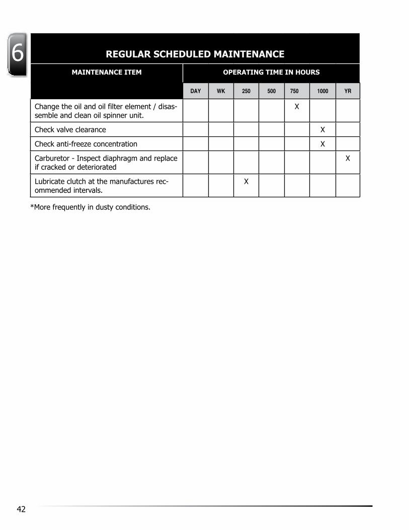
42
6 REGULAR SCHEDULED MAINTENANCE
MAINTENANCE ITEM OPERATING TIME IN HOURS
DAY WK 250 500 750 1000 YR
Change the oil and oil filter element / disas-semble and clean oil spinner unit.
X
Check valve clearance X
Check anti-freeze concentration X
Carburetor - Inspect diaphragm and replace if cracked or deteriorated
X
Lubricate clutch at the manufactures rec-ommended intervals.
X
*More frequently in dusty conditions.

43(800) 331-3662www.ArrowEngine.com
77.1 Basic Requirements
Preservation of engines and generators in stor-age involves several basic requirements. For new engines and generators, these are as follows:
1. Protection of machined metal surfaces, cyl-inders, valves, bearings and so on, from the effects of both dampness and salt or other corrosive substances in the atmosphere.
2. Protection of openings into the engine against the entrance of dirt, abrasive mate-rial and foreign matter of all types.
3. Protection of accessory equipment including carburetors, gas regulators, ignitions, start-ers, alternators and fan belts against corro-sion, dirt, moisture saturation and progressive deterioration.
4. Protection of cooling system intercoolers and LPG vaporizers against freezing, rusting or seizure of water pump seals.
5. Protection of a general nature against the elements - rain, snow and extremes of tem-perature.
6. Protection of batteries by disconnecting and re-moving them to a slow charging station where they can be kept fully charged. If this is ne-glected, the plates may be damaged or ruined by becoming sulfated.
7. Protection of the alternator by covering all openings to prevent the entry of dust, mois-ture, dirt and rodents. A heavy craft paper will serve this purpose, Where these openings are in the form of screened or louvered guards or covered plates, the protective paper should be placed under these removable parts. If this is not possible, a pressure sensitive tape can be used to hold the paper in position. Do not use masking tape - it is not suitable for this type of service and will be very difficult to remove after extended use. Application of protective paper should be on both inside and outside of large fixed louvered surfaces. Large open
7 Engine Storage
areas should have a corrugated cardboard backing for the paper.
8. Protect switchboards in the same manner as the alternators. In the case of engines pre-viously operated, additional items must be considered.
9. Protection of interior engine parts - par-ticularly bearings, cylinder walls and valves against corrosion by the products of combus-tion combined with atmospheric moisture and corrosion by lubricating oil contaminants.
The extent of the attention given to each of the foregoing points of possible damage depends on the judgement of the person in charge of the equipment. Generally speaking, the following factors should be taken into consideration before deciding how much or how little preservation is required.
1. The period of time the equipment is likely to be inoperative.
2. The severity of the weather and atmospheric conditions at the point of storage. The prob-lems of storing equipment in a high humidity area, for example, differ greatly from storage problems in a location where the air is very dry and dusty.
3. The accessibility of the equipment for peri-odic inspection and attention. An engine on a showroom floor that may be turned over occasionally and given periodic oiling requires less extensive treatment than engines crated and stocked in a warehouse.
CAUTIONA-160 engines received from the factory are internally protected for up to six months for storage indoors. If the storage period exceeds six months, the engine should receive additional storage preservatives. Engines stored outdoors or in a humid environment may require more frequent re-preservation.

44
7MAIN SCREENS (3)
FAULT HISTORYGAUGES
7.2 Storing New Engines
Engines recently received from the factory and not intended to be used for an indefinite pe-riod may be stored successfully in the following manner. Engines stored outdoors or in a humid environment may require more frequent re-pres-ervation. Circumstances may compel omitting some steps, while on the other hand, special conditions may point to greater emphasis on other steps.
7.2.1 Engine in Operable Condition1. Mix an inhibitive type preservative oil with
the engine lubricating oil in the proportions recommended by the manufacturer of the preservative oil. Operate engine until oil is hot. Cooling water used in this run should have inhibitor added in accordance to manu-facturers instructions.
2. Remove air cleaners of gas engines With manually operated sprayer, squirt can or other means, inject preservative oil of a suit-able type into the air intake while the engine is running. Approximately one minute is or-dinarily adequate. If possible, stop engine by slugging enough oil through intake to stall. Continue injecting oil until the engine stops turning.
3. Drain oil and water while hot. If extra protec-tion is desired, the rocker arm covers may be removed and a quantity of preservative oil poured over the rocker arm and valve mechanisms.
4. For gas engines not stopped by slugging, remove spark plugs and squirt or spray sev-eral teaspoons of preservative oil into each combustion chamber. Coat spark plugs and reinstall.
5. Wipe engine clean and dry. Apply wax type masking tape or like material to all open-ings such as intake openings in air cleaners, exhaust outlets, breathers and open line fittings.
6. Relieve tension on belts. This is important because continual tension on belts without the working action that occurs in normal op-eration causes deterioration of the rubber.
7. Apply a coating of heavy preservative com-pound with brush to all exposed machined surfaces such as flywheels.
Engines treated in accordance with these instructions will normally be protected for one year or longer. Continual inspection, however, is the only way to determine if protection is adequate. If possible, crank the engine by hand for one or two turns about once a month. This helps prevent seizure of water pump seals. If this is done, however, it is usually best to add more preservative oil to each cylinder. Some types of preservative oil are not well suited to periodic engine rotation because they are scraped from the cylinder walls which are then unprotected. Other oils are not scraped away and for this reason the operator should carefully investigate the characteristics of the preserva-tive oil used.
7.2.2 When Engine is Not Operable1. Open drains as required to remove oil and
water.
2. With hand or mechanical operated atom-izing spray (do not use ordinary compressed air) inject preservation oil into each cylinder.
3. Crank engine in normal direction about one quarter turn and spray each cylinder again. Do this about eight times or until engine has been turned through two complete revolutions. The purpose of this procedure is to expose each valve so it can be coated with oil.
4. Depending on the judgment of the opera-tor as to the severity of storage conditions, open valve rocker covers, gear cover plates and as many points as possible where oil may be sprayed, poured or squirted over the interior parts. Replace all plugs and cov-ers.
5. Remaining steps may be the same as listed in 5 and 6 for an operable engine.

45(800) 331-3662www.ArrowEngine.com
77.3 Storing Engines That Have Been In Service
In the course of normal engine operation, resi-dues of various combustion products, such as sulphur, accumulate in the combustion area and in the lubricating oil. Portions of these residues combine with atmospheric moisture to form cor-rosive compounds of a destructive nature. The following treatment will help reduce the damage from this source:
7.3.1 Engine in Operable ConditionRun engine until the original oil is hot. Drain.
If practical, run the engine with a good flushing oil in crankcase and drain oil and water while still hot.
Refill crankcase with preservative oil or with the proper grade of lube oil to which an inhibitive type preservative oil has been added in the pro-portion recommended.
Carry out previous instructions 5 and 6 as the circumstances indicate.
7.3.2 When Engine is Not OperableCarry out instructions as for an inoperable new engine.
If the judgment of the operator and storage conditions warrant, the engine should be disas-sembled for treatment as a new engine. Ordi-narily this last procedure is unnecessary except in cases where fuels containing considerable sulphur have been used or where extremely bad climatic conditions prevail.
7.4 Preservative Oil
The properties making an oil suitable for pre-servative requirements are good aging stability; high resistance to gumming, oxidation and po-lymerization; low pour point and viscosity; free from acids, asphalts, resins, tars and water.
ENGINE SETTINGS (3 SCREENS)
7.5 Post Storage Engine Preparation
7.5.1 RequirementsThe steps needed to bring an engine into active service after storage in accordance with these instructions are about the same as those nor-mally carried out on any new engine. These are inspection, checking for free rotation, adequate cooling water or antifreeze, ample lubricating oil of the correct type and viscosity and proper adjustments. In addition, accumulated dust and dirt should be wiped or washed from the exte-rior before removing the covers over the engine openings. Removal of installed protection should occur upon normal inspection of the engine generator and switch gear interiors prior to start up. Partial removal may be necessary in the course of installation but this should be kept at a minimum. Engines that have not been rotated for some time should be oiled through the spark plug openings and cranked by hand or with the starting equipment before actually running. Any resistance to free cranking should be investigat-ed - rust and corrosion can cause severe seizure that cannot be forced clear without engine dam-age.
CAUTIONAll generators and switch gear which have been stored must be checked for installation resis-tance with a “megger” prior to being put into service. The megger used should produce 500 V.D.C. Disconnect voltage regulator, rotating diodes, suppressors and any other solid state devices which may be connected to the starter or rotor windings The megger value should be: operating voltage ÷ 1000+1 (i.e. machine volt-age of 480 V.A.C.÷1000=0.480+1=1.480 meg-ohms.) If any circuit to ground measures less than calculated value, consult the Arrow Engine Customer Service Department for any corrective measures as may be necessary.
AUTO-REMOTE MODE

46
7

47(800) 331-3662www.ArrowEngine.com
8equipment and that supplied by the equipment builder.
8.4 Cooling System
The cooling system used on the A-160 is of the pressure circulating type. The water enters the water pump inlet on the right side of the en-gine. The centrifugal pump pulls this supply of cool water through the pump body and into a passage leading directly into the engine water jacket. The water enters the engine in the area of the cylinder sleeve lower ends. From here, the water flow is directed around the cylinder sleeves in an even manner until it passes upward from the crankcase and into the cored passages in the cylinder heads. These passages are care-fully designed to allow cooling water access to all areas around the valves. Water is collected from the cylinder head and enters a thermostat housing at the forward end. The thermostat con-trols the exit temperature of the water. Pressure on the water system should not exceed 7 psi.
8.5 Air Intake System
With the exception of adequate supplies of clean oil and water, probably no other single service item contributes so much to engine life as a properly working air cleaner. This is particularly true under dusty and agricultural operating conditions, but surprising amounts of abrasive dirt are present in most atmospheres. When car-ried into the engine through the air inlet, such abrasives rapidly wear away cylinder walls, valve stems, bearings and other working parts.
Because the dust particles are so small, yet possess the ability to cause great damage, it is absolutely mandatory that air inlet connections be kept in tight condition to avoid taking in unfil-tered air.
Although various installations will have differ-ences in air cleaner types and arrangements, it is important for the operator to realize that the
8.1 Methods
Troubleshooting methods determine the cause or causes of unsatisfactory operation and point out the action needed to correct the problem. Knowledge of how engine systems work to-gether with the troubleshooting chart in this chapter and current indications from the engine instrument panel provide the best background information.
8.2 Operating Controls
A-160 engines are equipped with the following operating controls:
1. Water temperature gauge
2. Oil pressure gauge
3. Throttle
4. Starter switch
5. Ignition switch
8.3 Electrical System
The engine electrical system consists of a heavy duty starter, alternator, switches, and circuits. The engine is started by closing a circuit from battery to starter with the instrument panel switch that actuates the magnetic switch. Posi-tive engagement of the pinion before cranking commences is accomplished by the starting mo-tor solenoid. After cranking is completed and the engine starts, the alternator replenishes energy expended by the battery. Cutouts and regula-tors control the alternators output and protect the system from reverse currents and excessive charging rates. Arrow Engine Company sup-plies engines with negatively grounded electrical equipment only. This standardization of electri-cal system polarity is standard practice for most equipment manufacturers and thus increases compatibility between Arrow supplied electrical
8 Troubleshooting

48
8common purpose of all air cleaners is to collect dirt and grit. Thus the cleaner itself must be cleaned as often as dirt accumulations start to build up. Sometimes this may be several times each day if conditions are especially dusty.
8.6 Exhaust System
Proper disposal of engine exhaust is critical to performance. Engines consume large amounts of air that must be pushed out of the cylinders through the manifolds and exhaust piping. Provision must be made to minimize the restriction or back pressure on the exhaust system.
Some of the adverse effects of excessive back pressure are:
1. Loss of power.
2. Poor fuel economy.
3. Excessive valve temperatures and premature wear.
4. Jacket water overheating.
The exhaust system of an engine with a particularly long exhaust pipe can accumulate quite a bit of condensed moisture. If allowed to run back through the piping into the engine after it is shut down, the obvious rusting and sticking of valves, rings etc. and the possibility of a hydraulic “lock” become serious. Always provide a condensation trap and drain at some low point ahead of the engine mani-folds.

49(800) 331-3662www.ArrowEngine.com
88.7 Troubleshooting Chart
TROUBLESHOOTING CHART
SYMPTOM PROBABLE CAUSE REMEDY
Crankshaft cannot be barred over
CautionDo not attempt to rotate the crankshaft with the starter.
Seized piston. Replace piston assembly and possibly sleeve. Determine cause of the seizure: insufficient ring gap, insufficient lubrica-tion, inadequate cooling or overload.
Coolant or obstruction in the cylinder.
Remove spark plugs and crank engine to vent cylinders of accumulated coolant.
Cracked head. Replace head.
Cracked sleeve. Replace sleeve.
Blown head gasket. Replace head gasket.
Bearings too tight:
1. High spot on bearings. Replace bearings.
2. Improper torque. Loosen bearing caps and re-torque.
3. Main bearing caps installed out of location.
Check each bearing cap, place in proper loca-tion.
Load not disengaged from the engine.
Disengage load.
Engine will crank but not start
Insufficient cranking speed:
1. Run down battery or electric starter malfunction.
Charge or replace battery. Check the starter system, and battery cables.
2. Lube oil viscosity is too high. Change to a lower viscosity oil.
Poor compression:
1. Worn rings. Renew rings.
2. Leaking valves. Recondition head and valves.
3. Leaking head gasket. Replace head gasket.

50
8TROUBLESHOOTING CHART
SYMPTOM PROBABLE CAUSE REMEDY
Engine will crank but not start
(cont’d)
Fuel system inoperative:
1. Insufficient fuel supply Check gas pressure and carburetor ad-justments.
2. Ruptured line pressure regu-lator.
Replace diaphragm.
3. Stiff carburetor diaphragm or worn air-gas valve assem-bly.
Replace air-gas assembly.
4. Bent line pressure regulator control rod.
Replace control rod.
Clogged intake air filter. Remove and clean or replace.
Safety shut-down control not re-set.
Re-set safety shut-down control.
Engine stops suddenly
(cont’d)
Fuel:
1. Insufficient fuel supply. Check gas pressure.
2. Loose fuel control linkage. Readjust and tighten.
3. Clogged fuel supply line. Replace line.
Obstructed exhaust manifold. Determine obstruction and remedy.
Clogged intake air filter. Remove and clean.
Engine overspeed causes safety control to shut down engine.
Determine and correct cause of over-speed.
Excessive load causes engine to stall.
Determine and correct cause of overload.
Piston seizure:
1. Insufficient ring gap (appli-cable only immediately after overhaul.)
Replace scored piston, sleeve and rings. Adjust ring gap.

51(800) 331-3662www.ArrowEngine.com
8TROUBLESHOOTING CHART
SYMPTOM PROBABLE CAUSE REMEDY
Engine stops suddenly
2. Insufficient lubrication. Replace scored piston, sleeve and rings. Clean oil passages and/or determine cause of lack of lubrication.
3. Insufficient cooling. Replace scored piston, sleeve and rings. Clean and/or fill the cooling system.
Seizure of bearing, main con-necting rod, piston pin or cam-shaft.
Replace bearings - clean up or replace crankshaft, camshaft or piston pins as required.
Dirt in lubricating oil. Check lubricating oil filter
Obstruction in cylinder. Replace all parts that failed.
Low oil pressure causes safety control to shut the engine down.
Inspect the lubricating oil system and components and correct the cause.
High coolant temperatures causes safety control to shut down the engine.
Inspect cooling system and components and correct the cause.
Engine power loss
Low compression pressure:
1. Leaking head gasket. Replace head gasket - inspect for warped cylinder head and/or crankcase - replace if necessary.
2. Leaking exhaust-intake valves.
Recondition head and valves.
3. Worn rings (excessive blow-by.)
Replace rings.
4. Worn piston/liner. Replace as necessary.
5. Cracked piston. Replace.
6. Cracked cylinder head. Replace.
7. Maladjusted intake and exhaust valves (if recently overhauled.)
Adjust valves.
8. Intercooler, Turbo or duct work dirty.
Check and clean.
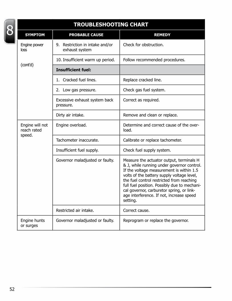
52
8TROUBLESHOOTING CHART
SYMPTOM PROBABLE CAUSE REMEDY
Engine power loss
(cont’d)
9. Restriction in intake and/or exhaust system
Check for obstruction.
10. Insufficient warm up period. Follow recommended procedures.
Insufficient fuel:
1. Cracked fuel lines. Replace cracked line.
2. Low gas pressure. Check gas fuel system.
Excessive exhaust system back pressure.
Correct as required.
Dirty air intake. Remove and clean or replace.
Engine will not reach rated speed.
Engine overload. Determine and correct cause of the over-load.
Tachometer inaccurate. Calibrate or replace tachometer.
Insufficient fuel supply. Check fuel supply system.
Governor maladjusted or faulty. Measure the actuator output, terminals H & J, while running under governor control. If the voltage measurement is within 1.5 volts of the battery supply voltage level, the fuel control restricted from reaching full fuel position. Possibly due to mechani-cal governor, carburetor spring, or link-age interference. If not, increase speed setting.
Restricted air intake. Correct cause.
Engine hunts or surges
Governor maladjusted or faulty. Reprogram or replace the governor.

53(800) 331-3662www.ArrowEngine.com
8TROUBLESHOOTING CHART
SYMPTOM PROBABLE CAUSE REMEDY
Low or fluctuat-ing lubricating oil pressure.
CautionShut downengine immediately
Insufficient oil. Add oil as required.
Gauge inaccurate. Compare to master gauge - replace gauge.
Oil gauge line plugged. Renew gauge line.
Engine operated at angles in excess of maximum safe tilt angles.
Operate within maximum safe tilt angles.
Crankcase oil pressure relief valve relieves at low pressure.
Replace relief valve spring and or shim it to increase pressure to 25-30 psi (172.36-206.84 kPa)
Lubricating oil pressure regu-lating valve stuck in the open position.
Free valve.
Lubricating oil filter plugged (full flow only.)
Change the element and clean the filter.
Worn lubricating oil pump. Repair or replace the pump.
Worn bearing (connecting rod, main and crankshaft.)
Replace worn bearings.
Lubricating oil dilution. Change oil and filter element. Determine and correct the source of dilution.
Cracked or leaking lubricating oil.
Repair or replace the piping.
Low oil viscosity. Change to a higher viscosity oil, as rec-ommended in Lubricating Oil section.
Lubricating oil foaming. Use oil grade recommended in Lubricating Oil section.
Clogged oil inlet screen. Remove and clean screen.

54
8TROUBLESHOOTING CHART
SYMPTOM PROBABLE CAUSE REMEDY
High lubricat-ing oil pres-sure.
Gauge inaccurate. Compare to the master gauge and replace as needed.
Oil temperature too low. Raise temperature.
Oil pressure regulating valve stuck in closed position.
Free valve.
Oil viscosity is too high. Change to a lower viscosity oil as recom-mended in the Lubricating Oil section.
Low cooling water tempera-ture.
Gauge inaccurate. Compare to master gauge - replace as needed.
Inoperative thermostat. Replace thermostat.
High cooling water tempera-ture
CautionCool water slowly.
Gauge inaccurate. Compare to master gauge - replace as needed.
Cooling system is air bound. Purge air from the cooling system.
Low coolant level. Fill cooling system.
Worn water pump. Replace or overhaul the water pump.
Frozen coolant. Completely thaw the cooling system be-fore starting the engine.
Poor coolant circulation. Check entire coolant system.
Blown head gasket. Replace head gasket.
Insufficient circulation of air. Correct as required.
Cracked head. Replace head.
Cracked sleeve. Replace sleeve.
Inoperative thermostat. Replace thermostat.
Late ignition timing. Re-time.
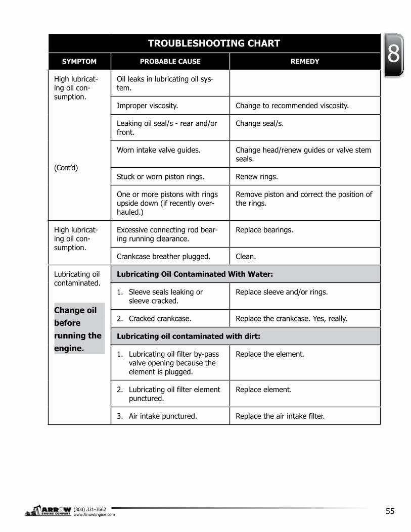
55(800) 331-3662www.ArrowEngine.com
8TROUBLESHOOTING CHART
SYMPTOM PROBABLE CAUSE REMEDY
High lubricat-ing oil con-sumption.
(Cont’d)
Oil leaks in lubricating oil sys-tem.
Improper viscosity. Change to recommended viscosity.
Leaking oil seal/s - rear and/or front.
Change seal/s.
Worn intake valve guides. Change head/renew guides or valve stem seals.
Stuck or worn piston rings. Renew rings.
One or more pistons with rings upside down (if recently over-hauled.)
Remove piston and correct the position of the rings.
High lubricat-ing oil con-sumption.
Excessive connecting rod bear-ing running clearance.
Replace bearings.
Crankcase breather plugged. Clean.
Lubricating oil contaminated.
Change oil before running theengine.
Lubricating Oil Contaminated With Water:
1. Sleeve seals leaking or sleeve cracked.
Replace sleeve and/or rings.
2. Cracked crankcase. Replace the crankcase. yes, really.
Lubricating oil contaminated with dirt:
1. Lubricating oil filter by-pass valve opening because the element is plugged.
Replace the element.
2. Lubricating oil filter element punctured.
Replace element.
3. Air intake punctured. Replace the air intake filter.
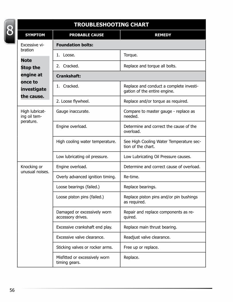
56
8TROUBLESHOOTING CHART
SYMPTOM PROBABLE CAUSE REMEDY
Excessive vi-bration
NoteStop the engine at once to investigate the cause.
Foundation bolts:
1. Loose. Torque.
2. Cracked. Replace and torque all bolts.
Crankshaft:
1. Cracked. Replace and conduct a complete investi-gation of the entire engine.
2. Loose flywheel. Replace and/or torque as required.
High lubricat-ing oil tem-perature.
Gauge inaccurate. Compare to master gauge - replace as needed.
Engine overload. Determine and correct the cause of the overload.
High cooling water temperature. See High Cooling Water Temperature sec-tion of the chart.
Low lubricating oil pressure. Low Lubricating Oil Pressure causes.
Knocking or unusual noises.
Engine overload. Determine and correct cause of overload.
Overly advanced ignition timing. Re-time.
Loose bearings (failed.) Replace bearings.
Loose piston pins (failed.) Replace piston pins and/or pin bushings as required.
Damaged or excessively worn accessory drives.
Repair and replace components as re-quired.
Excessive crankshaft end play. Replace main thrust bearing.
Excessive valve clearance. Readjust valve clearance.
Sticking valves or rocker arms. Free up or replace.
Misfitted or excessively worn timing gears.
Replace.

57(800) 331-3662www.ArrowEngine.com
8

ENGINE COMPANY58
8

ENGINE COMPANY
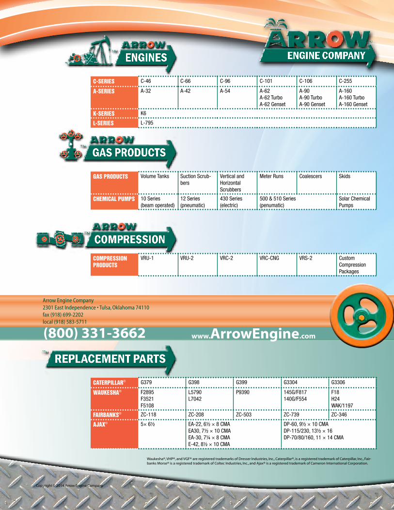
Arrow Engine Company2301 East Independence • Tulsa, Oklahoma 74110fax (918) 699-2202local (918) 583-5711
(800) 331-3662 www. ArrowEngine.com
Waukesha®, VHP®, and VGF® are registered trademarks of Dresser Industries, Inc., Caterpillar®, is a registered trademark of Caterpillar, Inc., Fair-banks Morse® is a registered trademark of Coltec Industries, Inc., and Ajax® is a registered trademark of Cameron International Corporation.
Copyright © 2014 Arrow Engine Company
ENGINE COMPANYENGINES
GAS PRODUCTS
COMPRESSION
REPLACEMENT PARTS
C-SERIES C-46 C-66 C-96 C-101 C-106 C-255
A-SERIES A-32 A-42 A-54 A-62A-62 TurboA-62 Genset
A-90A-90 TurboA-90 Genset
A-160A-160 TurboA-160 Genset
K-SERIES K6
L-SERIES L-795
CATERPILLAR® G379 G398 G399 G3304 G3306
WAUKESHA® F2895F3521F5108
L5790L7042
P9390 145G/F817140G/F554
F18H24WAK/1197
FAIRBANKS® ZC-118 ZC-208 ZC-503 ZC-739 ZC-346
AJAX® 5× 6½ EA-22, 6½ × 8 CMAEA30, 7½ × 10 CMAEA-30, 7¼ × 8 CMAE-42, 8½ × 10 CMA
DP-60, 9½ × 10 CMADP-115/230, 13½ × 16DP-70/80/160, 11 × 14 CMA
GAS PRODUCTS Volume Tanks Suction Scrub-bers
Vertical and Horizontal Scrubbers
Meter Runs Coalescers Skids
CHEMICAL PUMPS 10 Series(beam operated)
12 Series(pneumatic)
430 Series(electric)
500 & 510 Series(penumatic)
Solar Chemical Pumps
COMPRESSION PRODUCTS
VRU-1 VRU-2 VRC-2 VRC-CNG VRS-2 Custom Compression Packages


