42
[Type text] REFRIGERATION & AIR CONDITIONING GUIDE COMPRESSOR TROUBLESHOOTING GUIDE: Understanding the Cooling Cycle 4/17/2009 A1 Compressor, Inc. Horace Park
| Date post: | 31-Jan-2018 |
| Category: |
Documents |
| Upload: | truongkien |
| View: | 236 times |
| Download: | 0 times |
[Type text]
REFRIGERATION & AIR CONDITIONING GUIDE
COMPRESSOR TROUBLESHOOTING GUIDE: Understanding the Cooling Cycle 4/17/2009 A1 Compressor, Inc. Horace Park
A1 COMPRESSOR, Inc COMPRESSOR TROUBLE SHOOTING GUIDE
CONFIDENTIAL QMF -‐ 49
2 REFRIGERATION & AIR CONDITIONING GUIDE April
17,
2009
DYNAMICS OF COMPRESSION
COMPRESSOR TROUBLESHOOTING GUIDE
INDEX
1. Introduction: Function of Compressor 2. Super Heat 3. Charging A System 4. Oils 5. Refrigeration Controls 6. Accumulators 7. Suction Line Filters 8. What is a BTU? 9. Thermostatic Expansion Valves 10. Relay and Cap Assemblies 11. Pump Down Systems 12. Compressor Failures 13. Installing a New Compressor 14. How to Install a New Compressor 15. Brazing & Welding 16. Glossary 17. Refrigeration Cycle 18. Frequently Asked Questions 19. Tecumseh Pressure Control Settings 20. 06E Semi-‐Hermetic compressor Diagram 21. COMPRESSOR INSTALLATION START UP SHEET
(Press CTL + click to follow the hyperlink )
A1 COMPRESSOR, Inc COMPRESSOR TROUBLE SHOOTING GUIDE
CONFIDENTIAL QMF -‐ 49
3 REFRIGERATION & AIR CONDITIONING GUIDE April
17,
2009
1. FUNCTION OF A COMPRESSOR The function of a compressor is the same for either Refrigeration or A/C. It is really very simple. You are essentially transferring heat from one place to another; i.e. cooler, freezer or room. You are never adding cold…you are removing heat. Transferred by low pressure (low temp) Refrigerant in the evaporator and moving it to the condenser where it is High Pressure High Temperature. Usually, the fan moves the lower temp air across the super heated refrigerant high condenser coil cooling it. This is where you feel the heated air. This is the heat removed from the room, cooler or freezer along with the heat of compression from the compressor. This brings me to the next part of compressor function: refrigerant flow. Starting at the discharge line at the compressor you will notice that this is the smallest line and should be the hottest one of the two that is connected to the compressor. The Discharge Line takes the hot refrigerant from the compressor to the condenser where it is cooled changing it from a hot refrigerant to a sub cooled liquid. As the liquid leaves the condenser it will usually go to a receiver tank then to the liquid line sometimes straight to the liquid line depending on the expansion device. The next stage in the process is the Drier. The Drier removes the moisture and debris, if any, from the refrigerant. All Driers have an arrow on them. The arrow should always be pointed toward the evaporator and away from the condensing unit. The Expansion Device follows. There are usually only 3 types: 1. Capillary type; 2. Expansion Type; & 3. Orifice Type. Regardless of the type, they all do the same thing-‐-‐-‐Drop the Pressure which lowers the temperature of the liquid refrigerant below the temperature of the room or box. The cold liquid now enters the evaporator unit, which is located inside the room or box, travelling through the coil where a fan usually blows warmer air across the cold refrigerant boiling it like water on a stove. The cold liquid picks up the heat of the box and at the end of the coil is only a super heated vapor. The super heated vapor travels to the low side of the compressor. This line is the coolest and largest one that is connected to the compressor. Now the compressor sucks the low pressure refrigerant vapor pushing it to a high pressure high temp Vapor where it started its cycle all over again dissipating the heat it has removed from the evaporator.
Back to the Index
A1 COMPRESSOR, Inc COMPRESSOR TROUBLE SHOOTING GUIDE
CONFIDENTIAL QMF -‐ 49
4 REFRIGERATION & AIR CONDITIONING GUIDE April
17,
2009
2. SUPER HEAT SUPER HEAT EXPLAINED Say Super Heat to a mechanic and they will act like they know what it is but often they really don’t understand. Here I will explain what Super Heat is, how to find it and how to set it in simple English. Simply, Super Heat is the temperature of the Suction Line at any given point and the suction pressure converted to temperature (see temp / pressure chart or even the conversion temp inside your gauges R-‐22, etc.). The difference is Super Heat. The Suction Line temp will be the same or higher …It can never be colder than the Chart temp. This chart temp is also the Evaporator Temp. Subtract the conversion chart temperature from the Suction Line Temperature and the difference is SUPER HEAT. So, let’s measure the suction of an A/C unit using R-‐22. For example purposes, let’s say it measures 58 deg. F and we have a 65# suction pressure. Look either at the Green R-‐22 temp inside the suction gauge or look at your Refrigerant Temp Pressure Chart and you will see that 65# suction is 38 deg F. The difference between the 58 deg F we measured to the 38 deg F chart temp is Super Heat or, in this example, 20 deg F of Super Heat. So, what does this mean? Twenty (20) degF of Super Heat at the compressor is ideal. It means that somewhere up the suction line the Liquid Refrigerant has changed to all vapor. All Refrigeration and A/C Compressors are designed to pump vapor not liquid. If the Super Heat is too low, 10 deg F or less, and you will run the risk of damaging the compressor. Low Super Heat will either thin the oil so it doesn’t do its job or it enters the cylinder and can’t get out fast enough. Either way, rods break and you are changing out a compressor. If the Super Heat is too high the compressor will run hot. SETTING SUPER HEAT Rule number 1, SUPER HEAT CHANGES, so to set it properly the Room or Box needs to be at the desired temperature. Setting this is to regulate the amount of liquid left at the end of the Evaporator. This is done by adjusting the Expansion Valve by screwing the adjustment screw-‐-‐-‐ Screwing In raises the Super Heat and Out lowers it. If this is an orifice or capillary tube, first check the box or unit for the weight of refrigerant, the amount of refrigerant and the discharge pressure will set the Super Heat. Less refrigerant will usually raise the Super Heat. Raising and lowering super heat cools the compressor and its oil and head temperature. Ideal is 20 deg at the compressor. Sometimes a short suction line makes this hard to do. In this instance, get what you can. The key point is that you must have Super Heat or a Compressor will be the next thing you change!!!!
Back to the Index
A1 COMPRESSOR, Inc COMPRESSOR TROUBLE SHOOTING GUIDE
CONFIDENTIAL QMF -‐ 49
5 REFRIGERATION & AIR CONDITIONING GUIDE April
17,
2009
3. CHARGING A SYSTEM Charging a system can be somewhat tricky when you take into consideration capillary tubes, head master valves and fan cycle controls and suction pressure regulators. EVACUATING A CHARGED SYSTEM It is necessary before charging any system to remove air and any non-‐condensable that is ion the system. If they are not removed, they will become trapped at the top of the condenser taking up space and robbing the system of its ability to remove heat. The length of time it takes to evacuate a system is only as long as it takes to reach as 25 – 28” of vacuum. Then break the system by adding a small amount of refrigerant to the longest end of the system and allowing it to reach 25 – 28” of vacuum again. Now you are ready to charge the system in the discharge line before turning the system on. The only reason to evacuate a system for a long period of time, such as overnight, is if you feel that the system has water in it. If it does, you better have a real good pump to get the water to boil off in a vacuum otherwise this process can be done usually in 30 minutes or less. CHARGING AN EMPTY SYSTEM Step one is to evacuate the system to remove all non-‐condensable form the system and clean the condenser. This will allow you to get a good idea of when you have enough refrigerant in the system if you don’t know the factory charge. The condenser is designed to remove a certain amount of heat (BTU’s) from the Box or Room usually at 90 deg F of ambient. So if your condenser is clean and you charge the system until the liquid line or drier gets good and warm you are now removing all the heat from the box or room that it is designed to remove your charge should be very close to being correct. Never let the liquid line get Hot!!!! Check your Super Heat after the Box or Room comes down to the desired temperature. ADDING REFRIGERANT Adding refrigerant to a system that has a partial charge has usually three rules of Thumb: 1. Clear the sight glass 2. A Warm the liquid line 3. And, most important, is suction pressure.
With the 100+ refrigerants on the market, always consult your Pressure Chart for the correct suction pressure. If your suction pressure gets too high, you can flood the evaporator with liquid. The correct charge is to have 6 – 10 deg Super Heat at the end of the Evaporator. Remember, the refrigerant needs to be at least 10 deg F colder than the box or the room in order to remove the heat.
A1 COMPRESSOR, Inc COMPRESSOR TROUBLE SHOOTING GUIDE
CONFIDENTIAL QMF -‐ 49
6 REFRIGERATION & AIR CONDITIONING GUIDE April
17,
2009
We have not discussed Discharging Pressures. This is because there are so many refrigerants that discharge pressure could be as little as 100lbs and as much as 350lbs. Discharge temperature is what is important.
CHARGING A SYSTEM WITH A SUCTION LINE REGULATOR This is a somewhat slow and usually wait and see process because, until the box reaches temperature a true suction pressure is unknown. Smaller systems with capillary tubes should be weighed in and the OEM charge needs to be known first. Larger systems with receivers & TEV valves are tough. If the system is empty, look at the receiver to get a good feeling for an amount. If the box is short of refrigerant slowly clear the sight glass. Either way, you must check the Super Heat after the box has reached its temperature. For a Head Master Valve, this is where the tricky part starts. This is a Valve that allows the discharge gas to bypass the condenser in cold ambient (outdoor) conditions. The manufacturer of the equipment usually will give you a certain amount of refrigerant to add to the system after you get a clear sight glass. Not knowing this will allow the equipment to work great just after you fix the leak and charge the system to a full sight glass only to stop or lose temperature when the conditions outside change with a new season. My advice is that if the OEM amount is unknown to charge the system to a clear sight glass or a good warm liquid line and add about 10 – 20% extra for a full charge. The next step is very important. Close the Liquid line and pump the system down watching the high pressure gauge to make sure that the receiver will hold all the refrigerant. If it won’t, the next step is obvious-‐-‐-‐ Remove some of the refrigerant. EVAPORATOR PULLEYS AND BELTS -‐-‐-‐-‐-‐-‐-‐ A/C SYSTEMS One of the most missed A/C problems that can harm a compressor, cause low suction pressure, trap oil in the evaporator, flood the compressor and always cause you to cover charge a system is a worn pulley on the Blower Motor. When the belts become loose, don’t just move the motor. Most systems have an adjustable pulley. Adjust the pulley and bring the motor amps to almost full load amps with the motor cover on. This will allow you to maximize the air flow across the coil, bring the suction pressure up and cause the system to function properly.
Back to the Index
A1 COMPRESSOR, Inc COMPRESSOR TROUBLE SHOOTING GUIDE
CONFIDENTIAL QMF -‐ 49
7 REFRIGERATION & AIR CONDITIONING GUIDE April
17,
2009
4. OILS
There are 3 types of oil generally used in Refrigeration Systems. You need to know why it is important to have the correct oil for the refrigerant that is in the system. The main reason is that in all cooling systems, oil circulates in the system. With the introduction of the new refrigerants, getting the oil to return to the compressor was a problem simply because the new refrigerant and the old oils would not mix. Having said that, the only reason to match the oil to the refrigerants is to get it to return to the compressor. The first and oldest oil is Mineral Oil. This oil has a good lubrication property and was great with old refrigerant (those with chlorine). This oil would foam somewhat so the introduction of Alkybenzene, a synthetic oil, was introduced. It has the same lubrication qualities as Mineral Oil but would not foam aiding in the lubrication factor. These oils will both mix with one another and not cause a problem with the system. In fact, some manufacturers found that a blend of up to 50 – 50 mix of these oils would give better lubrications while keeping foaming to a minimum would actually quiet the Compressors operation. However, these oils should only be used with the old CFC refrigerants such as R-‐12, R-‐22, R-‐502 and their drop end replacements. NEVER use it in the new HFC Refrigerants such as R134A, R404A, R410A, etc. The last and newest oil is Poly Ester or POE. This oil can be used with most all refrigerants, both new and old oil. However, I have many reservations and would only recommend using it in new systems because this oil is made up of alcohol and acid. In plain English, alcohol and soap! It will take an old system and clean it like Mister Clean. Soon the oil becomes jet black with contaminants and must be changed more than once. Also, it will attack any rubber seal and O Ring that is not compatible causing leaks which may not be easily repaired. Therefore, it is advisable to use the Drop in Refrigerants in older systems with Mineral or Alkybenzene oils, POE oils should only be used in new systems with R134A, R404A etc. refrigerants. GETTING OIL TO RETURN ON A/C SYSTEMS This can become a problem in many systems. When any refrigerant runs a low head pressure there is not enough pressure to force the oil through the cold evaporator so it accumulates thus robbing the system of BTU’s and then coming back all at once resulting in a damaged compressor. The key is to regulate the head pressure with a fan cycle switch or a head master valve. My rule of thumb is to have a warm liquid line. This will get your oil back as long as the Evaporator fans are doing their job. A second consideration is adding a P trap. P Traps will also aid in getting oil to return. These are needed when the condensing unit is installed higher than 12’ above the evaporator. ALWAYS INSTALL ONE IN THE SUCTION LINE FOR EVERY 12’ OF VERTICLE RUN.
Back to the Index
A1 COMPRESSOR, Inc COMPRESSOR TROUBLE SHOOTING GUIDE
CONFIDENTIAL QMF -‐ 49
8 REFRIGERATION & AIR CONDITIONING GUIDE April
17,
2009
5. REFRIGERATION CONTROLS There are only a few controls on a normal Refrigeration system. To be a good service technician you must know What they are, What they do and When they do it!! You need to know this in order to know where to set them with different Refrigeration and Box Temperatures. The most common control is the Thermostat. Sounds simple, but does it just cut the compressor off? Or does it cut a solenoid valve off and the Pressure Control cuts the compressor off after the system pumps down? Does it wire through a time clock or does it have a standing defrost cycle where if you set it too cold it will ice the Box up? Does the thermostat have an adjustable differential so you can spread the off cycle so it will keep the box off long enough to defrost? Next is the Pressure Controls. This is usually a Dual Pressure Control where both high and low temperatures are read. The high side part of the control is a safety control in cases of a dirty condenser, a bad fan motor, over charged system and several other reasons that could occur. In those cases, you would want the control to switch the unit off in the case of high discharge Pressure that can damage the valves or head gaskets of the compressor. The other side, or Low Pressure side of this control, also serves as a safety device that shuts the compressor off in the case of a loss of refrigerant. You always want the control to do this without letting the system run into a vacuum. The reason for this is that in a vacuum air will be sucked in introducing moisture into the system. Moisture is the #1 enemy of a refrigeration system. A good rule of thumb to remember is to set this control off at 2 lbs of pressure and on at 30lbs of pressure. This setting will also work fine for a pump down off cycle. The Oil Safety Control is the least understood control in the system because it normally has three wires and everyone panics. The two wires on the marked terminals L and M are only Control Circuit wires meaning they are usually the same wires that go to or from the low, high pressure control. They just series through the oil control again on terminals L & M. This also powers one side of the oil switch. The third wire is the one no one seems to understand what to do with. This wire is either on the 120V terminal or On the 230V terminal depending on the control voltage of the unit. The tricky part is that this wire MUST BE wired to the LOAD side of the contactor with the wires that feed the compressor (230V only) or through a Auxiliary Contact or Relay because it must shut off power to the Oil Control when the compressor is not running. You should never read voltages on the oil safety terminals marked L & 230V L&120 again Depending on your control voltage when the compressor is off and you should always read voltage on these terminals when the compressor is running.

A1 COMPRESSOR, Inc COMPRESSOR TROUBLE SHOOTING GUIDE
CONFIDENTIAL QMF -‐ 49
9 REFRIGERATION & AIR CONDITIONING GUIDE April
17,
2009
The oil safety control usually has a 9lb differential. This means that the oil pressure must be 9lbs over the suction pressure when the compressor is operating. Your oil pressure is always Pump Pressure minus Suction Pressure and it has a 120 second delay usually before the control will shut the system down. All Oil Controls are a manual reset so as not to damage the compressor. I have found that a minimum of 20lbs of oil pressure is needed to have a dependable system. Less that 20lbs and you will find you will have a lot of nuisance service calls to rest this control. I have categorized oil safety trips into three categories:
1. Lubrication problem such as a bad oil pump, low oil and other problems internal to the compressor
2. Zero Super Heat or at the same time in the cycle a low load or an out of adjusted TEV or Icing up accrues during the cycle flooding the compressor with liquid refrigerant which thins the oil to the point where the Oil pressure is below 9 lbs of suction pressure. This is the number 1 cause of compressor failure.
3. Less common and only found in compressors with line voltage over loads usually inside the compressor. When it opens to stop the compressor, the power is still to the compressor but because it is not running no oil pressure is produced and the oil safety is the next thing to trip. Few OEM’s install a current sensing relay that can stop this from happening by reading amp draw of the compressor and dropping out the power supplied to 120 or 230 terminals of the oil switch.
The last two trip types can be very frustrating because by the time you get to the site and reset the oil switch the liquid has boiled out of the oil or the compressor has cooled off and everything is running fine with plenty of oil pressure.
Always look for these causes and remember “Every time you reset an oil safety switch is one compressor you didn’t have to change”.
Back to the Index

A1 COMPRESSOR, Inc COMPRESSOR TROUBLE SHOOTING GUIDE
CONFIDENTIAL QMF -‐ 49
10 REFRIGERATION & AIR CONDITIONING GUIDE April
17,
2009
6. ACCUMULATORS The Refrigeration and Cooling Systems Best Friend!!! It is the best insurance policy you can buy to prevent any liquid refrigerant or oil from reaching the compressor and destroying it. This is a tank that is usually mounted vertically that the suction line runs through to catch any liquid either in the run cycle or the start up cycle. To explain this further, there is nothing good that can come from any liquid refrigerant or large amounts of oil that can return suddenly to the compressor. Small amounts of liquid thin the oil and causes excessive wear from lack of lubrication. This condition is called Liquid Wash. Large amounts returning usually on start up damages rods, valve reeds and blow head gaskets. This is called Liquid Slug or Slugging. Even in the best designed systems, these conditions can occur at one time or another and it only takes one occurrence to cause irreparable damage to the compressor. All accumulators have an “In” on one of the connections. Always point this connection away from the compressor.
Back to the Index
A1 COMPRESSOR, Inc COMPRESSOR TROUBLE SHOOTING GUIDE
CONFIDENTIAL QMF -‐ 49
11 REFRIGERATION & AIR CONDITIONING GUIDE April
17,
2009
7. SUCTION LINE FILTERS This is a filter that is installed in the suction line usually after a bad burn out of the compressor to clean dirty oil and acid stopping it from contaminating the oil in the replacement compressor. It is, in my experience that this is the only reason to install one and it should be removed after the system has run for a week or more. Some of these have replaceable cores. In that case any solid cores should be replaced with felt cores to minimize any pressure drop of oil saturated and dirty cores. There are two things to keep in mind when adding a suction filter:
1. Anything that could reach this filter has already gone through the drier and the TEV valve strainer. So change the drier and check the TEV strainers or risk a pressure drop in these areas.
2. If you install this suction line filter wrong, you can cause it to become an oil trap where large amounts of oil can suddenly return to the compressor and cause harm.
Back to the Index
A1 COMPRESSOR, Inc COMPRESSOR TROUBLE SHOOTING GUIDE
CONFIDENTIAL QMF -‐ 49
12 REFRIGERATION & AIR CONDITIONING GUIDE April
17,
2009
8. WHAT IS A BTU? A BTU is to cooling what horsepower is to a car engine. It is the way we measure the load of an air conditioning or refrigeration system. BTU is an abbreviation for British Thermal Unit. A BTU is the measure of the amount of heat that is required to raise one pound of water 1degF in temperature. These measurements are usually in increments called Tons. Therefore, 12,000BTU’s = 1 Ton. This is a detailed as we need to get as others have done all of the heavy lifting. There are charts available for each brand of compressor or unit chosen. Other resources are load calculation books and software programs that can assist us in sizing any building, house, cooler and freezer. A couple of things you do need to know other than the size is if there are any glass doors in the freezer and coolers. Glass doors really eat up BTU’s. The second is always matching the BTU to a temperature of at least 10 – 15 deg F below the desired room or box. This will allow you to know that there are enough BTU’s to allow the Evaporator to be colder than needed. If it is not, the box will stall and never get to the desired temperature.
Back to the Index
A1 COMPRESSOR, Inc COMPRESSOR TROUBLE SHOOTING GUIDE
CONFIDENTIAL QMF -‐ 49
13 REFRIGERATION & AIR CONDITIONING GUIDE April
17,
2009
9. THERMOSTATIC EXPANSION VALVES ( TEV ) These are also referred to as TEV’s. There are really only two kinds of TEV’s:
1. Internally Equalized 2. Externally Equalized
Internally Equalized TEV’s has only two ports: the inlet and the outlet. It is used with evaporators that also have one inlet and the refrigerant flows back and forth until it reaches the one and only outlet to the evaporator.
Externally Equalized TEV’s has an Inlet and Outlet and a ¼” Equalizer Port on the side of the valve where a ¼” line runs from the end of the Evaporator to the TEV. This Valve is used on the Evaporator with multiple feeder tubes at the start of the Evaporator. When the refrigerant leaves the Outlet of the Valve, it enters a Distributor that distributes the refrigerant into several smaller tubes that go to the beginning of the Evaporator. This Evaporator has a circuit for each Feeder tube. The refrigerant now has a shorter distance to travel as it exits the Evaporator. Each circuit then reaches a common header pipe that now becomes the suction line. This shorter distance is where the equalization comes end to allow for a faster Responding Valve. It has been my experience that Freezers work best with a Maximum Operating Valve (MOP) and should never be used with a suction line press valve at the compressor. This has a maximum set pressure of usually 30 lbs to help keep the load of the compressor after defrost.
Back to the Index
A1 COMPRESSOR, Inc COMPRESSOR TROUBLE SHOOTING GUIDE
CONFIDENTIAL QMF -‐ 49
14 REFRIGERATION & AIR CONDITIONING GUIDE April
17,
2009
10. RELAY & CAPACITOR ASSEMBLIES
Relay and Cap Assemblies are required to start single phase Compressors. They allow compressors to start up under a load. They consist of a relay and starting capacitor for compressors that have Induction Run Windings. However on Capacitor Run Models, a running capacitor is requires. The relay has a coil and a set of normally closed contacts where the starting capacitor is removed from the circuit after the Compressor has started and has produced enough voltage between the common terminal and the start terminal to energize coil in the relay. This voltage that is produced in all electric motors while running and is called Electro-‐Motive Force ( EMF).
The starting capacitor is usually the plastic capacitor and is in the circuit for only a second or less This really advances the field inside the motor so it has the torque needed to start. It is always best to have a Bleed Down Resistor of between 15,000 and 18,000 Ohms of resistance attached. This will expand its life and will also help the relay contacts by removing some of the arch that takes place when the contacts open. It will always have a higher MFD ( microfarad) reading than the Run Capacitor.
Running Capacitors are usually metal and are wired to the Start and Run terminals all the time. This advances the field inside the motor slightly which in turn reduces the amperage draw lowering the heat produced in the motor.
The failure of any one of these can mimic a bad compressor that fails to start. It has been my experience that usually the Relay and Starting Capacitor should be replaced first because the Running Capacitor very rarely fails. Replacing the Relay and Starting Capacitor should always be done before changing the compressor. For the relatively small expense it is money well spent.
Back to the Index
A1 COMPRESSOR, Inc COMPRESSOR TROUBLE SHOOTING GUIDE
CONFIDENTIAL QMF -‐ 49
15 REFRIGERATION & AIR CONDITIONING GUIDE April
17,
2009
11. PUMP DOWN SYSTEMS
Pump Down Systems require a Liquid Line solenoid, a thermostat and, in most cases, a time clock. In addition, the condensing unit must have a Low Pressure Switch and Receiver Tank. The liquid suction line is wired through the thermostat and time clock so when the box is satisfied or it is time to defrost it drops power to the solenoid causing the system to start a pump down where all the refrigerant is pumped into the condenser and receiver tank as the suction pressure drops. The low pressure switch shuts down the system. This design has two advantages:
1. In the startup mode, the solenoid opens and the low pressure switch starts the compressor up, there is less chance of a Slug of liquid damaging the compressor.
2. Defrosting the coil is made easier and faster because there is no liquid refrigerant in the evaporator to boil off first before the ice can melt.
Remember, in this type of set up the only things that cuts the compressor off is the low pressure switch and any other safety device such as the Oil Safety Switch.
Back to the Index

A1 COMPRESSOR, Inc COMPRESSOR TROUBLE SHOOTING GUIDE
CONFIDENTIAL QMF -‐ 49
16 REFRIGERATION & AIR CONDITIONING GUIDE April
17,
2009
12. COMPRESSOR FAILURES As you read this section, I want you to remember one thing-‐-‐-‐-‐ 98% of all compressor failures are due to a problem with the system that causes the compressor to fail. Compressors don’t fail without a contributing causal event. If you don’t find this problem with the system and correct it, the replacement compressor will also soon fail. Some of the most common contributors to compressor failure are:
1. Dirty Evaporator or Condenser 2. Loose Evaporator Fan Belts 3. Improper Refrigerant Charge 4. Misadjusted Expansion Valve 5. Controls Out of Adjustment 6. Worn Relays and Contactors
A compressor failure is usually diagnosed in two categories: 1. Mechanical 2. Electrical
Mechanical Failures are usually caused by flood back that washes the oil away or dilutes the oil to a point where excessive wearing occurs on the bearings, rods and pistons. This means at some point in the cycle the Super Heat reaches 0 deg F and the liquid refrigerant starts entering the compressor. The refrigerant must pick up enough heat to boil off all liquid to a vapor state so as not to damage the compressor. Remember, all refrigeration compressors are designed to pump only vapor not liquid refrigerant. Another common mechanical failure is caused by slugging. Slugging usually occurs on start up where liquid refrigerant and oil migrate collecting in the bottom of the evaporator or in the suction line. When the system starts up it enters the compressor damaging the rods, piston, valve plates and / or blows the gaskets. Electrical Failures are caused by a bad supply of power to the compressor. Look for short cycling, a bad capacitor or breaker or even a recent storm that caused a power interruption. Single phase compressors may have a bad relay or capacitor. It is important to understand that contactors, relays and capacitors have a life span and should be replaced periodically. Electrical failures, however, are also the end result of the two. Mechanical failures that we discussed earlier where the rotor drags or the compressor locks up and resulting in the motor burning. To sum up, Compressors always fail because of another problem within the system. A good preventative maintenance program will almost always save the compressor.
Back to the Index
A1 COMPRESSOR, Inc COMPRESSOR TROUBLE SHOOTING GUIDE
CONFIDENTIAL QMF -‐ 49
17 REFRIGERATION & AIR CONDITIONING GUIDE April
17,
2009
13. INSTALLING A NEW COMPRESSOR When installing a new compressor there are a few things you need to check and do. Always replace the Relay on a single phase system. On a three phase system visually check the points on the contactor. Change the drier and suction line filter. Pull a vacuum on the system to remove any non-‐condensable or air. Then add refrigerant to the high side of the system. Because the system is in vacuum most if not all of the refrigerant can be installed in this manner. On larger systems you are ready to do a dry run. Without the power leads connected to the compressor ( leave them taped and in a place where they can’t touch anything) and turn the system ON. If it has a solenoid, watch the suction pressure rise and listen for and at what pressure does the contactor pull in and if it has a safety oil switch how long does it take before the system shuts down. This may not occur if the system has a current sensing relay. Now turn the power off and install the power leads to the compressor; reset the oil safety switch and turn the system ON. It is always good to check the Oil Pressure at this time it is always minus the suction pressure. However, if we know our oil safety switch is working we should be safe. Always know what the full load amp draw is supposed to be. Now check the Amps of the compressor if the room or box is hot it will be close to the FLA. On freezers, check to see that the evaporator fans are cycling on and off as the coil gets below 32 deg F. They should always have a fan and defrost termination switch to keep the load off the compressor after defrost and will also stop the heaters from coming on when the box is hot. With the system running and making sure that the condenser motors are all working properly, feel the liquid line or drier. They should be very warm to the touch but NEVER hot. This will tell you that that you are removing all of the heat that the condenser is designed to remove and that the compressor is working properly. At this point, if you feel the charge of refrigerant and your gauge readings are correct for the evaporator temperature, raise the thermostat to bring the system off of it’s off cycle. If it’s a pump down cycle, watch your suction gauge to see where the control cuts the compressor off. Now bring the system back on. All commercial A/C and Refrigeration systems should start back up unless the control system has a delay built in. After the compressor has started up allow the system to pull down the temperature to the coldest setting. Now you can check the Super Heat. I prefer 20 deg F at the compressor but as little as 10 deg F is acceptable when the suction line is short. This can be obtained by adjusting the TEV. Usually, closing IN will raise the Super Heat and OUT will lower Super Heat. This is best done by a follow up visit the next day where you can check the refrigerant charge, oil level and the defrost system of a freezer.
A1 COMPRESSOR, Inc COMPRESSOR TROUBLE SHOOTING GUIDE
CONFIDENTIAL QMF -‐ 49
18 REFRIGERATION & AIR CONDITIONING GUIDE April
17,
2009
INSTALLING UNLOADERS -‐-‐-‐-‐ A/C SYSTEMS
As a rule of thumb, you usually want a compressor to start unloading at 60 – 62 lbs of suction and back to load at 72 – 74 lbs of suction on R-‐22. Systems that have more than one Unloader should have a solenoid or some way of controlling the decreasing Super Heat that will occur if the system is unloading two or more times.
For example, if a 30 ton compressor unloads twice you could have a 30 ton TEV on now a 10 ton compressor.
Back to the Index
A1 COMPRESSOR, Inc COMPRESSOR TROUBLE SHOOTING GUIDE
CONFIDENTIAL QMF -‐ 49
19 REFRIGERATION & AIR CONDITIONING GUIDE April
17,
2009
14. HOW TO INATALL A COMPRESSOR
INSTALLING A NEW COMPRESSOR CHECKLIST
1. Check the tag for the correct model and voltage 2. Turn the power source off. 3. Front seat service valves and remove refrigerant from the compressor. 4. Mark control lines and electrical wires. 5. Remove service valves and clean gaskets. 6. Remove mounting nuts and old compressor. 7. Clean the condenser. 8. Inspect contact or contactors ( 3 phase ). Replace relay and capacitor ( single phase ) 9. Install new compressor, service valves and control lines, 10. Install Drier. 11. Evacuate Compressor or system and back seat service valves. 12. Tape lead wires and dry run compressor’s with oil safety switch to check its operation. 13. Reconnect lead wires. 14. Start Compressor system and charge. 15. Check amp draw and compare to FLA on the name tag. 16. Check evaporator fans. ( Freezers should have a fan delay switch) 17. Check oil level and oil pressure ( pump pressure – suction pressure = oil pressure ) 18. Check controls for operation (LP, O.I.P., Thermostat Time Clock ) 19. After desired temp is reached check amp draw, oil level, defrost, and Super Heat ( 20 degF at
the compressor)
Back to the Index
A1 COMPRESSOR, Inc COMPRESSOR TROUBLE SHOOTING GUIDE
CONFIDENTIAL QMF -‐ 49
20 REFRIGERATION & AIR CONDITIONING GUIDE April
17,
2009
15. BRAZING & SOLDERING
BRAZING Brazing, also known as silver solder or silfloss, is the choice of most mechanics. Brazing is a requirement on Discharge Lines in particular where high temps are in the 200 – 300 degree F range which would compromise any solder such as Stay Brite or 95-‐5. When Brazing, however, you must bring the copper, brass or steel to redness to get a good penetration of the rod. It is recommended you use a 15% silver for copper to copper. Any less percentage and the impurities will bubble making an ugly joint resulting in a less dependable weld. Forty (40%) percent silver should always be used for unlike metal to metal welds such as copper to brass and especially copper to steel. Using silver brazing flux is a must in all brazing applications. Not using 40% silver or silver flux on unlike metals and your weld is about as dependable as a $5.00 tire even to the point of blowing out. The larger the pipe = the greater the risk.
SOLDERING Most mechanics don’t solder. If you choose this method, try 95/5 or Silver Solder and liquid flux such as Stay Clean and you will change your mind. Never use this method on discharge lines. But to use it and get the hang of it…..is to like it!!, providing you don’t plug the line up. Remember a little goes a long way. Soldering means less worrying about damaging the expansion valves, solenoid valves, etc. How many times have you seen mechanics brazing lines in close or hard to get to places. Remember, “To Braze Means Cherry Red”. Learning to solder is simple and you can usually do one metal to the other with only one flux and one solder with the exception of aluminum. Epoxy is the best method of repairing aluminum outside of heli-‐arching. HOW TO SOLDER
1. Join the pipes or fittings together and warm the joint. 2. Squirt the liquid flux onto the joint to be soldered. 3. Heat the joint evenly and apply the solder. Remember, not too hot and as in Brazing, the
solder will flow to the heat. 4. Let it cool and wipe the joint with a wet rag to remove the flux left on it. Failing to
remove the flux will cause the joint to turn green over time. This joint is tough, faster and has a less chance of melting or damaging anything nearby. Try this method and you can Thank Me later!!!!
Back to the Index
A1 COMPRESSOR, Inc COMPRESSOR TROUBLE SHOOTING GUIDE
CONFIDENTIAL QMF -‐ 49
21 REFRIGERATION & AIR CONDITIONING GUIDE April
17,
2009
16. Glossary
A Alternating Current (AC):
Electric current in which the direction of flow alternates or changes. In 60 cycles current direction of flow reverses every 1/20th of a second.
Ambient Temperature: Temperature of fluid (usually air) which surrounds object on all sides. Ammeter: An electric meter used to measure a current, calibrated in amperes. Ammonia:
Chemical combination of nitrogen and hydrogen (NH3). Ammonia refrigerant is identified by R-‐117.
Amperage: Electron or current flow of one coulomb per second past a given point in circuit. Armature: Revolving part in electric motor or generator. Atmospheric Pressure: Pressure that gases in air exert upon the earth; measured in pounds per square inch. Atomize: Process of changing liquid to minute particles, or a fine spray. Azerotropic Mixture;
Examples of azerotropic mixture -‐-‐-‐ refrigerant R-‐502 are mixture consisting of 48.8% refrigerant R-‐22, and 51.2% R-‐115. The refrigerants do not combine chemically, yet azerotropic mixture provides the desired refrigerant characteristics.
B
Back Pressure: Pressure in low side of refrigerating system; also called suction pressure or low side pressure.
Barometer: Instrument for measuring atmospheric pressure. It may be calibrated in pounds per square inch or in inches of mercury in column.
Bellows: Corrugated cylinder container which moves as pressures change, or provides a seal during movement of parts.
Bimetal Strip:
A1 COMPRESSOR, Inc COMPRESSOR TROUBLE SHOOTING GUIDE
CONFIDENTIAL QMF -‐ 49
22 REFRIGERATION & AIR CONDITIONING GUIDE April
17,
2009
Temperature regulating or indicating device that works on principle that two dissimilar metals with unequal expansion rates welded together, will bend as temperatures change.
Boiling Temperature: Temperature at which a fluid changes from a liquid to a gas. Brazing:
Method of joining metals with non-‐ferrous filler (without iron) using heat between 80 deg F and melting point of base metals.
British Thermal Unit ( BTU): Quantity of heat required to raise temperature of one pound of water one degree F. Butane: Liquid hydrocarbon (C4H10) commonly used as fuel for heating process. C Capacitor:
Type of electrical storage device used in starting and/or running circuits in many electrical motors.
Capacitor-‐Start Motor: Motor which has a capacitor in the starting circuit. Capillary Tube:
A type of refrigerant control. Usually consists of several feet of tuning having small inside diameter. Friction of liquid refrigerant and bubbles of vaporized refrigerant within tube serve to restrict flow so that correct high side and low side pressures are maintained while the compressor is operating. A capillary tube refrigerant control allows high side and low side pressures to balance during off cycle. Also, small diameter tubing used to connect temperature control bulbs to control mechanisms.
Compound of carbon and oxygen which is sometimes used as a refrigerant. Refrigerant number is R-‐744.
Cascade Systems: Arrangement in which two or more refrigerating systems are used in series; uses cooling coil of one machine to cool the condenser of the other machine. Produces ultra-‐low temperatures.
Celsius: German language word for Centigrade, the metric system temperature scale. Centigrade Scale:
Temperature scale used in metric system. Freezing point of water is); boiling point is 100.
Centimeter: Metric unit of linear measurement which equals .3937 inches. Centrifugal Compressor: Compressor which compresses gaseous refrigerants by centrifugal force. Circuit, Parallel:
Arrangement of electrical devices in which all positive terminals are joined to one conductor and all negative terminals to other conductor.

A1 COMPRESSOR, Inc COMPRESSOR TROUBLE SHOOTING GUIDE
CONFIDENTIAL QMF -‐ 49
23 REFRIGERATION & AIR CONDITIONING GUIDE April
17,
2009
Cold: Cold is the absence of heat; a temperature considerably below normal. Compound Gauge: Instrument for measuring pressures both above and below atmospheric pressure.
Compound Refrigerating Systems: System which has several compressors or compressor cylinders in series. The system is used to pump low pressure vapors to condensing pressures.
Compression: Term used to denote increase of pressure on a fluid by using mechanical energy. Compressor:
The pump of a refrigerating mechanism which draws vacuum or low pressure on cooling side of refrigerant cycle and squeezes or compresses the gas into the high pressure or condensing side of the cycle.
Compressor, Hermetic: Compressor in which driving motor is sealed in the same dome or housing that contains the compressor.
Compressor, Open Type: Compressor in which the crankshaft extends through the crankcase and is driven by an outside motor.
Compressor, Reciprocating: Compressor which uses a piston and cylinder mechanism to provide pumping action. Compressor, Rotary:
A compressor which uses vanes, eccentric mechanisms or other rotating devices to provide pumping action.
Condensate: Fluid which forms on an evaporator. Condensation: Liquid or droplets which form when a gas or vapor is cooled below its dew point. Condense: Action of changing a gas or vapor to a liquid. Condenser:
The part of refrigeration mechanism which receives hot, high pressure refrigerant gas from compressor and cools gaseous refrigerant until returns to liquid state.
Condenser, Air Cooled: A heat exchanger which transfers heat to surrounding air. Condenser, Water Cooled:
Heat exchanger which is designed to transfer heat from hot gaseous refrigerant to water.
Condensing Unit: That part of refrigerating mechanism which pumps vaporized refrigerant from evaporator, compresses it, liquefies it in the condenser and returns the liquid refrigerant to refrigerant control.
Condensing Unit Service Valves;

A1 COMPRESSOR, Inc COMPRESSOR TROUBLE SHOOTING GUIDE
CONFIDENTIAL QMF -‐ 49
24 REFRIGERATION & AIR CONDITIONING GUIDE April
17,
2009
Shut off hand valves mounted on condensing unit to enable the service technician to install and/or service the unit.
Conductivity: Ability of metal or a substance to conduct or transmit heat and/or electricity. Crankshaft Seal: Leak proof joint between crankshaft and compressor body. Current Relay: Device which opens or closes control circuits. D Defrost Cycle: Refrigerating cycle in which evaporator frost and ice accumulation is melted. Defrost Timer:
Device connected into electrical circuit which shuts unit off long enough to permit ice and frost accumulation on evaporator to melt.
Dew Point: Temperature at which vapor (at 100% humidity) begins to condense and deposit as liquid.
Differential: As applied to refrigeration and heating; difference between “cut-‐in” and “cut-‐out” temperature and pressure of a control.
Drier: A substance or device used to remove moisture from a refrigeration system. Dry Bulb:
An instrument with sensitive element which measures ambient (moving) air temperature.
Dry Bulb Temperature: Air temperature as indicated by an ordinary thermometer. Dry Ice:
A refrigerating substance made of solid carbon dioxide which changes directly from a solid to a gas (sublimates). Its subliming temperature is 109deg F below zero.
E Eccentric:
A circle or disk mounted off center. Eccentrics are used to adjust controls and connect compressor drive shafts to pistons.
Electric Defrosting: Use of electric resistance heating coils to melt ice and frost off evaporators during defrosting.
Electromotive Force (EMF) Voltage: Electrical force which causes current ( free electrons) to flow or move in an electrical circuit. Unit of measurement is the volt.
Electronic Leak Detector:
A1 COMPRESSOR, Inc COMPRESSOR TROUBLE SHOOTING GUIDE
CONFIDENTIAL QMF -‐ 49
25 REFRIGERATION & AIR CONDITIONING GUIDE April
17,
2009
Electronic instrument which measures electronic flow across gas gap. Electronic flow changes indicate presence of refrigerant gas molecules.
End Play: Slight movement of shaft along center line. Equalizer Tube: Device used to maintain equal pressure or equal liquid levels between two containers. Evaporation: A term applied to the changing of a liquid to a gas. Heat is absorbed in this process.
Evaporative Condenser: A device which uses open spray or spill water to cool a condenser. Evaporation of some of the water cools the condenser water and reduces water consumption.
Evaporator Coil: Device made of a coil of tubing which functions as a refrigerant evaporator. Expansion Valve:
A device in a refrigerating system which maintains a pressure difference between the high side and the low side and is operated by pressure.
External Equalizer: Tube connected to low pressure side of an expansion valve diaphragm and to the exit of evaporator.
F Fahrenheit Scale:
On a Fahrenheit thermometer, under standard atmospheric pressure, boiling point of water is 212 deg F and freezing point is 32 deg F above zero on its scale.
Flash Point: Temperature at which oil will give off sufficient vapor to support a flash flame but will not support continuous combustion.
Flux – Brazing, Soldering: Substance applied to surfaces to be joined by brazing or soldering to free them from oxides and facilitate a good joint.
Foaming: Formation of a foam in an oil refrigerant mixture due to rapid evaporation of refrigerant dissolved in the oil. This is most likely to occur when the compressor starts and the pressure is suddenly reduced.
Frost Back: Condition in which liquid refrigerant flows from evaporator into suction line; indicated by frost formation on the suction line.
G Gas – Noncondensible: A gas which will not form into a liquid under pressure temperature conditions.
A1 COMPRESSOR, Inc COMPRESSOR TROUBLE SHOOTING GUIDE
CONFIDENTIAL QMF -‐ 49
26 REFRIGERATION & AIR CONDITIONING GUIDE April
17,
2009
Gauge, Compound: Instrument for measuring pressures both below and above atmospheric pressure. Gauge, High Pressure: Instrument for measuring pressures in the range of 0 psig and 500 psig. Gauge, Low Pressure: Instrument for measuring pressures in the range of 0 psig and 50 psig. Gauge, Vacuum: Instrument used to measure pressures below atmospheric pressure. Ground, Short Circuit:
A fault in an electrical circuit allowing electricity to flow into the metal parts of the structure.
Ground Wire: An electrical wire which will safely conduct electricity from a structure into the ground.
H Halide Refrigerants: Family of refrigerants containing halogen chemicals. Head Pressure: Pressure which exists in condensing side of refrigerating systems. Head Pressure Control:
Pressure operated control which opens electrical circuit if high side pressure becomes excessive.
Heat: Form of energy the addition of which causes substances to rise in temperature; energy associated with random motion molecules.
Heat Exchanger: Device used to transfer heat from a warm or hot surface to a cold or cooler surface. Evaporators and condensers are heat exchangers.
Heat Load: Amount of heat, measured in BTU, which is removed during a period of 24 hours. Heat of Compression: Mechanical energy of pressure transformed into energy of heat. Heat Pump:
A compression cycle system used to supply heat to a temperature controlled space, which can also remove heat from the same space.
Heat Transfer: Movement of heat from one body or substance to another. Heat may be transferred by radiation, conduction, convection or a combination of these three methods.
Hermetic Motor: Compressor drive motor sealed within the same casing which contains the compressor.
Hermetic System:
A1 COMPRESSOR, Inc COMPRESSOR TROUBLE SHOOTING GUIDE
CONFIDENTIAL QMF -‐ 49
27 REFRIGERATION & AIR CONDITIONING GUIDE April
17,
2009
Refrigeration system which has a compressor driven by a motor contained in compressor dome or housing.
High Pressure Cut-‐Out: Electrical control switch operated by the high side pressure which automatically opens electrical circuit if too high head pressure or condensing pressure is reached.
High Side: Parts of a refrigerating system which are under condensing or high side pressure. Horsepower:
A unit of power equal to 33,000 foot pounds of work per minute. One electrical horsepower equals 746 watts.
Hot Gas Bypass: Piping system in refrigerating unit which moves hot refrigerant gas from condenser into low pressure side.
Hot Gas Defrost: A defrosting system in which hot refrigerant gas from the high side is directed through evaporator for short period of time and at a predetermined intervals in order to remove frost from evaporator.
Humidity: Moisture; dampness. Relative humidity is ratio of quantity of vapor present in air to greatest amount possible at a given temperature.
Hydroscopic: Ability of a substance to absorb and retain moisture and change physical dimensions as its moisture content changes.
K Kilowatt: Unit of electrical power, equal to 1000 Watts. J L Latent Heat:
Heat energy absorbed in process of changing form of substance ( melting, vaporizing, and fusion ) without change in temperature or pressure.
Liquid Absorbent: A chemical in liquid form which has the property to “take on” or absorb moisture. Liquid Indicator:
Device located in liquid line which provides a glass window through which liquid flow may be observed.
Liquid Line: The tube which carries liquid refrigerant from the condenser or liquid receiver to the refrigerant control.
A1 COMPRESSOR, Inc COMPRESSOR TROUBLE SHOOTING GUIDE
CONFIDENTIAL QMF -‐ 49
28 REFRIGERATION & AIR CONDITIONING GUIDE April
17,
2009
Liquid Receiver: Cylinder connected to condenser outlet for storage of liquid refrigerant in a system. Low Side: That portion of a refrigerating system which is under the lowest evaporating pressure. Low Side Pressure Control:
Device used to keep low side evaporating pressure from dropping below certain pressure.
M Megohmmeter:
An instrument for measuring extremely high resistance ( in the millions of ohms ranges).
Microfarad: Unit of condenser electrical capacity equal to one millionth of a farad. Micron: Unit of length in metric system; a thousandth part of one meter. Motor 2-‐Pole: A 3600 RPM electric motor (synchronous speed ). Motor 4-‐Pole: An 1800 RPM electric motor ( synchronous speed ) Motor Burnout: Condition in which the insulation of electric motor has deteriorated by overheating. Mullion: Stationary part of a structure between two doors. Mullion Heater:
An electrical heating element mounted in the mullion and used to keep mullion from sweating or frosting.
N Natural Convection: Movement of a fluid caused by temperature differences ( density changes ) Noncondensable Gas: Gas which does not change into a liquid at operating temperatures and pressures. O OHM (R) : Unit of measurement of electrical resistance in ohms. Oil, Refrigeration:
Specially prepared oil used in refrigerator mechanism circulates to some extent with refrigerant. The oil must be dry, otherwise, moisture will condense out and freeze in
A1 COMPRESSOR, Inc COMPRESSOR TROUBLE SHOOTING GUIDE
CONFIDENTIAL QMF -‐ 49
29 REFRIGERATION & AIR CONDITIONING GUIDE April
17,
2009
the refrigerant control and may cause refrigerant mechanism to fail. Oil must be free of moisture and other contaminants.
Oil Separator: Device used to remove oil from gaseous refrigerant. Open Circuit: An interrupted electrical circuit which stops flow of electricity. Overload Protector:
A device, either temperature, pressure, or current operated, which will stop operation of unit if dangerous conditions arise.
P Piston Displacement: Volume displaced by piston as it travels length of stroke.
Potential, Electrical: The electrical force which moves or attempt to move electrons along a conductor or resistance.
Potential Relay Voltage: Electrical switch which is operated by voltage changes in electromagnet. Power Element: Sensitive element of a temperature operated control. Pressure Drop:
The pressure difference at two ends of a circuit, or part of a circuit, the two sides of a filter, or the pressure difference between the high side and the low side in a refrigerator mechanism.
Pressure Motor Control: A dev ice which opens and closes an electrical circuit as pressures change to desired pressures.
Pressure Regulator, Evaporator: An automatic pressure regulating valve. Mounted in the suction line between evaporator outlet and compressor inlet. Its purpose is to maintain a predetermined pressure and temperature in the evaporator.
Pressure Suction: Pressure in low pressure side of the refrigerating system. PSI: A symbol or initials used to indicate pressure measured in pounds per square inch. PSIG:
A symbol or initials to indicate pressure in pounds per square gauge. The “g” indicates that it is gauge pressure not absolute pressure.
Psychrometer or Wet Dry Hygrometer: An instrument for measuring the relative humidity of atmospheric air. Pull Down:
An expression indicating action of removing refrigerant from all or part of the refrigerating system.
A1 COMPRESSOR, Inc COMPRESSOR TROUBLE SHOOTING GUIDE
CONFIDENTIAL QMF -‐ 49
30 REFRIGERATION & AIR CONDITIONING GUIDE April
17,
2009
Purging: Releasing compressed gas to atmosphere through some part or parts for the purpose of removing contaminants from that part or parts.
R
Radiant Heating: Heating system in which warm or hot surfaces are used to radiate heat into the space to be conditioned.
Receiver-‐Drier: A cylinder in a refrigerating system for storing liquid refrigerant and which also holds a quantity of desiccant.
Reciprocating: Action of which the motion is back and forth in a straight line. Reed Valve: Thin flat tempered steel plate fastened at one end. Refrigerant:
Substance used in a refrigeration system to absorb heat in evaporator coil by change of state from a liquid to a gas, and to release its heat in a condenser as the substance returns from the gaseous state back to a liquid state.
Relief Valve: Safety device designed to open before dangerous pressure is reached. Remote System:
Refrigerating system which has condensing unit located outside and separate from the refrigerator cabinet.
Resistance ( R ), Electrical: The difficulty electrons encounter moving through a conductor or substance. Reversing Valve:
Device used to reverse direction of the refrigerant flow depending upon whether heating or cooling is desired.
Rotary Compressor: Mechanism which pumps fluid by using rotary motion. Running Winding:
Electrical winding of motor which has current flowing through it during normal operation of the motor.
S Saddle Valve ( Tap_A_Line): Valve body shaped so it may be silver brazed to refrigerant tubing surface.
A1 COMPRESSOR, Inc COMPRESSOR TROUBLE SHOOTING GUIDE
CONFIDENTIAL QMF -‐ 49
31 REFRIGERATION & AIR CONDITIONING GUIDE April
17,
2009
Safety Control: Device which will stop the refrigerating unit if unsafe pressures and/or temperatures are reached.
Safety Plug: Device which will release the contents of a container above normal pressure conditions and before rupture pressures are reached.
Saturation: Condition existing when substance contains maximum of another substance for that temperature and pressure.
Sub Cooling: Cooling of liquid refrigerant below its condensing temperature.
Suction Line: Tube or pipe used to carry refrigerant gas from evaporator to compressor. Suction Pressure Control Valve:
Device located in the suction line which maintains constant pressure in evaporator during running portion of the cycle.
Suction Service Valve:
A two-‐way manual-‐operated valve located at the inlet to compressor, which controls suction gas flow and is used to service unit.
Super Heat: Temperature of vapor above boiling temperature of its liquid at that pressure. Sweating:
This term is used two different ways in refrigeration work: 1. Condensation of moisture from air on cold surface; and 2. Method of soldering in which the parts to be joined are first coated with a thin layer of solder.
T Tap – A – Line:
Device use to puncture or tap a line where there are no service valves available; sometimes called a saddle valve.
Temperature: Degree of hotness or coldness as measured by a thermometer; measurement of speed of motion of molecules.
Thermodisk Defrost Control: Electrical switch with bi-‐metal disk which is controlled by electrical energy. Thermostat: Dev ice responsive to ambient temperature conditions. Thermostatic Control:
Device which operates the system or part of the system based on temperature changes.
Thermostatic Expansion Valve: A control valve operated by temperature and pressure within evaporator coil, which controls flow of refrigerant. Control bulb is attached to outlet of coil.
A1 COMPRESSOR, Inc COMPRESSOR TROUBLE SHOOTING GUIDE
CONFIDENTIAL QMF -‐ 49
32 REFRIGERATION & AIR CONDITIONING GUIDE April
17,
2009
Three – Phase: Operating by means of combination of three alternating current circuits which differ in phase by one-‐third of a cycle.
Ton of Refrigeration: Refrigerating effect equal to the melting of one ton of ice in 24 hours. This may be expressed as follows:
2888,000 Btu / 24 hours 12,000 Btu / 1 hour 200 Btu / minute.
Transformer: Device which transfers electrical energy from primary circuit, into variations of voltage in secondary circuit by electromagnetic induction.
V Vacuum: Reduction in pressure below atmospheric pressure.
Vacuum Pump: Special high efficiency compressor used for creating high vacuums for testing or drying purposes.
Valve, Expansion Type of refrigerant control which maintains pressure difference between high side and low side pressure in refrigerating mechanism. Valve is caused to operate by pressure in low or suction side. Often referred to as an automatic expansion valve or AEV.
Valve Plate: Part of the compressor located between top of compressor body and head which contains compressor valves.
Valve, Solenoid: Valve actuated by magnetic action by means of an electrically energized coil. Vapor, Saturated:
A vapor condition which will result in condensation into droplets of liquid as vapor temperature is reduced.
Voltmeter: Instrument for measuring voltage action in an electrical circuit. Volumetric Efficiency:
Term used to express the relationship between the actual performance of a compressor or of a vacuum pump based on its displacement verses its actual pumping ability.
W Wet Bulb:
Device used in measurement of relative humidity. Evaporation of moisture lowers the temperature of wet bulb compared to dry bulb temperature in same area.
Back to the Index
A1 COMPRESSOR, Inc COMPRESSOR TROUBLE SHOOTING GUIDE
CONFIDENTIAL QMF -‐ 49
33 REFRIGERATION & AIR CONDITIONING GUIDE April
17,
2009
17. REFRIGERATION CYCLE EXPLAINED
Refrigeration Cycle
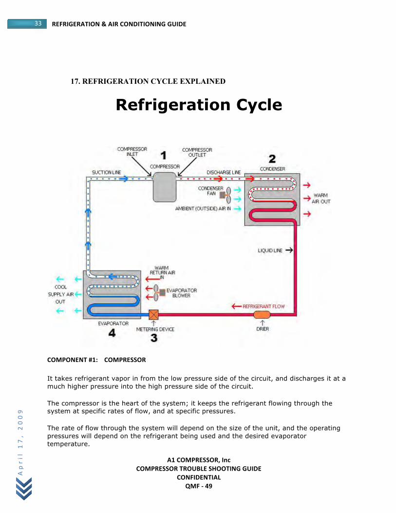
COMPONENT #1: COMPRESSOR
It takes refrigerant vapor in from the low pressure side of the circuit, and discharges it at a much higher pressure into the high pressure side of the circuit.
The compressor is the heart of the system; it keeps the refrigerant flowing through the system at specific rates of flow, and at specific pressures.
The rate of flow through the system will depend on the size of the unit, and the operating pressures will depend on the refrigerant being used and the desired evaporator temperature.
A1 COMPRESSOR, Inc COMPRESSOR TROUBLE SHOOTING GUIDE
CONFIDENTIAL QMF -‐ 49
34 REFRIGERATION & AIR CONDITIONING GUIDE April
17,
2009
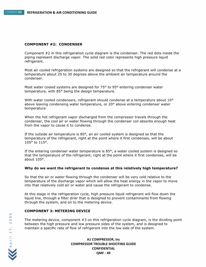
COMPONENT #2: CONDENSER
Component #2 in this refrigeration cycle diagram is the condenser. The red dots inside the piping represent discharge vapor. The solid red color represents high pressure liquid refrigerant.
Most air cooled refrigeration systems are designed so that the refrigerant will condense at a temperature about 25 to 30 degrees above the ambient air temperature around the condenser.
Most water cooled systems are designed for 75° to 95° entering condenser water temperature, with 85° being the design temperature.
With water cooled condensers, refrigerant should condense at a temperature about 10° above leaving condensing water temperature, or 20° above entering condenser water temperature.
When the hot refrigerant vapor discharged from the compressor travels through the condenser, the cool air or water flowing through the condenser coil absorbs enough heat from the vapor to cause it to condense.
If the outside air temperature is 80°, an air cooled system is designed so that the temperature of the refrigerant, right at the point where it first condenses, will be about 105° to 115°.
If the entering condenser water temperature is 85°, a water cooled system is designed so that the temperature of the refrigerant, right at the point where it first condenses, will be about 105°.
Why do we want the refrigerant to condense at this relatively high temperature?
So that the air or water flowing through the condenser will be very cold relative to the temperature of the discharge vapor which will allow the heat energy in the vapor to move into that relatively cold air or water and cause the refrigerant to condense.
At this stage in the refrigeration cycle, high pressure liquid refrigerant will flow down the liquid line, through a filter drier that is designed to prevent contaminants from flowing through the system, and on to the metering device.
COMPONENT 3: METERING DEVICE
The metering device, component #3 on this refrigeration cycle diagram, is the dividing point between the high pressure and low pressure sides of the system, and is designed to maintain a specific rate of flow of refrigerant into the low side of the system.
A1 COMPRESSOR, Inc COMPRESSOR TROUBLE SHOOTING GUIDE
CONFIDENTIAL QMF -‐ 49
35 REFRIGERATION & AIR CONDITIONING GUIDE April
17,
2009
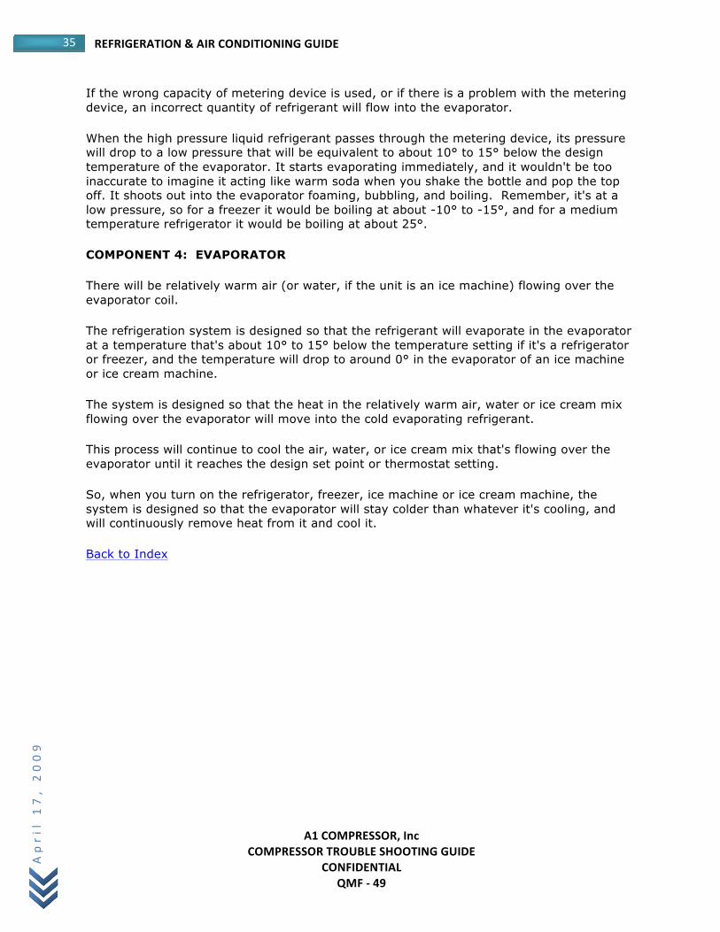
If the wrong capacity of metering device is used, or if there is a problem with the metering device, an incorrect quantity of refrigerant will flow into the evaporator.
When the high pressure liquid refrigerant passes through the metering device, its pressure will drop to a low pressure that will be equivalent to about 10° to 15° below the design temperature of the evaporator. It starts evaporating immediately, and it wouldn't be too inaccurate to imagine it acting like warm soda when you shake the bottle and pop the top off. It shoots out into the evaporator foaming, bubbling, and boiling. Remember, it's at a low pressure, so for a freezer it would be boiling at about -10° to -15°, and for a medium temperature refrigerator it would be boiling at about 25°.
COMPONENT 4: EVAPORATOR
There will be relatively warm air (or water, if the unit is an ice machine) flowing over the evaporator coil.
The refrigeration system is designed so that the refrigerant will evaporate in the evaporator at a temperature that's about 10° to 15° below the temperature setting if it's a refrigerator or freezer, and the temperature will drop to around 0° in the evaporator of an ice machine or ice cream machine.
The system is designed so that the heat in the relatively warm air, water or ice cream mix flowing over the evaporator will move into the cold evaporating refrigerant.
This process will continue to cool the air, water, or ice cream mix that's flowing over the evaporator until it reaches the design set point or thermostat setting.
So, when you turn on the refrigerator, freezer, ice machine or ice cream machine, the system is designed so that the evaporator will stay colder than whatever it's cooling, and will continuously remove heat from it and cool it.
Back to Index
A1 COMPRESSOR, Inc COMPRESSOR TROUBLE SHOOTING GUIDE
CONFIDENTIAL QMF -‐ 49
36 REFRIGERATION & AIR CONDITIONING GUIDE April
17,
2009
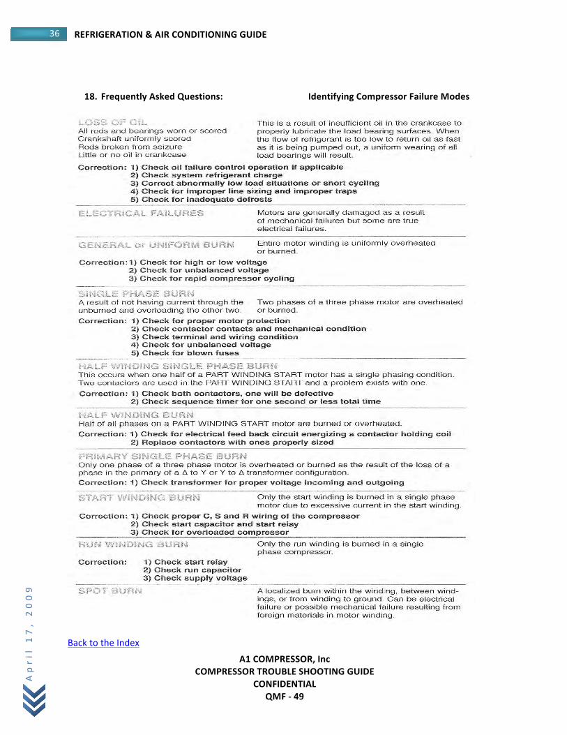
18. Frequently Asked Questions: Identifying Compressor Failure Modes
Back to the Index
A1 COMPRESSOR, Inc COMPRESSOR TROUBLE SHOOTING GUIDE
CONFIDENTIAL QMF -‐ 49
37 REFRIGERATION & AIR CONDITIONING GUIDE April
17,
2009
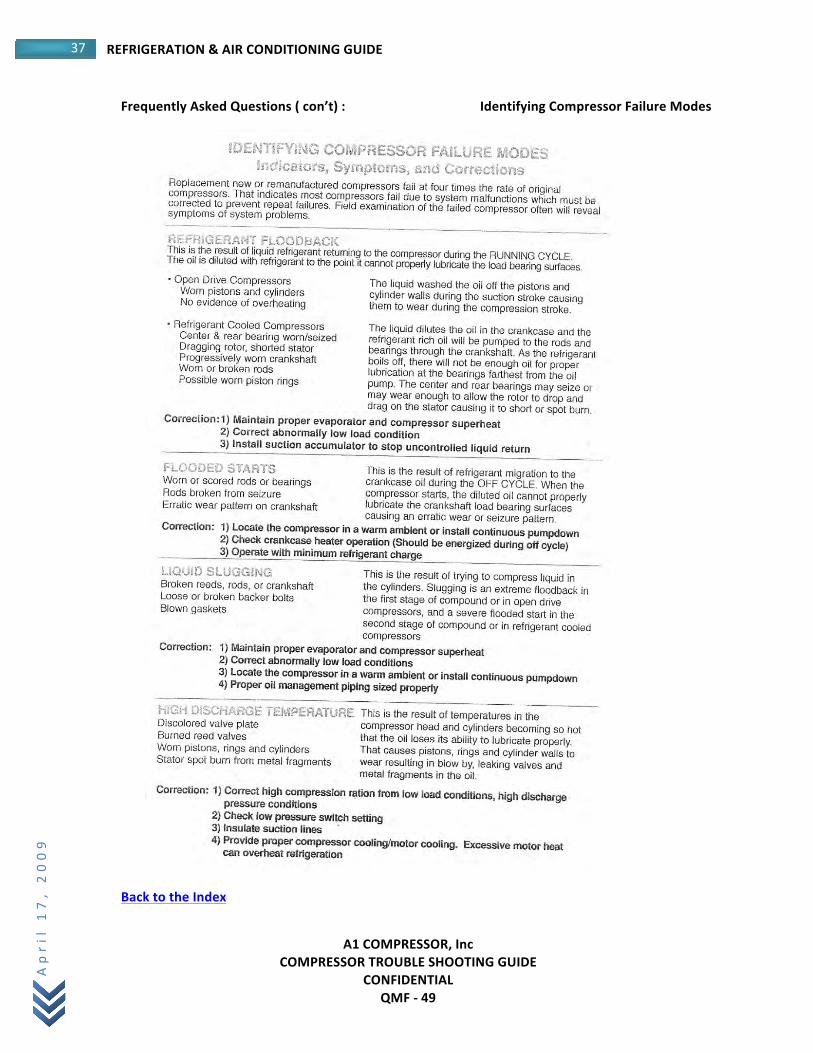
Frequently Asked Questions ( con’t) : Identifying Compressor Failure Modes
Back to the Index
A1 COMPRESSOR, Inc COMPRESSOR TROUBLE SHOOTING GUIDE
CONFIDENTIAL QMF -‐ 49
38 REFRIGERATION & AIR CONDITIONING GUIDE April
17,
2009
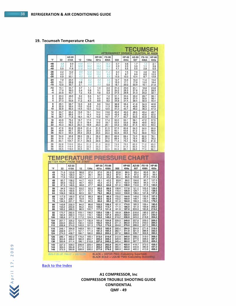
19. Tecumseh Temperature Chart
Back to the Index
A1 COMPRESSOR, Inc COMPRESSOR TROUBLE SHOOTING GUIDE
CONFIDENTIAL QMF -‐ 49
39 REFRIGERATION & AIR CONDITIONING GUIDE April
17,
2009
Tecumseh Temperature Chart ( con’t)
HOW TO SET SUPER HEAT When the room or box has reached its desired temperature take the temperature of the Suction Line near the compressor then convert the Suction Pressure over to temperature ( see chart) and subtract it from the Suction Line temperature. The difference is your SUPER HEAT. A1 recommends 15 degF to 20 degF. If it is too low, close off on the Expansion Valve. If it is too HIGH, open up on the Expansion Valve. EXAMPLE: R-‐22 , 70 LBS Suction Line Temperature: 61 degF Suction Line Pressure:: 41 deg F SUPER HEAT: 20 deg F Back to the Index
A1 COMPRESSOR, Inc COMPRESSOR TROUBLE SHOOTING GUIDE
CONFIDENTIAL QMF -‐ 49
40 REFRIGERATION & AIR CONDITIONING GUIDE April
17,
2009
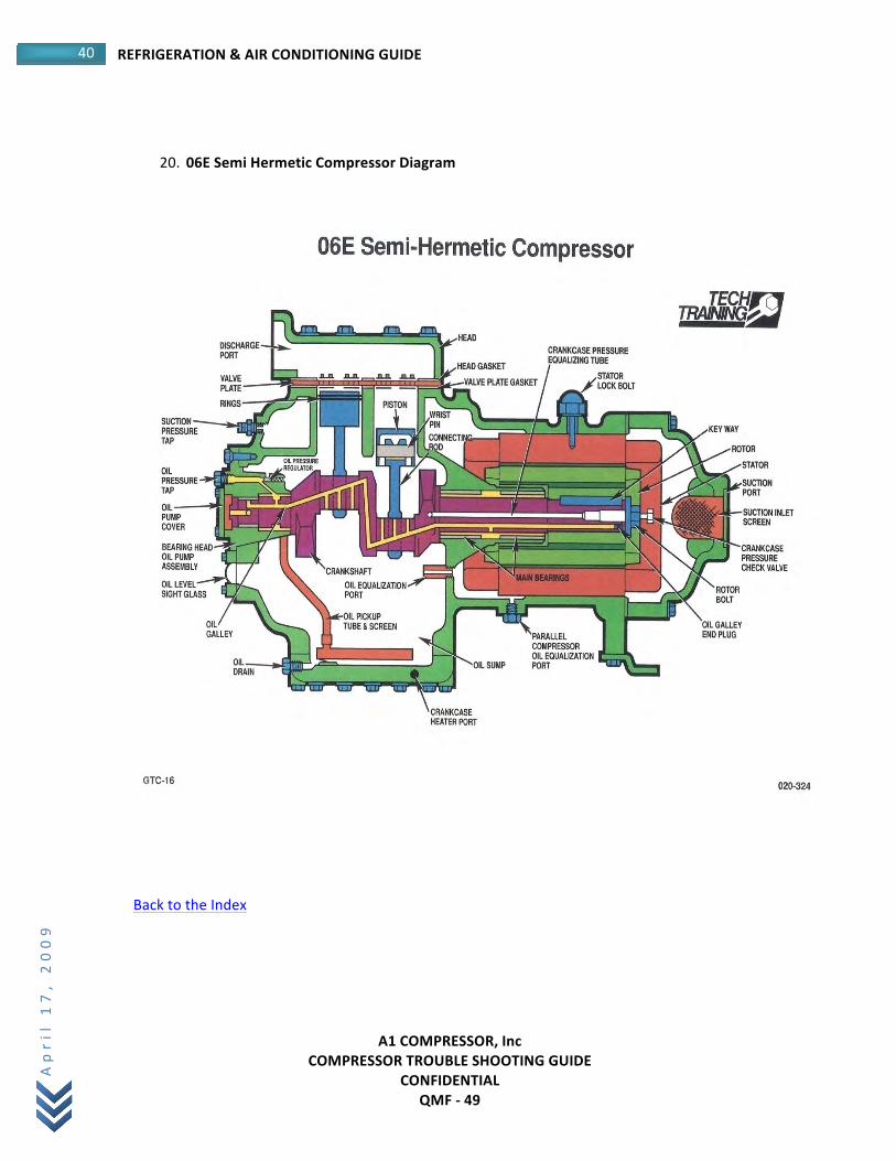
20. 06E Semi Hermetic Compressor Diagram
Back to the Index
A1 COMPRESSOR, Inc COMPRESSOR TROUBLE SHOOTING GUIDE
CONFIDENTIAL QMF -‐ 49
41 REFRIGERATION & AIR CONDITIONING GUIDE April
17,
2009
COMPRESSOR SERIAL NUMBER _____________________________________
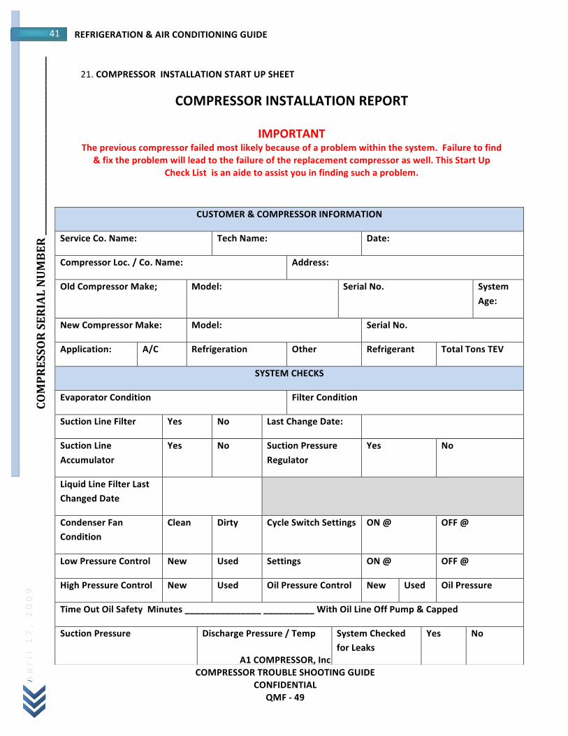
21. COMPRESSOR INSTALLATION START UP SHEET
COMPRESSOR INSTALLATION REPORT
IMPORTANT The previous compressor failed most likely because of a problem within the system. Failure to find
& fix the problem will lead to the failure of the replacement compressor as well. This Start Up Check List is an aide to assist you in finding such a problem.
CUSTOMER & COMPRESSOR INFORMATION
Service Co. Name: Tech Name: Date:
Compressor Loc. / Co. Name: Address:
Old Compressor Make; Model: Serial No. System Age:
New Compressor Make: Model: Serial No.
Application: A/C Refrigeration Other Refrigerant Total Tons TEV
SYSTEM CHECKS
Evaporator Condition Filter Condition
Suction Line Filter Yes No Last Change Date:
Suction Line Accumulator
Yes No Suction Pressure Regulator
Yes No
Liquid Line Filter Last Changed Date
Condenser Fan Condition
Clean Dirty Cycle Switch Settings ON @ OFF @
Low Pressure Control New Used Settings ON @ OFF @
High Pressure Control New Used Oil Pressure Control New Used Oil Pressure
Time Out Oil Safety Minutes _______________ __________ With Oil Line Off Pump & Capped
Suction Pressure Discharge Pressure / Temp System Checked for Leaks
Yes No
A1 COMPRESSOR, Inc COMPRESSOR TROUBLE SHOOTING GUIDE
CONFIDENTIAL QMF -‐ 49
42 REFRIGERATION & AIR CONDITIONING GUIDE April
17,
2009
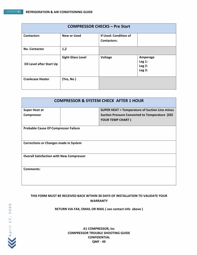
COMPRESSOR CHECKS – Pre Start
Contactors New or Used If Used: Condition of Contactors:
No. Contactor 1,2
Oil Level after Start Up
Sight Glass Level Voltage Amperage Leg 1: Leg 2: Leg 3:
Crankcase Heater (Yes, No )
COMPRESSOR & SYSTEM CHECK AFTER 1 HOUR
Super Heat at Compressor
SUPER HEAT = Temperature of Suction Line minus Suction Pressure Converted to Temperature (SEE YOUR TEMP CHART )
Probable Cause Of Compressor Failure
Corrections or Changes made in System
Overall Satisfaction with New Compressor
Comments:
THIS FORM MUST BE RECEIVED BACK WTIHIN 30 DAYS OF INSTALLATION TO VALIDATE YOUR WARRANTY
RETURN VIA FAX, EMAIL OR MAIL ( see contact info above )


