Instruction Manual EN Compressors ROLLAIR ® Type 15 (X-XT) , 20-25-30 (M-X-MT-XT) 40 (ME-XE-MET-XET), 20-30 (V-VT) 62 305 052 12 ed00 GUARANTEE The ROLLAIR ® compressor is guaranteed for 12 months from date of commissioning or a maximum of 18 months from date of manufacture (which ever occurs first). The guarantee will only be applicable subject to strict observation of the installation conditions and the maintenance operations specified in these operating instructions. The guarantee is limited to replacing parts that are recognised as defective by our services. NOTE This instructions manual complies with the stipulation of European 98/37/EC concerning machine safety and is valid for machines carrying the CE label. ROLLAIR ® 30M ROLLAIR ® 30XT
Transcript
Instruction Manual ENCompressors
ROLLAIR®
Type 15 (X-XT), 20-25-30 (M-X-MT-XT)40 (ME-XE-MET-XET), 20-30 (V-VT)
62 305 052 12 ed00
GUARANTEEThe ROLLAIR® compressor is guaranteed for 12 months from date of commissioning
or a maximum of 18 months from date of manufacture (which ever occurs first).
The guarantee will only be applicable subject to strict observation of the installation conditionsand the maintenance operations specified in these operating instructions.
The guarantee is limited to replacing parts that are recognised as defective by our services.
NOTE
This instructions manual complies with the stipulation of European 98/37/EC concerning machine safety and is valid for machines carrying the CE label.
ROLLAIR® 30M ROLLAIR® 30XT
03/06Page 2
Worthington-Creyssensac62 305 052 12
The ROLLAIR® should never be operated beyond its capabilitiesor in any way which does not comply with the instructions contained
in this operating and maintenance guide.
Worthington-Creyssensac will decline any responsibilityif these instructions are not respected.
This equipment has been factory tested and satisfies normaloperating conditions: they must not be exceeded
as this would place the machine under abnormal stress and effort.
INSTALLATION INSTRUCTIONSFor the guarantee to be valid, the unit must be assembled in covered
premises with temperatures not exceeding :
Mini: + 4 °C (frost free)
Maxi: + 40 °CYou must also have:
1 meter space around the compressor-
low ventilation (fresh air) proportionate to the ventilation flow necessary for the machine and protectedfrom any infiltration of humidity (splashes of water during bad weather) and all pollution
-top insulation or extraction to ensure reversal of the flow of warm air and evacuation of the heat to
outside the equipment room-
a link from the condensation water evacuation pipe to the drain discharger-
in dusty environment, pre-filtering the room's air intake and a special filteron the machine's ventilation inlets
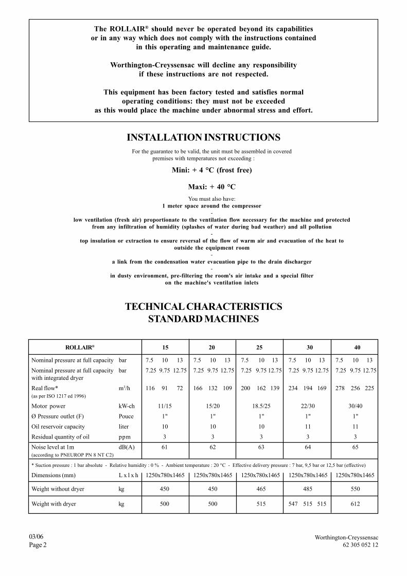
TECHNICAL CHARACTERISTICSSTANDARD MACHINES
ROLLAIR® 15 20 25 30 40
Nominal pressure at full capacity bar 7.5 10 13 7.5 10 13 7.5 10 13 7.5 10 13 7.5 10 13
Nominal pressure at full capacity bar 7.25 9.75 12.75 7.25 9.75 12.75 7.25 9.75 12.75 7.25 9.75 12.75 7.25 9.75 12.75with integrated dryer
Real flow* m3/h 116 91 72 166 132 109 200 162 139 234 194 169 278 256 225(as per ISO 1217 ed 1996)
Motor power kW-ch 11/15 15/20 18.5/25 22/30 30/40
Ø Pressure outlet (F) Pouce 1" 1" 1" 1" 1"
Oil reservoir capacity liter 10 10 10 11 11
Residual quantity of oil ppm 3 3 3 3 3
Noise level at 1m dB(A) 61 62 63 64 65(according to PNEUROP PN 8 NT C2)
* Suction pressure : 1 bar absolute - Relative humidity : 0 % - Ambient temperature : 20 °C - Effective delivery pressure : 7 bar, 9,5 bar or 12,5 bar (effective)
Dimensions (mm) L x l x h 1250x780x1465 1250x780x1465 1250x780x1465 1250x780x1465 1250x780x1465
Weight without dryer kg 450 450 465 485 550
Weight with dryer kg 500 500 515 547 515 515 612
Worthington-Creyssensac62 305 052 12
03/06Page 3
ROLLAIR® Type 15 20 25 30 40
Motor power (kW) 11 15 18.5 22 30
Mains voltage 220/230/240 Volt / 3 / 50 Hz
Nominal intensity (230V) 47 64 78 92 115Power supply cable H 07 4 x 6 4 x 10 4 x 16 4 x 25 4 x 35Section mm2 (L=10m maximum)Upstream fuses (Type aM) 63 100 100 125 160
Mains voltage 380/400/415 Volt / 3 / 50 Hz
Nominal intensity (400V) 27 37 45 53 66Power supply cable H 07 4 x 6 4 x 6 4 x 10 4 x 10 4 x 16Section mm2 (L=10m maximum)Upstream fuses (Type aM) 40 50 63 80 80
Connection of the electric plate to an external control box
• Install an RC filter on the KM1 coil.• Install an RC filter on the KM2 coil.• All connections between external parts and the compressor must be carried out using a shielded cable, which must be earthed at one of its ends.
WARNING: the operation connection cables between the different elements must never follow the same path as the existing powercords. A separate installation from the power cords must be carried out.
• Install an RC filter on all the relay coils of the external operation units.
TECHNICAL CHARACTERISTICSVARIABLE SPEED MACHINES
ROLLAIR® 20V 30V
Nominal pressure at full capacity bar 4 7 9.5 4 7 9.5
Nominal pressure at full capacity bar 3.75 6.75 9.25 3.75 6.75 9.25with integrated dryer
Real flow* m3/h 190 169 145 235 234 209(as per ISO 1217 ed 1996)
Noise level at 1m dB(A) from 58 to 68 from 58 to 68(according to PNEUROP PN 8 NT C2) (from 16 to 80Hz) (from 12 to 70Hz)
* Suction pressure : 1 bar absolute - Relative humidity : 0 % - Ambient temperature : 20 °C- Effective delivery pressure : 7 bar, 9,5 bar or 12,5 bar (effective)
Dimensions (mm) L x l x h 1250x780x1645 1250x780x1645
Weight without dryer kg 470 530
Weight with dryer kg 520 592
03/06Page 4
Worthington-Creyssensac62 305 052 12
CONTENTS
Space requirement and installation diagram : ROLLAIR® 15 (X-XT), 20-25-30 (M-X-MT-XT), 40 (ME-XE-MET-XET), 20V-30V ............. 6
Section 1 - Description
A - General .......................................................................................................................................................................................... 7B - Respect of the environment and prevention of pollution ............................................................................................................. 7C - Standard equipment ...................................................................................................................................................................... 7D - Definition of the pictograms ......................................................................................................................................................... 7E - Electronic board ( M-X) ............................................................................................................................................................... 7
Chapter 2 - Installation
A - Handling ........................................................................................................................................................................................ 8B - Room ............................................................................................................................................................................................ 8C - Assembly ...................................................................................................................................................................................... 8D - Air discharge piping ...................................................................................................................................................................... 8E - Condensate drain pipes ................................................................................................................................................................ 8F - Electric cabling .............................................................................................................................................................................. 8
Section 3 - Initial setup
A - Preparation for start-up ................................................................................................................................................................ 9B - First start-up ................................................................................................................................................................................ 9C - Delivery pressure adjustment ....................................................................................................................................................... 9D - Adjustment for in parallel operation with other compressors ................................................................................................... 10E - Safety .......................................................................................................................................................................................... 10
Chapter 4 - Operation
A - Air and oil circuits ....................................................................................................................................................................... 11B - Regulation principles .................................................................................................................................................................. 12
Chapter 5 - Options
A - Level detection bleed valve ......................................................................................................................................................... 13B - Advanced filtration to the compression air inlet ......................................................................................................................... 13C - Pre-filtration panels .................................................................................................................................................................... 14D - Automatic restarting ................................................................................................................................................................... 15E - Remote starting and stopping ..................................................................................................................................................... 15F - Oil re-heating .............................................................................................................................................................................. 15G - Rotation direction indicator - Phase controller ........................................................................................................................... 15H - 4000 hour oil ............................................................................................................................................................................... 16I - "PROGRESSIVE" regulation ...................................................................................................................................................... 16J - High sensitivity pressure switch ................................................................................................................................................ 17K - Centrifugal separator .................................................................................................................................................................. 17
Chapter 6 - Specific information for ROLLAIR® 20V-30V
A - Technical data ............................................................................................................................................................................. 22B - Operation .................................................................................................................................................................................... 24C - Installation .................................................................................................................................................................................. 25D - Start up ....................................................................................................................................................................................... 25E - Maintenance ............................................................................................................................................................................... 25F - Troubles hooting and emergency solutions ................................................................................................................................ 27
Section 8 - Maintenance
A - Oil change and oil level ............................................................................................................................................................... 28B - Air filter ...................................................................................................................................................................................... 29C - Turbine ....................................................................................................................................................................................... 29D - Oil and air cooler ......................................................................................................................................................................... 29E - De-oiling cartridge ....................................................................................................................................................................... 30F - Oil return pipe ............................................................................................................................................................................ 30G - Draining condensation water ...................................................................................................................................................... 30H - Temperature safety tests ............................................................................................................................................................ 30I - Refastening electric connections ................................................................................................................................................. 30J - Decommissioning the compressor at the end of its useful life ................................................................................................... 30
Section 9 - Operating incidents
A - Main incidents ............................................................................................................................................................................ 31
Worthington-Creyssensac62 305 052 00
03/06Page 6
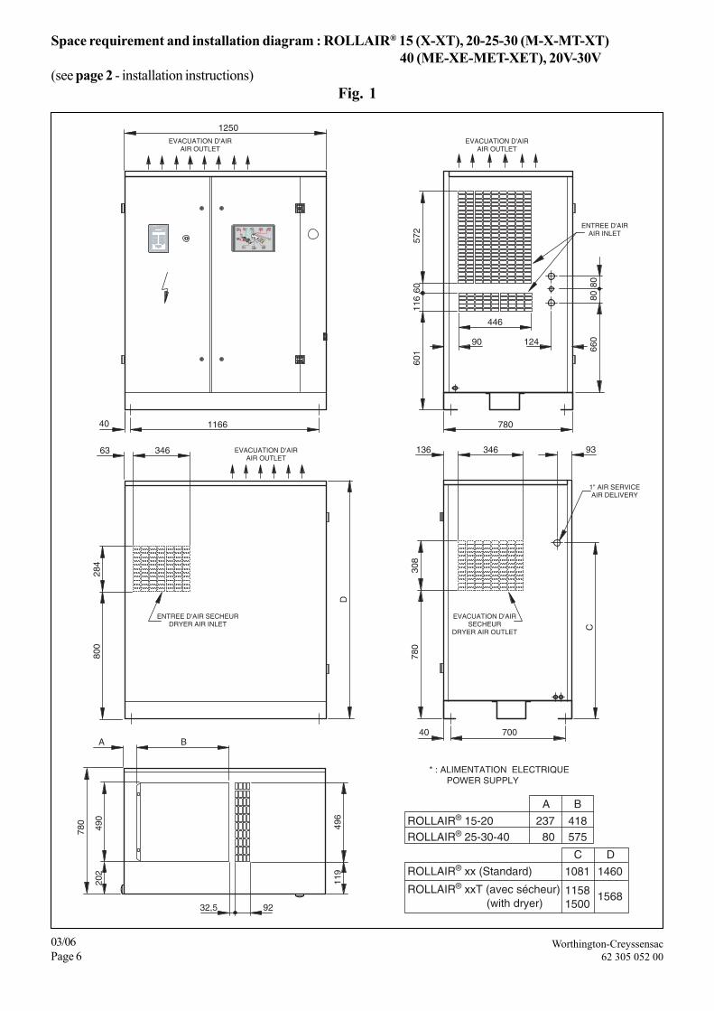
Space requirement and installation diagram : ROLLAIR® 15 (X-XT), 20-25-30 (M-X-MT-XT)40 (ME-XE-MET-XET), 20V-30V
(see page 2 - installation instructions)Fig. 1
F2 F3
F4
ROLLAIR® xx (Standard)
ROLLAIR® 25-30-40
ROLLAIR® xxT (avec sécheur)(with dryer)
ROLLAIR® 15-20
A B
23780
418575
* : ALIMENTATION ELECTRIQUE POWER SUPPLY
EVACUATION D'AIRAIR OUTLET
EVACUATION D'AIRAIR OUTLET
EVACUATION D'AIRSECHEUR
DRYER AIR OUTLET
ENTREE D'AIR SECHEURDRYER AIR INLET
ENTREE D'AIRAIR INLET
1" AIR SERVICEAIR DELIVERY
1166 780
32,5 92
446
90 124
BA
1250
34663 346136
496
119
93
C
780
780
490
202
70040
4030
8
EVACUATION D'AIRAIR OUTLET
660
D
8080
601
800
284
572
116
60
C
1081
11581500
D
1460
1568
Worthington-Creyssensac62 305 052 12
03/06Page 7
Section 1 - DescriptionA - GeneralThe Worthington-Creyssensac "ROLLAIR®" compressor compri-ses a compressed air unit in the form of a self contained, completeand fully tested assembly, driven by an electric motor and enclosedin an acoustic casing, necessary for proper cooling of the assembly.
It is an oil-cooled, single stage, helical screw-type compressor.There is a transversally mounted reservoir for pre-separating andstoring oil and air. The air is then de-oiled by means of a de-oilingcartridge.
Both the compressor and the motor are directly fixed on the frameby anti-vibration mounts.
B - Respect of the environment andprevention of pollution
1 - Maintenance of the machineMake sure that the used components of the machine (waste oil,oil and air filters, oil separators, etc...) are disposed of accordingto national and local regulations.
2 - Condensate bleed pipeMake sure that the condensates (water, oil) are drained and treatedaccording to national and local regulations.
3 - End of life of the machineMake sure that the machine as a whole is disposed of according tonational and local regulations ( See E Chap. 7 and J Chap. 8 ).
C - Standard equipmentIn its standard version, the covered unit includes:
- Operating components:1. A twin-screw compressor.2. An electric motor: 3,000 rpm, short-circuit rotor, voltage
230/400 V or 400/690 V according to type.3. Star-delta starting.4. A direct drive or gearbox drive .5. An air / oil reservoir complying to current legislation (Euro-
pean Directive for simple pressure vessels no. 87/404) whichwas standardised by an approved regulatory body andbearing the CE mark.
6. "start - stop" flow rate control by suction closing.7. A lubrication system using the differential pressure of the
circuit, which avoids the need for an oil pump.8. An oil separation system by means of a de-oiling cartridge.9. A calorie draining system : oil and compressed air radiator
with forced ventilation.10. A dry-type air filter.11. An oil filter.12. A command and control electronic board.
- Safety devices:
1. A safety valve mounted on the oil reservoir.2. An thermal protection device for the motor, situated in the
starting box, to protect the motor from excessive over-load.3. An air temperature sensor that stops the compressor when
the temperature rises abnormally or during an oil coolingdefect.
4. A pressure sensor that stops the compressor in the event ofan excessive rise in pressure (X and V).
- Control devices:
1. A minimum pressure valve located at the oil tank outlet,just beyond the oil separator, which guarantees minimumpressure in the lubrication circuit.
2. Automatic draining allowing the unit to be exposed to theatmosphere when stopping to thus ensure empty start upwhich relieves the motor,
3. An oil level gauge on the front panel (see fig. 19),4. An electronic controller including:
– a control keyboard,– the main safety and control indications.
5. The compressed air output is regulated by a pressure sensoror pressure switch
The ROLLAIR® compressed air unit has been designed, producedand tested in accordance with the following recommendations,codes and standards :
- machine safety: European Directive 98/37/CE, 91/368/CEE and93/68/CEE.
- pressure vessels: European Directive for simple pressure vesselsn° 87/404/CEE.
- electrical equipment:• electrical equipment: European Directive Low tension 73/23/CEE.• electromagnetic compatibility European Directive: 89/336/
CEE, 92/31/CEE.- performance levels: ISO 1217 : 1996.- noise level : PNEUROP PN 8 NT C2.- European Directive 97/23/EC " Pressure Equipment Directive ".
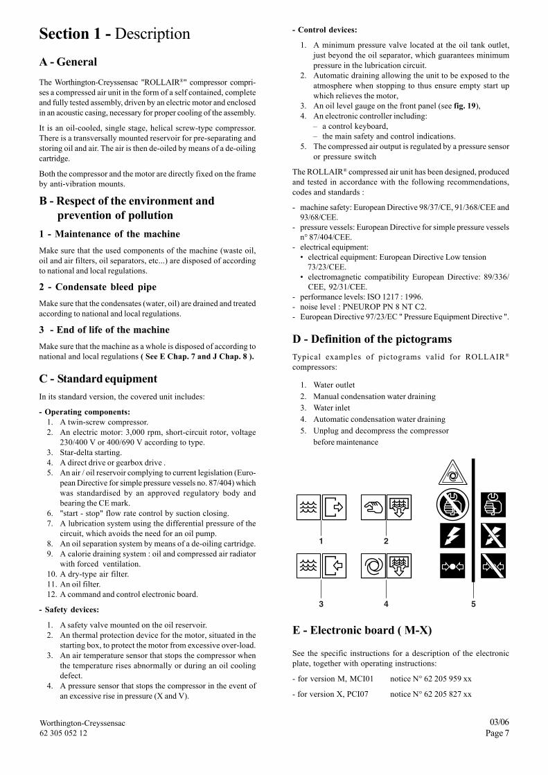
D - Definition of the pictogramsTypical examples of pictograms valid for ROLLAIR®
compressors:
1. Water outlet2. Manual condensation water draining3. Water inlet4. Automatic condensation water draining5. Unplug and decompress the compressor
before maintenance
1 2
3 4 5
E - Electronic board ( M-X)
See the specific instructions for a description of the electronicplate, together with operating instructions:
- for version M, MCI01 notice N° 62 205 959 xx
- for version X, PCI07 notice N° 62 205 827 xx
Worthington-Creyssensac62 305 052 12
03/06Page 8
Chapter 2 - InstallationA - Handling
The ROLLAIR® must always be handled with care. It may belifted either with a forklift truck or by means of a travelling crane.In the latter case, precautions must be taken so as not to damagethe unit's cowling.
B - Room
The ROLLAIR® is designed to operate in a frost-free environment,supplied with air at a temperature of no more than 40° C. Thepremises must be well-aired and as close as possible to the placewhere the compressed air is used. A space must be left around theunit, for cleaning and maintenance purposes. It is very importantfor the compressor to have an abundant supply of fresh air.(see page 2).
If operating the compressor causes the ambient temperature torise above 40 °C, the warm air leaving the radiator must be dischargeoutside.
COMMENTWhen the atmosphere is contaminated by organic or mineral dust orby corrosive chemical emanations the following precautions must betaken:
1. Provide another air intake as close as possible to the suctionsource of the compressor (this recommendation applies ifthe only room available is excessively humid).
2. Use an additional filter for the unit's air supply(See Options Chapter).
C - Assembly
Put the unit on a stable surface. The ROLLAIR® does not needfoundations. Any flat surface that can support its weight will besufficient (industrial floor).
D - Air discharge piping
The diameter of the piping for the air network must at least beequal to 1" of the gas piping. Current legislation requires theinstallation of a valve which can be locked in a closed position atthe outlet of the compressor and connected to the compressorby a pipe union or flexible hose so as to isolate it during servicing.
E - Condensate drain pipes
A separator may be included inside the unit (See Chapter 5 - K)to eliminate condensates in the final cooler outlet and stopcondensates in pipelines from returning to the compressor.Connect the exhaust pipe to a condensate collector.
Version X and T : a separator with automatic draining by electro-valve is placed inside the unit to eliminate condensation waterleaving the final cooler and stop condensation water from returningfrom the piping to the compressor.
F - Electric cabling
Each ROLLAIR® supplied is cabled for 220/230/240 V or 380/400/415 V .
NEVER OPERATE THE ROLLAIR® ON A VOLTAGE OTHERTHAN THAT SHOWN ON THE ELECTRIC CABINET.
The electric current supply to the ROLLAIR® must comply withthe following table :
Type of cable to be used : H07 RNFPower cable size
(for a maximum 10-metre length)
VOLTAGEROLLAIR® Type
220/230/240 V 380/400/415 V15 4 x 6 mm2 4 x 6 mm2
20 4 x 10 mm2 4 x 6 mm2
25 4 x 16 mm2 4 x 10 mm2
30 4 x 25 mm2 4 x 10 mm2
40 4 x 35 mm2 4 x 16 mm2
SAFETY REGULATIONS
It should be remembered that safety regulations require :
• An earth socket to be used.• A manual isolating switch, cutting all three phases ; this switch
must be clearly visible near the ROLLAIR® unit.• The electric current must be cut whenever maintenance work is
carried out on the machine (except for pressurized oil change ).
Fuses to be used forthe isolating switch (AM type)
Section 3 - Initial setupA - Preparation for start-upBefore starting up the unit for the first time, the operator must befamiliar with the different parts of the machine. The main partswhich should be examined are indicated in the diagrams.
IMPORTANTBefore start up, make sure that transport red wedges have beeneffectively removed.
ATTENTIONLe circuit de puissance devra être coupé pour tout réglage exécutésur l’équipement électrique ou pour éviter tout démarrage accidentel.
Before start-up, check the following points :
1 - Make sure that the unit is properly earthed.2 - Check the oil level in the tank.
NOTE : the tank has been filled with suitable oil in thefactory. See Chapter 5 - A for the quality of oil to be usedor for oil renewal conditions.
3 - Make sure the oil change valve is properly closed.
ATTENTIONThe oil filler cap, the oil change valve and plugs must alwaysremain closed during operation and never be opened before thesystem has been completely vented to atmospheric pressure(except pressurized oil change : see Chapter 5 -A).
Fig. 2Delivery pressure gauge
B - First start-upCheck the voltage between the three phases before using the unitfor the first time.Check the direction of rotation (following the arrow on the couplinghousing (item. 1 - Fig. 3)) by pressing the "Start" button, followedimmediately by the emergency stop. If it does not spin in the rightdirection reverse two stages of the power cord. When it rotates inthe correct direction, the oil level (Fig.19) should drop after 4 or5 seconds of operation.
Fig. 3
It is very important to remember to check the direction of rotationof the fan (shown by an arrow on the fan (item. 1 - Fig. 4)).
Fig. 4
1 - Press the ON button, the motor starts up.2 - Leave it running for a few minutes with the discharge valve
slightly open to observe the compressor under load. Ensurethat there are no leaks. Reblock the connectors if necessary.
3. Press the STOP button. The motor stops and the unit isautomatically placed at atmospheric pressure.
C - Delivery pressure adjustmentThe group is adjusted in the factory for MAXIMUM pressure(at full flow when leaving the central unit) of 7.5, 10 or 13 bar(7.25, 9.75, 12.75 bar for versions T with a built-in dryer) dependingon the type of device. To adjust the surge pressure settings, closethe valve, but not completely and engage the pressure switch byunscrewing the setting screw to lower the pressure and by screwingit to make it go up (Fig. 2).
Deflectionadjustmentscrew
Pressureadjustmentscrew
7.5-10 bar
13 bar
Pressureadjustment
Deflectionadjustment
Deflectionadjustmentscrew
Pressureadjustmentscrew
1
1
Worthington-Creyssensac62 305 052 12
03/06Page 10
D - Adjustment for in parallel operationwith other compressors
If the ROLLAIR® has to operate in parallel with other ROLLAIRS®,or similar compressors, the discharge pipes can be connected together.
If the ROLLAIR® has to operate in parallel with one or severalalternative compressors, an air tank common to the alternativecompressors is essential. The impulses emitted by the alternativecompressors would seriously damage the non-return valve, theROLLAIR® deoiling element and disturb system regulation. Whenthe rotary compressor operates in parallel with an alternativecompressor, the adjustments on the latter will have to be adjustedso that the rotary compressor carries the basic load. This will resultin more economic operation.
E - SafetyThe oil used for cooling the machine is a liquid combustible underthe effect of strong heat. In case of fire in the machine, it is essentialto respect the regulatory measures on the compressor. The type offire in a compressor is defined as "class B" and in presence of a liveelectrical conductor, it is recommended to use a CO2 extinguisherfunctioning by "smothering" (starvation of oxygen) while observingthe user instructions applicable to the model.
Worthington-Creyssensac62 305 052 12
03/06Page 11
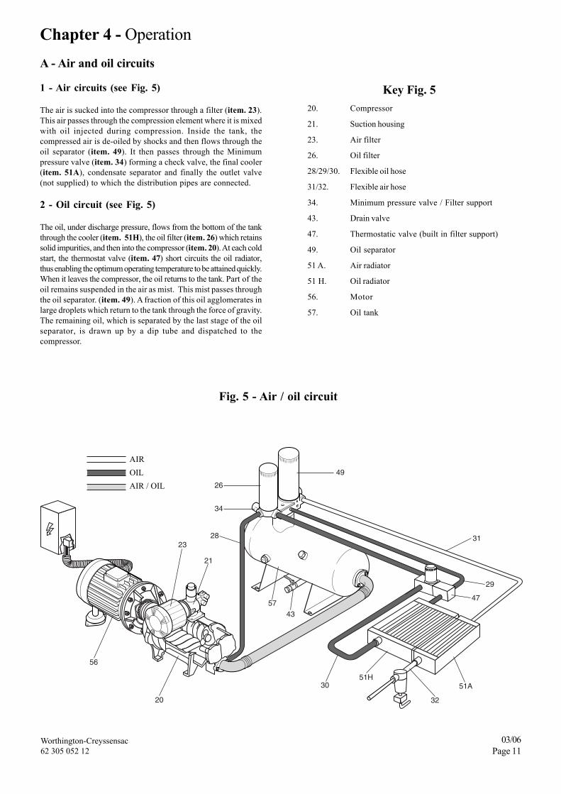
Chapter 4 - OperationA - Air and oil circuits
1 - Air circuits (see Fig. 5)
The air is sucked into the compressor through a filter (item. 23).This air passes through the compression element where it is mixedwith oil injected during compression. Inside the tank, thecompressed air is de-oiled by shocks and then flows through theoil separator (item. 49). It then passes through the Minimumpressure valve (item. 34) forming a check valve, the final cooler(item. 51A), condensate separator and finally the outlet valve(not supplied) to which the distribution pipes are connected.
2 - Oil circuit (see Fig. 5)
The oil, under discharge pressure, flows from the bottom of the tankthrough the cooler (item. 51H), the oil filter (item. 26) which retainssolid impurities, and then into the compressor (item. 20). At each coldstart, the thermostat valve (item. 47) short circuits the oil radiator,thus enabling the optimum operating temperature to be attained quickly.When it leaves the compressor, the oil returns to the tank. Part of theoil remains suspended in the air as mist. This mist passes throughthe oil separator. (item. 49). A fraction of this oil agglomerates inlarge droplets which return to the tank through the force of gravity.The remaining oil, which is separated by the last stage of the oilseparator, is drawn up by a dip tube and dispatched to thecompressor.
Fig. 5 - Air / oil circuit
Key Fig. 520. Compressor
21. Suction housing
23. Air filter
26. Oil filter
28/29/30. Flexible oil hose
31/32. Flexible air hose
34. Minimum pressure valve / Filter support
43. Drain valve
47. Thermostatic valve (built in filter support)
49. Oil separator
51 A. Air radiator
51 H. Oil radiator
56. Motor
57. Oil tank
20
23
21
57
43
56
28
26
34
29
47
31
49
30
32
51A51H
AIROILAIR / OIL
Worthington-Creyssensac62 305 052 12
03/06Page 12
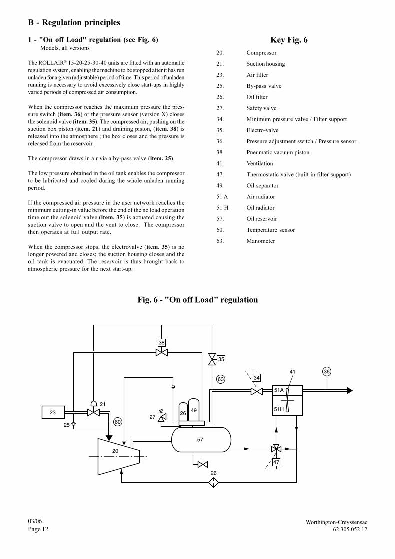
B - Regulation principles
1 - "On off Load" regulation (see Fig. 6)Models, all versions
The ROLLAIR® 15-20-25-30-40 units are fitted with an automaticregulation system, enabling the machine to be stopped after it has rununladen for a given (adjustable) period of time. This period of unladenrunning is necessary to avoid excessively close start-ups in highlyvaried periods of compressed air consumption.
When the compressor reaches the maximum pressure the pres-sure switch (item. 36) or the pressure sensor (version X) closesthe solenoid valve (item. 35). The compressed air, pushing on thesuction box piston (item. 21) and draining piston, (item. 38) isreleased into the atmosphere ; the box closes and the pressure isreleased from the reservoir.
The compressor draws in air via a by-pass valve (item. 25).
The low pressure obtained in the oil tank enables the compressorto be lubricated and cooled during the whole unladen runningperiod.
If the compressed air pressure in the user network reaches theminimum cutting-in value before the end of the no load operationtime out the solenoid valve (item. 35) is actuated causing thesuction valve to open and the vent to close. The compressorthen operates at full output rate.
When the compressor stops, the electrovalve (item. 35) is nolonger powered and closes; the suction housing closes and theoil tank is evacuated. The reservoir is thus brought back toatmospheric pressure for the next start-up.
The BEKOMAT type level detection bleed valve allows all airconsumption to be avoided while the compressor is not running.
For machines with a built-in dryer, two bleeds may be provided,one upline from the dryer and the other on the dryer bleed
2 - Option overview
- There is no air consumption due to the level detection system : aninductive sensor detects the level of condensation and thus controlsthe opening of the electric bleed valve. A low level of condensation isalso detected in order to close the electric bleed valve and to preventcompressed air from being wasted.
- This type of purge valve does not require any maintenance. Thepurge valve does not require the use of the metallic intake filterthat is usually installed on electronic purge valves to protect thesolenoid valve. The solenoid valve will not be damaged.
- Condensate discharge facilitated as condensates are not dischargedunder pressure facilitating separation of the condensate oil and waterphases.
1
2
3
4
5
6
1 - Condensation intake 4 - Main duct2 - Capacitive sensor 5 - Electric valve3 - Reservoir 6 - Membrane
3 - Technical featuresMaximum capacity of the compressor : 20 m3/minWorking pressure : 0.8 / 16 barOperating pressure : + 1 / + 60°CElectric power supply : 230 / 110 / 24/ …AC socket in the compressor electric cabinet.
B - Advanced filtration to the compressionair inlet
For all information, contact your localWorthington-Creyssensac
Fig. 7
1
2
3
4
5
6
Worthington-Creyssensac62 305 052 12
03/06Page 14
C - Pre-filtration panels
1 - Description
Installing air filtration panels on the ventilation intakes (machineand built-in dryer) guarantees protection of the compressor'sinternal components and an increase in air sucked into thecompression assembly. This option is recommended if the forcedfiltration option is installed (see § B).
2 - Option overview
The pre-filtration panels eliminate 90% of the particles normallyadmitted inside the compressor and considerably decrease internalcontamination of the machine.
The high quality of the ventilation air is also essential for protectinginternal components of the compressor and, more specifically,the motor and the air / air and air / oil exchangers. Clogging in theexchangers creates an increase in temperature, deterioration of thelubricant and the motor becomes overloaded thus increasing theenergy consumed.
The quality of the air drawn in by a compressor is essential. Lowquality air results in the following :• Fast pollution of the oil thus an increase in oil change cycles.• Increased pollution of the air and oil filtering components that
increases the deterioration of the mechanical components in thecompressor, screw block, ...
• Binding of the air / oil separator before 4000 Hours thus anincrease in maintenance cycles and maintenance costs.
Access to the filtering medium is allowed by removal that doesnot require any particular tool. The panel frame can be unlockedmanually in order to clean the medium.
Exceptional longevity of the medium that is quick to take apart.The medium can be scoured by blowing compressed air in thusincreasing the usage term for the filtering medium.
Galvanised steel covered frame.
Non-flammable medium (belonging to fire protection class M1)made of polyester fibres.
Fig. 9
Easy to disassemble for rapid cleaning
Pleated medium on support grid placed downwards in the directionof the airflow.
Support grid
3 - Technical features
FILTER MEDIUM :
Degree of filtration : 90% of the dust emitted is filtered.Total nominal flow : 6 000 m3/hFilter panel number : 2Initial charge loss : 75 PaDimensions : Width : 500 mm
Length : 500 mmThickness : 200 mm
This option may be fitted to a compressor already installed.
2 pannels
Pre-ventilation lock
Disassembly hinges
Fig. 10
Worthington-Creyssensac62 305 052 12
03/06Page 15
D - Automatic restarting
1 - Description
This management system enables the compressor to be restartedautomatically after a power outage.
2 - Option overview
Not available as a standard option in order to prevent any incidentsduring maintenance operations carried out by an unskilled person,this option is proposed in the case when the production ofcompressed air must only be submitted to a minimum of stops.The standard microcut time accepted by MCI 01 is approximately40 ms, the time of PCI07 is 250 ms.However, certain electrical fittings create longer micro cut-offsthat will cause a compressor shut down, then a manual restart.Automatic compressor restarting enables immediate air productionafter a power outage and thus avoids the time lapse required formanual compressor restarting that would mean a fall in pressure inthe air circuit.Particularly used for industries where air production should notbe subject to shut downs that waste the products manufacturedor damage the production equipment.
THIS OPERATION REQUIRES THE CONFIGURATIONOF THE ELECTRONIC BOARD MENUS ACCESSLIMITED TO TECHNICIANS AUTHORISED BY
WORTHINGTON-CREYSSENSAC.
AN INFORMATIVE INSERT MUST BE PLACED ONTHE ELECTRIC CABINET TO WARN THE USER OF
THE RISK THAT THE COMPRESSOR MAYAUTOMATICALLY RESTART AT ANY TIME.
3 - Technical features
This option requires configuration of the electronic plate and ins-tallation of an informative insert on the door of the compressorelectric cabinet.
Whenever the compressor is shut down, the emergencypush-button must be pressed or the electricity isolating
switch thrown.
E - Remote starting and stopping
This option allows the compressor to be remotely started andstopped. However, in all cases, stopping the compressor at themachine itself is essential. If the compressor is shut down from adistance, it may be restarted from a distance as well. On the otherhand, if the compressor is stopped at the machine itself, it cannotbe restarted from a distance.Before carrying out any work on themachine you must check that the machine is switched off locally tocomply with safety requirements (See Notices MCI01, PCI07, DChapter 1)
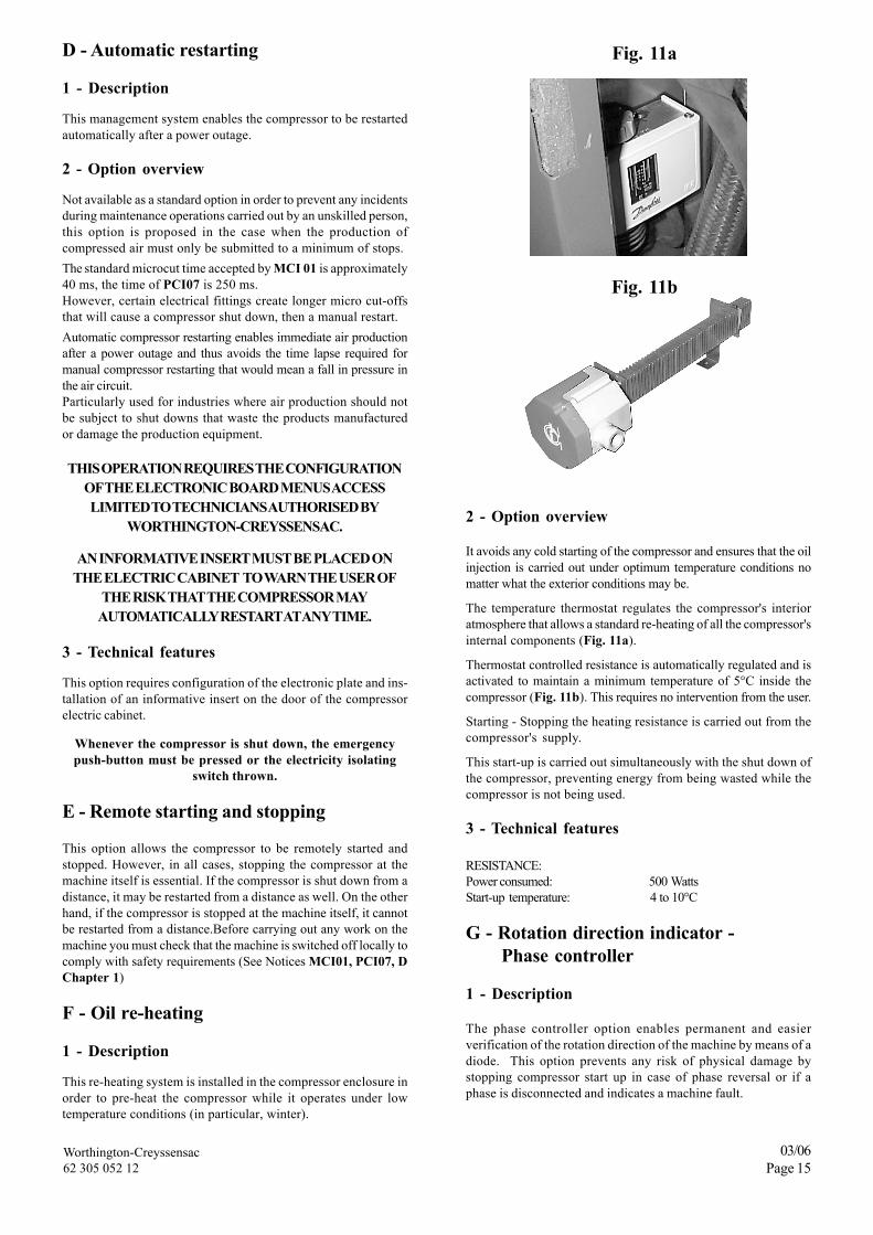
F - Oil re-heating
1 - Description
This re-heating system is installed in the compressor enclosure inorder to pre-heat the compressor while it operates under lowtemperature conditions (in particular, winter).
2 - Option overview
It avoids any cold starting of the compressor and ensures that the oilinjection is carried out under optimum temperature conditions nomatter what the exterior conditions may be.
The temperature thermostat regulates the compressor's interioratmosphere that allows a standard re-heating of all the compressor'sinternal components (Fig. 11a).
Thermostat controlled resistance is automatically regulated and isactivated to maintain a minimum temperature of 5°C inside thecompressor (Fig. 11b). This requires no intervention from the user.
Starting - Stopping the heating resistance is carried out from thecompressor's supply.
This start-up is carried out simultaneously with the shut down ofthe compressor, preventing energy from being wasted while thecompressor is not being used.
3 - Technical features
RESISTANCE:Power consumed: 500 WattsStart-up temperature: 4 to 10°C
G - Rotation direction indicator - Phase controller
1 - Description
The phase controller option enables permanent and easierverification of the rotation direction of the machine by means of adiode. This option prevents any risk of physical damage bystopping compressor start up in case of phase reversal or if aphase is disconnected and indicates a machine fault.
Fig. 11a
Fig. 11b
Worthington-Creyssensac62 305 052 12
03/06Page 16
Fig. 12 - "PROGRESSIVE " regulation (version X)
and controls part closure of the suction box valve (item. 21), sothat the compressor flow is equal to the drawn air flow and thepressure remains constant as long as the air consumption does notchange.IOn changes in air consumption, the overflow pro-gressively controls movement of the suction box valve in or-der tomaintain a constantly equal flow at the end user.
In order to limit the power draw on very low compressed airrequirements, pressure switch (item. 36) is set in order to operatewith no load (nil flow and low pressure in the oil tank) when thecompressed air draw is less than around 30% of the compressormax. flow.
To do this, tripping the pressure switch (item. 36) controls openingof the solenoid valve (item. 35 and item. 58), which trips, on theone hand on total closure of the suction valve and on vacuumizing(item. 38) of the oil tank, in the same way as On/Off regulation.
Key Fig. 1220. Compressor21. Suction housing23. Air filter25. By-pass valve26. Oil filter27. Safety valve34. Minimum pressure valve35/58. Electro-valve36. Pressure adjustment switch38. Pneumatic vacuum piston41. Ventilation44. Drain solenoid valve47. Thermostat valve49 Oil separator51 A Air radiator51 H Oil radiator55. Air / water separator57. Oil reservoir60. Temperature sensor62. Discharger63. Manometer
2 - Option overviewMarking on the motor of the standard machine version identifiesthe motor fan rotation direction during the start up phase. Workon the electric network or the machine may change the rotationdirection and damage the compressor which must be detectedquickly.
H - 4000 hour oil
1 - DescriptionThis is synthetic oil that allows more time between oil changes.
Note : Selecting this option after using a machine that has beenoperated with standard oil requires flushing and an oil change andthe filters should be replaced after 2000 hours of operation.
2 - Option overviewThis oil's qualities enable an oil change and oil filter change to becarried out every 4000 Hours (compared to 2000 Hours) bycarrying out the de-oiler change every 4000 hours.
As a result, maintenance work is carried out less frequently whichleads to operational cost savings for the compressor.
I - "PROGRESSIVE" regulation (see Fig. 12)(Only available with version X)
This method of control can be used to adjust the compressor flowto the compressed air demand, with very little variation of thepressure in the user network.
Nevertheless, it is less economic than the On/Off method,particularly during periods of low compressed air consump-tion.
The compressor operates at full flow (suction box valve (item. 21)fully open) as long as the pressure remains below the back pres-sure regulator pressure (item. 62). If compressed air draw is lessthan the compressor flow at the back pressure regulator pressure,the pressure builds up, the back pressure regulator begins to open
23
20
25
26
63
21
36
22
3435
51A
51H
47
41 62
55
44
58
38
57
2726 49
Worthington-Creyssensac62 305 052 12
03/06Page 17
J - High sensitivity pressure switch(Only available with version M)
1 - Description
This pressure switch is an accessory of the highest sensitivitythat allows it to react to lower pressure differences than the onemounted on the standard version.
2 - Option overview
This pressure switch allows energy to be saved by more preciselymeasuring the pressure in order to initiate draining the machine toa value that is closer to the maximum pressure required.
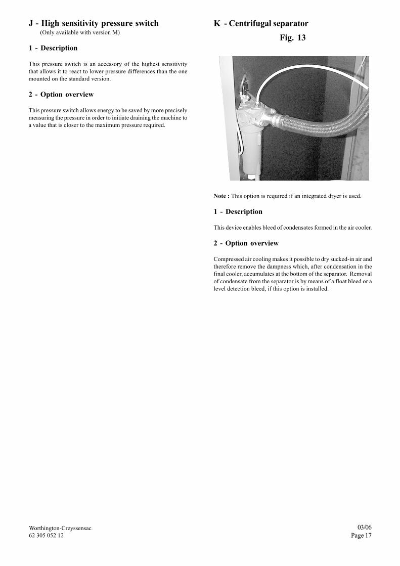
K - Centrifugal separatorFig. 13
Note : This option is required if an integrated dryer is used.
1 - Description
This device enables bleed of condensates formed in the air cooler.
2 - Option overview
Compressed air cooling makes it possible to dry sucked-in air andtherefore remove the dampness which, after condensation in thefinal cooler, accumulates at the bottom of the separator. Removalof condensate from the separator is by means of a float bleed or alevel detection bleed, if this option is installed.
Worthington-Creyssensac62 305 052 12
03/06Page 18
Chapter 6 - Specific information for ROLLAIR® 20V-30VRefer also to the chapters concerning the standard machine.
"ROLLAIR® V" machines are compliant with the Electromagneticcompatibility in industrial environments Standards 50081-2 and50082-2
A - Description (cf Chap. 1)
Standard equipmentA electronic frequency adjusting device replaces the star-deltastarter.A fuse holder section switch completes ROLLAIR® standard'ssafety devices.
B - Safety
For your safety, please respect the instructions carrying thewarning symbols as given below:
SAFETY RULES
The safety rules require:• The presence of an earth socket• The existence of a manual switch cutting-off the three pha-
ses that should be placed visibly near the ROLLAIR®
• It is necessary to cut out the electric current before anyintervention on the machine (except drainage under pres-sure).
= Dangerous voltage
= Attention
ELECTRICAL INSTALLATIONS MUST ONLY BECARRIED OUT BY A SPECIALISED AND COMPETENT
TECHNICIAN
1 - Warning
The internal components and the plates (except theelectrically insulated I/O terminals) are at the mainsvoltage when the inverter is connected to the mains.This voltage is extremely dangerous and can causesevere injuries or even death in case of involuntarycontact.
When the inverter is connected to the mains, theconnection terminals U, V, W of the motor as well as+/- connectors of the braking resistors are under powereven if the motor is not running.
The I/O control terminals are insulated from the mains,the relay outputs can nevertheless be under powereven if the inverter is disconnected. This also appliesto other I/O control terminals even if the X4 switch isin OFF position (Stop).
The inverter has a load circuit of thermally limitedcapacitors. Therefore, it is important to allow minimum5 minutes between two successive power-ons. If thisinstruction is not respected, the switch and the resistorof the load circuit may be damaged.
2 - Safety instructions
No connection work is allowed when the inverter isunder power.
No measurement work is allowed on the inverter whenit is under power.
To undertake any work on the inverter, it is necessaryto disconnect the equipment from the mains. Wait forthe internal ventilation to stop and the indicators to beturned off. Then, wait 5 minutes before opening thecover.
No voltage or insulation verification test is allowed onthe inverter components.
Disconnect the cables from the motor and the inverterbefore taking measurements on them.
Do not touch the integrated circuits, the electrostaticdischarges may damage them.
Before connecting the inverter, make sure that its coveris properly closed.
Make sure that no compensation capacitor of cosinephi is connected to the motor cable.
1
2
3
4
1
2
3
4
5
6
7
8
Worthington-Creyssensac62 305 052 12
03/06Page 19
C - Installation
The "ROLLAIR® V" must be installed away from a transfor-mer or autotransformer.
(see Chapter 2 et 3).
The fuses for the built-in section switch are defined as follows
Mains voltage 380/400/415 Volt / 3 / 50 Hz
Nominal voltage (400V) 39A 52APower supply cable H 07 4 x 10 4 x 25Section mm2 L=10m maxiUpstream fuses (Type aM) 50A 63A
ATTENTIONMotors and drives can only be guaranteed where the supply vol-tage does not exceed the rated voltage by more than 10%.The connection of the power supply to the section switch requiresthe use of properly insulated terminals.
D - Commissioning
1 - Preparation for start-up
(Voir Chapter 3).
ATTENTIONThe power circuit will have to be cut off when adjusting theelectrical equipment or if inadvertent start-up is to be avoided.
Before start-up, check the following points:1 - Ensure that the unit has a suitable earth,2 - Check the oil level in the compressor,
NOTE: the tank was filled in the factory with a suitable oil. SeeChapter 8 - A for the quality of oil to be used and for the oilrenewal conditions.
3 - Check that the drainage valve is properly closed.4 - Make sure that the conveyor assembly's blocking lugs
(compressor) have been removed from the compressorsilentblocks.
ATTENTIONThe oil filler plug, the valve and the drainage plugs have always tobe closed during operation and must never be opened before thesystem has reached atmospheric pressure.
2 - Control of rotation direction on start upThis control must be implemented when the machine is put intooperation for the first time, after any work has been carried out onthe motor and after any changes to the mains supply.
IMPORTANT :
a) Motor - compression unit• Check the direction of rotation (as per the arrow shown on the
sump) by jogging over with the START button.If it is incorrect, swap over two of the motor's phase cablesunder the drive.When rotating in the right direction, the oil level (fig. 19) mustdrop after 4 to 5 seconds of operation.
b) Fan• See Chapter 3 - Initial setup, paragraph B - First start-up,
Figure 4 .
1 - Press the START button so that the motor starts.2 - Allow to rotate for several seconds with the discharge valve
slightly open to observe the compressor at load.3 - Press the STOP button. The motor stops and the plant
automatically returns to atmospheric pressure.
3 - Adjustment of the machine pressure settings(See notice for the VCI07 controller).
The unit is factory pre-set for a given delivery pressure. As anenergy saving measure, it is strongly advised to reduce the pressureto the exact requirement by adjusting the "P charge" setting.
The stop pressure "P discharge" or "P stop" - used when running atless than the minimum flow-rate - must be set to 0.5 bar above thatof the "P charge" setting. In this way, the current used by thecompressor is minimised (see notice VCI07). (Where "P charge" isthe delivery pressure and "P discharge" is the no-load pressure).
Do not set the stop pressure at a level beyond the machine's max P.
4 - Assembly and settings for parallel operationwith other compressors
Pressure for the ROLLAIR® V compressor must be adjusted at avalue within the range of adjustment values for the rest of thecompressors.
20V 30V
Worthington-Creyssensac62 305 052 12
03/06Page 20
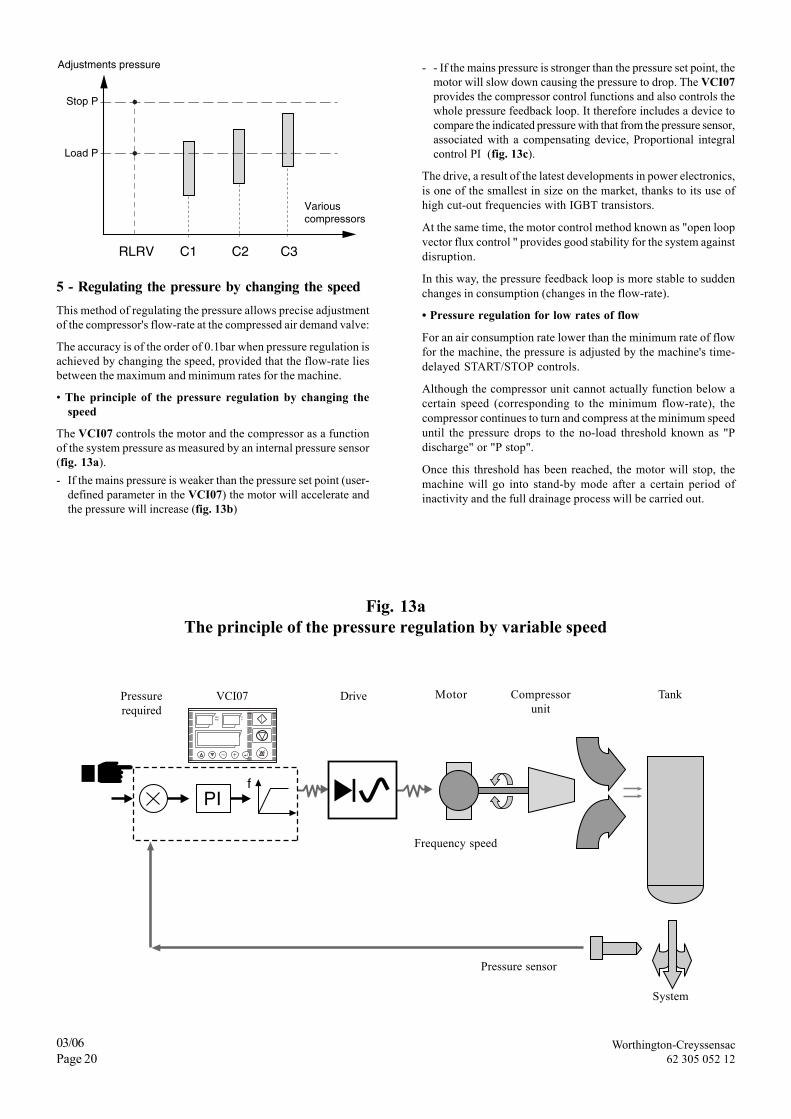
RLRV C1 C2 C3
Variouscompressors
Adjustments pressure
Stop P
Load P
5 - Regulating the pressure by changing the speedThis method of regulating the pressure allows precise adjustmentof the compressor's flow-rate at the compressed air demand valve:
The accuracy is of the order of 0.1bar when pressure regulation isachieved by changing the speed, provided that the flow-rate liesbetween the maximum and minimum rates for the machine.
• The principle of the pressure regulation by changing thespeed
The VCI07 controls the motor and the compressor as a functionof the system pressure as measured by an internal pressure sensor(fig. 13a).- If the mains pressure is weaker than the pressure set point (user-
defined parameter in the VCI07) the motor will accelerate andthe pressure will increase (fig. 13b)
- - If the mains pressure is stronger than the pressure set point, themotor will slow down causing the pressure to drop. The VCI07provides the compressor control functions and also controls thewhole pressure feedback loop. It therefore includes a device tocompare the indicated pressure with that from the pressure sensor,associated with a compensating device, Proportional integralcontrol PI (fig. 13c).
The drive, a result of the latest developments in power electronics,is one of the smallest in size on the market, thanks to its use ofhigh cut-out frequencies with IGBT transistors.
At the same time, the motor control method known as "open loopvector flux control " provides good stability for the system againstdisruption.
In this way, the pressure feedback loop is more stable to suddenchanges in consumption (changes in the flow-rate).
• Pressure regulation for low rates of flow
For an air consumption rate lower than the minimum rate of flowfor the machine, the pressure is adjusted by the machine's time-delayed START/STOP controls.
Although the compressor unit cannot actually function below acertain speed (corresponding to the minimum flow-rate), thecompressor continues to turn and compress at the minimum speeduntil the pressure drops to the no-load threshold known as "Pdischarge" or "P stop".
Once this threshold has been reached, the motor will stop, themachine will go into stand-by mode after a certain period ofinactivity and the full drainage process will be carried out.
Pressurerequired
VCI07 Drive Motor Compressorunit
Tank
System
Pressure sensor
Frequency speed
Fig. 13aThe principle of the pressure regulation by variable speed
Worthington-Creyssensac62 305 052 12
03/06Page 21
Fig. 5 b Fig. 5 c Fig. 5 d
Pressure
Speed
Flow Q
Time
Time
Time
Stopthreshold
Instructions
Min speed
Min Q
Requiredpressure
stop timing
minimun time
Fig. 13b Fig. 13c Fig. 13d
E - Operating incidents
The staff in charge of maintenance of the ROLLAIR® compressor must become fully acquainted with this machine, in order to be able to easilydiagnose any anomaly. Under normal operating conditions, the ROLLAIR® compressor must provide full satisfaction.
1 - Main incidents
The main incidents likely to occur are listed below, along with the remedies to be applied.(see Notice VCI07 62 205 930 xx).
Observed defects Possible causes Solutions
1. FAULT SIGNAL DISPLAYED a) Incident controller/machine. a) See notice VCI07.ON THE VCI07 CONTROLLER b) Incident motorisation. b) See notice for the variable speed drive unit
ALSO SEE Chapter 9.
The pressure then drops towards the indicated pressure and, atthe end of the minimum time delay (since reaching the no-loadpressure), the drive allows the motor to restart. The pressure thenrises again and the cycle starts over (fig. 13d).
To avoid pumping the system - frequent stop / start - drainagetime may be increased (see notice VCI07).
• Energy saving
For demand of compressed air within the machine's flow range -min flow to max flow, the frequency converter or the variable
speed drive feed the motor in order to ensure that it turns at thespeed required to supply air demand both for pressure and flow.
It is used to adjust the power supply to the motor (and thus themachine) to the exact power requirement for the compression ofthe air, without a drainage stage being necessary.
COMMENT:
Energy savings are increased if machine maintenance is carried outin accordance with the maintenance instructions and frequency.
Worthington-Creyssensac62 305 052 12
03/06Page 22
Chapter 7 - Integrated dryerThe ROLLAIR® 15-20-25-30-40 integrated dryer is a direct expansion refrigeration machine with a dry evaporator. The air to dry is conveyedto the exchanger in which the water vapor is condensed : the water from the condensation is collected in the separator and removed to theexterior.
A - Technical data
1 - Technical features
TYPE MAX. POWER COOLING NOMINAL NOMINAL TOTAL IntakeWEIGHT SUPPLY LIQUID LOAD POWER POWER POWER POWER
Room temperature: 25 °CAir intake temperature: 35 °CService pressure: 7 barsDew point under pressure: 3 °C
Service conditions:
Maximum room temperature: 45°CMinimum room temperature: 4°CMaximum air intake temperature: 55°CMaximum operational pressure: 13 bars
• Autotransformer option available to connect the dryer power supply directly to the machine.
Worthington-Creyssensac62 305 052 12
03/06Page 23
TYPE Air intake Air exhaust Water removalØ Ø from condensation Ø
IW21/IW27 1"1/2 Gas F. 1"1/2 Gas F. 1/4"
Exploded views (fig. 14)IW 21 - IW 27
Reference Description Reference Description
1 Cooling compressor 6 Coolant filter2 Condenser 7 Hot gas by-pass valve3 Fan 8 Pressure switch4 Evaporator 9 Condensate bleed solenoid valve5 Condensate separator 10 Condensate outlet pipe
Fig. 14
510
8
6
7
3
1
4
2
9
Worthington-Creyssensac62 305 052 12
03/06Page 24
AIR EXHAUST
AIR INTAKE
CONDENSATIONDRAINING
410
6
11
514 13
1
12
9
3
2
7
8
B - Operation
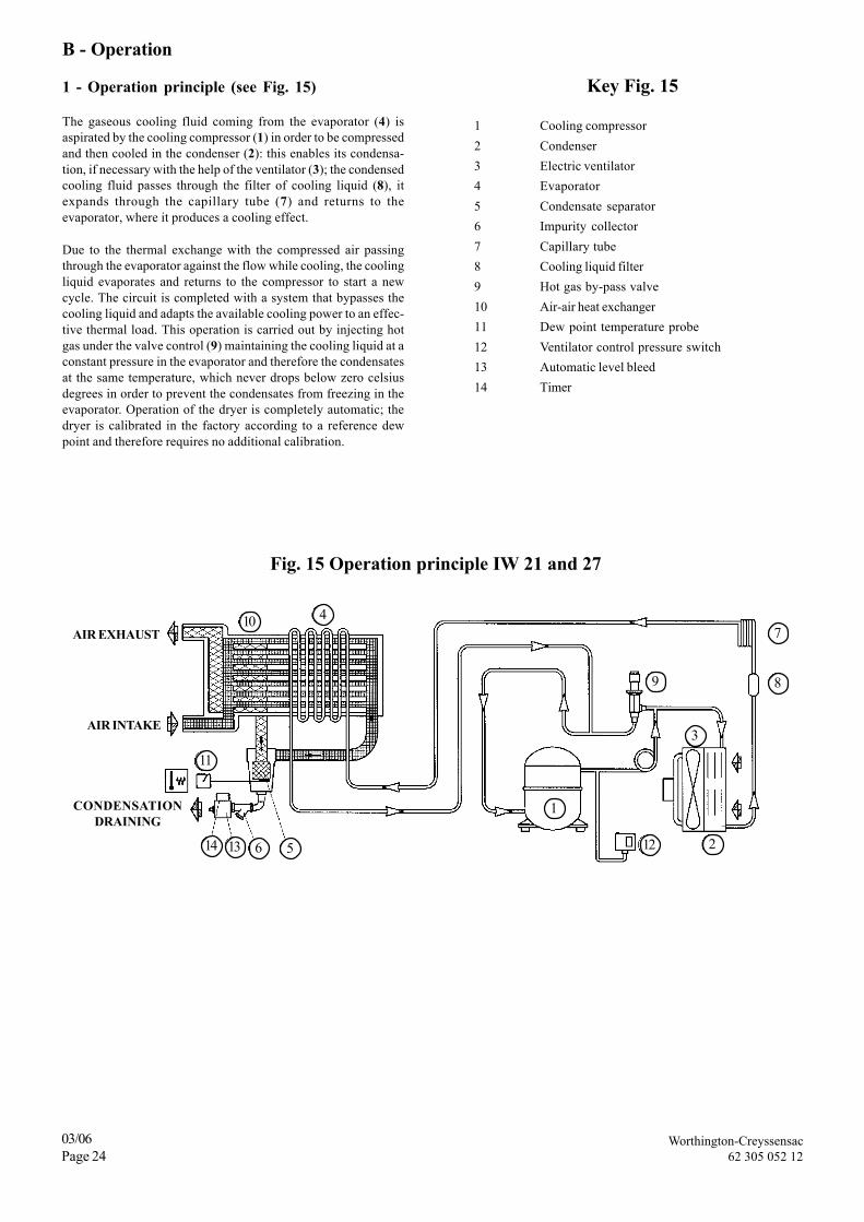
1 - Operation principle (see Fig. 15)
The gaseous cooling fluid coming from the evaporator (4) isaspirated by the cooling compressor (1) in order to be compressedand then cooled in the condenser (2): this enables its condensa-tion, if necessary with the help of the ventilator (3); the condensedcooling fluid passes through the filter of cooling liquid (8), itexpands through the capillary tube (7) and returns to theevaporator, where it produces a cooling effect.
Due to the thermal exchange with the compressed air passingthrough the evaporator against the flow while cooling, the coolingliquid evaporates and returns to the compressor to start a newcycle. The circuit is completed with a system that bypasses thecooling liquid and adapts the available cooling power to an effec-tive thermal load. This operation is carried out by injecting hotgas under the valve control (9) maintaining the cooling liquid at aconstant pressure in the evaporator and therefore the condensatesat the same temperature, which never drops below zero celsiusdegrees in order to prevent the condensates from freezing in theevaporator. Operation of the dryer is completely automatic; thedryer is calibrated in the factory according to a reference dewpoint and therefore requires no additional calibration.
Key Fig. 15
1 Cooling compressor2 Condenser3 Electric ventilator4 Evaporator5 Condensate separator6 Impurity collector7 Capillary tube8 Cooling liquid filter9 Hot gas by-pass valve10 Air-air heat exchanger11 Dew point temperature probe12 Ventilator control pressure switch13 Automatic level bleed14 Timer
Fig. 15 Operation principle IW 21 and 27
Worthington-Creyssensac62 305 052 12
03/06Page 25
C - Installation
1 - Inspection
Upon receiving the machine, make sure it is intact by checking forany parts that may be visibly damaged. In case of doubt, do notuse the machine and contact Worthington-Creyssensac's customerservice department.
2 - Electrical connections
ACCESS TO THE ELECTRIC CABINET IS RESTRICTEDTO PROFESSIONALLY QUALIFIED PERSONNEL ONLY.MAKE SURE ALL POWER SUPPLY TO THE UNIT ISDISCONNECTED BEFORE OPENING THE DOOR OF THEELECTRIC CABINET. IT IS ESSENTIAL THAT YOU RES-PECT THE REGULATIONS IN FORCE CONCERNINGELECTRICAL INSTALLATIONS FOR PERSONNELSAFETY AND TO PROTECT THE MACHINE.
• Check that the mains voltage corresponds to the voltage specifiedon the insert.
• Check the condition of the conductors and make sure that thereis efficient ground.
• Check, the upper part of the machine, for the automatic inter-ruption device for overloads with a differential circuit breakercalibrated at 30 mA.
Transformer option for the dryer's internal electrical supply :
• If the dryer autotransformer option is installed, the relatedelectrical power supply is through the general power supply ofthe compressor.
3 - Condensate bleed solenoid valve
The dryer is fitted with a condensate separator with an automaticrelease solenoid valve in order to get rid of the condensed waterafter cooling. Reconnect the drainpipes to the condensate collector(See page 18 item. 15 Fig. 14a).
D - Start up1 - Preparing for start-upAfter carrying out all the checks stipulated in Chapter 3, followthe instructions.
BEFORE ANY MAINTENANCE WORK IS CARRIED OUT,THE MACHINE AND THE DRYER MUST BE TURNEDOFF, AND THE UNIT'S ELECTRICAL POWER SUPPLY
MUST BE DISCONNECTED
2 - Stopping and startingWith Rollair 15-20-25-30-40, dryer start up is managed by thecompressor control board. Compressor starting may be deferredin relation to dryer starting so that the dryer can reach the necessarydew point. Like this, there is no condensation in the compressedair network. This adjustment is made on the MCI01 or PCI07control board (see paragraph D Chapter 1).
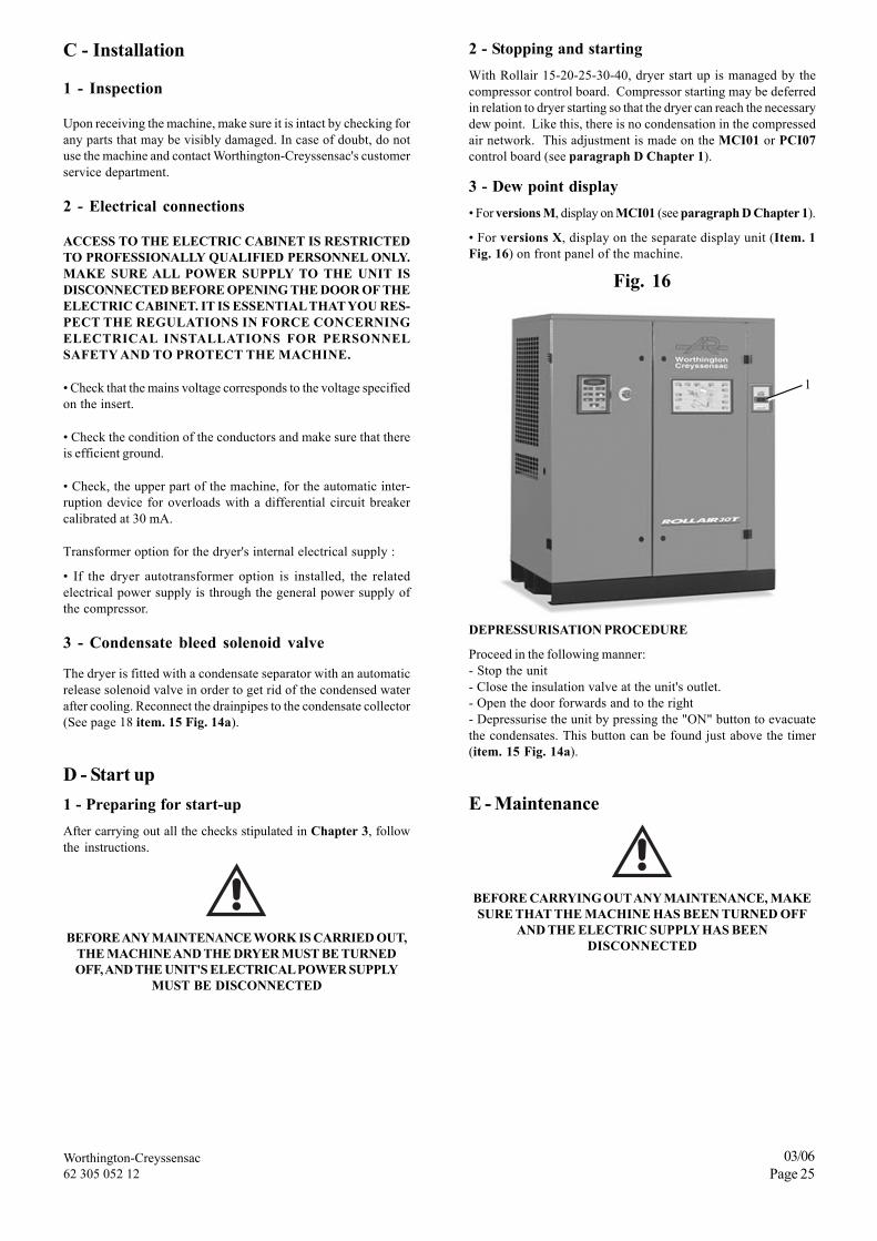
3 - Dew point display• For versions M, display on MCI01 (see paragraph D Chapter 1).
• For versions X, display on the separate display unit (Item. 1Fig. 16) on front panel of the machine.
Fig. 16
DEPRESSURISATION PROCEDURE
Proceed in the following manner:- Stop the unit- Close the insulation valve at the unit's outlet.- Open the door forwards and to the right- Depressurise the unit by pressing the "ON" button to evacuatethe condensates. This button can be found just above the timer(item. 15 Fig. 14a).
E - Maintenance
BEFORE CARRYING OUT ANY MAINTENANCE, MAKESURE THAT THE MACHINE HAS BEEN TURNED OFF
AND THE ELECTRIC SUPPLY HAS BEENDISCONNECTED
1
Worthington-Creyssensac62 305 052 12
03/06Page 26
3 - By-passing the dryer Fig. 17cDuring a dryer malfunction after the depressurisation process, itis possible to isolate the dryer by bypassing it as shown inFigure 18b (see diagram in the list of replacement parts). This setup allows the machine to be used without the dryer.
Fig. 18a (UPLINE from the By-pass)
Fig. 18b (DOWNLINE from the By-pass)
4 - Shutting off the machineIf the machine is to remain idle for a long time:- Stop the unit- Disconnect the electrical supply from the unit- Close the isolation gates- Depressurise the unit
During the period of inactivity, the machine must be protectedfrom atmospheric agents, dust and humidity, which could damagethe motors and the electrical system.To start it up again, consult Worthington-Creyssensac's after-sales service.
5 - Disposing of the unitIf the machine is dismantled, it must be separated into equal partsto be recycled or disposed of according to the standards that arecurrently in force.
WE STRONGLY RECOMMEND FOLLOWING THESTANDARDS THAT ARE CURRENTLY IN FORCE FORRECYCLING USED OILS AND OTHER POLLUTANTS
SUCH AS THE THERMAL INSULATION FOAMAND COOLANT GAS.
1 - Periodic maintenanceThese maintenance intervals are recommended for well-ventilatedplaces with no dust.For particularly dusty locations, double the maintenancefrequency.
Weekly Condensate Clean the filter of therelease valve condensate release valve
Clean the fins toMonthly Condenser eliminate any dust
accumulation
2 - Cleaning the condenser Fig. 17a and 17b
The condenser must be cleaned once a month.Proceed as follows:- Stop the unit.
- Cut off the mains supply
- Remove the rear panel (Fig. 17a).- Clean the condenser vanes (Fig. 17b) with a jet of air.
Fig 17a
Fig 17b
DO NOT USE WATER OR SOLVENTS
Worthington-Creyssensac62 305 052 12
03/06Page 27
F - Troubles hooting and emergency solutionsN.B : THE OPERATIONS SIGNALLED BY MUST BE CARRIED OUT BY PROFESSIONALLY QUALIFIED PERSONNEL WHOARE AUTHORISED BY WORTHINGTON-CREYSSENSAC.
Observed defects Possible causes Solutions
1. The air does not pass through to the The interior tubes are blocked by frost. Check that the hot gas by-pass valve isdryer's outlet. correctly adjusted and in good working
order.
2. There is condensed water in the circuit. a) The operation of the water separator. a) Check that the condensation separatorbleed valve works properly.
b) The dryer is operating in bad b) Check correct operation of the dryercondensation conditions. and its fan.
3. Continuous leak of air and water from Defective automatic condensation bleeding Check the system.the condensation separator. system.
4. The top of the dryer's compressor is a) See 2b.very hot (> 55°C). b) The refrigeration circuit does not Check all coolant gas leaks.
work with the correct amount of gas. Refill the coolant gas.
5. The motor works intermittently See 2b.because of the protection thermostat. See 4.
6. The dryer's motor groans but will a) Defective electrical connections. a) Check the condition and tightness ofnot start. the electrical connections.
b) You have stopped and restarted the b) Wait a few minutes before restartingdryer without waiting for the pressure the dryer.readjustment.c) The dryer motor starting system is c) Check the operation of the relay anddefective. the operation of the condensers and
engine start up (possible).
7. The dryer has stopped and will not a) Fuses a) Check the fuses.restart, even after a few minutes. b) The thermostatic protection with manual b) Reload or wait for the head of the
starting has begun to operate. compressor to cool down.See case 2b and 4.c) The high-pressure switch has begun c) Reload the pressure switch.operation. d) Check the integrity of the electricald) The motor is out of order. connection and its insulation.
8. The dryer's compressor makes too Problems with the internal mechanicalmuch noise. organs or with the compressor valves.
9. The condensation separator does not Automatic condensation bleeding Bleed the unit by opening the manualwork. system is cleaned. bleed valve. Have the system checked.
10.Dew point under too much pressure. a) Room temperature is too high. a) Check and correct the cooling airinlet if required.
b) Lack of coolant. b) Make sure the circuit is watertight,have it recharged.
c) Cooling compressor does not work. c) Check the dryer electricity supply.d) Evaporator pressure is too high. d) See 11.e) Condenser pressure is too high. e) See 12.
11.Evaporator pressure is too high. a) Maladjustment or breakdown of the a) Have the by-pass valve readjusted.by-pass valve of the hot coolant gas.b) Condenser pressure either too high or b) See 12.too low.c) Lack of coolant. c) Make sure the circuit is watertight,
have it recharged.
12.Condenser pressure is too high. a) Defective fan pressure switch. a) Carry out a replacement of the part.b) Defective fan. b) Check the fan.c) Room temperature is too high. c) Check and correct the cooling air
inlet if required.d) Condenser is clogged on the outside. d) Clean the condenser fins.
Worthington-Creyssensac62 305 052 12
03/06Page 28
Operations to be carried out Daily 500 h Every Every Every Every
150 h 2 000 h (*) 4 000 h 6 000 hDrain the condensates
Draining cock X from the cold oil circuit(Chapter 8 - G)
Oil level X Check and top up ifnecessary (Chap. 8 - A)
Air filter X Replace the filterOil change, oil refill
Oil tank, oil change X X with recommended oil(Chapter 8 - A)Control, cleaning,
Suction housing X greasing.Schedule replacementof the box every12000 hours. Use thesuction box kit.Check the cleanliness of
Oil return pipe X the oil return pipe andthe state of the seal(Chapter 8 - F)Exchange the cartridge
De-oiling cartridge X following the instructionsgiven in the specifications.(Chapter 8 - E)
Oil filter X X Change the filter.Oil radiator Blow cooling elements.Final air cooler X Clean.
Valve at minimum Exchange the accessoriesX supplied with the
maintenance kitElectric cabinet X X Retighten power cable
connections.Safety temperature Check operationthermometer test (Chapter 8 - I)(version M) X
NOTE : maintenance kits are available (see spare parts list). (*) or at least every year
Parts Observations
Section 8 - MaintenanceThe periodic maintenance is limited to a few essential operations. Itis expressly recommended to disconnect the power supply whencarrying out inspection or repair work on the machine.
The mimic diagram on the control panel shows, at a glance, thetype of operations to be carried out and their frequency, to ensurethe adequate operation of the compressor.
A - Oil change and oil level (see B Chapter 1)The oil recommended and used in the factory for the initial fill-upof the compressor is a mineral oil with the following specificproperties:• viscosity : 40 cSt à 40 °C (ISO 46),• viscosity index : 90 minimum,• antioxidizing additives,• anticorrosive additives,• antimoss additives.
This ROTAIR 2000 oil has been specifically studied byWorthington-Creyssensac and it guarantees the user an oil changeinterval of 2000 hours, with a replacement of the de-oiling cartridgeafter 4000 hours.
THE FIRST OIL CHANGE MUST BE CARRIED OUT AFTERTHE FIRST 500 HOURS OF OPERATION.
Using a synthetic oil for compressors is also acceptable and meansless frequent oil changes: please speak to us about the compatibilityand oil change methodes.
The oil filter must be drained and replaced when indicated on theelectronic controller and when the corresponding countdown timerreaches 0 (see electronic board manual, Chapter1 D).
Worthington-Creyssensac62 305 052 12
03/06Page 29
Drain the heat compressor. In order to do this, stop it and makesure you disconnect the electric supply. Depressurize the tank byloosening the filling plug by one turn. Open the bleeding valve anddrain it. Do not forget to close the valve after it has been drained.
After maintenance, you must reinitialise the counter which willtell you the number of hours remaining before the next oil changesee the specific notice on the electronic plate.
OIL LEVEL (fig. 19)
When stopped, the MAX level of oil is ¾ of the way up from thebottom of the indicator; the MINI level is at the lowest visiblepart of the indicator.
Fig. 19 - Oil level
THE OIL LEVEL HAS TO BE CHECKED AFTER HOT SHUT-DOWN OF THE COMPRESSOR (THERMOSTATIC VALVEOPEN).
Pressurized drainage (X version only)For fast and thorough draining, your ROLLAIR® is equippedwith a system for maintaining a slight pressure on the oil circuitwhen shutdown. This pressure is shown on the pressure gaugeplaced on the tank.
Follow the following procedure:• With the compressor hot, pressurized or, a soon as it begins no-load operation, stop the ROLLAIR® using STOP key (7) if the oilpressure circuit is above 3 bars or key (4) if the pressure is below3 bars (if the ROLLAIR® is stopped by key (7), wait until thepressure in the oil circuit falls to 3 bars then operate key (4) inorder to stop vacuumizing),
• Drain the oil by opening the drainage valve very gradually,
• When no pressure remains in the oil tank, change the oil filtercartridge,
• Is soon as oil no longer flows through the drainage port, close thevalve and fill up with new oil,
• Reset the hour meter which warns of the time to run before thenext drainage operation and the next oil filter change (see Docu-ment PCI07),
• Ensure filler plug tightness when reinstalling and check that allthe ports have been properly closed,
• The machine can only be restarted after pressing on keyboardkey 5 (R),
• After startup, check that there is no oil leak.
NOTEIf the oil is in poor condition: i.e. it gives off an acrid smell or con-tains particles of varnish or other solids, the system will have tobe rinsed out: pour in around 50% of the normal clean oil con-tents, run the set for 3 hours and carefully drain. During rinsing,leave the former oil filter cartridge in place.
B - Air filter (see Fig. 20, see B Chapter 1)
The air filter is of the dry, encapsulated type. Change the cartridgeevery 2,000 hours. Check the cleanliness of the filter every weekand change it if necessary.
IMPORTANTIf you do not replace the filtering element when needed, per-manent dirt build-up will result. This reduces the air inflow to thecompressor and could damage the oil separator and the compressor.
Fig. 20 - Air filter
C - TurbineReplacement of the complete fan is recommended if one or moreblades are deformed or broken If replaced, check the fan rotationdirection reversal of the rotation direction will reduce machinecooling and damage the motor in time.
D - Oil and air cooler
The aluminium oil and air cooler is a vital part in the ROLLAIR®
system. Please take care of this element. To prevent the nest oftubes from being deformed or damaged, when assembling ordisassembling the radiator unions and hoses, the radiator sleeves'must be kept rotating by means of a wrench. The outer surface ofthe nest of tubes must always be kept clean in order to enableproper heat transfer. In the event of a leak, the source of the leakmust be detected. In order to do this:
- Stop the ROLLAIR®.- Clean the greasy areas.- Look for leaks using conventional means (soap solution, …).
Filler plug
Oil level Drainage
Worthington-Creyssensac62 305 052 12
03/06Page 30
NOTERemove 3 screws (item. 1 - Fig. 21) then the plate of the collector(item. 2) to facilitate access to the cooler.
Fig. 21
Version X: shutdown under pressure helps keep pressure in themachine circuit for a short time meaning that a leak may be moreeasily detected.
E - De-oiling cartridge (Fig. 22)(see B Chapter 1)
The useful life of the de-oiling cartridge will depend on how cleanthe intake air to the compressor is, regular oil filter cartridge chan-ges, the quality of the oil used, the care taken when bleeding thecondensation from the oil tank and on the room temperature.The de-oiling cartridge (item. 1 Fig. 22) should be replaced whenthe warning light 2 "FLT" flashes and when the relevant hourlycountdown counter reaches 0.After replacing the de-oiling cartridge, restart the clock, which willlet you know how much time is left before it needs to be changedagain. See the specific MCI01 instructions.
Excessive oil consumptionExcessive oil in the discharged air and a sudden drop in the levelare signs that the de-oiling cartridge has probably deteriorated andmust be changed. In the first place, the compressor must be checkedto make sure that there are no oil leaks and that the oil returnmechanism is working properly.
Fig. 22
1. De-oiling cartridge
F - Oil return pipe (see Fig. 23)Placed under the compressor
• Dismantle the body of the anti-oil return pipe.• Lift the anti-oil return pipe.• Check the state of the o-ring (item. 1 Fig. 23).• Reassemble.
G - Draining condensation water(see B Chapter 1)
Condensation water prevents proper lubrication. The resultingsubstantial wear leads to a reduction in the lifespan of the ROLLAIR®.It is therefore essential to drain condensation water.
Draining of condensates in the oil circuit:
Draining will only take place at least 12 hours after the ROLLAIR®
has been shut down. It can be carried out for example on themorning of the start-up.
Fig. 23 - Oil return pipe
To do this :
- Slowly open the oil change tap and let the water escape.- When the oil appears, close the valve immediately to avoid any loss.- Refill with oil if necessary.
H - Temperature safety tests(See instructions electronic board).
IF THE SENSOR IS NOT WORKING, IT MUST BECHANGED.
I - Refastening electric connectionsA loosening of the electric power cables leads to the contactorsove-rheating which can lead to their destruction.
PERIODIC REFASTENING IS THEREFORE NECESSARY ATTHE STAR AND TRIANGLE LINE CONTACTOR ARRIVALSAND DEPARTURES. (SEE MAINTENANCE TABLE).
All electric power supply to the machine must be cut off beforeopening the electric cabinet.
J - Decommissioning the compressor atthe end of its useful life
1. Stop the compressor and close the air outlet valve.2. Unplug the compressor from the electric supply.3. Decompress the compressor : unplug the 4/6 piping on the
oil separator cover.4. Close and decompress the section of the air network which
is linked to the exit valve. Disconnect from the compressedair exit pipe from the air network.
5. Empty the circuits of oil and condensates.6. Disconnect the compressor condensate piping from the
condensate draining system.
1
1
2
1
Worthington-Creyssensac62 305 052 12
03/06Page 31
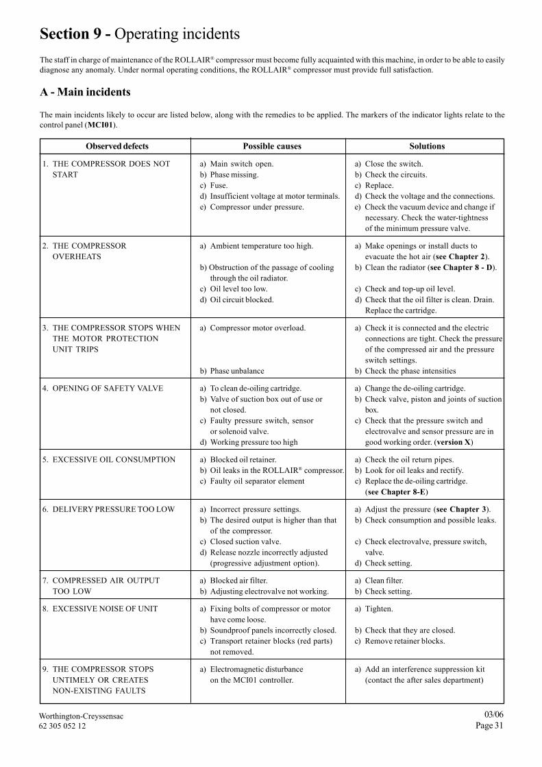
Section 9 - Operating incidentsThe staff in charge of maintenance of the ROLLAIR® compressor must become fully acquainted with this machine, in order to be able to easilydiagnose any anomaly. Under normal operating conditions, the ROLLAIR® compressor must provide full satisfaction.
A - Main incidents
The main incidents likely to occur are listed below, along with the remedies to be applied. The markers of the indicator lights relate to thecontrol panel (MCI01).
Observed defects Possible causes Solutions
1. THE COMPRESSOR DOES NOT a) Main switch open. a) Close the switch.START b) Phase missing. b) Check the circuits.
c) Fuse. c) Replace.d) Insufficient voltage at motor terminals. d) Check the voltage and the connections.e) Compressor under pressure. e) Check the vacuum device and change if
necessary. Check the water-tightnessof the minimum pressure valve.
2. THE COMPRESSOR a) Ambient temperature too high. a) Make openings or install ducts toOVERHEATS evacuate the hot air (see Chapter 2).
b) Obstruction of the passage of cooling b) Clean the radiator (see Chapter 8 - D).through the oil radiator.
c) Oil level too low. c) Check and top-up oil level.d) Oil circuit blocked. d) Check that the oil filter is clean. Drain.
Replace the cartridge.
3. THE COMPRESSOR STOPS WHEN a) Compressor motor overload. a) Check it is connected and the electricTHE MOTOR PROTECTION connections are tight. Check the pressureUNIT TRIPS of the compressed air and the pressure
switch settings.b) Phase unbalance b) Check the phase intensities
4. OPENING OF SAFETY VALVE a) To clean de-oiling cartridge. a) Change the de-oiling cartridge.b) Valve of suction box out of use or b) Check valve, piston and joints of suction
not closed. box.c) Faulty pressure switch, sensor c) Check that the pressure switch and
or solenoid valve. electrovalve and sensor pressure are ind) Working pressure too high good working order. (version X)
5. EXCESSIVE OIL CONSUMPTION a) Blocked oil retainer. a) Check the oil return pipes.b) Oil leaks in the ROLLAIR® compressor. b) Look for oil leaks and rectify.c) Faulty oil separator element c) Replace the de-oiling cartridge.
(see Chapter 8-E)
6. DELIVERY PRESSURE TOO LOW a) Incorrect pressure settings. a) Adjust the pressure (see Chapter 3).b) The desired output is higher than that b) Check consumption and possible leaks.
of the compressor.c) Closed suction valve. c) Check electrovalve, pressure switch,d) Release nozzle incorrectly adjusted valve.
7. COMPRESSED AIR OUTPUT a) Blocked air filter. a) Clean filter.TOO LOW b) Adjusting electrovalve not working. b) Check setting.
8. EXCESSIVE NOISE OF UNIT a) Fixing bolts of compressor or motor a) Tighten.have come loose.
b) Soundproof panels incorrectly closed. b) Check that they are closed.c) Transport retainer blocks (red parts) c) Remove retainer blocks.
not removed.
9. THE COMPRESSOR STOPS a) Electromagnetic disturbance a) Add an interference suppression kitUNTIMELY OR CREATES on the MCI01 controller. (contact the after sales department)NON-EXISTING FAULTS
Worthington-Creyssensac62 305 052 12
03/06Page 32
Worthington – CreyssensacZone industrielle - BP 80419 - 4, rue Émile Zola - 60114 Méru Cedex
http://www.airwco.com
CAUTIONWhen the compressed air cools, part of the moisture sucked in by the compressor condenses. In order to protectthe dryer against the risk of an ice plug forming, it is essential to check regularly that the condensate drains areoperating properly :
On the compressed air storage reservoir and on the filters :• With a manual drain, drain regularly according to the moisture content of the ambient air.• With an automatic drain, set the draining cycle accordingly and check that the drain is in good working condition.
This recommendation is also fundamental in a circuit comprising an adsorption dryer (risk of saturation of thealumina).