70
Compu-M Technology based. Customer driven. December 1996 Instruction Manual PL-516 33455160 Rev 1.0
Compu-M
Technology based. Customer driven.
December 1996
Instruction Manual
PL-516
33455160Rev 1.0

Thank you for purchasing Milltronics’ products. We endeavour to design equipment that is
simple to use and reliable in its operation, with the aim of satisfying our customers’ needs.
Milltronics has been designing and manufacturing process equipment since 1954. Our
fields of expertise include ultrasonic level measurement, in-line weighing of dry bulk solids
and motion sensing.
Milltronics is established world wide through associate offices and representatives. Our network
is continually being refined to provide our customers with first rate sales information, engineering
assistance and after sales support.
For more details on our products and service, please contact us and we will provide you with a
listing of the offices or representatives nearest you.
Canada : 1954 Technology Dr., P.O. Box 4225, Peterborough, Ontario, Canada K9J 7B1Tel.: 705-745-2431 Fax: 705-741-0466
U.S.A. : 709 Stadium Drive, Arlington, Texas U.S.A. 76011Tel.: 817-277-3543 Fax: 817-277-3894
England : Oak House, Bromyard Road, Worcester, England WR2 5XZ Tel.: 01905-748404 Fax: 01905-748430
France : Parc de la Sainte Victoire, Bât. 5, 13590 Meyreuil, FranceTel.: +33 4 42 65 69 00 Fax: +33 4 42 58 63 95
Belgium : August van de Wielelei 97, 2100 Deurne, Antwerp, BelgiumTel.: 03/326 45 54 Fax: 03/326 05 25
Mexico : Amores No. 1155, Col. Del Valle, 03100 Mexico D.F., MexicoTel.: 575-31-44 / 575-83-13 / 575-27-78 Fax: 575-26-86
Internet : http://www.milltronics.com
TABLE OF CONTENTS
Section Page
GENERAL INFORMATION
The Compu-M 5
About the Compu-M 5
SPECIFICATIONS
Compu-M 7
Current Output Isolator 8
Cabling 9
Options 9
INSTALLATION
Compu-M 11
Outline and Mounting 12
Compu-M Layout 13
Interconnection 14
System Diagram 14
Compu-M / Belt Scale 15
Compu-M / MMI-2 16
Compu-M / Speed Sensor 17
Compu-M / Flowmeter 18
Ancillary Connections 19
Power Connections 22
PROGRAMMING
Operating Modes 23
Keypad 23
Parameter Entry 24
Display Messages 25
PL-516 3
APPLICATIONS
Belt Scales
Operation 27
Initial Start Up 28
Programming Chart - Example 35
Recalibration 36
Solids Flowmeters
Operation 41
Test Rate 42
Initial Start Up 42
Programming Chart - Example 48
Recalibration 49
PARAMETERS 53
PROGRAMMING CHART 69
PL-516 4
GENERAL INFORMATION
ABOUT THIS MANUAL
It is essential that this instruction manual, PL-453, be referred to during the installation and start up of the Compu-M.
Applications, provides operation, and programming/calibration information specific to Compu-M applications.The programming/calibration of the Compu-M may be further optimized by referring to Parameters.
To assist the operator in programming the Compu-M, a Programming Chart is provided. Transfer the required data from the Design Data Sheet or the values established from Parameters onto the ProgrammingChart. The Programming Chart parameter orientation is designed to permit convenient sequential parameterprogramming. The programming chart may be folded out so the chart and Parameters may be reviewed simultaneously.
ABOUT THE COMPU-M
The Compu-M is to be used only in the manneroutlined in this instruction manual.
The Compu-M is a microprocessor based integrator designed specifically for bulk dry solids in-line weighing applications.
If the current material transport system is by conveyor belt, the Compu-M is used in conjunction with a beltscale. The Compu-M provides a local display of: load, speed, flowrate and total flow.
If the application material is free flowing, the Compu-M is combined with a dry solids flowmeter. TheCompu-M provides flowrate and total flow displays.
The Compu-M also provides an analog mA output signal proportional to flowrate, a contact for remote totalizeroperation and a relay contact for rate alarm.
Programming is accomplished via the front cover membrane keypad. The Compu-M prompts the operator toenter the information required to complete basic programming. Additional programming features may beutilized to tailor the Compu-M operation to a specific application.
The level of operator access may be defined to ensure programming is not inadvertently altered during normal operation.
Calibration is automatic and relatively simple to achieve. In the calibrate mode, operating conditions aresimulated to perform a zero and span calibration. A material test may then be performed to verify systemaccuracy. If required, the Compu-M may be programmed to correct any accuracy deviation.
During normal operation the user may select any of the available local displays and select the display light ifdesired. Access to the totalizer reset feature and other functions may be permitted depending on the level ofoperator access chosen when the system was programmed.
PL-516 5

PL-516 6
SPECIFICATIONS
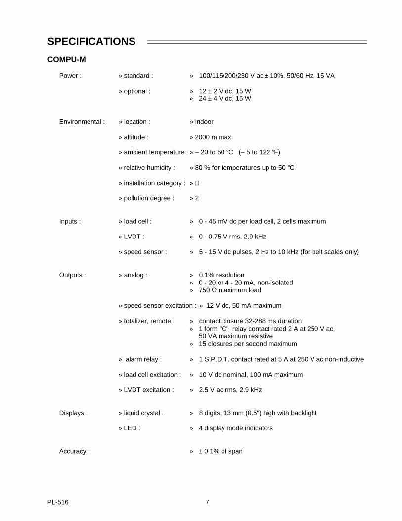
COMPU-M
Power : » standard : » 100/115/200/230 V ac ± 10%, 50/60 Hz, 15 VA
» optional : » 12 ± 2 V dc, 15 W» 24 ± 4 V dc, 15 W
Environmental : » location : » indoor
» altitude : » 2000 m max
» ambient temperature : » – 20 to 50 °C (– 5 to 122 °F)
» relative humidity : » 80 % for temperatures up to 50 °C
» installation category : » II
» pollution degree : » 2
Inputs : » load cell : » 0 - 45 mV dc per load cell, 2 cells maximum
» LVDT : » 0 - 0.75 V rms, 2.9 kHz
» speed sensor : » 5 - 15 V dc pulses, 2 Hz to 10 kHz (for belt scales only)
Outputs : » analog : » 0.1% resolution » 0 - 20 or 4 - 20 mA, non-isolated » 750 Ω maximum load
» speed sensor excitation : » 12 V dc, 50 mA maximum
» totalizer, remote : » contact closure 32-288 ms duration» 1 form "C" relay contact rated 2 A at 250 V ac,
50 VA maximum resistive» 15 closures per second maximum
» alarm relay : » 1 S.P.D.T. contact rated at 5 A at 250 V ac non-inductive
» load cell excitation : » 10 V dc nominal, 100 mA maximum
» LVDT excitation : » 2.5 V ac rms, 2.9 kHz
Displays : » liquid crystal : » 8 digits, 13 mm (0.5") high with backlight
» LED : » 4 display mode indicators
Accuracy : » ± 0.1% of span
PL-516 7
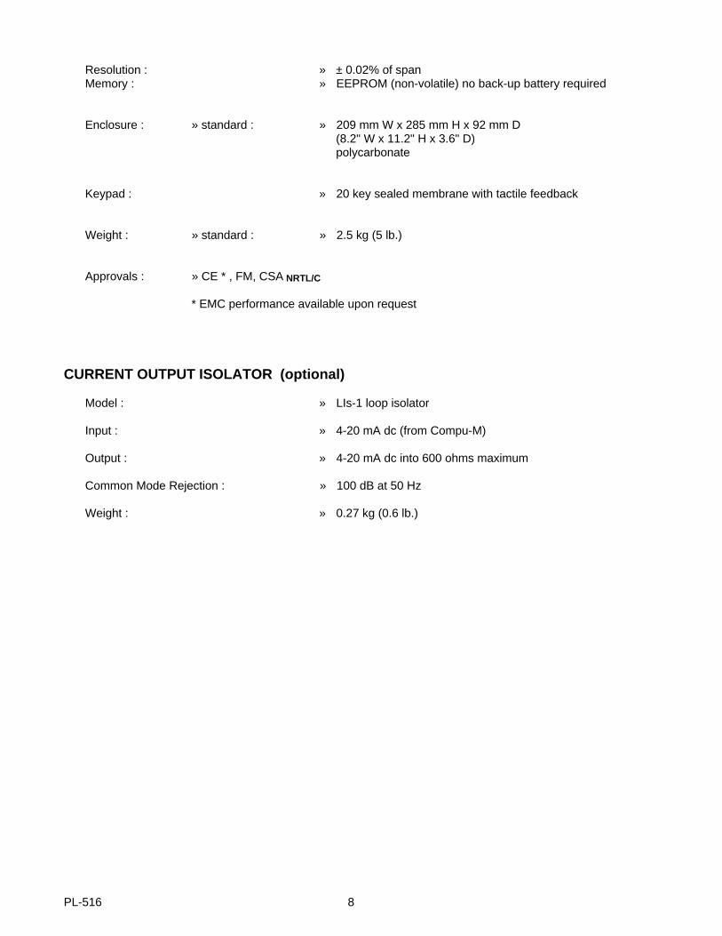
Resolution : » ± 0.02% of spanMemory : » EEPROM (non-volatile) no back-up battery required
Enclosure : » standard : » 209 mm W x 285 mm H x 92 mm D(8.2" W x 11.2" H x 3.6" D) polycarbonate
Keypad : » 20 key sealed membrane with tactile feedback
Weight : » standard : » 2.5 kg (5 lb.)
Approvals : » CE * , FM, CSA NRTL/C
* EMC performance available upon request
CURRENT OUTPUT ISOLATOR (optional)
Model : » LIs-1 loop isolator
Input : » 4-20 mA dc (from Compu-M)
Output : » 4-20 mA dc into 600 ohms maximum
Common Mode Rejection : » 100 dB at 50 Hz
Weight : » 0.27 kg (0.6 lb.)
PL-516 8
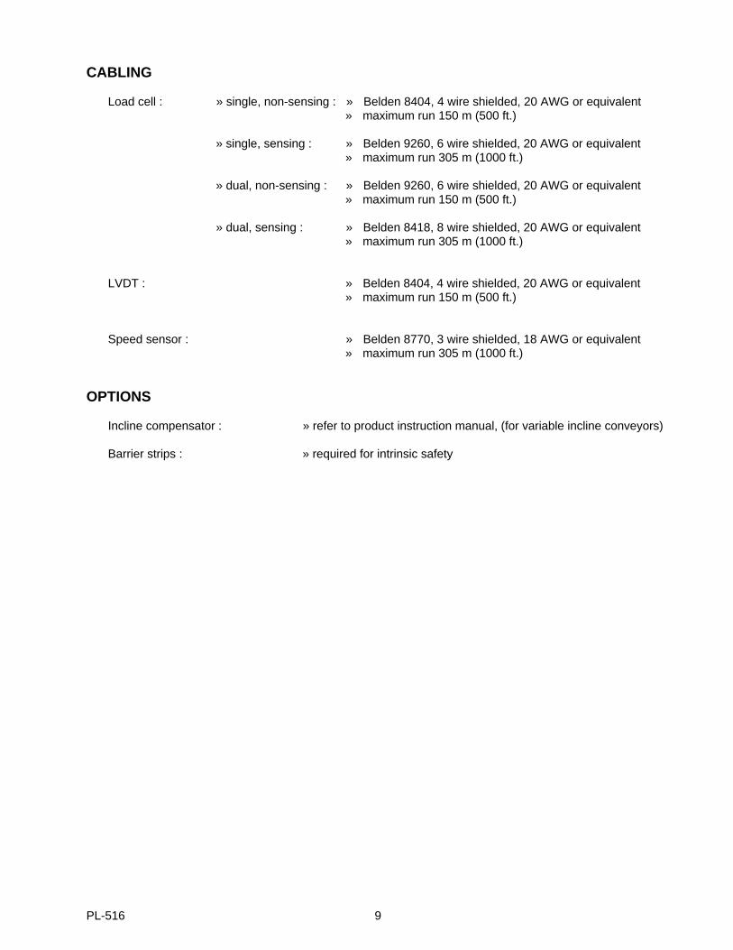
CABLING
Load cell : » single, non-sensing : » Belden 8404, 4 wire shielded, 20 AWG or equivalent » maximum run 150 m (500 ft.)
» single, sensing : » Belden 9260, 6 wire shielded, 20 AWG or equivalent » maximum run 305 m (1000 ft.)
» dual, non-sensing : » Belden 9260, 6 wire shielded, 20 AWG or equivalent » maximum run 150 m (500 ft.)
» dual, sensing : » Belden 8418, 8 wire shielded, 20 AWG or equivalent » maximum run 305 m (1000 ft.)
LVDT : » Belden 8404, 4 wire shielded, 20 AWG or equivalent» maximum run 150 m (500 ft.)
Speed sensor : » Belden 8770, 3 wire shielded, 18 AWG or equivalent » maximum run 305 m (1000 ft.)
OPTIONS
Incline compensator : » refer to product instruction manual, (for variable incline conveyors)
Barrier strips : » required for intrinsic safety
PL-516 9

PL-516 10
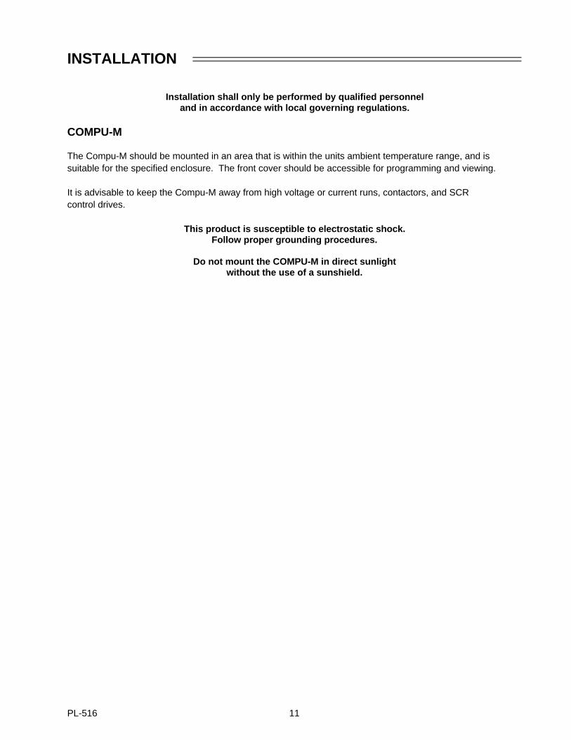
INSTALLATION
Installation shall only be performed by qualified personneland in accordance with local governing regulations.
COMPU-M
The Compu-M should be mounted in an area that is within the units ambient temperature range, and issuitable for the specified enclosure. The front cover should be accessible for programming and viewing.
It is advisable to keep the Compu-M away from high voltage or current runs, contactors, and SCR control drives.
This product is susceptible to electrostatic shock.Follow proper grounding procedures.
Do not mount the COMPU-M in direct sunlightwithout the use of a sunshield.
PL-516 11
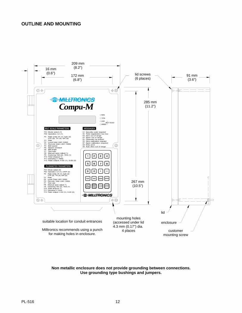
OUTLINE AND MOUNTING
suitable location for conduit entrances
Milltronics recommends using a punchfor making holes in enclosure.
91 mm(3.6")
lid screws(6 places)
209 mm(8.2")
172 mm(6.8")
16 mm(0.6")
285 mm(11.2")
267 mm(10.5")
lid
enclosure
customermounting screw
mounting holes(accessed under lid4.3 mm (0.17") dia.
4 places
Non metallic enclosure does not provide grounding between connections.Use grounding type bushings and jumpers.
PL-516 12
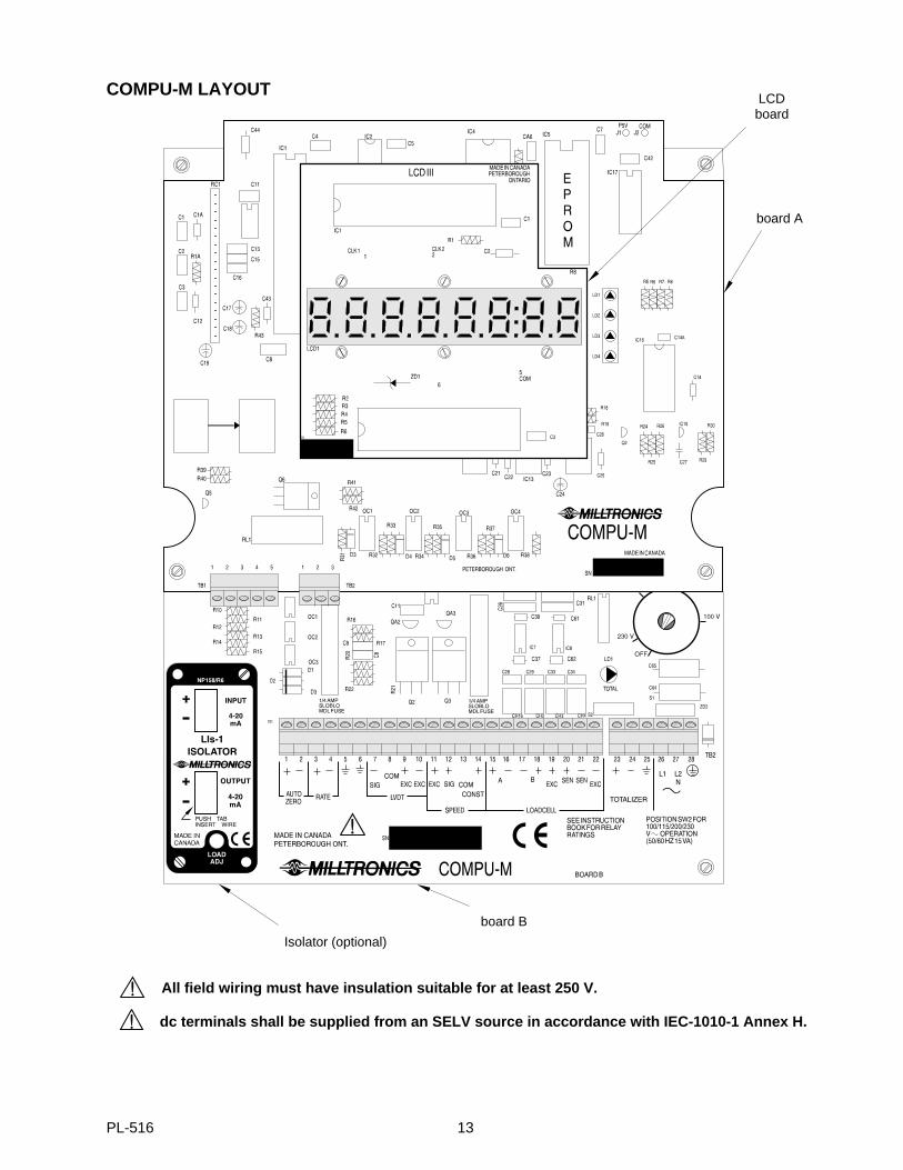
COMPU-M LAYOUT
board B
Isolator (optional)
LCDboard
board A
dc terminals shall be supplied from an SELV source in accordance with IEC-1010-1 Annex H.
All field wiring must have insulation suitable for at least 250 V.
PL-516 13
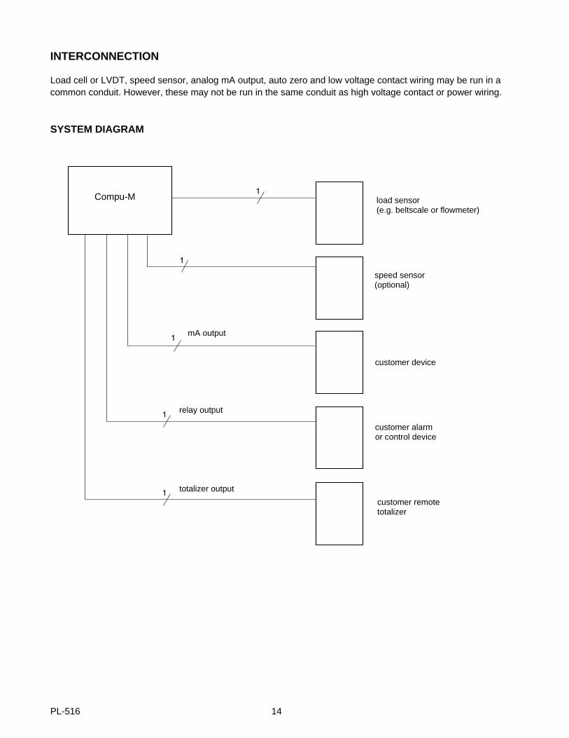
INTERCONNECTION
Load cell or LVDT, speed sensor, analog mA output, auto zero and low voltage contact wiring may be run in acommon conduit. However, these may not be run in the same conduit as high voltage contact or power wiring.
SYSTEM DIAGRAM
Compu-M load sensor(e.g. beltscale or flowmeter)
speed sensor(optional)
customer device
customer alarmor control device
customer remotetotalizer
relay output
totalizer output
mA output
PL-516 14
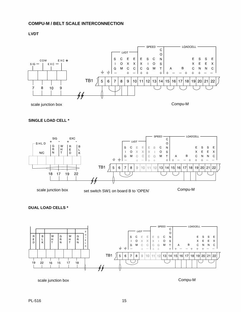
COMPU-M / BELT SCALE INTERCONNECTION
LVDT
SINGLE LOAD CELL *
DUAL LOAD CELLS *
Compu-Mscale junction box
set switch SW1 on board B to ‘OPEN’ Compu-Mscale junction box
Compu-Mscale junction box
PL-516 15
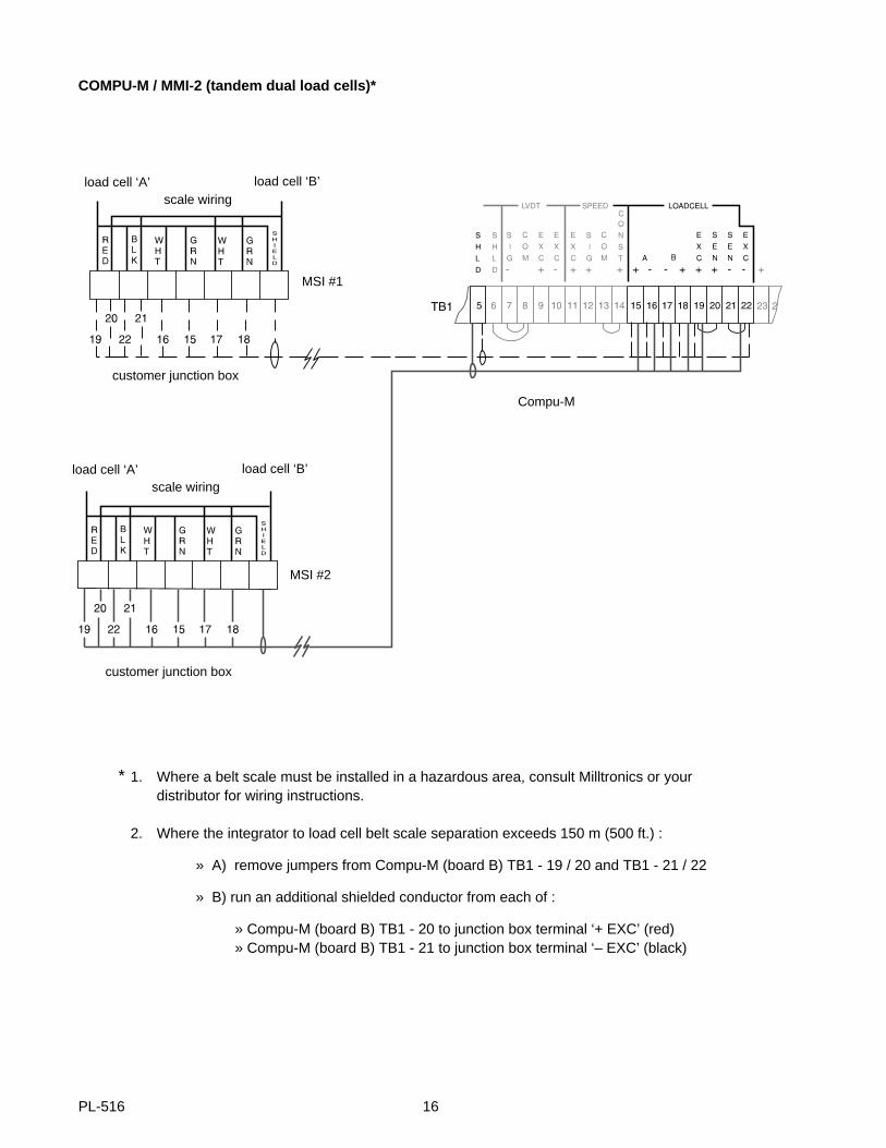
COMPU-M / MMI-2 (tandem dual load cells)*
* 1. Where a belt scale must be installed in a hazardous area, consult Milltronics or your distributor for wiring instructions.
2. Where the integrator to load cell belt scale separation exceeds 150 m (500 ft.) :
» A) remove jumpers from Compu-M (board B) TB1 - 19 / 20 and TB1 - 21 / 22
» B) run an additional shielded conductor from each of :
» Compu-M (board B) TB1 - 20 to junction box terminal ‘+ EXC’ (red)» Compu-M (board B) TB1 - 21 to junction box terminal ‘– EXC’ (black)
load cell ‘B’ load cell ‘A’
Compu-M
MSI #1
MSI #2
customer junction box
customer junction box
scale wiring
load cell ‘B’ load cell ‘A’ scale wiring
PL-516 16
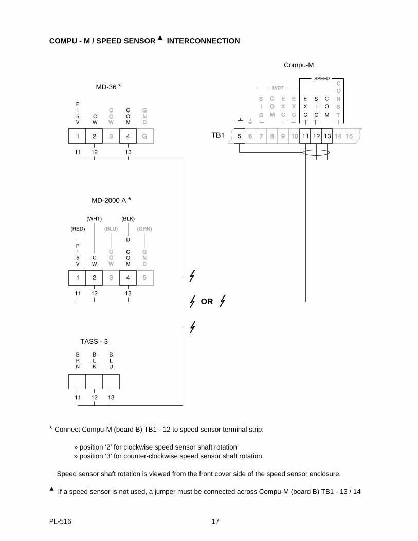
COMPU - M / SPEED SENSOR INTERCONNECTION
* Connect Compu-M (board B) TB1 - 12 to speed sensor terminal strip:
» position ‘2’ for clockwise speed sensor shaft rotation» position ‘3’ for counter-clockwise speed sensor shaft rotation.
Speed sensor shaft rotation is viewed from the front cover side of the speed sensor enclosure.
If a speed sensor is not used, a jumper must be connected across Compu-M (board B) TB1 - 13 / 14
MD-36 *
Compu-M
MD-2000 A *
TASS - 3
OR
PL-516 17
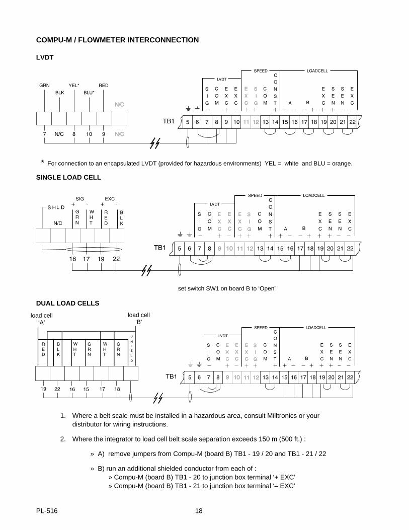
COMPU-M / FLOWMETER INTERCONNECTION
LVDT
SINGLE LOAD CELL
DUAL LOAD CELLS
1. Where a belt scale must be installed in a hazardous area, consult Milltronics or your distributor for wiring instructions.
2. Where the integrator to load cell belt scale separation exceeds 150 m (500 ft.) :
» A) remove jumpers from Compu-M (board B) TB1 - 19 / 20 and TB1 - 21 / 22
» B) run an additional shielded conductor from each of :» Compu-M (board B) TB1 - 20 to junction box terminal ‘+ EXC’ » Compu-M (board B) TB1 - 21 to junction box terminal ‘– EXC’
set switch SW1 on board B to ‘Open’
load cell‘A’
load cell‘B’
* For connection to an encapsulated LVDT (provided for hazardous environments) YEL = white and BLU = orange.
PL-516 18
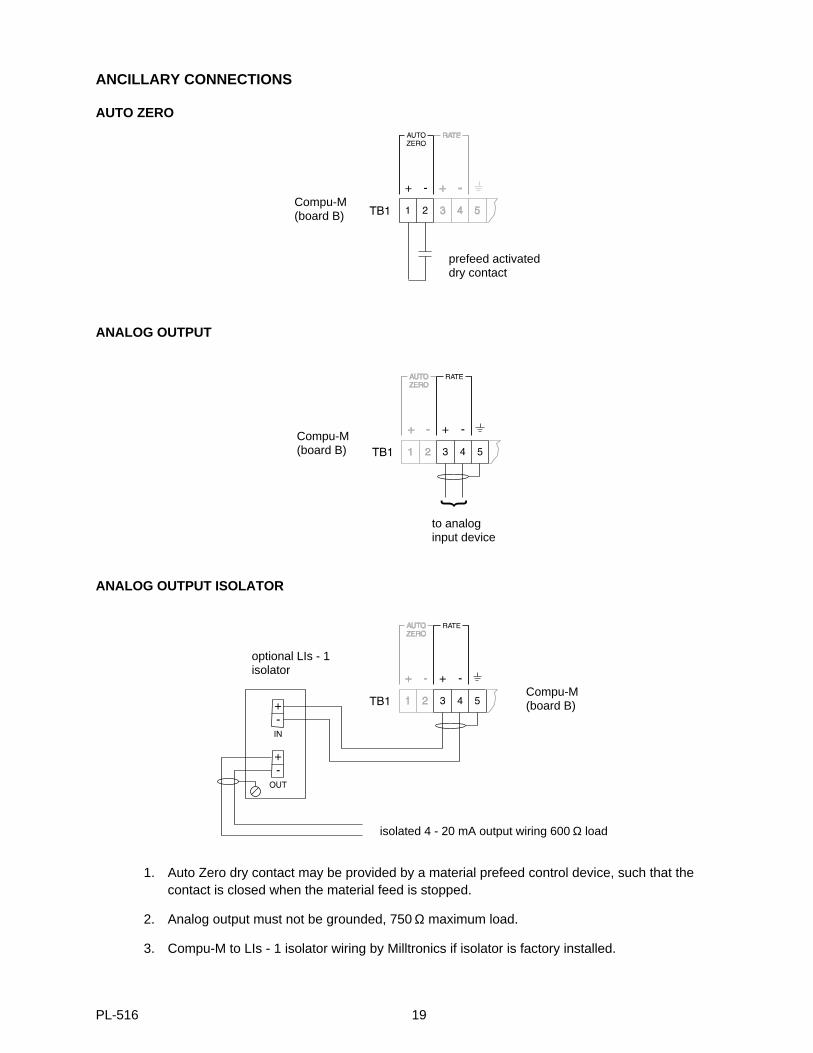
ANCILLARY CONNECTIONS
AUTO ZERO
ANALOG OUTPUT
ANALOG OUTPUT ISOLATOR
1. Auto Zero dry contact may be provided by a material prefeed control device, such that the contact is closed when the material feed is stopped.
2. Analog output must not be grounded, 750 Ω maximum load.
3. Compu-M to LIs - 1 isolator wiring by Milltronics if isolator is factory installed.
prefeed activateddry contact
to analoginput device
isolated 4 - 20 mA output wiring 600 Ω load
optional LIs - 1isolator
Compu-M(board B)
Compu-M(board B)
Compu-M(board B)
PL-516 19
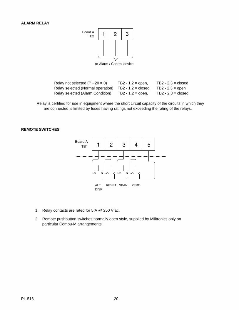
ALARM RELAY
REMOTE SWITCHES
1. Relay contacts are rated for 5 A @ 250 V ac.
2. Remote pushbutton switches normally open style, supplied by Milltronics only on particular Compu-M arrangements.
Relay not selected (P - 20 = 0) TB2 - 1,2 = open, TB2 - 2,3 = closedRelay selected (Normal operation) TB2 - 1,2 = closed, TB2 - 2,3 = openRelay selected (Alarm Condition) TB2 - 1,2 = open, TB2 - 2,3 = closed
Relay is certified for use in equipment where the short circuit capacity of the circuits in which they are connected is limited by fuses having ratings not exceeding the rating of the relays.
to Alarm / Control device
ALT RESET SPAN ZERODISP
PL-516 20
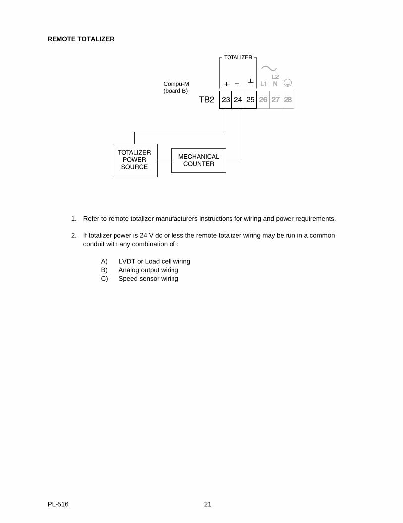
REMOTE TOTALIZER
1. Refer to remote totalizer manufacturers instructions for wiring and power requirements.
2. If totalizer power is 24 V dc or less the remote totalizer wiring may be run in a commonconduit with any combination of :
A) LVDT or Load cell wiringB) Analog output wiringC) Speed sensor wiring
Compu-M(board B)
PL-516 21
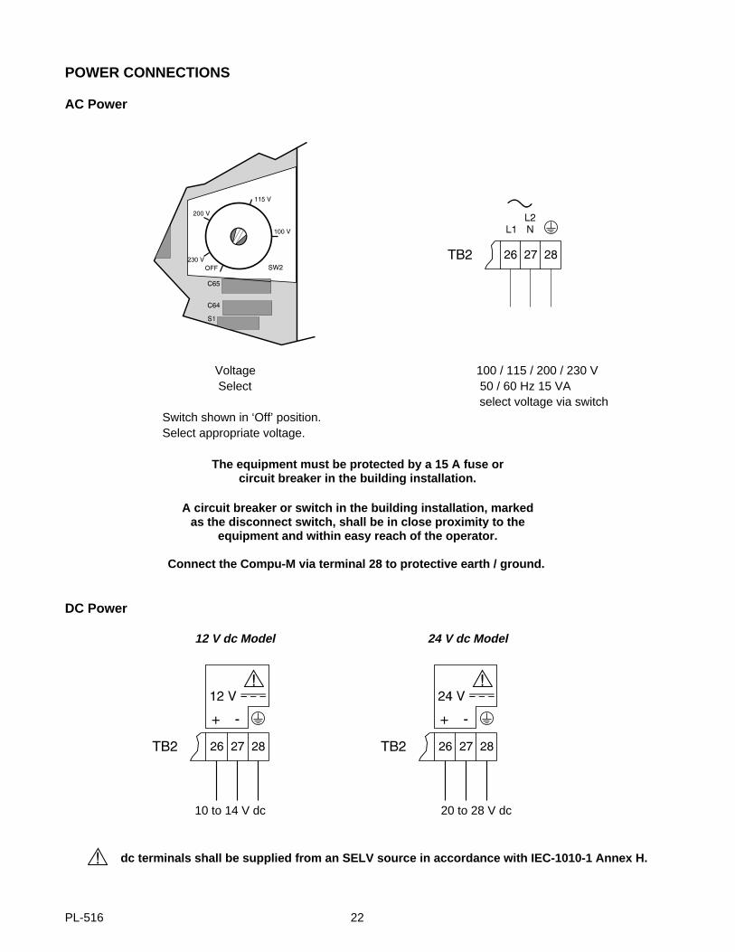
POWER CONNECTIONS
AC Power
Voltage 100 / 115 / 200 / 230 V Select 50 / 60 Hz 15 VA
select voltage via switchSwitch shown in ‘Off’ position.Select appropriate voltage.
The equipment must be protected by a 15 A fuse orcircuit breaker in the building installation.
A circuit breaker or switch in the building installation, markedas the disconnect switch, shall be in close proximity to the
equipment and within easy reach of the operator.
Connect the Compu-M via terminal 28 to protective earth / ground.
DC Power
12 V dc Model 24 V dc Model
10 to 14 V dc 20 to 28 V dc
dc terminals shall be supplied from an SELV source in accordance with IEC-1010-1 Annex H.
PL-516 22
PROGRAMMING
OPERATING MODES
The Compu-M has two selectable modes of operation: "Access" or "Run". In either mode, parameter valuesmay be viewed, accepted or altered, zero and span calibrations may be initiated and the totalizer may bereset. However the level of access to these functions is determined by the security parameter P66. Attemptingto perform a function outside of the access security level will result in a display message [ E1 ].
The access mode is automatically assumed upon initial power up and upon completion of zero and spancalibrations or Factoring (P9).
The run mode is the normal operating mode and may be selected by pressing "RUN" or "ALT DISP". In the runmode, the desired display mode is selected by pressing "ALT DISP" until the corresponding display modeindicator LED on the Compu-M front cover is illuminated.
All operator programmed information is maintained in non-volatile EEPROM memory and therefore is retainedin the event of a power interruption. The Compu-M will return to the previous operating mode when powerresumes.
The level of access security chosen may limit operator access to some of the following keypad functions.
KEYPAD
Button Function
"0"..."9" numeric entries
"4" increase analog mA output (P13 and P14 only)
"8" decrease analog mA output (P13 and P14 only)
"." decimal point
"-" access mode: negative entry,
run mode: activate/deactivate LCD backlight
"RUN" enter the run mode, return to previously selected display mode
"PAR" access parameter for entry or viewing
"ZERO" activate zero calibration or view current zero count
"SPAN" activate span calibration or view current span count
"ALT access mode: enter the run mode, return to previously selected display mode
DISP" run mode: scrolls through display modes, cancels Auto Scroll display (P21)
"RESET reset local totalizer to zero (0)TOTAL"
"CLEAR" clear display
"ENTER" enter parameter number selected, display current parameter value, enter display value into selected parameter number, acceptzero, or span calibration deviation
PL-516 23
PARAMETER ENTRY
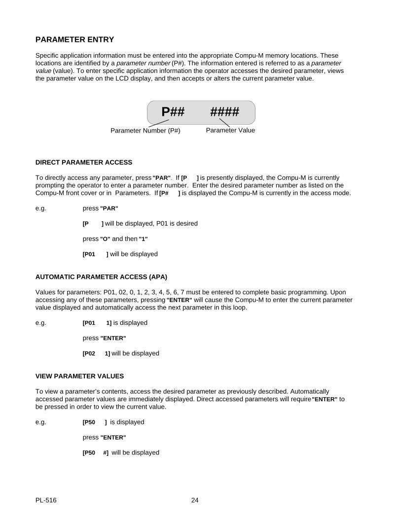
Specific application information must be entered into the appropriate Compu-M memory locations. Theselocations are identified by a parameter number (P#). The information entered is referred to as a parametervalue (value). To enter specific application information the operator accesses the desired parameter, viewsthe parameter value on the LCD display, and then accepts or alters the current parameter value.
DIRECT PARAMETER ACCESS
To directly access any parameter, press "PAR" . If [P ] is presently displayed, the Compu-M is currentlyprompting the operator to enter a parameter number. Enter the desired parameter number as listed on theCompu-M front cover or in Parameters. If [P# ] is displayed the Compu-M is currently in the access mode.
e.g. press "PAR"
[P ] will be displayed, P01 is desired
press "O" and then "1"
[P01 ] will be displayed
AUTOMATIC PARAMETER ACCESS (APA)
Values for parameters: P01, 02, 0, 1, 2, 3, 4, 5, 6, 7 must be entered to complete basic programming. Uponaccessing any of these parameters, pressing "ENTER" will cause the Compu-M to enter the current parametervalue displayed and automatically access the next parameter in this loop.
e.g. [P01 1] is displayed
press "ENTER"
[P02 1] will be displayed
VIEW PARAMETER VALUES
To view a parameter’s contents, access the desired parameter as previously described. Automaticallyaccessed parameter values are immediately displayed. Direct accessed parameters will require "ENTER" tobe pressed in order to view the current value.
e.g. [P50 ] is displayed
press "ENTER"
[P50 #] will be displayed
Parameter Number (P#) Parameter Value
P## ####
PL-516 24
ALTERING PARAMETER VALUES
With [P# #] displayed, the operator may elect to change the contents of the selected parameter. Key in thedesired value and press "ENTER". If the operator fails to press "ENTER" after keying in a new parametervalue, the original value will be retained. If the parameter value altered was in the APA loop pressing "ENTER"again will cause the next parameter in the loop to be accessed.
e.g. [P02 1] is displayed, option 2 is desired
press "2"
[P02 2] is displayed
press "ENTER"
PARAMETER RESET
This feature returns the Compu-M memory to factory settings. The implementation of a reset: requires totalparameter re-entry, zero and span recalibration, and resets the local totalizer to 0. Refer to Parameter ListingP99 for details.
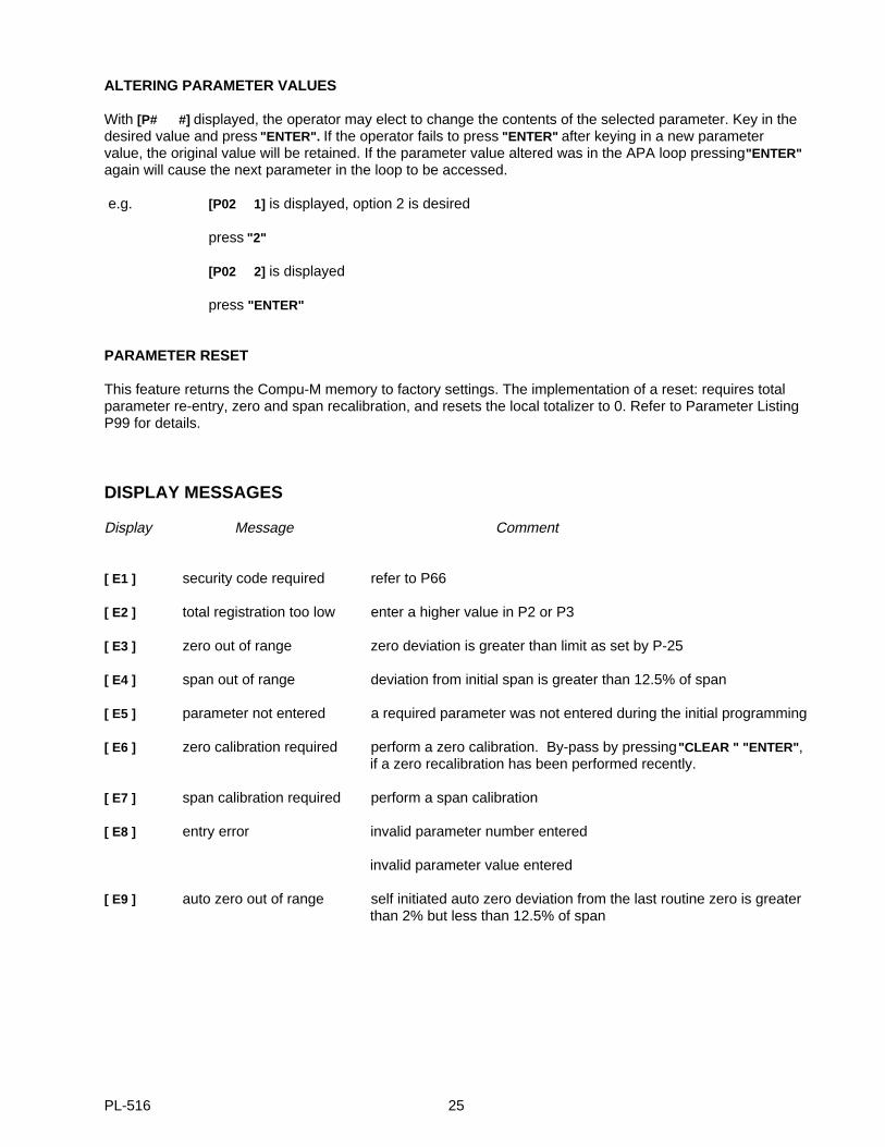
DISPLAY MESSAGES
Display Message Comment
[ E1 ] security code required refer to P66
[ E2 ] total registration too low enter a higher value in P2 or P3
[ E3 ] zero out of range zero deviation is greater than limit as set by P-25
[ E4 ] span out of range deviation from initial span is greater than 12.5% of span
[ E5 ] parameter not entered a required parameter was not entered during the initial programming
[ E6 ] zero calibration required perform a zero calibration. By-pass by pressing "CLEAR " "ENTER" , if a zero recalibration has been performed recently.
[ E7 ] span calibration required perform a span calibration
[ E8 ] entry error invalid parameter number entered
invalid parameter value entered
[ E9 ] auto zero out of range self initiated auto zero deviation from the last routine zero is greater than 2% but less than 12.5% of span
PL-516 25

PL-516 26
APPLICATIONS
BELT SCALE APPLICATION
OPERATION
Input Signals
The Compu-M supplies the excitation for the belt scale load cell(s). The load cell(s) produce an analog mVsignal which is proportional to the load on the scale.
Excitation is also provided for a speed sensor. If used, the speed sensor produces a digital signal at afrequency which is proportional to belt speed.
In cases where a speed sensor is not used, the Compu-M simulates a speed sensor input representing aconstant belt speed which is operator adjustable to suit the particular application.
If the Compu-M is to be utilized with a belt scale that is installed on a variable incline conveyor (such as astacker), an Incline Compensator should be used. The Incline Compensator automatically corrects the loadcell(s) signal variation caused by a change in conveyor incline.
Signal Processing
The Compu-M utilizes the load and speed signals to produce an internal rate signal. Utilizing advancedmicroprocessor technology the Compu-M converts the internal rate signal to provide; display, analog output,remote totalizer contact and rate alarm.
Display Modes
Four operator selectable display modes are available (RATE, TOTAL, LOAD or SPEED ). The modes can bescrolled manually by pressing ‘ALT DISP’, or the Rate and Total automatically by setting P21, auto scroll display.
The Rate, Load, Speed displays, in operator selectable engineering units, are stabilized by the level of dampingprogrammed (P11).
The Rate Display represents the rate at which material is currently conveyed.
The Total Display represents the total amount of material which has passed over the belt scale since the lastCompu-M (local) totalizer reset. The operator may reset this display to zero (0) at any time, depending on theaccess security level programmed, by pressing "RESET TOTAL", "CLEAR" .
The Load Display represents the force currently applied to the belt scale by the weight of the material on the belt.
The Speed Display represents the current belt speed.
PL-516 27
Analog mA Output
This D.C. current output is proportional to the current rate of material throughput and may be utilized foroperating external process monitoring and/or process control equipment. The minimum output correspondingto minimum (usually 0) rate is user selectable (P12) for 0 or 4 ma. The maximum output corresponding tomaximum desired rate is 20mA. The analog mA output may be stabilized by the damping values entered inP11 or P18.
Remote Totalizer Contact
The Compu-M provides a relay contact closure which may be utilized to operate an external device such as aremote totalizer. The on-time duration of the relay contact closure is operator selectable (P16) to suit theexternal device connected.
Alarm
The Compu-M provides a programmable relay for alarm (P20) on material rate, belt speed or auto zero out ofrange. If enabled, the relay is energized under normal operation. Under alarm condition, the relay isde-energized and the display flashes. Upon return to normal operation, the alarm state is cleared and therelay energized. If the relay is programmed for auto zero the alarm is in effect until an auto zero within rangeoccurs, when a calibration is initiated or when the rate exceeds 12% of design.
The relay contacts are accessed via board A, TB2.
INITIAL START UP
When working on a belt scale, ensure that the conveyor is stopped and locked out.
Once installation, interconnection and internal checks have been completed, apply power to the Compu-M.The display should read, [P ].
Reset
Prior to programming, a Compu-M memory reset should be performed.
select P99
press "ENTER"
[P99 0] displayedpress "9" for Master Reset
[P99 9] displayed
press "ENTER" , when the memory reset is complete,
[P ] displayed.
The Compu-M memory has now been cleared of any undesired data and all parameters have been reset to factory values.
PL-516 28
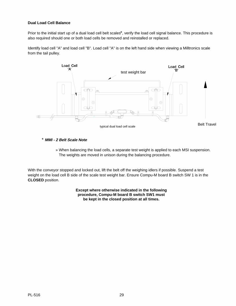
Dual Load Cell Balance
Prior to the initial start up of a dual load cell belt scales*, verify the load cell signal balance. This procedure isalso required should one or both load cells be removed and reinstalled or replaced.
Identify load cell "A" and load cell "B". Load cell "A" is on the left hand side when viewing a Milltronics scalefrom the tail pulley.
* MMI - 2 Belt Scale Note
» When balancing the load cells, a separate test weight is applied to each MSI suspension. The weights are moved in unison during the balancing procedure.
With the conveyor stopped and locked out, lift the belt off the weighing idlers if possible. Suspend a testweight on the load cell B side of the scale test weight bar. Ensure Compu-M board B switch SW 1 is in theCLOSED position.
Except where otherwise indicated in the following procedure, Compu-M board B switch SW1 must
be kept in the closed position at all times.
test weight bar
Belt Traveltypical dual load cell scale
PL-516 29
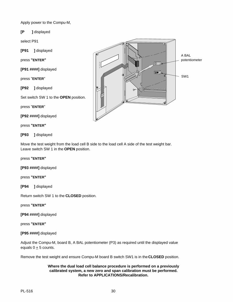
Apply power to the Compu-M,
[P ] displayed
select P91
[P91 ] displayed
press "ENTER"
[P91 ####] displayed
press "ENTER"
[P92 ] displayed
Set switch SW 1 to the OPEN position.
press "ENTER"
[P92 ####] displayed
press "ENTER"
[P93 ] displayed
Move the test weight from the load cell B side to the load cell A side of the test weight bar. Leave switch SW 1 in the OPEN position.
press "ENTER"
[P93 ####] displayed
press "ENTER"
[P94 ] displayed
Return switch SW 1 to the CLOSED position.
press "ENTER"
[P94 ####] displayed
press "ENTER"
[P95 ####] displayed
Adjust the Compu-M, board B, A BAL potentiometer (P3) as required until the displayed value equals 0 + 5 counts.
Remove the test weight and ensure Compu-M board B switch SW1 is in the CLOSED position.
Where the dual load cell balance procedure is performed on a previously calibrated system, a new zero and span calibration must be performed.
Refer to APPLICATIONS/Recalibration.
A BALpotentiometer
SW1
PL-516 30
Programming and Calibration
The following parameters are in the Automatic Parameter Access (APA) loop. Press "ENTER" once to acceptthe current parameter value and proceed to the next parameter. To alter a parameter value, key in the newvalue and press "ENTER" . Press "ENTER" again to advance to the next parameter.
with [P ] displayed
press "ENTER"
[P01 1] displayed, Belt Scale Application
press "ENTER"
[P02 1] displayed, Load Cell Input
press "ENTER"
[P0 1] displayed, Rate Units = MTPH
key in value, 1 = MTPH2 = KG/H3 = LTPH4 = STPH5 = LB/H
press "ENTER"
[P1 0.000] displayed, Design Rate = 0
key in value, (Rate from Design Data Sheet)
press "ENTER"
[P2 1.000] displayed, Local Totalizer Update = every 1 unit.
key in value, (refer to Parameters, P2)
press "ENTER"
[P3 1.000] displayed, Remote Totalizer Update = every 1 unit.
key in value, (refer to Parameter Listing, P3)
press "ENTER"
[P4 0.000] displayed, Belt Speed = 0
key in value, (Belt Speed from Design Data Sheet)
press "ENTER"
[P5 ####] displayed, Speed Constant (refer to Parameter Listing)
key in value, (Speed Constant, only if a speed sensor is utilized)
PL-516 31
press "ENTER"
[P6 0.000] displayed, Belt Length = 0
key in value, (Belt Length, as measured or from Design Data Sheet)
press "ENTER"
[P7 ####] displayed, Test Load = 100% Design Load
key in value, (Test Load, from Design Data Sheet. Refer to the associated belt scale instruction manual.)press "ENTER"
Zero Calibration
If the actual belt speed is 10% or less than the Design Belt Speed (P4), the calibration will be aborted. [oF 0] will be displayed.
Run the empty belt at normal operating speed for some time to limber up the belt (at least 10 minutes).
press "ZERO"
[oo 0] displayed
press "ENTER" , all 4 display mode LED’s will be illuminated,
[oo ####] displayed, wait (time dependent on value of P30)
[od 0.000] displayed, Zero Deviation
press "ENTER"
[oC ####] displayed, Initial Zero Reference Count
Span Calibration
If the actual belt speed is 10% or less than the Design Belt Speed (P4), the calibration will be aborted. [SF 0] will be displayed.
Suspend the Test Weight(s) from the scale calibration weight bracket or place the test chain on the belt.Refer to the associated belt scale instruction manual.
Run the conveyor at normal operating speed.
press "SPAN"
[SP 0] displayed
press "ENTER" , all 4 display mode LED’s will be illuminated and
[SP ####] displayed, wait (time dependent on the value of P30)
PL-516 32
[Sd 0.0000] displayed, Span Deviation
press "ENTER"
[SC ####] displayed, Initial Span Reference Count
Automatic Parameter Access (APA) programming complete. Parameter programming outside of the APA loopmust be directly accessed.
ie : Press "PAR" , press "#" , press "ENTER" , key in new value, press "ENTER" .
Belt Speed Compensation
Run the belt empty for 5 - 10 minutes ensuring that it is completely empty. Select the Belt Speed DisplayMode by pressing "ALT DISP" until the SPEED Display Mode Status LED on the Compu-M front cover isilluminated. If the displayed speed equals the Design Speed, proceed to the optional material test. If not, withthe belt stopped, measure a section of the belt. Run the belt again. Measure the time period required for themeasured length of belt to pass.
measured speed = belt length ( engineering units as selected in P4 to be used ) time
select P17
press "ENTER"
[P17 #] displayed, Dynamic Belt Speed
key in value, (measured belt speed)
press "ENTER"
[P17 #] displayed, Design Belt Speed
If the Compu-M Constant Speed Input is jumpered the preceding steps will have altered the Design Speed(P4). Record the new P4 value on the Programming Chart.
If the Compu-M Speed Input is supplied by a Speed Sensor the preceding steps will have altered the SpeedConstant (P5). Record the new P5 value on the Programming Chart.
In either case above the Compu-M speed display now equals the Actual Speed.
BASIC CALIBRATION COMPLETE PRESS "RUN" TO ENTER THE RUN MODE FOR NORMAL OPERATION
PL-516 33
Optional Material Test
Material tests are performed to verify the accuracy of the Compu-M span calibration. If the material testsindicate a repeatable calibration deviation exists, a Manual Span Adjust (P8) is performed. This procedureautomatically alters the Span calibration and adjusts the Test Load (P7) value accordingly. Subsequent spanrecalibration utilizing the Test Weight or Test Chain will provide more accurate calibration results.
1. Run the belt empty. 2. Perform a zero calibration.3. Record the Compu-M Total Display, (start value).4. Press "RUN" .5. Run material on the belt for 5 minutes minimum. (Ensure the test weight/chain is removed).6. Stop the material feed and run the conveyor empty.7. Record the Compu-M Total Display, (stop value). 8. Subtract the start value from the stop value to determine the Compu-M Total.9. Weigh the material sample, (if the actual material weight is not already known).10. Calculate the span error...
% Span Error = Compu-M Total - Material Sample Weight x 100Material Sample Weight
If the span error is within the accuracy requirements of the system, the material test was a success andnormal operation may be resumed.If the span error is not acceptable, repeat steps 1 through 10 to verify the span error is repeatable. If the spanerror of the second test is considerably different from the span error of the first test (for no apparent reason),consult Milltronics or your local distributor. If the span error is repeatable (the results of both material tests are similar), proceed as follows.
select P8 (Manual Span Adjust)
[P8 A] displayed
key in the calculated % span error (if the result was negative, enter a negative value).
press "ENTER"
[P7 ###] displayed, (adjusted Test Load value, copy this new value onto the Programming Chart)
Repeat steps 1 through 10. The span error should now be within the system accuracy requirements.
Manual Span Adjust complete.
Additional Performance Enhancement
After performing the initial span or after running a material test P10, P11, P12, P13, P14, P16, P17, and P18may be altered to enhance the display readings and rate output of the Compu-M. These direct accessparameters are explained in detail in, Parameters.
PL-516 34
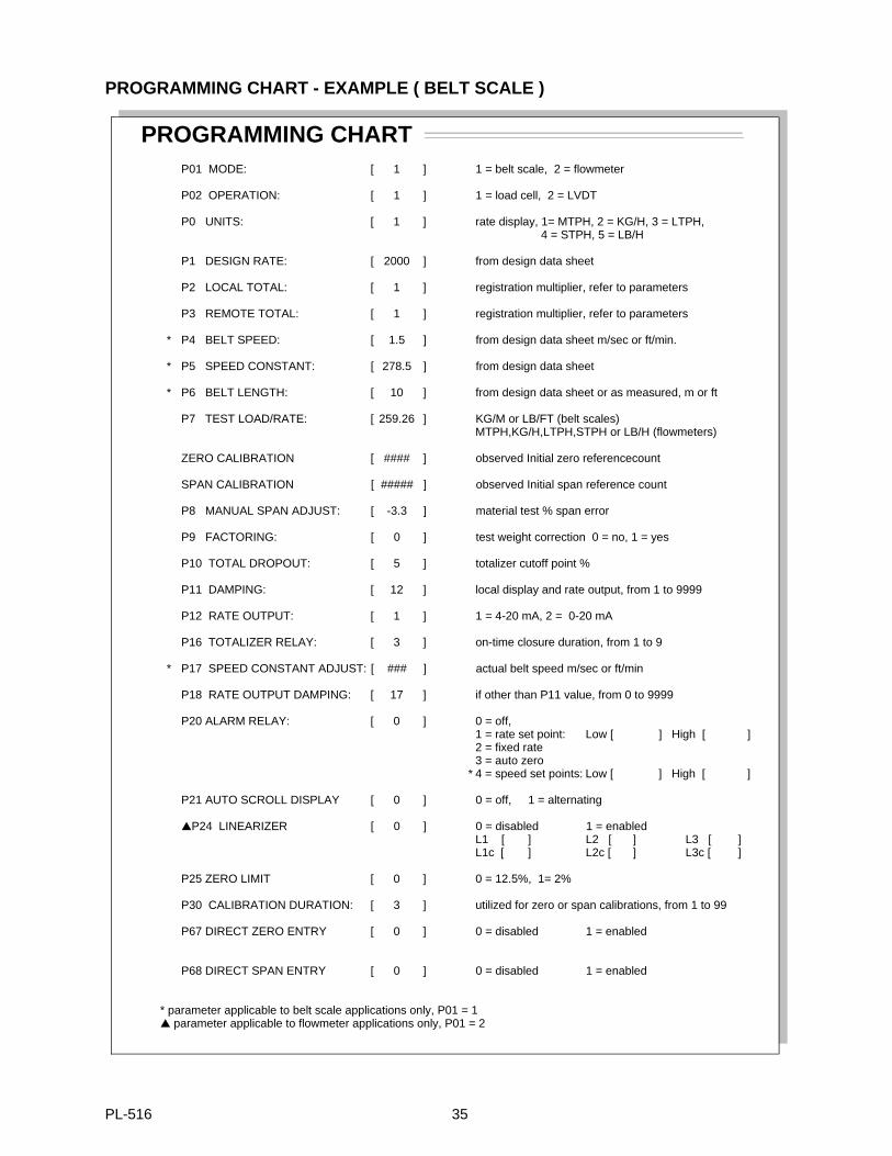
PROGRAMMING CHART - EXAMPLE ( BELT SCALE )
PROGRAMMING CHARTP01 MODE: [ 1 ] 1 = belt scale, 2 = flowmeter
P02 OPERATION: [ 1 ] 1 = load cell, 2 = LVDT
P0 UNITS: [ 1 ] rate display, 1= MTPH, 2 = KG/H, 3 = LTPH, 4 = STPH, 5 = LB/H
P1 DESIGN RATE: [ 2000 ] from design data sheet
P2 LOCAL TOTAL: [ 1 ] registration multiplier, refer to parameters
P3 REMOTE TOTAL: [ 1 ] registration multiplier, refer to parameters
* P4 BELT SPEED: [ 1.5 ] from design data sheet m/sec or ft/min.
* P5 SPEED CONSTANT: [ 278.5 ] from design data sheet
* P6 BELT LENGTH: [ 10 ] from design data sheet or as measured, m or ft
P7 TEST LOAD/RATE: [ 259.26 ] KG/M or LB/FT (belt scales)MTPH,KG/H,LTPH,STPH or LB/H (flowmeters)
ZERO CALIBRATION [ #### ] observed Initial zero referencecount
SPAN CALIBRATION [ ##### ] observed Initial span reference count
P8 MANUAL SPAN ADJUST: [ -3.3 ] material test % span error
P9 FACTORING: [ 0 ] test weight correction 0 = no, 1 = yes
P10 TOTAL DROPOUT: [ 5 ] totalizer cutoff point %
P11 DAMPING: [ 12 ] local display and rate output, from 1 to 9999
P12 RATE OUTPUT: [ 1 ] 1 = 4-20 mA, 2 = 0-20 mA
P16 TOTALIZER RELAY: [ 3 ] on-time closure duration, from 1 to 9
* P17 SPEED CONSTANT ADJUST: [ ### ] actual belt speed m/sec or ft/min
P18 RATE OUTPUT DAMPING: [ 17 ] if other than P11 value, from 0 to 9999
P20 ALARM RELAY: [ 0 ] 0 = off,1 = rate set point: Low [ ] High [ ]2 = fixed rate 3 = auto zero
* 4 = speed set points: Low [ ] High [ ]
P21 AUTO SCROLL DISPLAY [ 0 ] 0 = off, 1 = alternating
P24 LINEARIZER [ 0 ] 0 = disabled 1 = enabledL1 [ ] L2 [ ] L3 [ ]L1c [ ] L2c [ ] L3c [ ]
P25 ZERO LIMIT [ 0 ] 0 = 12.5%, 1= 2%
P30 CALIBRATION DURATION: [ 3 ] utilized for zero or span calibrations, from 1 to 99
P67 DIRECT ZERO ENTRY [ 0 ] 0 = disabled 1 = enabled
P68 DIRECT SPAN ENTRY [ 0 ] 0 = disabled 1 = enabled
* parameter applicable to belt scale applications only, P01 = 1 parameter applicable to flowmeter applications only, P01 = 2
PL-516 35
RECALIBRATION
Design Changes
Some parameters interact with others. After altering a parameter value, check all other parameter values. TheCompu-M may have altered one or more interacting parameters automatically. Record all parameter valuechanges on the Design Data Sheet and Programming Chart for future reference.
Recalibration
To maintain Belt Scale accuracy, periodic zero and span recalibration is recommended. Recalibrationrequirements are highly dependent upon the severity of the application operating conditions. Perform frequentchecks initially, then as time and experience dictate, the frequency of these checks may be reduced. Alwaysrecord any deviations experienced for future reference.
Routine Zero
To perform a routine zero recalibration, run the empty belt for 5 - 10 minutes.
press "ZERO"
[oo ####] displayed, Current Zero Count
press "ENTER"
[oo ####] displayed, wait (time dependent upon the value of P30)
[od ####] displayed, Zero Deviation in %
press "ENTER"
[oC ####] displayed, New Zero Count, zero complete
If [oo E3] displayed; routine zero attempt aborted, zero deviation is greater than the limit as set by P-25.
The [E3] Display Message normally indicates a mechanical problem. Investigate the cause of the deviation and make the necessary correction. Retry the zero calibration.
If the deviation is determined to be acceptable, perhaps because of intended mechanical changes to the system, set P77 to 1 to invoke a new " Initial Zero Calibration Reference".
Any future deviation will be based on this new Zero.
PL-516 36

Initial Zero
select P77
press "ENTER"
[P77 0] displayed
press "1"
press "ENTER"
[P77 1] displayed
press "ENTER"
[oo ####] displayed, wait (time dependent upon the value of P30)
[od 0.000] displayed
press "ENTER"
[oC ####] displayed, New Zero Count, zero calibration complete
Direct Zero Entry
Direct entry is intended for use when replacing software or hardware and it is not convenient to perform an initial zero at that time.
select P67
press "ENTER"
[P67 0] displayed
press "1"
[P67 1] displayed
press "ENTER"
[Pc 0.] displayed e.g. value ’0’ after a P99 reset
enter the recorded zero reference of previous zero (#####)
press "ENTER"
[oC #####] displayed, new zero count, entry complete
PL-516 37
Routine Span
To perform a routine span recalibration, stop the conveyor belt and suspend the test weight from the scalecalibration weight bracket or place the test chain on the belt. Refer to associated scale manual.
Run the belt, empty (except for the test chain, if used) at normal operating speed
press "SPAN"
[SP ####] displayed, Current Span Count
press "ENTER"
[SP ####] displayed, wait (Time dependent on the value of P30)
[Sd ####] displayed, Span Deviation in %
press "ENTER"
[SC ####] displayed, New Span Count, span complete
If [SP E4] displayed; routine span attempt aborted, deviation from initial span calibration was greater than12.5% of span.
An [E4] Display Message normally indicates a mechanical problem. Investigate the cause of the deviation and make the necessary correction. Retry the span calibration.
If the deviation is determined to be acceptable, perhaps as the result of an intended mechanical change to the system, set P88 to 1 to invoke a new " Initial Span Calibration Reference". Further deviations will be based on this new Span.
Initial Span
select P88
press "ENTER"
[P88 0] displayed
press "1"
press "ENTER"
[P88 1] displayed
Press "ENTER"
[SP ####] displayed, wait (time dependent on the value of P30)
[Sd 0.000] displayed
press "ENTER"
[SC ####] displayed, New Span Count, span calibration complete
Perform a material test, if desired, to verify the new calibration accuracy.
PL-516 38
Direct Span Entry
Direct entry is intended for use when replacing software or hardware and it is not convenient to perform an initial span at that time.
select P68
press "ENTER"
[P68 0] displayed
press "1"
press "ENTER"
[P68 1] displayed
press "ENTER"
[Pc 0.] displayed e.g. value after a P99 reset
enter the recorded span reference count of the previous span (#####)
press "ENTER"
[SC #####] displayed, new span count, entry complete
PL-516 39

Self Initiated Auto Zero
Where frequent minor zero deviations are expected, the Compu-M self initiated auto zero feature may beutilized to perform an automatic zero calibration whenever the material flow ceases.
Connect a dry contact activated by a material prefeed control device such as a prefeed motor, material controlgate, or valve to board B 1TB-1 and 2 of the Compu-M. The contact must be closed while the materialprefeed is stopped.
While this contact is closed and after sensing an empty running belt the Compu-M will perform an auto zero. Ifthe difference between the auto zero and the last operator initiated (routine) zero calibration is less than 2% ofthe design Rate (P1), the Compu-M will accept the auto zero results.
If the difference between the auto zero and the last routine zero is greater than 2% of the design Rate, theCompu-M will display [E9 - auto zero out of range] temporarily, reject the results of the auto zero attempt andthen resume normal operation.
If the alarm relay is set for auto zero (P20 = 3) , the relay is de-energized and the display flashes. The alarmis in effect until an ’auto zero’ within range occurs, when a calibration is initiated, or when the rate exceeds12% of design.
If the Compu-M displays [E9] after repeated auto zero attempts, the operator should perform a routine zerocalibration. Future auto zero attempts will be referenced to this new zero calibration.
The Compu-M will continue to perform auto zero calibrations until the prefeed activated contact connected toTB1-1 and 2 is open. Any material totalized during a self initiated auto zero is added to the Compu-M totaland the remote total. The analog mA output will respond to any material measured during a self initiated auto zero.
PL-516 40
APPLICATIONS (Cont’d)
SOLIDS FLOWMETER APPLICATION
OPERATION
Input Signals
The Compu-M supplies the excitation for the flowmeter transducing element, (LVDT or load cell). Materialflowing through the flowmeter is directed toward a sensing plate. The sensing plate is designed to deflecthorizontally proportional to material flow. This horizontal deflection is applied to the transducing elementwhich produces a signal proportional to material flow.
Signal Processing
The Compu-M utilizes the material flow signal to produce an internal rate signal. Utilizing advancedmicroprocessor technology, the Compu-M converts the internal rate signal to provide display, analog output,remote totalizer contact and rate alarm.
Display Modes
Two operator selectable display modes are available (RATE or TOTAL). The modes can be scrolled manuallyby pressing ’ALT DISP’ or automatically by setting P21, auto scroll display.
The Rate Display represents the rate at which material is currently flowing through the system. This display, inoperator selectable engineering units, may be stabilized by the level of damping programmed, (P11).
The Total Display represents the total amount of material which has passed through the flowmeter since thelast Compu-M (local) totalizer reset. The operator may reset this display to zero (0) at any time, dependingupon the access security level programmed, by pressing "RESET TOTAL", "CLEAR".
Analog mA Output
This DC current output is proportional to the current rate of material flow and may be utilized for operatingexternal process monitoring and/or process control equipment. The minimum output corresponding tominimum (usually 0) flow is user selectable (P12) for 0 or 4 ma. The maximum output corresponding tomaximum desired material flow is 20mA. The analog mA output is stabilized by the damping values entered inP11 or P18.
Remote Totalizer Contact
The Compu-M provides a relay contact closure which may be utilized to operate an external device such as aremote mounted totalizer. The on-time duration of the relay contact closure is operator selectable (P16) to suitthe external device connected.
PL-516 41
Alarm
The Compu-M provides a programmable relay for alarm (P20) on material rate, or auto zero out of range. Ifenabled, the relay is energized under normal operation. Under alarm condition, the relay is de-energized andthe display flashes. Upon return to normal operation, the alarm state is cleared and the relay energized. If therelay is programmed for auto zero the alarm is in effect until an auto zero within range occurs, when acalibration is initiated or when the rate exceeds 12% of design.
The relay contacts are accessed via board A, TB2.
TEST RATE
The Test Rate (P7) is the flowrate chosen for calibration purposes. The test rate is a simulated materialflowrate created by attaching a weight in such a manner as to apply a horizontal force to the flowmetersensing plate. This weight is referred to as the test weight. Refer to the associated flowmeter instructionmanual for assistance with the calculation and application of the test weight required to produce a desired testrate, or conversely, the test rate produced by a known test weight.
INITIAL START UP
When working on a flowmeter, ensure that the material prefeed has been stopped and locked out.
Once installation, interconnection and internal checks have been completed, apply power to the Compu-M.The display should read, [P ].
Reset
Prior to programming, a Compu-M memory reset should be performed.
select P99
press "ENTER"
[P99 0] displayed
press "9" for Master Reset
[P99 9] displayed
press "ENTER" , memory reset complete[P ] displayed.
The Compu-M memory has now been cleared of any undesired data and all parameters have been reset tofactory values.
PL-516 42
Programming And Calibration
The following parameters are in the Automatic Parameter Access (APA) loop. Press "ENTER" once to acceptthe current parameter value and proceed to the next parameter. To alter a parameter value, key in the newvalue and press "ENTER" . Press "ENTER" again to advance to the next parameter.
with [P ] displayed
press "ENTER"
[P01 1] displayed, Belt Scale Application
press "2"
press "ENTER"
[P01 2] displayed, Flowmeter Application
press "ENTER"
[P02 1] displayed, Load Cell Input
key in value, 1 = Load Cell 2 = LVDT
press "ENTER"
[P0 1] displayed, Rate Units = MTPH
key in value, 1 = MTPH2 = KG/H3 = LTPH4 = STPH5 = LB/H
press "ENTER"
[P1 0.000] displayed, Design Rate = 0
key in value, Rate from Design Data Sheet or Order Acknowledgement
press "ENTER"
[P2 1.000] displayed, Local Totalizer Update = every 1 unit.key in value, (refer to Parameters, P2)
press "ENTER"
[P3 1.000] displayed, Remote Totalizer Update = every 1 unit.
key in value, (refer to Parameters, P3)
press "ENTER"
[P7 ####] displayed, Test Rate, 100% of Design Rate
key in value, from Design Data Sheet or refer to the associated flowmeter instruction manual.
press "ENTER"
PL-516 43
Zero Calibration
With the material flow stopped and Test Weight removed,
press "ZERO"
[oo 0] displayed
press "ENTER" , all 4 display mode LED’s will be illuminated,
[oo ####] displayed momentarily then,
[od 0.000] displayed, Zero Deviation
press "ENTER"
[oC ####] displayed, Initial Zero Reference Count
Span Calibration
Apply the Test Weight as described in the associated flowmeter instruction manual.
press "SPAN"
[SP 0] displayed
press "ENTER" , all 4 display mode LED’s will be illuminated and
[SP ####] displayed momentarily then,
[Sd 0.0000] displayed, Span Deviation
press "ENTER"
[SC ####] displayed, Initial Span Reference Count
Remove the test weight.
BASIC CALIBRATION COMPLETEPRESS "RUN" TO ENTER THE RUN MODE FOR NORMAL OPERATION
Automatic Parameter Access (APA) programming complete. Further programming, if desired, to enhance theperformance of the Compu-M requires parameter programming outside of the APA loop. These parametersmust be directly accessed.
ie. Press "PAR" , press "#", press "ENTER" , key in new value, press "ENTER".
PL-516 44
Optional Material Test
Material tests are performed to verify the accuracy of the Compu-M span calibration. If the material testsindicate a repeatable calibration deviation exists, a Manual Span Adjust (P8) is performed. This procedureautomatically alters the Span calibration and adjusts the Test Rate (P7) value accordingly. Subsequent spanrecalibration utilizing the Test Weight will provide more accurate calibration results.
1. Stop the material flow.2. Perform a zero calibration.3. Record the Compu-M Total Display, (start value).4. Press "RUN" .5. Run material through the flowmeter for 5 minutes minimum. (Ensure the test weight is removed).6. Stop the material flow.7. Record the Compu-M Total Display, (stop value).8. Subtract the start value from the stop value to determine the Compu-M Total.9. Weigh the material sample, (if the actual material weight is not already known).
10. Calculate the span error...
% Span Error = Compu-M Total - Material Sample Weight x 100 Material Sample Weight
If the span error is within the accuracy requirements of the system, the material test was a success andnormal operation may be resumed.
If the span error is not acceptable, repeat steps 1 through 10 to verify the span error is repeatable. If the spanerror of the second test is considerably different from the span error of the first test (for no apparent reason),consult Milltronics or your local distributor.
If the span error is repeatable (the results of both material tests are similar), proceed as follows.
select P8 (Manual Span Adjust)
[P8 A] displayed
key in the calculated % span error (if the result was negative, enter a negative value).
press "ENTER"
[P7 ###] displayed, (adjusted Test Rate value, copy this new value onto the Programming Chart)
Repeat steps 1 through 10. The span error should now be within the system accuracy requirements.
Manual Span Adjust complete.
Linearization
Where the flowrate reported by the Compu-M is non-linear due to material flow characteristics, compensationis achieved by enabling and programming the linearization parameter, P24.
To verify that the cause of the non-linearity is not mechanical:
- stop the process- apply the various test weights to the flowmeter to verify mechanical linearity. If the reported rate is non-linear, a mechanical problem is indicated. Refer to the associated flowmeter manual.
)(
PL-516 45
If non-linearity due to material flow characteristics is still suspect, apply linearization.- perform a zero calibration- perform a span calibration at 90 to 100% of design rate- perform material tests at 90 to 100% of design rate- perform a manual span adjustment if required- perform material tests at 1 to 3 intermediary flowrates where compensation is required.
Up to three compensation points, at least 10% apart, can be programmed between 10 and 90% of the design rate value, P1, in the units of P0. The points should be programmed at operating
flowrates where non-linearity is evidenced.
- calculate the percentage compensation for each flowrate tested.
% compensation = actual weight - totalized weigh t x 100totalized weight
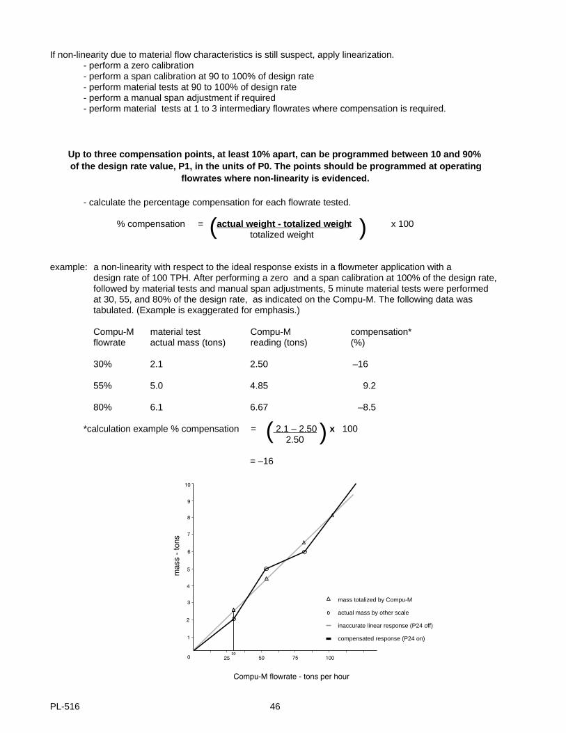
example: a non-linearity with respect to the ideal response exists in a flowmeter application with a design rate of 100 TPH. After performing a zero and a span calibration at 100% of the design rate, followed by material tests and manual span adjustments, 5 minute material tests were performed at 30, 55, and 80% of the design rate, as indicated on the Compu-M. The following data was tabulated. (Example is exaggerated for emphasis.)
Compu-M material test Compu-M compensation*flowrate actual mass (tons) reading (tons) (%)
30% 2.1 2.50 –16
55% 5.0 4.85 9.2
80% 6.1 6.67 –8.5
*calculation example % compensation = 2.1 – 2.50 x 100 2.50
= –16
( )
( )
mass totalized by Compu-M
actual mass by other scale
inaccurate linear response (P24 off)
compensated response (P24 on)
PL-516 46

select P24
press "ENTER"
[P24 0] displayed
press "1"
press "ENTER"
[P24 1] displayed
press "ENTER"
[L1 0.] displayed
press "30"
press "ENTER"
Press "ENTER"
[L1c 0.00] displayed
press "–16"
press "ENTER"
[L1c –16.0]
press "ENTER"
[L2 0.00]...
L3c 0.00]
press "– 8.5"
press "ENTER"
[L3c – 8.5]
press "ENTER"
[L1 30.0] displayed
Upon returning to Run Mode , compensation is active until P24 is set to 0.
PL-516 47
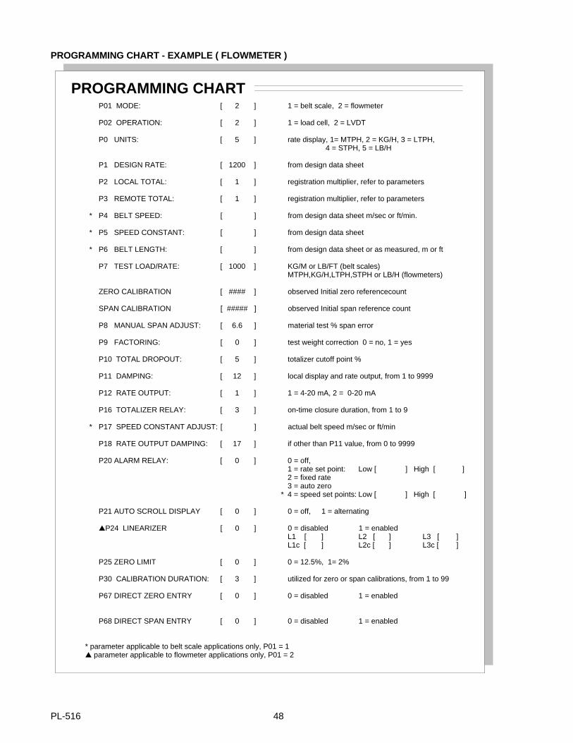
PROGRAMMING CHART - EXAMPLE ( FLOWMETER )
PROGRAMMING CHARTP01 MODE: [ 2 ] 1 = belt scale, 2 = flowmeter
P02 OPERATION: [ 2 ] 1 = load cell, 2 = LVDT
P0 UNITS: [ 5 ] rate display, 1= MTPH, 2 = KG/H, 3 = LTPH, 4 = STPH, 5 = LB/H
P1 DESIGN RATE: [ 1200 ] from design data sheet
P2 LOCAL TOTAL: [ 1 ] registration multiplier, refer to parameters
P3 REMOTE TOTAL: [ 1 ] registration multiplier, refer to parameters
* P4 BELT SPEED: [ ] from design data sheet m/sec or ft/min.
* P5 SPEED CONSTANT: [ ] from design data sheet
* P6 BELT LENGTH: [ ] from design data sheet or as measured, m or ft
P7 TEST LOAD/RATE: [ 1000 ] KG/M or LB/FT (belt scales)MTPH,KG/H,LTPH,STPH or LB/H (flowmeters)
ZERO CALIBRATION [ #### ] observed Initial zero referencecount
SPAN CALIBRATION [ ##### ] observed Initial span reference count
P8 MANUAL SPAN ADJUST: [ 6.6 ] material test % span error
P9 FACTORING: [ 0 ] test weight correction 0 = no, 1 = yes
P10 TOTAL DROPOUT: [ 5 ] totalizer cutoff point %
P11 DAMPING: [ 12 ] local display and rate output, from 1 to 9999
P12 RATE OUTPUT: [ 1 ] 1 = 4-20 mA, 2 = 0-20 mA
P16 TOTALIZER RELAY: [ 3 ] on-time closure duration, from 1 to 9
* P17 SPEED CONSTANT ADJUST: [ ] actual belt speed m/sec or ft/min
P18 RATE OUTPUT DAMPING: [ 17 ] if other than P11 value, from 0 to 9999
P20 ALARM RELAY: [ 0 ] 0 = off,1 = rate set point: Low [ ] High [ ]2 = fixed rate 3 = auto zero
* 4 = speed set points: Low [ ] High [ ]
P21 AUTO SCROLL DISPLAY [ 0 ] 0 = off, 1 = alternating
P24 LINEARIZER [ 0 ] 0 = disabled 1 = enabledL1 [ ] L2 [ ] L3 [ ]L1c [ ] L2c [ ] L3c [ ]
P25 ZERO LIMIT [ 0 ] 0 = 12.5%, 1= 2%
P30 CALIBRATION DURATION: [ 3 ] utilized for zero or span calibrations, from 1 to 99
P67 DIRECT ZERO ENTRY [ 0 ] 0 = disabled 1 = enabled
P68 DIRECT SPAN ENTRY [ 0 ] 0 = disabled 1 = enabled
* parameter applicable to belt scale applications only, P01 = 1 parameter applicable to flowmeter applications only, P01 = 2
PL-516 48
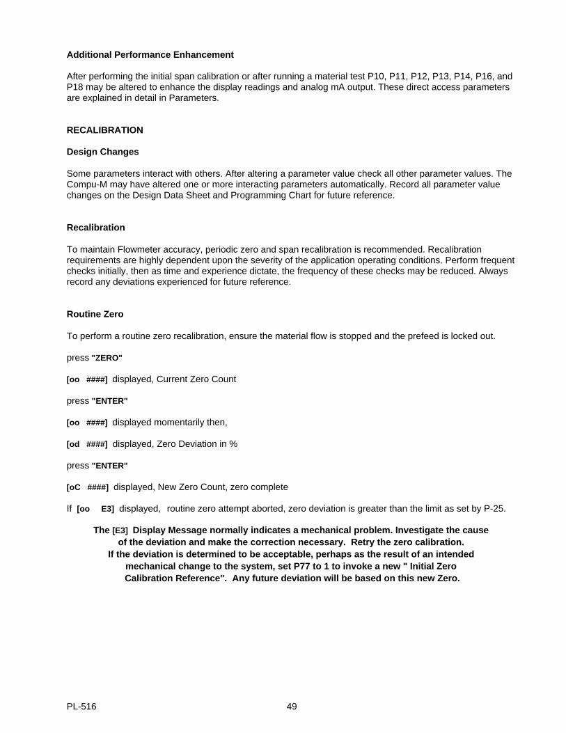
Additional Performance Enhancement
After performing the initial span calibration or after running a material test P10, P11, P12, P13, P14, P16, andP18 may be altered to enhance the display readings and analog mA output. These direct access parametersare explained in detail in Parameters.
RECALIBRATION
Design Changes
Some parameters interact with others. After altering a parameter value check all other parameter values. TheCompu-M may have altered one or more interacting parameters automatically. Record all parameter valuechanges on the Design Data Sheet and Programming Chart for future reference.
Recalibration
To maintain Flowmeter accuracy, periodic zero and span recalibration is recommended. Recalibrationrequirements are highly dependent upon the severity of the application operating conditions. Perform frequentchecks initially, then as time and experience dictate, the frequency of these checks may be reduced. Alwaysrecord any deviations experienced for future reference.
Routine Zero
To perform a routine zero recalibration, ensure the material flow is stopped and the prefeed is locked out.
press "ZERO"
[oo ####] displayed, Current Zero Count
press "ENTER"
[oo ####] displayed momentarily then,
[od ####] displayed, Zero Deviation in %
press "ENTER"
[oC ####] displayed, New Zero Count, zero complete
If [oo E3] displayed, routine zero attempt aborted, zero deviation is greater than the limit as set by P-25.
The [E3] Display Message normally indicates a mechanical problem. Investigate the cause of the deviation and make the correction necessary. Retry the zero calibration.
If the deviation is determined to be acceptable, perhaps as the result of an intended mechanical change to the system, set P77 to 1 to invoke a new " Initial Zero Calibration Reference". Any future deviation will be based on this new Zero.
PL-516 49
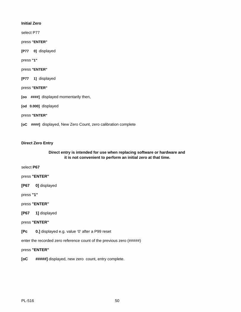
Initial Zero
select P77
press "ENTER"
[P77 0] displayed
press "1"
press "ENTER"
[P77 1] displayed
press "ENTER"
[oo ####] displayed momentarily then,
[od 0.000] displayed
press "ENTER"
[oC ####] displayed, New Zero Count, zero calibration complete
Direct Zero Entry
Direct entry is intended for use when replacing software or hardware and it is not convenient to perform an initial zero at that time.
select P67
press "ENTER"
[P67 0] displayed
press "1"
press "ENTER"
[P67 1] displayed
press "ENTER"
[Pc 0.] displayed e.g. value ‘0’ after a P99 reset
enter the recorded zero reference count of the previous zero (#####)
press "ENTER"
[oC #####] displayed, new zero count, entry complete.
PL-516 50
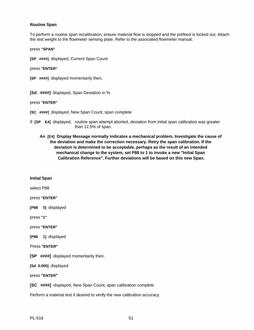
Routine Span
To perform a routine span recalibration, ensure material flow is stopped and the prefeed is locked out. Attachthe test weight to the flowmeter sensing plate. Refer to the associated flowmeter manual.
press "SPAN"
[SP ####] displayed, Current Span Count
press "ENTER"
[SP ####] displayed momentarily then,
[Sd ####] displayed, Span Deviation in %
press "ENTER"
[SC ####] displayed, New Span Count, span complete
If [SP E4] displayed, routine span attempt aborted, deviation from initial span calibration was greater than 12.5% of span.
An [E4] Display Message normally indicates a mechanical problem. Investigate the cause of the deviation and make the correction necessary. Retry the span calibration. If the
deviation is determined to be acceptable, perhaps as the result of an intended mechanical change to the system, set P88 to 1 to invoke a new "Initial Span Calibration Reference". Further deviations will be based on this new Span.
Initial Span
select P88
press "ENTER"
[P88 0] displayed
press "1"
press "ENTER"
[P88 1] displayed
Press "ENTER"
[SP ####] displayed momentarily then,
[Sd 0.000] displayed
press "ENTER"
[SC ####] displayed, New Span Count, span calibration complete
Perform a material test if desired to verify the new calibration accuracy.
PL-516 51
Direct Span Entry
Direct entry is intended for use when replacing software or hardware and it is not convenient to perform an initial span at that time.
select P68
press "ENTER"
[P68 0] displayed
press "1"
press "ENTER"
[P68 1] displayed
press "ENTER"
[Pc 0.] displayed e.g. value ’0’ after a P99 reset
enter the recorded span reference count of the previous span (#####)
press "ENTER"
[SC #####] displayed, new span count, entry complete
Self Initiated Auto Zero
Where frequent minor zero deviations are expected, the Compu-M self initiated auto zero feature may beutilized to perform an automatic zero calibration whenever the material flow ceases.
Connect a dry contact activated by a material prefeed control device such as a prefeed motor, material controlgate, or valve to board B 1TB-1 and 2 of the Compu-M. The contact must be closed while the material prefeedis stopped.
While this contact is closed and after sensing no material flow through the flowmeter, the Compu-M willperform an auto zero. If the difference between the auto zero and the last operator initiated (routine) zerocalibration is less than 2% of the design Rate (P1), the Compu-M will accept the auto zero results.
If the difference between the auto zero and the last routine zero is greater than 2% of the design Rate, theCompu-M will display [E9 - auto zero out of range] temporarily, reject the results of the auto zero attempt andthen resume normal operation.
If the alarm relay is set for auto zero (P20 =3), the relay is de-engerized and the display flashes. The alarm isin effect until an auto zero within range occurs, when a calibration is initiated, or when the rate exceeds 12%of design.
If the Compu-M displays [E9] after repeated auto zero attempts, the operator should perform a routine zerocalibration. Future auto zero attempts will be referenced to this new zero calibration.
The Compu-M will continue to perform auto zero calibrations until the prefeed activated contact connected toTB1-1 and 2 is open. Any material totalized during a self initiated auto zero is added to the Compu-M total andthe remote total. The analog mA output will respond to any material measured during a self initiated auto zero.
PL-516 52
PARAMETERS
GENERAL
(F) indicates parameters’ factory setting, where applicable
(V) indicates parameter can be viewed only.
PARAMETERS
P01 Mode Select
Defines the type of application. The Compu-M selects the appropriate Automatic Parameter Access (APA)software routine based on the value entered.
enter: 1 = belt scale (F)2 = flowmeter
P02 Operation
Defines the type of transducing element utilized to provide the load signal input to the Compu-M.
enter: 1 = load cell (F)2 = LVDT
P0 Rate Units
Defines the desired Rate Display engineering units of measure.
enter: 1 = MTPH, metric tons per hour (F) 1MTPH = 1000 KG/H2 = KG/H, kilograms per hour 1LTPH = 2240 LB/H3 = LTPH, long tons per hour 1STPH = 2000 LB/H4 = STPH, short tons per hour5 = LB/H, pounds per hour
Rate, Belt Speed and Belt Length (P1,P4,and P6) parameter values are not automaticallyconverted if the previously entered Rate Units (P0) are changed. After altering the Rate
Units, converted values must be entered manually for each of these parameters.
P1 Rate
Defines the rate of material flow which will produce the maximum Analog mA Output of 20 mA.
enter: Design Rate from Design Data Sheet (F = 0.000)
PL-516 53
P2 Local Totalizer
Defines the amount of material to be registered by the Compu-M prior to initiating an internal totalizer update.The weight unit portion of the Rate Unit (P0) selected is assumed. (F = 1)
P2 Value Total Display # of Weight Units
enter: .001 = ####.### = thousandths.01 = #####.## = hundredths.1 = ######.# = tenths 1 = ######## = units (F = 1.000)
10 = #######0 = tens100 = ######00 = hundreds
1000 = #####000 = thousands
If the value selected is too low, the Compu-M will display [E2] .Enter a higher value.
P3 Remote Total
Defines the amount of material to be registered by the Compu-M prior to initiating a relay contact closure whichmay be utilized for remote totalization. The weight unit portion of the Rate Unit (P0) selected is assumed.
weight units contact closures
enter: .001 = 1 .01 = 1 .1 = 1 1 = 1 10 = 1 100 = 11000 = 1
If the value selected is too low, the Compu-M will display [E2] .Enter a higher value.
P4 Belt Speed (Belt Scale Applications Only)
Defines the Design Speed of the conveyor belt. After initial calibration, belt speed adjustments may be enteredvia P17 to avoid performing a new initial zero and span calibration.
The speed units are assumed to be:
metres/sec, if P0 = 1 (MTPH)2 (KG/H)
feet/min, if P0 = 3 (LTPH)4 (STPH)5 (LB/H)
enter: Design Belt Speed from Design Data Sheet. (F = 0.000)
PL-516 54
P5 Speed Constant (Belt Scale, Applications Only)
Defines the constant value the Compu-M must multiply to the Speed Sensor output frequency to establish thecurrent belt speed.
If a Speed Sensor is not utilized TB1-13,14 must be jumpered. The Compu-M automatically sets this value to 100. Do not alter this value, proceed to P6.
If a Speed Sensor is utilized, the jumper across TB1-13,14 must be removed.
enter: Design Constant from Design Data Sheet. (F = 0.000)OR
The resultant value of the following calculation.
speed constant = Speed Sensor pulses per rev* = pulses/m or pulses/ftpulley circumference (m or ft)/rev
* see Speed Sensor nameplate or consult Milltronics
P6 Belt Length (Belt Scale Applications Only)
Defines the length of the conveyor belt which passes over the belt scale. The belt length units are assumed to be:
metres, if P0 = 1 (MTPH)2 (KG/H)
feet, if P0 = 3 (LTPH)4 (STPH)5 (LB/H)
enter: Belt Length from Design Data Sheet or
Measured Belt Length (F = 0)
P7 Test Load/Rate
Test Load (Belt Scale Applications Only)
Defines the load to be registered by the Compu-M when the Test Chain or Test Weight is applied to the BeltScale. Enter the value that is indicated on the Design Data sheet. Entering "0" or performing a Reset willreturn the Test Load to the 100% Design Load factory value.
The Test Load Units are assumed to be:
kg/m if P0 = 1 (MTPH)2 (KG/H)
lb/ft if P0 = 3 (LTPH)4 (STPH)5 (LB/H)
enter: Test Load, as determined (F = 100% Design Load)
PL-516 55

Test Rate (Flowmeter Applications Only)
Defines the desired Rate to be registered by the Compu-M when the Test Weight is applied to the flowmeter.
Refer to the associated flowmeter instruction manual for assistance with calibration procedures, and TestWeight or Test Rate calculations.
Enter the desired Test Rate as determined by the preceding calculation.
Entering "0" or performing a Reset will restore the Test Rate to the 100% Design Rate default value.
enter: Test Rate, as determined, (F = 100% Design Rate)
P8 Manual Span Adjust
Permits span calibration error correction, and automatically adjusts the current Test Load/Rate value.
This is accomplished by performing material tests and entering the span error (in percent). Refer to theappropriate Belt Scale Applications or Flowmeter Applications section for instructions.
enter: % Span Error, (as determined).
P9 Factoring
Establishes the Test Load/Rate (P7) value of the applied calibration reference, based on the current Compu-M Span calibration.
This feature may be used, to establish the Test Load/Rate (P7) value of a new or otherwise unknown TestWeight, based on the Compu-M Span calibration results obtained from the old Test Weight.
Before initiating the Factoring process:
» Access the Test Load/Rate (P7) parameter and record the display value associated with the Test Weight(s) used to perform the current Span calibration.» Stop the material flow. (For belt scales, the belt must be running empty.)» With the Test Weight(s) removed, perform a Zero calibration.» Apply the new Test Weight(s).
During the Factoring process, the current Span count is displayed momentarily.
If [P9 E6] is displayed, refer to Programming/Display Messages.
When Factoring is complete, the Test Load/Rate (P7) value of the new Test Weight(s) is displayed. Copy thenew P7 value to the Programming Chart.
Ensure the appropriate Test Load/Rate (P7) value is entered, before performing subsequent Span calibrationswith the old or new Test Weight(s).
enter : 0 = Factoring not required (F)1 = initiate Factoring procedure
PL-516 56
P10 Total Dropout %
Defines the limit, in percentage of the design rate, below which material rates will not be totallized. A value ofzero will permit the Compu-M to count up or down. Relay contact closures for remote totalization will notcontinue until the Compu-M totalized value regains the amount by which it counted down.
enter: limit in percentage of design rate (F = 3.000)
P11 Damping
Defines the level of damping to be applied to the Compu-M local display values and the Analog mA Output.The range of possible values is 1 to 9999 with values of 1 to 50 being typical operating values. The greater thedamping value, the slower the Compu-M displays and analog output will respond to a change in Rate. Refer toP18 for additional Analog mA Output damping.
enter: Damping, as determined, (F = 1.000)
P12 Rate Output
Defines the span of the Analog mA Output which corresponds proportionally to the material rate registered bythe Compu-M.
enter: 1 = 4 - 20 mA (F)2 = 0 - 20 mA
P13 Minimum Output Adjust
Permits limited adjustment of the Compu-M minimum Rate Output (as selected by P12). This adjustment maybe used to match the minimum input required by the attached external device. e.g. mA meter.
The following display values are not crucial but represent typical Compu-M displays. If P12 = 1, (4 mA min.output) the Compu-M will display a value ≅ 600. If P12 = 2, (0 mA min. output) the Compu-M will display avalue ≅ 0.
To increase the output press "4" . To decrease the output press "8" . The Compu-M display value will increaseor decrease in relation to the change in the analog mA output.
e.g. P12 = 1select P13press "ENTER"P13 [666] displayedexternal meter reads 3.8 mApress "4" to increase the displayed value until 4.0 mA is displayed on the external meter.press "ENTER"
PL-516 57
P14 Maximum Output Adjust
Permits limited adjustment of the Compu-M maximum Analog mA Output, 20 mA. This adjustment may beused to match the maximum input required by the attached external device. e.g. mA meter.
When this parameter is accessed the Compu-M will display a value ≅ 3300, the mA output will be 20 mA. To increase the output press "4" . To decrease the output press "8" . The Compu-M display will increase ordecrease in relation to the change in the analog mA output.
e.g. select P14press "ENTER" P14 [3325] displayedexternal meter displays 20.2 mApress "8" to decrease the displayed value until 20.0 mA is displayed on the external meter.press "ENTER"
P15 Diagnostic Meter (V)
Activates the Compu-M input signal measurement functions. To advance to the next function press "ENTER" .
[P15U ###] displayed, range = 0 to 3.98 Volts DC
The value displayed is proportional to the input level supplied by the load cell(s) or the LVDT.
[F #####] displayed, range = 0 to 131,072 counts.
High resolution reference value display, proportional to load cell or LVDT input signal levels.
* [P15A ####] displayed, Load Cell A input in mV (P02=1).
* [P15b ####] displayed, Load Cell B input in mV (P02=1).
select P15
[P15 ] displayed.
press "ENTER"
[P15U ###] displayed.
press "ENTER"
[F #####] displayed.
press "ENTER"
* [P15A ####] displayed.
press "ENTER"
* [P15b ####] displayed.
* Load Cell applications only, (P02=1)
PL-516 58
P16 Remote Totalizer Relay Closure
Defines the on-time duration of the remote totalizer relay contact closure. The on/off cycle time for this relay isautomatically determined by the operator entered values of Rate (P1) and Remote Total (P3). To determinethe on-time duration required, refer to the specifications stated by the manufacturer of the remote totalizer (orother device) to be utilized. If the combination of the values entered in P1, P3, and P16 exceed the operatinglimits of the system the Compu-M will display, [E2] , indicating the value of P3 should be increased.
1 = 32 msec 6 = 192 msec2 = 64 msec 7 = 224 msec3 = 96 msec 8 = 256 msec4 = 128 msec 9 = 288 msec5 = 160 msec
enter: desired value
P17 Speed Constant Adjust (Belt Scale Applications Only)
Prior to the initial entry of a value into this parameter, the current dynamic belt speed is displayed. If the speeddisplayed by the Compu-M is not equal to the actual belt speed, enter the actual belt speed. The use of thisparameter does not require a system recalibration.
Where a Speed Sensor is not used, (TB1-13,14 jumpered), the entry of the new or measured belt speed valuecauses the Compu-M to automatically alter the Belt Speed (P4) value.
Where a Speed Sensor is used, (TB1-14 open), the entry of the new or measured belt speed value causesthe Compu-M to automatically alter the Speed Constant (P5) value.
enter: new or measured speed
P18 Rate Output Damping
Defines the level of damping to be applied to the Analog mA output. The use of this parameter permitsvariations in stabilization between the Compu-M local displays, and the Rate Output. Analog mA Outputdamping equals Display damping if P18 = 0. The range of possible values is 0 - 9999, dependent upon thevalue entered in P11.
enter: Rate Output Damping, desired (F = 0)
PL-516 59
P20 Alarm
This parameter sets the alarm function: rate, belt speed or auto zero out of range.
The setpoint units for rate alarm are % of design rate, P1. The setpoint units for belt speed are % of designbelt speed, P4. The hysterisis for rate alarm and speed alarm is 2% of the design rate (P1) or belt speed (P4),respectively.
enter: 0 = off, relay de-engerized
1 = rate alarm, setpointspress "ENTER"[P20L 20 ] e.g. low alarm, factory setting = 20%press "ENTER"[P20H 100] e.g. high alarm, factory setting = 100%press "ENTER"[P0 1] exit
2 = fixed rate alarm, setpoints: low = 20%high = 100%
3 = auto zero out of range - E9 message
4 = speed alarm setpoints (belt scale applications only)press "ENTER"[P20L 20] e.g. low alarm, factory setting = 20%press "ENTER"[P20H 100] e.g. high alarm, factory setting = 100%press "ENTER[P0 1] exit
P21 Auto Scroll Display
Allows automatic scrolling of the rate and total displays.
enter: 0 = off1 = alternating
To exit into Run, use ‘RUN’ key.
Press ‘ALT DISP’ to stop auto scroll and resume manual scroll (P21 automatically resets to ‘0’).
PL-516 60
P24 Linearizer (flowmeter mode only)
Linearizes flowrate to compensate for material flows exhibiting non-linear characteristics.
enter 0 = disabled1 = enabled
Press "ENTER" to scroll through the linearizer compensation points L1, L2, L3 and the associatedcompensation values L1c, L2c, L3c.
Enter the Lx values in the rate units, P0, and the compensation values in the calculated percentages.
Refer to Applications\Solids Flowmeters\Linearization.
P25 Zero Limit
This parameter sets the zero calibration deviation limit. If the deviation exceeds the selected limit, thecalibration will be aborted and an E3 message will be displayed.
enter: 0 = 12.5% of initial span from the initial zero (F)1 = 2% of initial span from the last operator initiated zero
P30 Calibration Duration
For Belt Scale applications; if P30 = 1 the automatic belt length detection feature is utilized requiring up to 4belt revolutions, otherwise this parameter defines the number of belt revolutions the Compu-M will utilize toperform a zero or span calibration.
For Flowmeter applications; defines the number of time periods the Compu-M will utilize to perform a zero orspan calibration (1 time period ≈ 10 seconds).
A lower value may be selected to reduce calibration time. A higher value may be utilized to improve thecalibration accuracy. Parameter value range = 1 to 99
enter: Calibration Duration, desired (F = 1)
P50 Zero Register (V)
Displays the number of Zero Calibrations that have been performed since the last Master Reset, (P99 = 9).This register is not affected by a partial reset, (P99 = 1).
select P50
press "ENTER" (F = 0)
PL-516 61
P51 Span Register (V)
Displays the number of Span Calibrations that have been performed since the last Master Reset, (P99 = 9).This register is not affected by a partial reset, (P99 = 1).
select P51
press "ENTER" (F = 0)
P60 Software Revision (V)
Displays the revision number of the software programmed into the Compu-M EPROM memory at the factory.
P61 Check Software
Initiates the Compu-M EPROM memory self diagnostic routine. This function is automatically performed duringeither level of Reset. (P99 = 1, or 9).
press "ENTER" : [CS PASS] displayed, proceed or[CS Error] displayed, replace EPROM
P66 Access Security Level
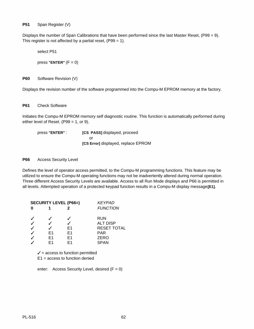
Defines the level of operator access permitted, to the Compu-M programming functions. This feature may beutilized to ensure the Compu-M operating functions may not be inadvertently altered during normal operation.Three different Access Security Levels are available. Access to all Run Mode displays and P66 is permitted inall levels. Attempted operation of a protected keypad function results in a Compu-M display message,[E1].
SECURITY LEVEL (P66=) KEYPAD0 1 2 FUNCTION
RUN ALT DISP E1 RESET TOTAL E1 E1 PAR E1 E1 ZERO E1 E1 SPAN
= access to function permittedE1 = access to function denied
enter: Access Security Level, desired (F = 0)
PL-516 62
P67 Direct Zero Entry
Allows direct access to the zero reference count.
Direct entry is intended for use when replacing software or hardware and it is not convenient to perform an initial zero at that time.
enter : 0 = disabled1 = enabled
press "ENTER"[Pc #####] displayed, previous count (display ’0’ if no previous count)press "12345" e.g. count value 12345press "ENTER"[oC 12345] e.g. new count value
P68 Direct Span Entry
Allows direct access to the span reference count.
Direct entry is intended for use when replacing software or hardware and it is not convenient to perform a span at that time to establish a proper initial span.
enter: 0 = disabled1 = enabledpress "ENTER"[Pc #####] displayed, previous count (display ’0’ if no previous count)press "67890" e.g. count value 67890press "ENTER"[SC 67890] e.g. new count value
P77 Initial Zero
Activates a Zero calibration which the Compu-M will utilize as a reference to which subsequent routine Zerocalibrations will be compared.
This parameter is generally utilized in response to a Display Message [E3] , when an accountable butmechanically non recoverable zero deviation, of greater than 12.5% of span, has occurred.
Refer to the appropriate recalibration section of this manual.
enter: "1" , Initial Zero (F = 0)
PL-516 63
P88 Initial Span
Activates a Span calibration which the Compu-M will utilize as a reference to which subsequent routine spancalibrations will be compared.
This parameter is generally utilized in response to a Display Message [E4] , when an accountable butmechanically non-recoverable zero calibration deviation, greater than 12.5% of span has occurred.
Refer to the appropriate recalibration section of this manual.
enter: "1" , Initial Span (F = 0)
P91 Calculator Input 1 (Belt Scale Applications Only)
Displays the count reference value of the summed inputs from load cell A and B when Compu-M board Bswitch SW1 is closed. Placing the test weight on load cell B side of the belt scale and entering the displayedvalue automatically advances the display to the next sequential parameter.
P92 Calculator Input 2 (Belt Scale Applications Only)
Displays the count reference value of the load cell B input when Compu-M board B switch SW1 is open.Without disturbing the test weight position (P-91), entering the value displayed automatically advances thedisplay to the next sequential parameter.
P93 Calculator Input 3 (Belt Scale Applications Only)
Displays the count reference value of the load cell B input when Compu-M board B switch SW1 is open.Placing the test weight on the load cell A side of the belt scale and entering the value displayed automaticallyadvances the display to the next sequential parameter.
P94 Calculator Input 4 (Belt Scale Applications Only)
Displays the count reference value of the summed inputs from load cell A and B when Compu-M board Bswitch SW1 is closed. Without disturbing the test weight position (P93), entering the value displayedautomatically advances the display to the next sequential parameter.
PL-516 64
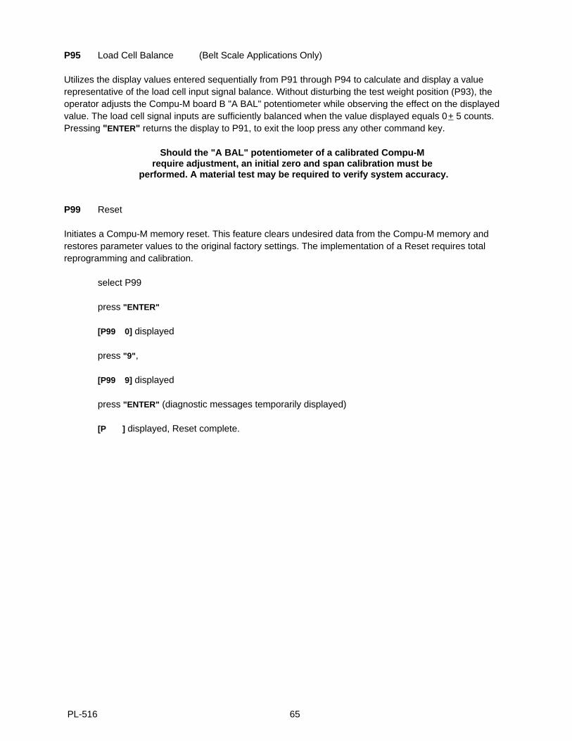
P95 Load Cell Balance (Belt Scale Applications Only)
Utilizes the display values entered sequentially from P91 through P94 to calculate and display a valuerepresentative of the load cell input signal balance. Without disturbing the test weight position (P93), theoperator adjusts the Compu-M board B "A BAL" potentiometer while observing the effect on the displayedvalue. The load cell signal inputs are sufficiently balanced when the value displayed equals 0 + 5 counts.Pressing "ENTER" returns the display to P91, to exit the loop press any other command key.
Should the "A BAL" potentiometer of a calibrated Compu-M require adjustment, an initial zero and span calibration must be
performed. A material test may be required to verify system accuracy.
P99 Reset
Initiates a Compu-M memory reset. This feature clears undesired data from the Compu-M memory andrestores parameter values to the original factory settings. The implementation of a Reset requires totalreprogramming and calibration.
select P99
press "ENTER"
[P99 0] displayed
press "9" ,
[P99 9] displayed
press "ENTER" (diagnostic messages temporarily displayed)
[P ] displayed, Reset complete.
PL-516 65

PL-516 66

MAINTENANCE
The Compu-M requires no maintenance.
The enclosure may be cleaned using a vacuum cleaner and a clean, dry paint brush.
It is also a good idea to check the associated load sensing device, according to its instruction manual.
PL-516 67

PL-516 68
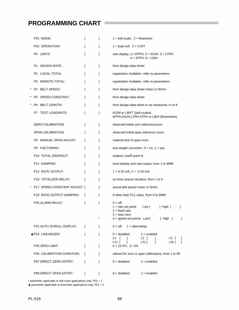
PROGRAMMING CHART
P01 MODE: [ ] 1 = belt scale, 2 = flowmeter
P02 OPERATION: [ ] 1 = load cell, 2 = LVDT
P0 UNITS: [ ] rate display, 1= MTPH, 2 = KG/H, 3 = LTPH, 4 = STPH, 5 = LB/H
P1 DESIGN RATE: [ ] from design data sheet
P2 LOCAL TOTAL: [ ] registration multiplier, refer to parameters
P3 REMOTE TOTAL: [ ] registration multiplier, refer to parameters
* P4 BELT SPEED: [ ] from design data sheet m/sec or ft/min.
* P5 SPEED CONSTANT: [ ] from design data sheet
* P6 BELT LENGTH: [ ] from design data sheet or as measured, m or ft
P7 TEST LOAD/RATE: [ ] KG/M or LB/FT (belt scales)MTPH,KG/H,LTPH,STPH or LB/H (flowmeters)
ZERO CALIBRATION [ ] observed Initial zero referencecount
SPAN CALIBRATION [ ] observed Initial span reference count
P8 MANUAL SPAN ADJUST: [ ] material test % span error
P9 FACTORING: [ ] test weight correction 0 = no, 1 = yes
P10 TOTAL DROPOUT: [ ] totalizer cutoff point %
P11 DAMPING: [ ] local display and rate output, from 1 to 9999
P12 RATE OUTPUT: [ ] 1 = 4-20 mA, 2 = 0-20 mA
P16 TOTALIZER RELAY: [ ] on-time closure duration, from 1 to 9
* P17 SPEED CONSTANT ADJUST: [ ] actual belt speed m/sec or ft/min
P18 RATE OUTPUT DAMPING: [ ] if other than P11 value, from 0 to 9999
P20 ALARM RELAY: [ ] 0 = off,1 = rate set point: Low [ ] High [ ]2 = fixed rate 3 = auto zero
* 4 = speed set points: Low [ ] High [ ]
P21 AUTO SCROLL DISPLAY: [ ] 0 = off, 1 = alternating
P24 LINEARIZER: [ ] 0 = disabled 1 = enabledL1 [ ] L2 [ ] L3 [ ]L1c [ ] L2c [ ] L3c [ ]
P25 ZERO LIMIT: [ ] 0 = 12.5%, 1= 2%
P30 CALIBRATION DURATION: [ ] utilized for zero or span calibrations, from 1 to 99
P67 DIRECT ZERO ENTRY: [ ] 0 = disabled 1 = enabled
P68 DIRECT SPAN ENTRY: [ ] 0 = disabled 1 = enabled
* parameter applicable to belt scale applications only, P01 = 1 parameter applicable to flowmeter applications only, P01 = 2
PL-516 69

PL-516 70


