Page 1
Eddy Currents October 2012
1
Create, Design, Engineer!
Computational Assessment of Eddy Currents in Rotating
Machines
1
Philippe [email protected]
The materials for this presentation were developed by the application teams of the Groupe Cedrat, at Cedrat SA and Magsoft Corporation.
The topologies used for the examples are drawn from real devices, they are only representative of the real devices.
Disclaimers
2
Page 2
Eddy Currents October 2012
2
Evaluation of eddy currents in:
• permanent magnets - radial field machines,
• airgap sleeves on rotor – radial field machines,
• coil conductors – axial field machines.
Why? Eddy currents may:
• alter the torque,
• affect the efficiency,
• generate heat.
Introduction
3
4 poles
12 slots
1 mm airgap
23 mm rotor radius
radial surface magnet
NDFE30
Br= 1.21
Mu= 1.0446
Rho= 1.6e-5 Ohm.m
Permanent Magnet - Radial
4
Page 3
Eddy Currents October 2012
3
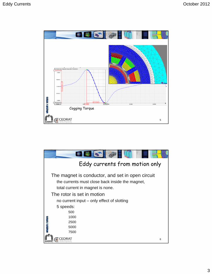
Cogging Torque
5
Eddy currents from motion only
The magnet is conductor, and set in open circuitthe currents must close back inside the magnet,
total current in magnet is none.
The rotor is set in motionno current input – only effect of slotting
5 speeds:500
1000
2500
5000
7500
6
Page 4
Eddy Currents October 2012
4
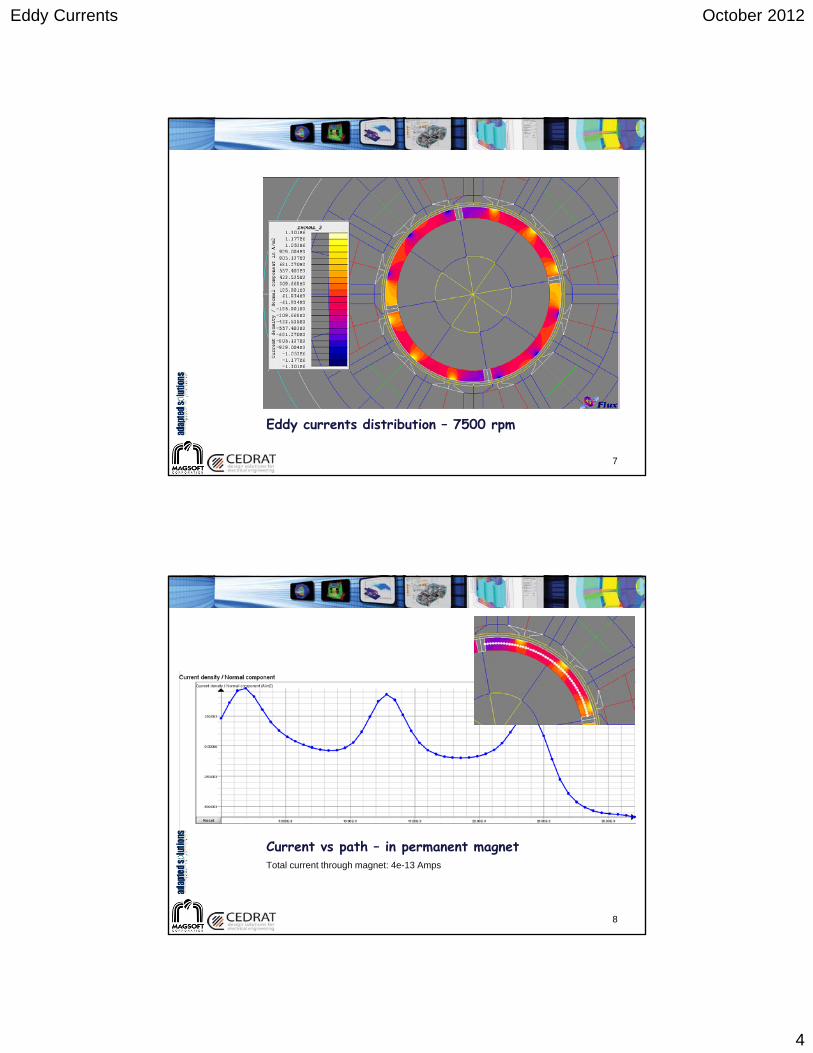
Eddy currents distribution – 7500 rpm
7
Current vs path – in permanent magnetTotal current through magnet: 4e-13 Amps
8
Page 5
Eddy Currents October 2012
5
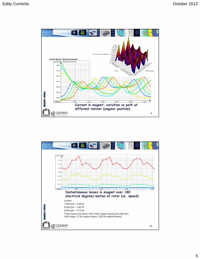
Current in magnet: variation vs path at different instant (angular position)
9
Instantaneous losses in magnet over 180 electrical degrees motion of rotor (vs. speed)
Losses:
7,500 rpm – 6.04 W
5,000 rpm – 2.82 W
2,500 rpm – 0.75 W
These losses are about 10% of the copper losses (at 5,000 rpm: 1kW output, 22 W copper losses, 2,82 W magnet losses)
10
Page 6
Eddy Currents October 2012
6
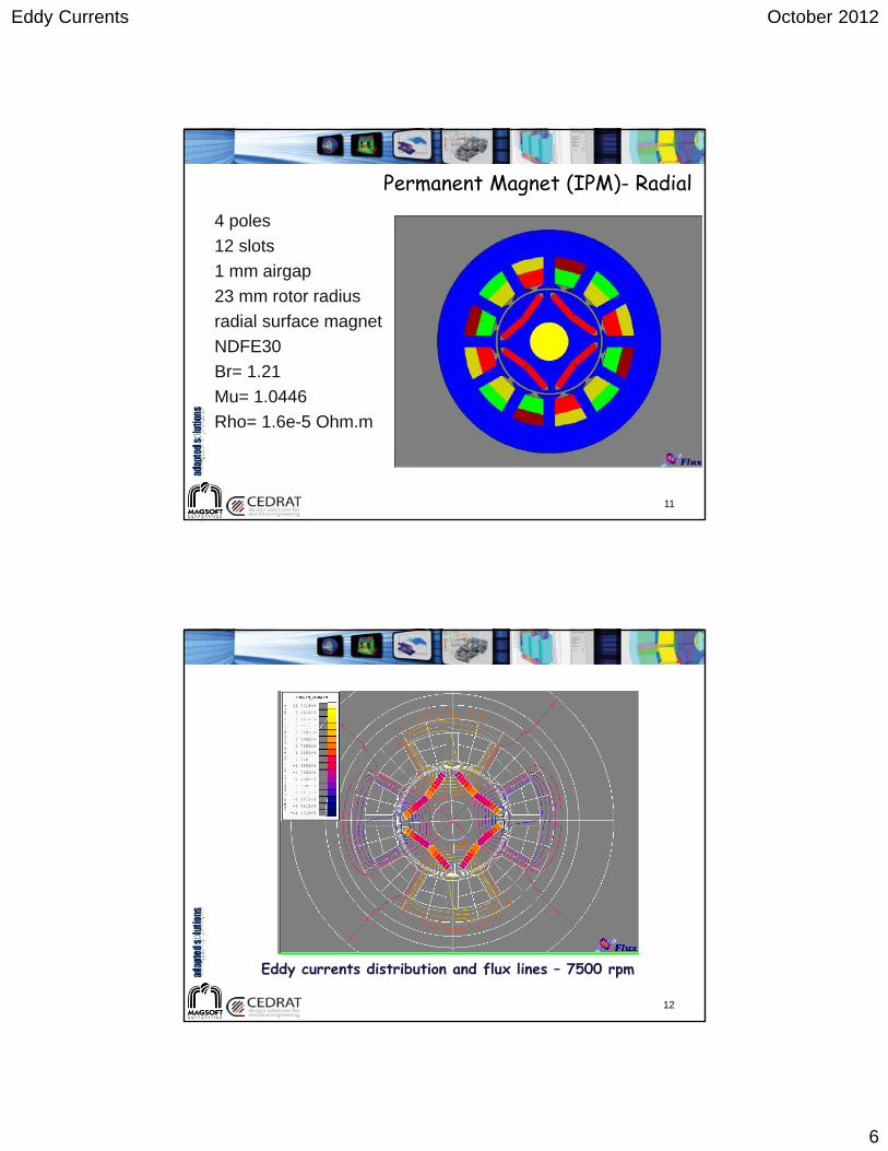
Permanent Magnet (IPM)- Radial
4 poles
12 slots
1 mm airgap
23 mm rotor radius
radial surface magnet
NDFE30
Br= 1.21
Mu= 1.0446
Rho= 1.6e-5 Ohm.m
11
Eddy currents distribution and flux lines – 7500 rpm
12
Page 7
Eddy Currents October 2012
7
Current vs path – in permanent magnetTotal current through magnet: 2e-13 Amps
13
500
0.0
Instantaneous losses in magnet over 180 electrical degrees motion of rotor (vs. speed)
Losses:
7,500 rpm – 0.15 W
5,000 rpm – 0.07 W
2,500 rpm – 0.02 W
These losses are less than .5 % of the copper losses,
14
Page 8
Eddy Currents October 2012
8
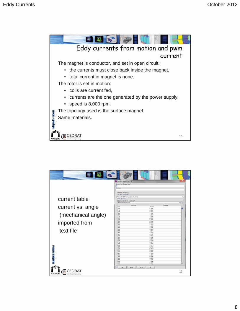
Eddy currents from motion and pwm current
The magnet is conductor, and set in open circuit:
• the currents must close back inside the magnet,
• total current in magnet is none.
The rotor is set in motion:
• coils are current fed,
• currents are the one generated by the power supply,
• speed is 8,000 rpm.
The topology used is the surface magnet.
Same materials.
15
current table
current vs. angle
(mechanical angle)
imported from
text file
16
Page 9
Eddy Currents October 2012
9
Input currents for three phases – 8,000 rpmNote the high content in harmonics
Irms = 10 Amps
17
Eddy currents distribution – 8,000 rpm
18
Page 10
Eddy Currents October 2012
10
Current vs path – in permanent magnetScale is in 1e6
Total current through magnet: 8e-7 Amps – still close to none.
19
Instantaneous losses in magnet over 360 electrical degrees motion of rotor
Losses:
Peak losses are 33 W for one magnet
Total losses: 49 W for the whole machine
20
Page 11
Eddy Currents October 2012
11
Airgap Sleeves on Rotor/Magnets
4 poles
12 slots
1.5 mm airgap
.75 mm can
Rho= 2.93e-8 Ohm.m
23 mm rotor radius
radial surface magnet
Ferrite
Br= 0.4
Mu= 1.0
21
Eddy currents from motion and multi harmonic current
The sleeve is conductor, and set in open circuitthe currents must close back inside the sleeve,
total current in the sleeve is none.
The rotor is set in motionspeed is 18,000 rpm
coils are current fed
fundamental, 5th and 7th harmonics are included
22
Page 12
Eddy Currents October 2012
12
Current description
23
Input currents for three phases – 18,000 rpmNote the content in harmonics
Irms = 10 Amps
24
Page 13
Eddy Currents October 2012
13
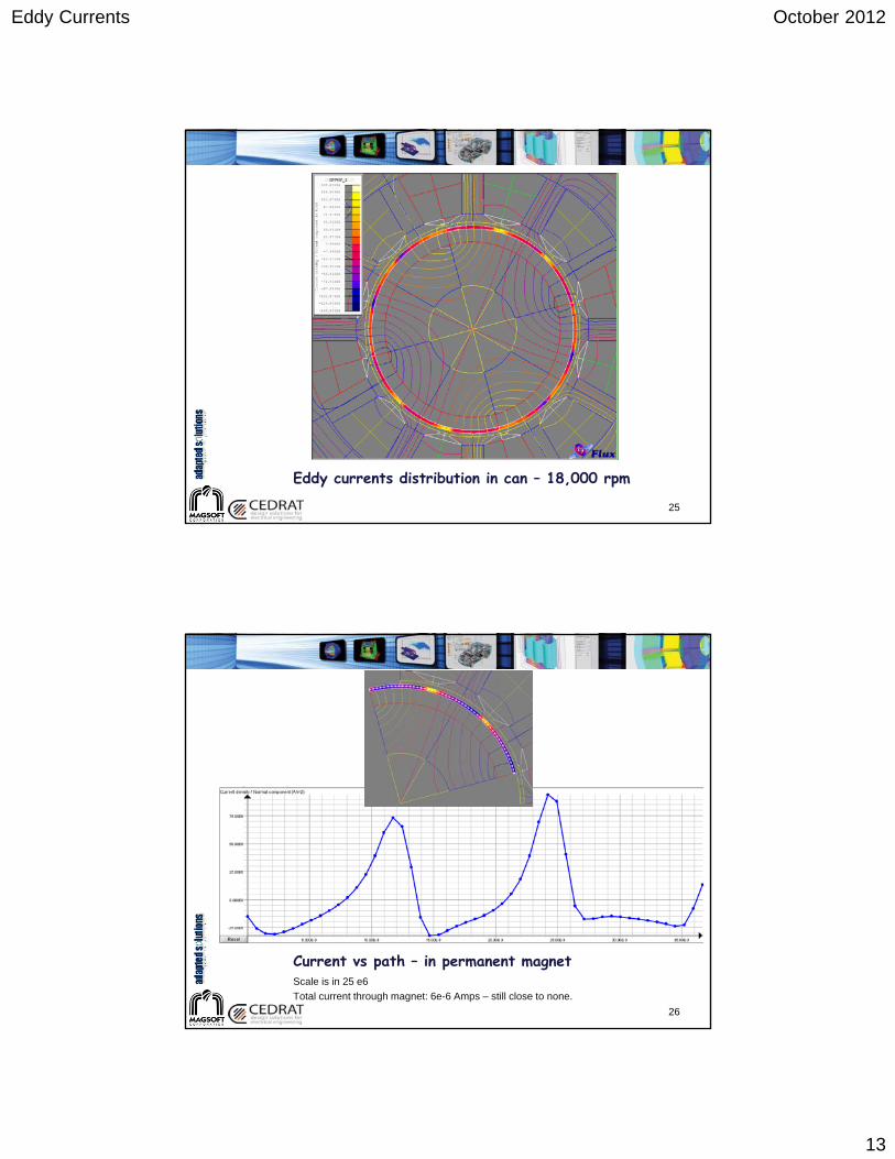
Eddy currents distribution in can – 18,000 rpm
25
Current vs path – in permanent magnetScale is in 25 e6
Total current through magnet: 6e-6 Amps – still close to none.
26
Page 14
Eddy Currents October 2012
14
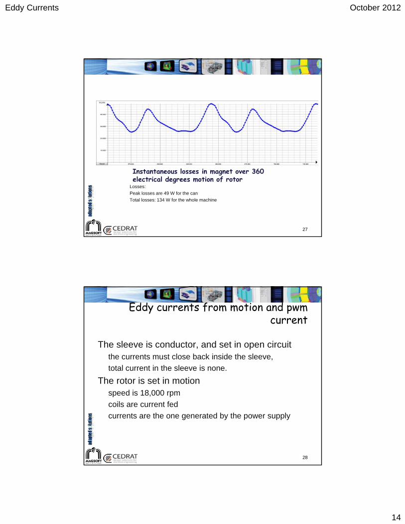
Instantaneous losses in magnet over 360 electrical degrees motion of rotor
Losses:
Peak losses are 49 W for the can
Total losses: 134 W for the whole machine
27
Eddy currents from motion and pwm current
The sleeve is conductor, and set in open circuitthe currents must close back inside the sleeve,
total current in the sleeve is none.
The rotor is set in motionspeed is 18,000 rpm
coils are current fed
currents are the one generated by the power supply
28
Page 15
Eddy Currents October 2012
15
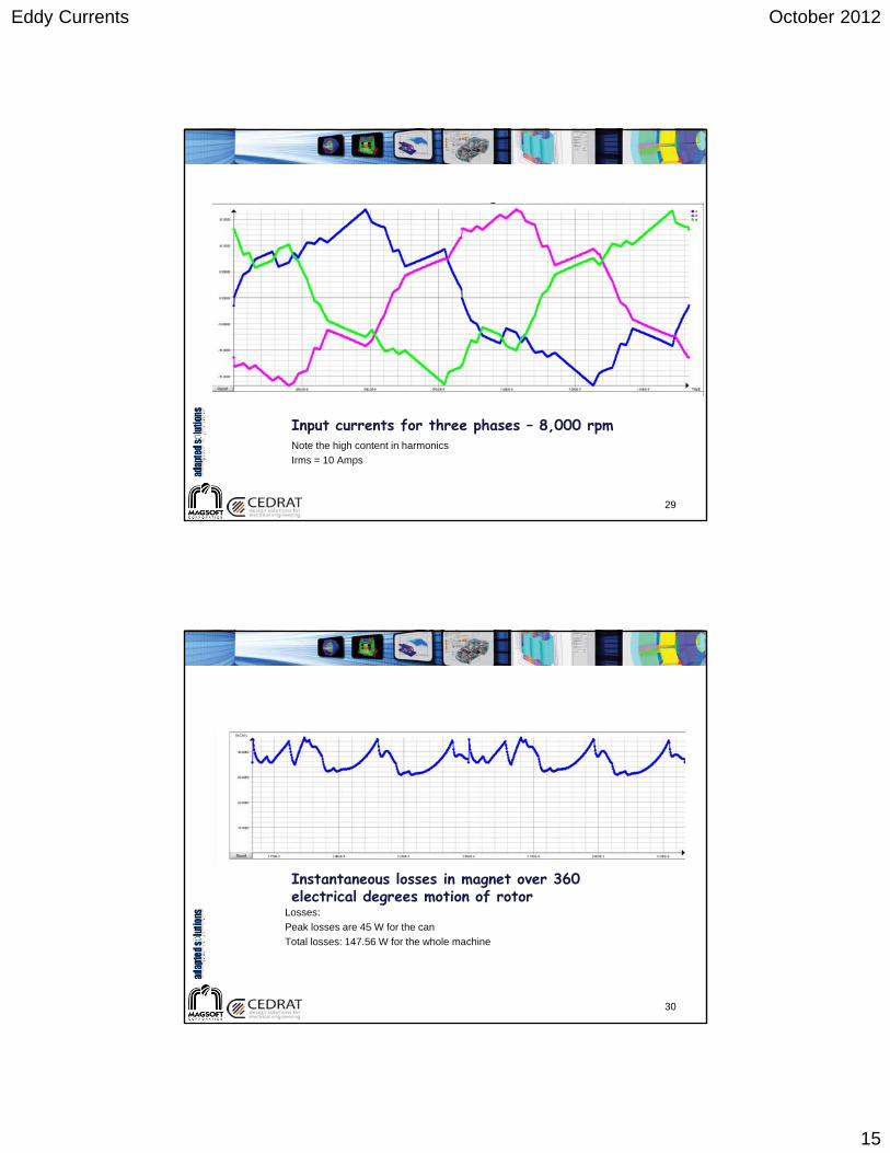
Input currents for three phases – 8,000 rpmNote the high content in harmonics
Irms = 10 Amps
29
Instantaneous losses in magnet over 360 electrical degrees motion of rotor
Losses:
Peak losses are 45 W for the can
Total losses: 147.56 W for the whole machine
30
Page 16
Eddy Currents October 2012
16
Computer Time
The losses is slightly higher than when trying to approximate the current with a formula containing the lower harmonics only (134 W)
721 time samples are needed to capture the harmonics when the current is described by a formula. 25 minutes on a i7 processor
1441 time samples are needed to capture the harmonics when the current is described by the tables 40 minutes on a i7 processor
31
What About 3D
32
Page 17
Eddy Currents October 2012
17
The same problem is being treated in 3D
The losses are confirmed at 125.08 W.
The lower number can be explained by the fact that in 2D we are underestimating the resistance in the 3rd
dimension
361 time samples were computed in 24 hours on a 64 bit i7 PC with 8GB of RAM
33
Minimization of losses in a PM machine
PM machine, 8 Poles – Coupler
High speed application
Inconel liner in airgap.
radius 146 mm, 2 mm thick
Other Machine
34
Page 18
Eddy Currents October 2012
18
Initial Model
35
Initial Model
Torque = -4069 N.m
Power = 2.55 MW
Losses (computed 1/8th device) = 319.38 kW
Losses (whole device) = 319.38 x 8 = 2.55 MW
36
Page 19
Eddy Currents October 2012
19
Modified Stack Distribution
37
Modified Stack Distribution
Torque = -92.37 N.m
Power = 58.27 kW
Losses (computed 1/8th device) = 7.32 kW
Losses (whole device) = 7.32 x 8 = 58.56 kW
38
Page 20
Eddy Currents October 2012
20
Laminated Inconel – Middle of Stack
39
Laminated Inconel – End stack
40
Page 21
Eddy Currents October 2012
21
Laminated Inconel – Losses vs Position
0
50
100
150
200
250
300
350
400
0 50 100 150 200 250 300 350 400 450 500
Watts/disc
Distance from center in mm
Losses
Losses
41
Laminated Inconel – Losses vs Position
42
Page 22
Eddy Currents October 2012
22
Spiral Sleeve - 1 rev
43
Spiral Sleeve - 2 rev
44
Page 23
Eddy Currents October 2012
23
Spiral Sleeve - 2 rev
45
Modified Stack Distribution
1 rev. sleeve
• Losses = 0.438 Watts
2 rev. sleeve
• Losses = 0.878 Watts
Page 24
Eddy Currents October 2012
24
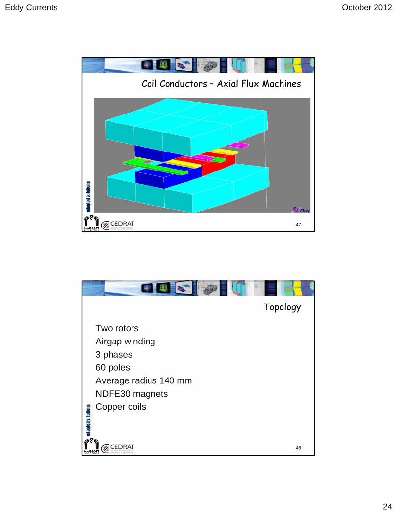
Coil Conductors – Axial Flux Machines
47
Topology
Two rotors
Airgap winding
3 phases
60 poles
Average radius 140 mm
NDFE30 magnets
Copper coils
48
Page 25
Eddy Currents October 2012
25
Detail Winding
49
Mesh47,000 nodes
145,000 1st order elements
50
Page 26
Eddy Currents October 2012
26
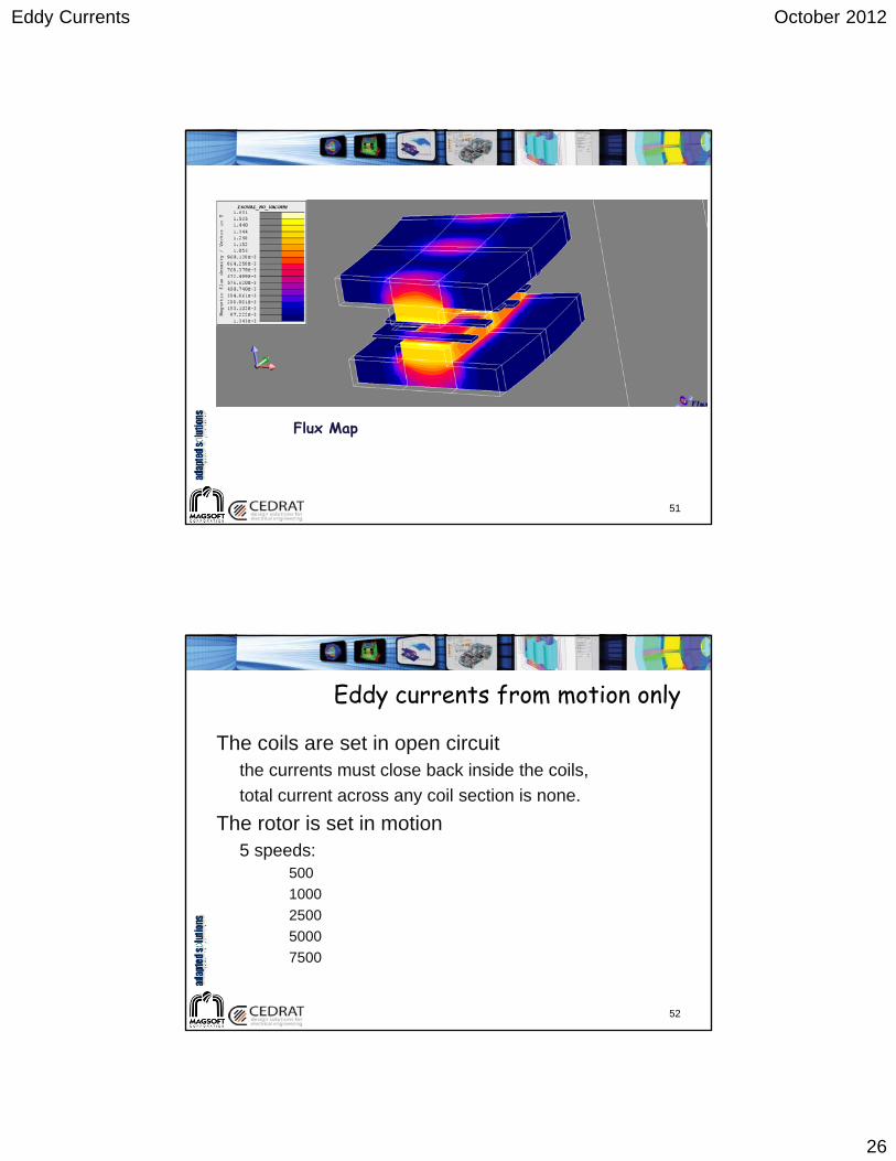
Flux Map
51
Eddy currents from motion only
The coils are set in open circuitthe currents must close back inside the coils,
total current across any coil section is none.
The rotor is set in motion5 speeds:
500
1000
2500
5000
7500
52
Page 27
Eddy Currents October 2012
27
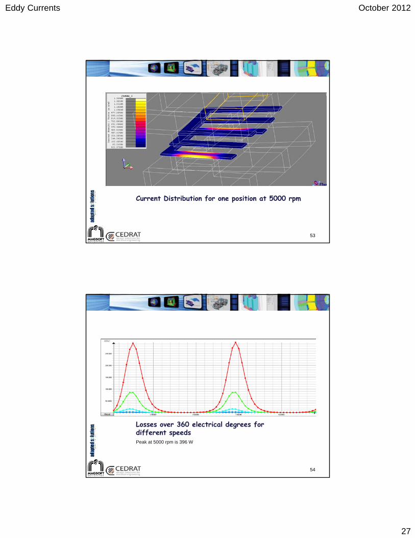
Current Distribution for one position at 5000 rpm
53
Losses over 360 electrical degrees for different speedsPeak at 5000 rpm is 396 W
54
Page 28
Eddy Currents October 2012
28
Detail of current flow in one coil at peak current
55
Instantaneous losses in the 3 phases over 2 poles (only two poles included) – 5,000 rpm
56
Losses:
Peak losses are 300 W for the coils
Total losses: 5,173 W for the whole machine
Total losses at 1,000 rpm: 237 W
65 time samples computed in 22 minutes.
Page 29
Eddy Currents October 2012
29
Conclusion
Eddy currents don’t have to remain a mystery
Computers are going faster
Codes are able to take advantage of multicore
Computation where performed on Flux Version 10.4
Flux connects to Matlab Simulink and Portunus
Flux is a component of Isight (SIMULIA)
GOT-It completes Flux with an integrated optimizer.
57