Nuclear and Radiological Engineering Computational Phantoms and Skeletal Dose Models for Adult and Paediatric Internal Dosimetry Wesley Bolch, PhD, PE, CHP Committee 2 of the ICRP and Chair, DOCAL Task Group Nuclear & Radiological Engineering, University of Florida Michael Wayson and Deanna Pafundi Nuclear & Radiological Engineering, University of Florida IAEA IDOS Symposium ‐ Session 3B Internal Dosimetry for Diagnostic and Therapeutic Nuclear Medicine Computational Phantoms & Imaging Based Patient‐Specific Models November 10, 2010
Transcript
Nuclear and Radiological Engineering
Computational Phantoms and Skeletal Dose Models for Adult and Paediatric Internal Dosimetry
Wesley Bolch, PhD, PE, CHPCommittee 2 of the ICRP and Chair, DOCAL Task GroupNuclear & Radiological Engineering, University of Florida
Michael Wayson and Deanna PafundiNuclear & Radiological Engineering, University of Florida
IAEA IDOS Symposium ‐
Session 3B
Internal Dosimetry for Diagnostic and Therapeutic Nuclear MedicineComputational Phantoms & Imaging Based Patient‐Specific Models
November 10, 2010
Nuclear and Radiological Engineering
The ICRP
C2 Task Groups – DOCAL and INDOSC3 Task Group – Radiopharmaceuticals
Nuclear and Radiological Engineering
NCRP Report 160 Trends in ionizing radiation exposure
Early 1980s 2006
~15% medical0.53 out of 3.6 mSv
~48% medical3.0 out of 6.2 mSv
Nuclear and Radiological Engineering
AAPM Press Release March 3, 2009
The NCRP report does not, however, "attempt to quantify the associated health risks nor specify the actions that should be taken in light of these
latest data," and AAPM experts are cautioning that these data do not necessarily indicate that the U.S. population is at any higher risk due to
this increased use of medical imaging. They caution that the new
report should not deter patients from getting medically‐appropriate imaging
exams. The NCRP findings on average population dose could be easily misinterpreted if applied to an individual patient’s medical situation.
Nuclear and Radiological Engineering
Impetus from NCRP Report 160 on Medical Dosimetry Retrospective
Dosimetry Studies
•
Radiation epidemiological studies
•
Quantifying past exposures and construction of dose‐response correlations
•
Emphasis on pediatric exposures
•
Examples ‐
NCI Radiation Epidemiological BranchStudy of pediatric CT imaging•
Retrieval of pediatric imaging records in the UK
•
Phase I –
Cohort study of 200,000 individuals (1985 to 2002)
•
Phase II – Nested case control study of 1000 individuals
•
Leukemia, brain, thyroid, breast cancers
Childhood Cancer Survivor Study (CCSS)
Nuclear and Radiological Engineering
Impetus from NCRP Report 160 on Medical Dosimetry Prospective
Dosimetry Studies
•
Assignment of organ doses under specific imaging protocols
•
Recording of individual doses in electronic medical records
•
Optimization of patient dose versus image quality
•
Example – Pediatric Nuclear Medicine ImagingSurvey of 13 major pediatric hospitals (JNM 2008; 49:1024–1027)
•
16 radiopharmaceutical examinations were surveyed
•
Minimum / maximum activity
•
Activity per unit body mass or body surface area
Conclusions•
Maximum variations –
factor of 8.5 in amount administered
•
Average variation –
factor of 3
Nuclear and Radiological Engineering
Computational Anatomic Phantoms Essential tool for organ dose assessment
•
Definition
‐
Computerized representation of human anatomy for use in radiation transport simulation of the medical imaging or radiation therapy
procedure
•
Need for phantoms vary with the medical application–
Nuclear Medicine•
3D patient images sometimes not available, especially for children
–
Diagnostic radiology and interventional fluoroscopy –
no 3D image
–
Computed tomography•
3D patient images available, problem –
organ segmentation
•
No anatomic information at edges of scan coverage
–
Radiotherapy•
Needed for characterizing out‐of‐field organ doses
Hybrid PhantomsSome selected and recently published hybrid phantoms
• XCAT Series ‐
Segars and Tsui (Proc IEEE, 2009)• RPI Series –
Zhang et al (PMB 2009) and Xu et al (PMB 2007)
• Virtual Family – Christ et al (PMB 2010)• FASH and MASH – Cassola et (PMB 2010)• UF Series ‐
Lee et al (PMB 2010)
XCAT Series FASH Virtual Family
Nuclear and Radiological Engineering
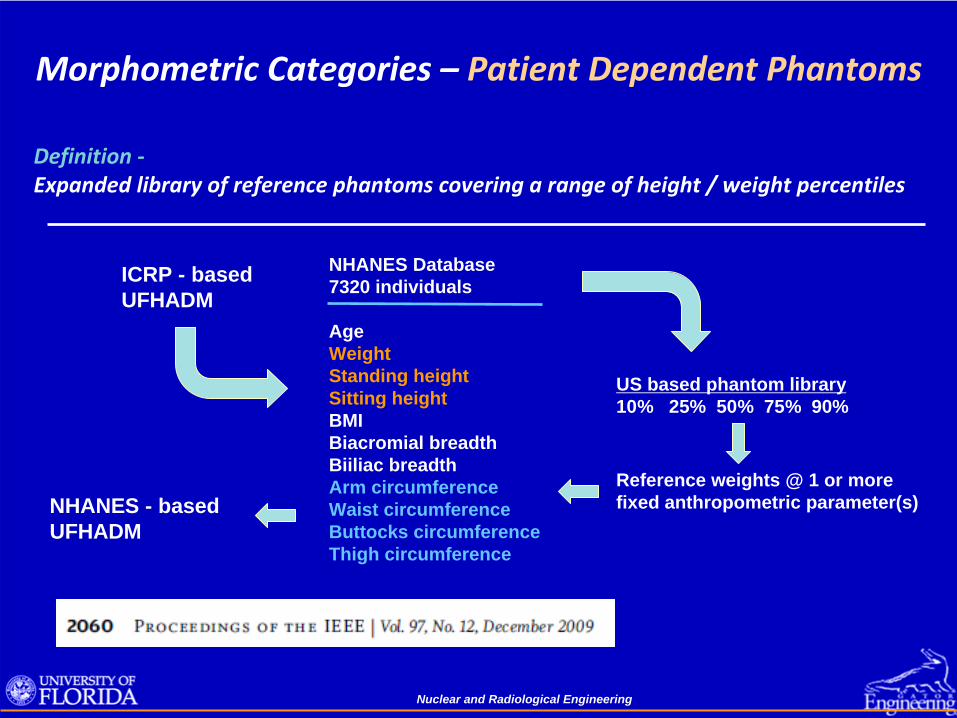
Morphometric Categories –
Reference PhantomsReference Individual ‐
An idealised male or female with characteristics
defined by the ICRP for the purpose of radiological protection, and with the anatomical and physiological characteristics defined in ICRP
Publication 89 (ICRP 2002).
Note –
While organ size / mass are specified in an ICRP reference phantom, organ shape, depth, position within the body are not defined by reference values
Nuclear and Radiological Engineering
Reference Phantoms Used by the ICRPEssentially all dose coefficients published to date by the ICRP are based on computational data generated using the ORNL stylized phantom series.
ORNL TM‐8381Cristy & Eckerman
One exception is ICRP Publication 74 on external dose coefficientsReference data taken from a variety of both stylized and voxel phantoms
Nuclear and Radiological Engineering
Reference Phantoms Adopted by the ICRPICRP Publication 110 – Adult Reference Computational Phantoms
Upcoming Publications from ICRP using the Publication 110 Phantoms• Reference dose conversion coefficients (DCC) for external radiations (revision of ICRP 74)• Reference DDC for space radiation environments• Reference DCC for aircrew exposures• Reference absorbed fractions (AF) for internal dose coefficients / nuclear medicine
Nuclear and Radiological Engineering
Reference Phantoms Adopted by the ICRPIn September 2008, ICRP established that its future reference phantoms forpediatric individuals would be based upon the UF series of hybrid phantoms
Nuclear and Radiological Engineering
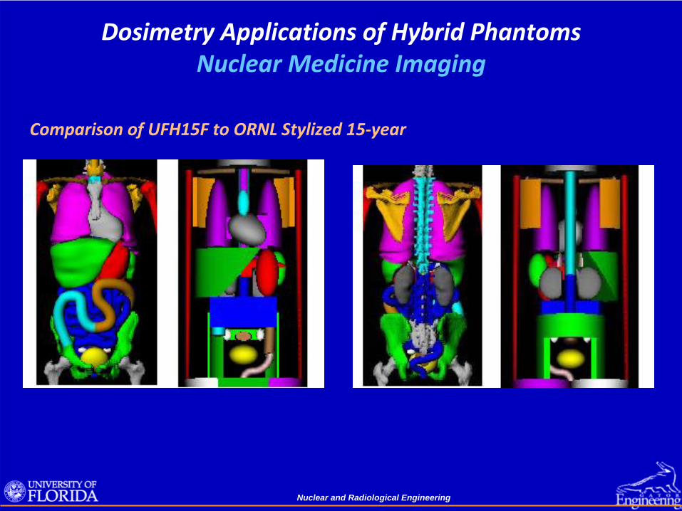
Dosimetry Applications of Hybrid Phantoms Nuclear Medicine Imaging
Comparison of UFH15F to ORNL Stylized 15‐year
Nuclear and Radiological Engineering
Dosimetry Applications of Hybrid Phantoms Nuclear Medicine Imaging
ICRP 89 Values 1170 2480 1100 4400 ICRP 89 Value 9350Ratio 1.00 1.00 1.05 0.99 Ratio 1.01
Total Skeletal Mass
Nuclear and Radiological Engineering
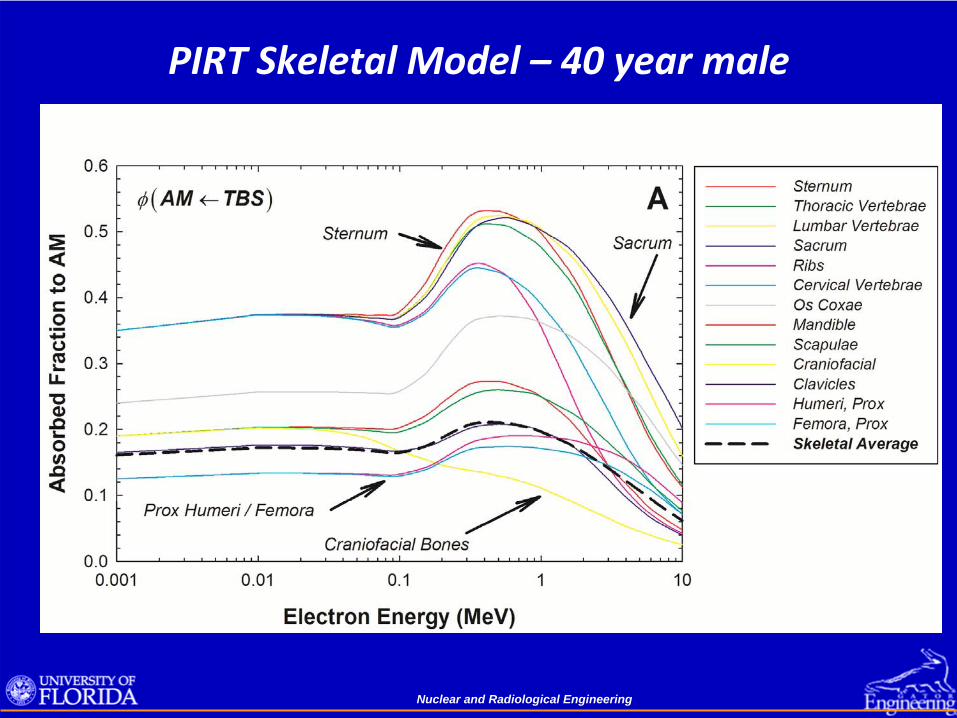
PIRT Skeletal Model – 40 year male
Nuclear and Radiological Engineering
PIRT Skeletal Model – 40 year male
Nuclear and Radiological Engineering
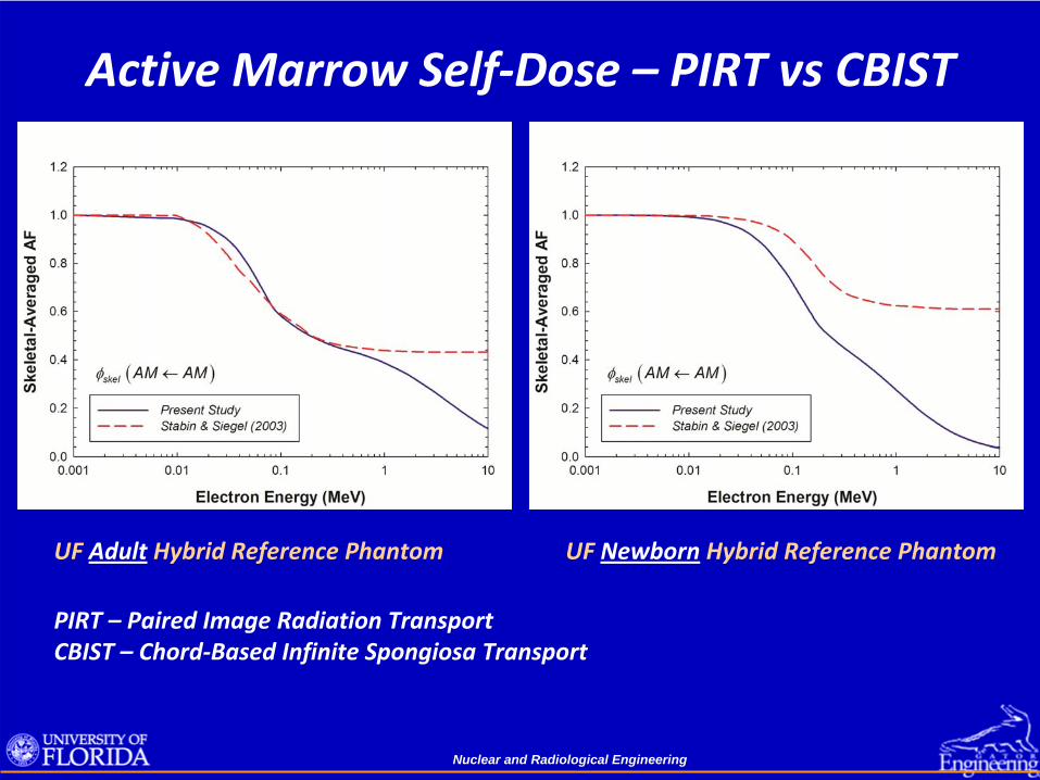
Active Marrow Self‐Dose – PIRT vs CBIST
UF Adult
Hybrid Reference Phantom UF Newborn
Hybrid Reference Phantom
PIRT – Paired Image Radiation TransportCBIST –
Chord‐Based Infinite Spongiosa Transport
Nuclear and Radiological Engineering
Photon Skeletal DosimetryTwo methods of photon skeletal dose in phantoms:
• Dose response functionsscore energy‐dependent photon fluence in spongiosa regionsconvolve the photon fluence with the fluence‐to‐dose DRF
• Three‐factor methodscore energy deposition in homogenous spongiosa regionsscale that energy deposition by three terms as belowDRBM ~ Dspongiosa when latter two factors approach unity
Nuclear and Radiological Engineering
Dose Enhancement Factors S(E) to AM and TM50
Target ‐
Active Marrow (AM) Target – Total Shallow Marrow (TM50
)
Dose enhancement due to photoelectrons created in the bone trabeculae thatthen exit and irradiate the adjacent marrow tissues
Nuclear and Radiological Engineering
Concluding Remarks• With the develop of hybrid phantom technology and the construction of
patient‐dependent phantom libraries, existing dosimetry software can be extended away from its historical reliance on reference phantoms.
• Phantom assignment can thus be made based upon patient height / weight and not only patient age.
• As image‐processing techniques become increasing automated, patient‐ sculpted phantoms and even patient‐specific phantoms with real‐time MC
assessment of organ dose can move from the research realm into daily clinical practice.
• Assessment of skeletal tissue dose is increasingly being refined
through micro‐ imaging and cadaver‐based reference models.
• Challenges for the future include adjustments of these models to include patient‐specific changes in skeletal size, marrow cellularity, and bone