Page 1
Computational simulation of the interaction between a thermal plume and ceiling jet Pedro Couto, Pedro J. Coelho
1/10
Computational simulation of the interaction between a thermal plume and ceiling jet
Pedro Couto, Pedro J. Coelho
Instituto Superior Técnico – Departamento de Engenharia Mecânica
Avenida Rovisco Pais, 1096-001 Lisboa, Portugal
[email protected]
Abstract
In confined spaces, as are the covered car parks, mostly of
the time it is required the installation of a mechanical
ventilation system.
Ventilation systems through jet fans improves the
efficient management of ventilation but the Portuguese
legislation are insufficient in that area. To fill this legal hole
the National Laboratory of Civil Engineering (LNEC) is
performing several experimental and computational studies
to establish rules for these type of systems.
The present work has focused on obtaining a
simplified numerical model which could reproduce the
LNEC experimental activity regarding the interaction
between a thermal plume and a ceiling jet. The main goals
are the reproduction of the velocity and temperature field
from experimental data. The validation of the results
obtained numerically were performed by comparison with
the experimental data.
Important aspects for numerical simulation such
cases like: turbulence model, treatment along the walls, type
of computational mesh and boundary conditions are
presented and discussed throughout this work.
Keywords: CFD, Wall jet, thermal plume, ventilation, car
park.
Introduction
Efficient ventilation and an effective smoke control
from a fire in a covered car park can be achieved through
the strategic placement of jet fans suspended near the
ceiling. However the Regulamento Técnico de Segurança
Contra Incêndio, Decrt 1532/2008 of 29 December [1] does
not cover the impulse ventilation systems. To address this
gap, exist a necessity of several studies that will enable the
formulation of a number of technical recommendations for
future regulation. This work follows on from an ongoing
doctoral thesis at the Instituto Superior Técnico in
partnership with the LNEC, and seeks to computational
model which simulate the interaction between a thermal
plume from a pool fire and a ceiling jet induced by two jet
fans parallel. The main goal is to evaluate the accuracy of
the computational results by comparison with experimental
data.
Jet fans Systems
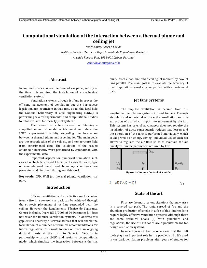
The impulse ventilation is derived from the
longitudinal ventilation systems in road tunnels. Through
air inlets and outlets takes place the insufflation and the
extraction of air, which is put into movement by the fan.
This system has several advantages: does not require the
installation of ducts consequently reduces load losses; and
the operation of the fans is performed individually which
could provide an energy saving; individual use of each fan
allows to regulate the air flow so as to maintain the air
quality within the parameters required by law.
Figure 1 – Volume Control of a jet fan.
(1)
State of the art
Fires are the most serious situations that may arise
in a covered car park. The rapid spread of fire and the
abundant production of smoke in a fire of this kind tends to
require highly effective ventilation systems. Although there
are some technical books [2] with guidelines and
regulations, the use of CFD codes are a popular means for
design ventilation systems.
In recent years it has become clear that the CFD
tools plays an important role in fire problems [3]. It’s used
in car park ventilation problems after years of studies for
Page 2
Computational simulation of the interaction between a thermal plume and ceiling jet Pedro Couto, Pedro J. Coelho
2/10
road tunnels with identical ventilating systems, [4] [5].
Chow [6] provides that a fire of a car (modelled by a 5 MW
of heat source) in a car park with the following dimensions
25 x 25 x 5 m3, causes an increase on the average
temperature. Temperature will exceed on 191 °C in a third
of the park area, revealing that the control smoke and
temperature from the ventilation system is essential to
allow the evacuation of people and the firefighting in
minimum safety conditions.
Various jet fans ventilation systems studies in car
parks have appearing [7] and the respective regulation also
[8]. In CFD Modelling Car Park Ventilation Systems [9], can
be found the information and parameters to study CFD
models for a car park ventilation system such as the
turbulence model, where the LES models and models of к-ε
family are proposed. However, in various studies [10] the
к-ε model reveals some limitations to simulate the lateral
dispersion of wall jets.
Viegas [11] using the FDS software, obtained
similar results to experimental data when simulate a car fire
(heat source of 4 MW) within a confined parking and
concludes that through the longitudinal fans it is obtained
dilution of the smoke stream in the ceiling jet allowing the
decrease of temperature along the same; and through a
thrust ventilation system with several lines of fans can
prevent the lateral spread of smoke.
Conservation equations for turbulent jet
The dynamic behaviour of a fluid is determined by
the laws of conservation:
Conservation of mass;
Conservation of momentum;
Conservation of energy.
The Reynolds transport theorem is used in the
conservation laws formulation. The theorem states that the
time variable of an extensive property of a system is the
sum of variation rate of the corresponding intensive
property inside the volume control plus the flow through
the intensive property of the control surface. Considering
the fluid is continuous, arbitrary control volume can
establish the equation for a given j variable as follows:
(2)
it is the flow along the control volume boundary and sj is
the source term.
The mass conservation equation or the continuity equation
can be written as:
(3)
Where 𝝆 is the density and U is the velocity. It is
valid for compressible and incompressible flows and
expresses the continuity of mass for a control volume.
The Newton's second law states that the change of
momentum is equal to the sum of the forces on the particles
of the fluid. The momentum equation can be described as:
(4)
Where pressure, the tensor of viscous stress
and f is the body forces.
Application of the Reynolds theorem to the first
law of thermodynamics give the equation of energy
conservation. It is written as [15]:
(5)
Where Et is the total energy q is the heat. The first
term of the second member corresponding to diffusive flow
and the remaining terms are heat release rate per unit
volume due to external working forces, forces densities and
surface forces, respectively.
Discretization
The computational simulation was done using the FLUENT
software. This software use the finite volume method to
convert the conservation equations of mass, momentum,
energy and remaining scalar in algebraic equations,
reaching to the numerical solution. This method consists in
the integration of the transport equations in each of the
control volumes, providing a discretized equation which
expresses the conservation law for each control volume.
The FLUENT solves the linear system of equations using the
Gauss-Seidel method together with a method of algebraic
multigrid. The finite volume formulation implies that any
resulting solution satisfies the integral conservation of
quantities such as mass, momentum and energy in any
volume control as well as in the entire field.
Page 3
Computational simulation of the interaction between a thermal plume and ceiling jet Pedro Couto, Pedro J. Coelho
3/10
Calculation Method
The FLUENT offers a choice of two solution algorithms:
segregated and coupled method.
The software manual recommends for incompressible flows
and low speeds the segregated method.
Within the segregated methods the FLUENT has several
options. The simulations present in this study used the
SIMPLE due to its robustness and stability in a wide range
of problems. The SIMPLE algorithm is essentially an
iterative procedure to predict and correct the calculation of
the pressure field, fulfilling the conservation of mass [12].
The solution of equations for the variables are addressed
sequentially and iteratively solution is obtained, to obtain
convergence of the solution [13].
Turbulence model
The turbulence model used in this work is
realizable к-ε model, RANS model. As the standard к-ε
model is based on the resolution of transport equations of
turbulent kinetic energy, к, and ε turbulent kinetic energy
dissipation rate. The main differences between the models
are: a new formulation for the turbulence viscosity
calculation; the modelling of the generation and destruction
terms in the transport equation for the turbulent kinetic
energy dissipation rate; and how to define the Prandtl
numbers that govern the turbulent diffusion terms of
turbulent kinetic energy and turbulent kinetic energy
dissipation rate.
The term "realizable" means that the model respect
certain mathematical constraints of the Reynolds stresses
consistent with the physics of turbulent flow [13]. The
realizable к-ε model get more precise jets dispersion rate
and provide best performances in flow with recirculation
and separation than the standard к-ε model.
As with other к-ε turbulence models, the realizable
model uses the hypothesis of Boussinesq to the definition of
Reynolds stresses. This hypothesis is based on an analogy
between turbulent and viscous stresses, assuming that the
turbulent stress are proportional to the average flow
velocity gradient. The advantage of this approach is the
reduction of computational effort to calculate the turbulent
viscosity, because rather than being necessary to introduce
six additional equations for each of the Reynolds tensor
components, simply enter an equation for the turbulent
viscosity. However the hypothesis of turbulent viscosity is
isotropic can be disadvantageous
Wall treatment
The turbulent flows are significantly affected by
the presence of walls. The average velocity field is affected
by the condition of non-slip that must be satisfied in the
wall. In the layers closest to the wall, the viscous effects
dampen the tangential components of speed, while the
kinetic effects of the flow in the vicinity dampen normal
fluctuations. Outside of the near-wall region the turbulence
is rapidly increased by the production of turbulent kinetic
energy due to high gradients at average speed.
The near wall modelling has a huge impact on the
validity of the numerical solutions because the walls are one
source of vorticity and turbulence, it is in near wall regions
that some variables have high gradients.
The wall laws are a very popular tool for flows with
high Reynolds number because save computer resources.
Experimental conditions
The experimental activities in LNEC were made in
a building with the following dimensions:
40 x 20 x 3 m3. The height was limited to 3 m and that is the
typical height for a car park in Portugal.
The experimental study was performed taking into
account a large number of situations but in this work the
focus will be on three of these studies: wall jet, ceiling jet
obtained through a heat source and the interaction between
a ceiling jet from two jet fans and a ceiling jet caused by a
heat source.
The fans used in the experimental work made
possible the operation of two pulse regimes, 15 N and 55 N,
the reversible unidirectional fans and blowers, 13 N and 51
N. However this work is restricted to study the
experimental results obtained for the unidirectional fans
which produce 55 N [15].
The heat source used in the experiment to simulate
a typical car fire was a cylindrical container with a diameter
equal to 0.72 m and height equal to 0.32 m. According with
Cruz [15], the heat output released under these conditions
is close to 750 kW corresponding to 1/8 of a typical car fire
[23]. The combustible was gasoline.
The heat release from the heat source is obtained
through the expression 6 [15].
)A (6)
Page 4
Computational simulation of the interaction between a thermal plume and ceiling jet Pedro Couto, Pedro J. Coelho
4/10
Wall jet - study
Wall jet – fundamentals
A schematic representation of a parietal jet is shown in
Figure 2.
Figure 2 – Schematic representation of a wall jet (adapted from
[3]).
It is possible differentiate three regions in the wall jet flow
[15]:
Region - does not exists influence from
wall on the flow, is the axial distance from the jet
and is the distance between the centre of the jet
and the wall;
Region – the wall interference cause
a diversion on the flow toward to the wall;
Region – the flow has parietal jet flow
characteristics and the influence of the wall is
more significant.
The dimensionless axial velocity profile of the jet axis is
given by the expression 7. For wall jets the constant K take a
value between 8,5 and 9 [16].
(
(7)
For confined radial jets, Wood [17] established an empirical
relationship for lateral and vertical dispersion:
(
(8)
Experimental data
The jet fan was on an elevated structure (2.5 m above the
ground) and the anemometers were on different levels,
between 0.20 m and 2.95 m from the ground. The mesh
measurement was implemented in an area of 10 x 28 m as
shown in Figure 3. Data was acquired during 6 minutes with
a frequency of 2 Hz.
The ventilator speed was 22 m / s.
CFD model – characteristics
Domain dimensions - The dimensions of domain were
60 x 7 x 3 m3, figure 4. The ventilator was modelled by a
cylinder: 0,38 m of diameter and 2,5 m of length.
Figure 3 - Schematic representation of practical work - wall jet.
Figure 4 - Schematic representation of the domain - wall jet.
Computational Mesh - The computational mesh was
generated with hexahedral elements, which produce more
accurate results for the cell centered gradients calculation
and the skewness is smaller. For better results the mesh
was aligned with the flow.
On the ceiling was chosen a better refinement to solve the
boundary layer.
The generated mesh has 1256348 cells.
Page 5
Computational simulation of the interaction between a thermal plume and ceiling jet Pedro Couto, Pedro J. Coelho
5/10
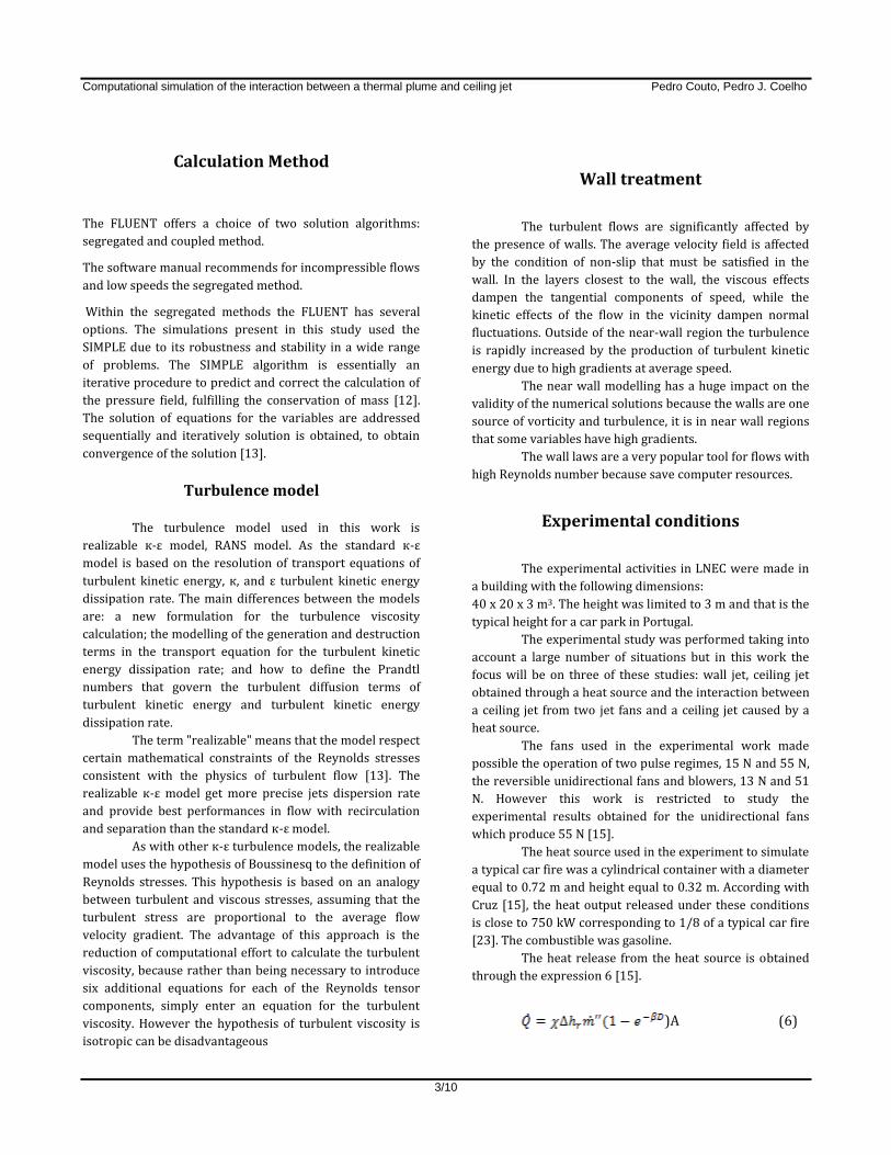
Boundary conditions – On the walls, floor and ceiling, it
was imposed a non-slip condition and was allowed the heat
exchange by convection. h∞ is the convection coefficient, T∞
is the outside temperature, is the thickness and is the
specific heat.
Table 1 – Boundary conditions for walls - wall jet.
For lateral boundary the model established a pressure
outlet boundary.
Table 2 – Boundary conditions for lateral face - wall jet.
The boundary condition imposed on the fan was an inlet
velocity of 22 m / s with horizontal direction.
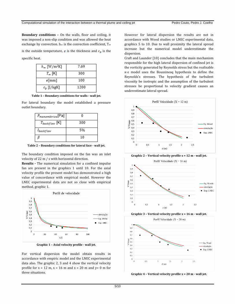
Results - The numerical simulation for a confined impulse
fan are present in the graphics 1 until 10. For the axial
velocity profile the present model has demonstrated a high
value of concordance with empirical model. However the
LNEC experimental data are not so close with empirical
method, graphic 1.
Graphic 1 – Axial velocity profile - wall jet.
For vertical dispersion the model obtain results in
accordance with empiric model and the LNEC experimental
data also. The graphic 2, 3 and 4 show the vertical velocity
profile for x = 12 m, x = 16 m and x = 20 m and y= 0 m for
three situations.
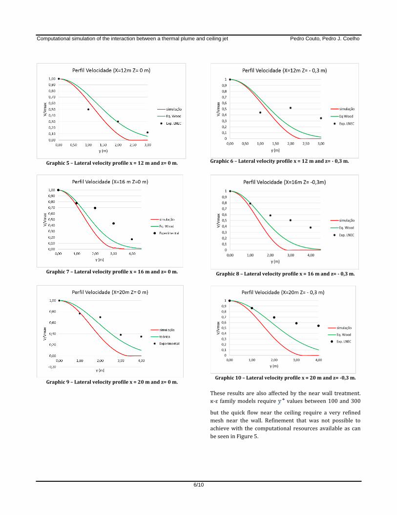
However for lateral dispersion the results are not in
accordance with Wood studies or LNEC experimental data,
graphics 5 to 10. Due to wall proximity the lateral spread
increase but the numerical model underestimate the
dispersion.
Craft and Launder [10] concludes that the main mechanism
responsible for the high lateral dispersion of confined jet is
the vorticity generated by Reynolds stress but the realizable
к-ε model uses the Boussinesq hypothesis to define the
Reynolds’s stresses. The hypothesis of the turbulent
viscosity be isotropic and the assumption of the turbulent
stresses be proportional to velocity gradient causes an
underestimate lateral spread.
Graphic 2 – Vertical velocity profile x = 12 m - wall jet.
Graphic 3 – Vertical velocity profile x = 16 m - wall jet.
Graphic 4 – Vertical velocity profile x = 20 m - wall jet.
Page 6
Computational simulation of the interaction between a thermal plume and ceiling jet Pedro Couto, Pedro J. Coelho
6/10
Graphic 5 – Lateral velocity profile x = 12 m and z= 0 m.
Graphic 7 – Lateral velocity profile x = 16 m and z= 0 m.
Graphic 9 – Lateral velocity profile x = 20 m and z= 0 m.
Graphic 6 – Lateral velocity profile x = 12 m and z= - 0,3 m.
Graphic 8 – Lateral velocity profile x = 16 m and z= - 0,3 m.
Graphic 10 – Lateral velocity profile x = 20 m and z= -0,3 m.
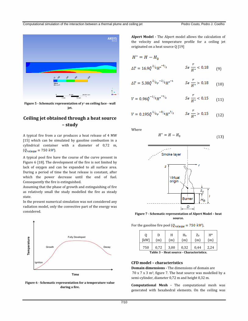
These results are also affected by the near wall treatment.
к-ε family models require values between 100 and 300
but the quick flow near the ceiling require a very refined
mesh near the wall. Refinement that was not possible to
achieve with the computational resources available as can
be seen in Figure 5.
Page 7
Computational simulation of the interaction between a thermal plume and ceiling jet Pedro Couto, Pedro J. Coelho
7/10
Figure 5 - Schematic representation of y+ on ceiling face - wall
jet.
Ceiling jet obtained through a heat source
– study
A typical fire from a car produces a heat release of 4 MW
[15] which can be simulated by gasoline combustion in a
cylindrical container with a diameter of 0,72 m,
( ).
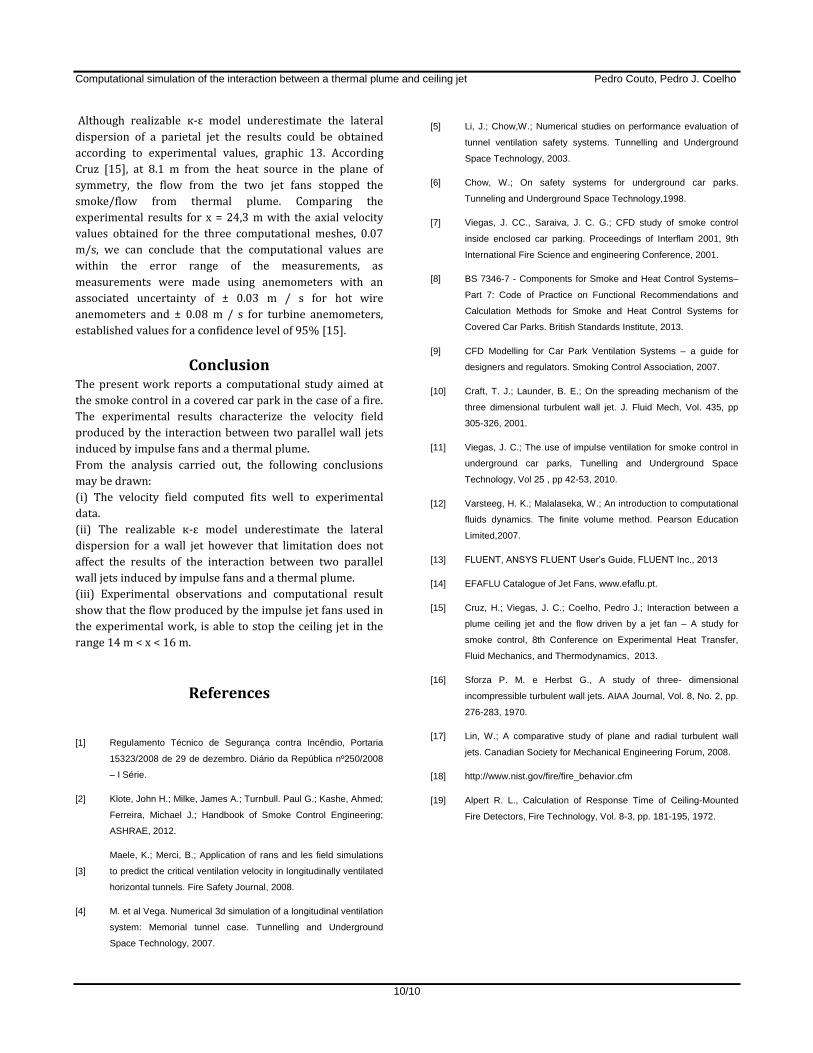
A typical pool fire have the course of the curve present in
Figure 6 [18]. The development of the fire is not limited by
lack of oxygen and can be expanded to all surface area.
During a period of time the heat release is constant, after
which the power decrease until the end of fuel.
Consequently the fire is extinguished.
Assuming that the phase of growth and extinguishing of fire
as relatively small the study modelled the fire as steady
state.
In the present numerical simulation was not considered any
radiation model, only the convective part of the energy was
considered.
Figure 6 - Schematic representation for a temperature value
during a fire.
Alpert Model - The Alpert model allows the calculation of
the velocity and temperature profile for a ceiling jet
originated on a heat source Q [19]
(9)
(10)
(11)
(12)
Where
(13)
Figure 7 - Schematic representation of Alpert Model – heat
source.
For the gasoline fire pool ( ),
Q
[kW]
D
(m)
H
(m)
Hb
(m)
Z0
(m)
H*
(m)
750 0,72 3,00 0,32 0,44 2,24
Table 3 – Heat source - Characteristics.
CFD model – characteristics
Domain dimensions - The dimensions of domain are
70 x 7 x 3 m3, figure 7. The heat source was modelled by a
semi-cylinder, diameter 0,72 m and height 0,32 m.
Computational Mesh - The computational mesh was
generated with hexahedral elements. On the ceiling was
Page 8
Computational simulation of the interaction between a thermal plume and ceiling jet Pedro Couto, Pedro J. Coelho
8/10
chosen a refinement to solve the boundary layer and was
applied the face sizing tool of Ansys Design Modeler to
increase the refinement on the top face of the semi-cylinder.
The generated mesh has 1555071 cells.
Boundary conditions – On the walls, floor, lateral and
ceiling boundary, and the conditions are equal as the wall
jet study, table 1 and 2. A symmetric plane was used as
shown in Figure 7 to reduce the computational effort.
Figure 7 - Schematic representation for boundary conditions.
Results - From the graphic 11 concludes that numerical
results has high correlation with Alpert model and
experimental data for velocity field.
The computational results for temperature present in
graphic 12, shows that the temperature distribution near
the source heat, , where r is the axial distance
from the pool fire center, presents some discrepancy with
Alpert model. The maximum difference obtain was 50º C for
, in this region the temperature gradient is high
and the model has more difficulties.
Graphic 11 – Temperature profile (dimensionless).
Graphic 12 – Velocity profile (dimensionless).
Interaction between a ceiling jet from two
jet fans and a ceiling jet originated by a
heat source – study The modelling of a fire phenomenon associated with the
flow of the ventilation system is complex and involves
several options and simplifications. In the previous points
was used models widely validated in comparison with
computational results and proceeded an analysis of the
choices made. The numerical results were compared to
models established in the literature as well as the results
obtained experimentally in the activities carried out by
LNEC. In these previous studies it was concluded that the
proposed models obtained a satisfactory results, except for
the lateral dispersion of a wall jet.
In this chapter, using the same simplifications and choices
previously made will be described the computational model
for the interaction between a ceiling jet from two jet fans
and a ceiling jet originated by a heat source.
Due to the specific model under study it is only possible
validate the results obtained numerically with experimental
data from LNEC works.
Taking account the experimental data available, the goal of
present study was to find the distance at a ceiling jet from
two jet fans can stop the smoke/thermal plume originated
in a pool fire. Cruz [15] conclude that the smoke from a heat
source ( ) is stopped at 14,3 m of distance
of two ventilators (Vout = 22 m / s) [15], figure 8.
Page 9
Computational simulation of the interaction between a thermal plume and ceiling jet Pedro Couto, Pedro J. Coelho
9/10
Figure 8 - Schematic representation of practical work -
Interaction between a ceiling jet from two jet fans and a ceiling
jet originated by a heat source .
In this case was performed a mesh independency study to
check the influence of mesh discretization.
CFD model – characteristics
Domain dimensions - The dimensions of domain are
70 x 7 x 3 m3, figure 8. The heat source was modelled by a
semi-cylinder, 0,72 m of diameter and 0,32 m of height. The
ventilator was modelled by a cylinder, diameter equal to
0,38 m and length equal to 2.5 m.
Figure 9 – Domain Dimensions.
Computational Mesh – in this study was generated three
mesh with similar characteristics of previous meshes.
Table 4 – Number of Cells in each mesh.
Boundary conditions – On the walls, floor, lateral and
ceiling boundary the conditions are equal as the wall jet
study. A symmetry plane was used as shown in Figure 9 to
reduce the computational effort.
Results - The flow from two wall jet fans and their
interaction with a thermal plume is not supported by any
theoretical or empirical model like the previous cases. The
validation of results to velocity field of the interaction was
based on comparison with experimental results obtained at
LNEC. The experimental results shows that the flow from
ventilators stop the ceiling jet at x = 24,3 m from the
ventilators (8,1 m from heat source) in the symmetric plane.
Figure 10 - Schematic representation of velocity profile in
symmetric plane - Interaction between a ceiling jet from two
jet fans and a ceiling jet originated by a heat source.
Graphic 13 – Velocity profile in symmetric plane - Interaction
between a ceiling jet from two jet fans and a ceiling jet
originated by a heat source.
Page 10
Computational simulation of the interaction between a thermal plume and ceiling jet Pedro Couto, Pedro J. Coelho
10/10
Although realizable к-ε model underestimate the lateral
dispersion of a parietal jet the results could be obtained
according to experimental values, graphic 13. According
Cruz [15], at 8.1 m from the heat source in the plane of
symmetry, the flow from the two jet fans stopped the
smoke/flow from thermal plume. Comparing the
experimental results for x = 24,3 m with the axial velocity
values obtained for the three computational meshes, 0.07
m/s, we can conclude that the computational values are
within the error range of the measurements, as
measurements were made using anemometers with an
associated uncertainty of ± 0.03 m / s for hot wire
anemometers and ± 0.08 m / s for turbine anemometers,
established values for a confidence level of 95% [15].
Conclusion The present work reports a computational study aimed at
the smoke control in a covered car park in the case of a fire.
The experimental results characterize the velocity field
produced by the interaction between two parallel wall jets
induced by impulse fans and a thermal plume.
From the analysis carried out, the following conclusions
may be drawn:
(i) The velocity field computed fits well to experimental
data.
(ii) The realizable к-ε model underestimate the lateral
dispersion for a wall jet however that limitation does not
affect the results of the interaction between two parallel
wall jets induced by impulse fans and a thermal plume.
(iii) Experimental observations and computational result
show that the flow produced by the impulse jet fans used in
the experimental work, is able to stop the ceiling jet in the
range 14 m < x < 16 m.
References
[1] Regulamento Técnico de Segurança contra Incêndio, Portaria
15323/2008 de 29 de dezembro. Diário da República nº250/2008
– I Série.
[2] Klote, John H.; Milke, James A.; Turnbull. Paul G.; Kashe, Ahmed;
Ferreira, Michael J.; Handbook of Smoke Control Engineering;
ASHRAE, 2012.
[3]
Maele, K.; Merci, B.; Application of rans and les field simulations
to predict the critical ventilation velocity in longitudinally ventilated
horizontal tunnels. Fire Safety Journal, 2008.
[4] M. et al Vega. Numerical 3d simulation of a longitudinal ventilation
system: Memorial tunnel case. Tunnelling and Underground
Space Technology, 2007.
[5] Li, J.; Chow,W.; Numerical studies on performance evaluation of
tunnel ventilation safety systems. Tunnelling and Underground
Space Technology, 2003.
[6] Chow, W.; On safety systems for underground car parks.
Tunneling and Underground Space Technology,1998.
[7] Viegas, J. CC., Saraiva, J. C. G.; CFD study of smoke control
inside enclosed car parking. Proceedings of Interflam 2001, 9th
International Fire Science and engineering Conference, 2001.
[8] BS 7346-7 - Components for Smoke and Heat Control Systems–
Part 7: Code of Practice on Functional Recommendations and
Calculation Methods for Smoke and Heat Control Systems for
Covered Car Parks. British Standards Institute, 2013.
[9] CFD Modelling for Car Park Ventilation Systems – a guide for
designers and regulators. Smoking Control Association, 2007.
[10] Craft, T. J.; Launder, B. E.; On the spreading mechanism of the
three dimensional turbulent wall jet. J. Fluid Mech, Vol. 435, pp
305-326, 2001.
[11] Viegas, J. C.; The use of impulse ventilation for smoke control in
underground car parks, Tunelling and Underground Space
Technology, Vol 25 , pp 42-53, 2010.
[12] Varsteeg, H. K.; Malalaseka, W.; An introduction to computational
fluids dynamics. The finite volume method. Pearson Education
Limited,2007.
[13] FLUENT, ANSYS FLUENT User’s Guide, FLUENT Inc., 2013
[14] EFAFLU Catalogue of Jet Fans, www.efaflu.pt.
[15] Cruz, H.; Viegas, J. C.; Coelho, Pedro J.; Interaction between a
plume ceiling jet and the flow driven by a jet fan – A study for
smoke control, 8th Conference on Experimental Heat Transfer,
Fluid Mechanics, and Thermodynamics, 2013.
[16] Sforza P. M. e Herbst G., A study of three- dimensional
incompressible turbulent wall jets. AIAA Journal, Vol. 8, No. 2, pp.
276-283, 1970.
[17] Lin, W.; A comparative study of plane and radial turbulent wall
jets. Canadian Society for Mechanical Engineering Forum, 2008.
[18] http://www.nist.gov/fire/fire_behavior.cfm
[19] Alpert R. L., Calculation of Response Time of Ceiling-Mounted
Fire Detectors, Fire Technology, Vol. 8-3, pp. 181-195, 1972.